JP2011002012A - Pipe joint structure - Google Patents

Pipe joint structure Download PDF

Info

Publication number
JP2011002012A
JP2011002012A JP2009145024A JP2009145024A JP2011002012A JP 2011002012 A JP2011002012 A JP 2011002012A JP 2009145024 A JP2009145024 A JP 2009145024A JP 2009145024 A JP2009145024 A JP 2009145024A JP 2011002012 A JP2011002012 A JP 2011002012A
Authority
JP
Japan
Prior art keywords
resin pipe
resin
joint
pipe member
inner layer
Prior art date
Legal status (The legal status is an assumption and is not a legal conclusion. Google has not performed a legal analysis and makes no representation as to the accuracy of the status listed.)
Pending
Application number
JP2009145024A
Other languages
Japanese (ja)
Inventor
Hiroyasu Hiratsuka
裕康 平塚
Toyomasa Matsumura
豊正 松村
Motomune Sasaki
基宗 佐々木
Current Assignee (The listed assignees may be inaccurate. Google has not performed a legal analysis and makes no representation or warranty as to the accuracy of the list.)
Sekisui Chemical Co Ltd
Original Assignee
Sekisui Chemical Co Ltd
Priority date (The priority date is an assumption and is not a legal conclusion. Google has not performed a legal analysis and makes no representation as to the accuracy of the date listed.)
Filing date
Publication date
Application filed by Sekisui Chemical Co Ltd filed Critical Sekisui Chemical Co Ltd
Priority to JP2009145024A priority Critical patent/JP2011002012A/en
Publication of JP2011002012A publication Critical patent/JP2011002012A/en
Pending legal-status Critical Current

Links

Images

Landscapes

  • Joints Allowing Movement (AREA)
  • Non-Disconnectible Joints And Screw-Threaded Joints (AREA)

Abstract

【課題】主に、樹脂製管継手の熱伸縮による耐疲労破壊強度の向上を図り得るようにする。
【解決手段】短管状の継手本体2と、継手本体2の端部に設けられた複数の接着受口部3とを有すると共に、接着受口部3が、樹脂製管部材4の端部を挿入接着固定可能に構成された管継手部構造であって、接着受口部3は、その内層12に、樹脂製管部材4と接着接合可能な樹脂材料14を有する複合受口部11とされ、複合受口部11の外層13と、継手本体2とは、樹脂製管部材4の熱伸縮応力を吸収可能な樹脂材料18で構成されるようにしている。
【選択図】図1
An object of the present invention is to make it possible to improve fatigue fracture resistance mainly by thermal expansion and contraction of a resin pipe joint.
A short tubular joint body 2 and a plurality of adhesive receiving portions 3 provided at the end of the joint main body 2, and the adhesive receiving portion 3 at the end of the resin pipe member 4 are provided. It is a pipe joint part structure configured to be capable of being inserted and fixed, and the adhesive receiving part 3 is a composite receiving part 11 having a resin material 14 that can be adhesively bonded to the resin pipe member 4 on its inner layer 12. The outer layer 13 of the composite receiving part 11 and the joint body 2 are made of a resin material 18 that can absorb the thermal expansion and contraction stress of the resin pipe member 4.
[Selection] Figure 1

Description

この発明は、管継手部構造に関するものである。   The present invention relates to a pipe joint part structure.

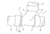
樹脂配管の接続などには、例えば、図6に示すような樹脂製管継手1が、一般的に用いられている。このような樹脂製管継手1は、ほぼ短管状の継手本体2と、この継手本体2の端部に設けられた接着受口部3(または受口部3)とを有している。そして、樹脂製管継手1の接着受口部3に対して、樹脂製管部材4(図7参照)の端部を挿入接着固定することにより、樹脂製管部材4の接続を容易に行い得るよう構成している。このような樹脂製管継手1には、例えば、図示のようなLT型のもの(接着受口部3を3箇所有するもの)や、特に図示しないL型のもの(接着受口部3を2箇所有するもの)など、各種のものが存在している。   For example, a resin pipe joint 1 as shown in FIG. 6 is generally used for connecting resin pipes. Such a resin pipe joint 1 has a substantially short tubular joint body 2 and an adhesive receiving portion 3 (or receiving portion 3) provided at an end of the joint body 2. And the resin pipe member 4 can be easily connected by inserting, bonding, and fixing the end of the resin pipe member 4 (see FIG. 7) to the adhesive receiving portion 3 of the resin pipe joint 1. It is configured as follows. Examples of such a resin pipe joint 1 include, for example, an LT type as shown (having three adhesion receiving portions 3), and an L type (not shown) having two bonding receiving portions 3 (not shown). There are various kinds of things such as those having places.

そして、通常の樹脂製管継手1は、樹脂製管部材4を接着固定できるようにするために、樹脂製管部材4と同種の樹脂材料からなる単層構造の樹脂材料によって構成されている。   And the normal resin pipe joint 1 is comprised by the resin material of the single layer structure which consists of a resin material of the same kind as the resin pipe members 4 in order to enable the resin pipe members 4 to be bonded and fixed.

このような樹脂製管部材4や樹脂製管継手1を、例えば、住宅やマンションなどの建築物の排水設備や給水給湯設備などの配管部に用いた場合、内部を流れる流体の温度や、外気温の影響などによって、樹脂製管継手1は樹脂製管部材4と共に熱伸縮を繰返すことになる。   When such a resin pipe member 4 and the resin pipe joint 1 are used, for example, in a piping part such as a drainage facility or a water supply / hot water supply facility for a building such as a house or a condominium, the temperature of the fluid flowing inside, The resin pipe joint 1 repeats thermal expansion and contraction together with the resin pipe member 4 due to the influence of the temperature and the like.

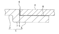
すると、樹脂製管継手1は、熱伸縮による繰返し応力によって、図7に示すように、疲労破壊を起こすおそれがある(疲労破壊部5)。このような樹脂製管継手1の疲労破壊は、図8に示すように、接着受口部3の内部における樹脂製管部材4の先端の位置6の周辺に多く生じる傾向がある。これは、上記位置6が、継手本体2と接着受口部3との境界部分に存在するフランジ部7(拡径部)と、樹脂製管部材4と接着受口部3との(接着剤による)接着部分8との間に挟まれることにより、全体としての肉厚が局所的に急減する形状(肉厚急減形状部)となっているため、応力集中が起こり易いことによるものと考えられる。   Then, as shown in FIG. 7, the resin pipe joint 1 may cause fatigue failure due to repeated stress due to thermal expansion and contraction (fatigue failure portion 5). As shown in FIG. 8, such fatigue failure of the resin pipe joint 1 tends to occur frequently around the position 6 at the tip of the resin pipe member 4 inside the adhesion receiving portion 3. This is because the position 6 includes a flange portion 7 (expanded diameter portion) existing at a boundary portion between the joint body 2 and the adhesive receiving portion 3, and the resin pipe member 4 and the adhesive receiving portion 3 (adhesive). It is considered that stress concentration is likely to occur because the overall thickness is sharply reduced locally by being sandwiched between the adhesive portion 8 and the adhesive portion 8. .

このような繰返しの熱伸縮による疲労破壊を防止するために、従来、受口部3の内部にゴムパッキンを備えて、このゴムパッキンにより、樹脂製管部材4を軸線方向へ移動自在に挿通保持しつつ止水可能となるようにした樹脂製管継手1が各種提案されている(例えば、特許文献1ないし特許文献4参照)。   In order to prevent such fatigue failure due to repeated thermal expansion and contraction, conventionally, a rubber packing has been provided inside the receiving portion 3, and the resin pipe member 4 is inserted and held movably in the axial direction by this rubber packing. Various types of resin pipe joints 1 that can stop water while being proposed have been proposed (for example, see Patent Documents 1 to 4).

また、このようなゴムパッキンを備えた樹脂製管継手1に対して、樹脂製管部材4の挿入位置を規定可能なストッパ部を備えることにより、受口部3に対する樹脂製管部材4の挿入過剰や挿入不足を起こさずに確実に施工し得るようにすることも行われている。更に、上記したストッパ部を、樹脂製管部材4の伸長時に樹脂製管部材4の先端が乗越可能となるように構成することなども行われている(特許文献3参照)。   In addition, the resin pipe joint 1 having such a rubber packing is provided with a stopper portion capable of defining the insertion position of the resin pipe member 4, thereby inserting the resin pipe member 4 into the receiving portion 3. It is also possible to reliably perform construction without causing excessive or insufficient insertion. Furthermore, the above-described stopper portion is configured such that the tip of the resin pipe member 4 can pass over when the resin pipe member 4 is extended (see Patent Document 3).

特開2009−2476号JP 2009-2476 特開2008−106862号JP 2008-106862 A 特開2006−312967号JP 2006-31967 A 特許第2604445号Patent No. 2604445

しかしながら、従来の管継手には、以下のような問題があった。   However, the conventional pipe joint has the following problems.

即ち、上記したような、単層構造の樹脂材料として構成された通常の接着接合型の樹脂製管継手1は、構造及び施工が簡単で安価である反面、樹脂製管部材4と同種の樹脂材料のみによって構成されていたため、上記した繰返しの熱伸縮を受ける肉厚急減形状部での疲労破壊を根本的に防止することができないという問題があった。   That is, the above-described ordinary adhesive-bonding type resin pipe joint 1 configured as a single-layer resin material is simple and inexpensive, while it is the same type of resin as the resin pipe member 4. Since it was composed only of the material, there was a problem that it was not possible to fundamentally prevent the fatigue failure at the thickness-reducing shape portion subjected to repeated thermal expansion and contraction.

また、ゴムパッキンやストッパ部などを備えることにより、繰返しの熱伸縮による疲労破壊に耐え得るようにした樹脂製管継手1は、上記した単層構造の樹脂材料からなる接着接合型の樹脂製管継手1と比べて、構造が複雑となり、価格も高価であると共に、ゴムパッキンの経年劣化による止水性低下が生じるという問題があった。   The resin pipe joint 1 provided with a rubber packing, a stopper portion, etc. so as to be able to withstand fatigue failure due to repeated thermal expansion and contraction is an adhesively bonded resin pipe made of the resin material having the single-layer structure described above. Compared with the joint 1, there are problems that the structure is complicated, the price is expensive, and the water stoppage is lowered due to the aging of the rubber packing.

上記課題を解決するために、請求項1に記載された発明は、短管状の継手本体と、継手本体の端部に設けられた複数の接着受口部とを有すると共に、該接着受口部が、樹脂製管部材の端部を挿入接着固定可能に構成された管継手部構造において、前記接着受口部は、その内層に、前記樹脂製管部材と接着接合可能な樹脂材料を有する複合受口部とされ、該複合受口部の外層と、前記継手本体とは、前記樹脂製管部材の熱伸縮応力を吸収可能な樹脂材料で構成されていることを特徴としている。   In order to solve the above-mentioned problem, the invention described in claim 1 has a short tubular joint body and a plurality of adhesive receptacles provided at the ends of the joint body, and the adhesive receptacles. However, in the pipe joint part structure configured to be capable of inserting and fixing the end part of the resin pipe member, the adhesive receiving part has a resin material that can be adhesively bonded to the resin pipe member in its inner layer. The outer portion of the composite receiving portion and the joint body are made of a resin material capable of absorbing the thermal expansion and contraction stress of the resin pipe member.

上記において、請求項2に記載された発明は、前記複合受口部の内層と外層とは、アンカー構造部を介して固定されていることを特徴としている。   In the above, the invention described in claim 2 is characterized in that an inner layer and an outer layer of the composite receiving portion are fixed via an anchor structure portion.

請求項1の発明によれば、上記構成によって、以下のような作用効果を得ることができる。即ち、接着受口部を複合受口部としたことにより、接着受口部の内層と外層とにそれぞれ異なる機能を持たせることが可能となる。また、複合受口部は、見掛上、通常の単層構造を有する接着受口部と全く同様の形状に仕上げることができるので、一般的な樹脂製管継手と同じに取扱ったり施工したりすることが可能となる。即ち、特別な取扱いや施工が不要となる。複合受口部は、その内層を構成する樹脂材料によって、樹脂製管部材を接着接合することが可能となる。   According to invention of Claim 1, the following effects can be acquired by the said structure. In other words, by using the composite receiving part as the adhesive receiving part, the inner layer and the outer layer of the adhesive receiving part can have different functions. In addition, the composite receiving part can be finished in the same shape as an adhesive receiving part having an ordinary single-layer structure, so it can be handled and constructed in the same way as a general resin pipe joint. It becomes possible to do. That is, no special handling or construction is required. The composite receiving part can be bonded and bonded to the resin pipe member by the resin material constituting the inner layer.

また、複合受口部の外層と、継手本体とを構成する樹脂材料によって、樹脂製管部材の熱伸縮応力を吸収することが可能となる。即ち、樹脂製管部材の熱伸縮に追随して、複合受口部や継手本体を伸縮または変形させることができるようになる。これにより、ゴムパッキンやストッパ部などを備えた複雑な構造とすることなく、単純な構成で、繰返しの熱伸縮による疲労破壊を防止することが可能となる。   Moreover, it becomes possible to absorb the thermal expansion-contraction stress of a resin pipe member by the resin material which comprises the outer layer of a composite opening part, and a coupling main body. That is, following the thermal expansion and contraction of the resin pipe member, the composite receiving portion and the joint main body can be expanded and contracted or deformed. Accordingly, it is possible to prevent fatigue failure due to repeated thermal expansion and contraction with a simple configuration without using a complicated structure including a rubber packing and a stopper portion.

請求項2の発明によれば、上記構成によって、以下のような作用効果を得ることができる。即ち、複合受口部の内層と外層とが、アンカー構造部を介して固定されていることにより、内層と外層との間に、一体的強度を保持することが可能となる。また、内層と外層との間の止水性を確保することも可能となる。   According to invention of Claim 2, the following effects can be acquired by the said structure. That is, since the inner layer and the outer layer of the composite receiving portion are fixed via the anchor structure portion, it is possible to maintain an integral strength between the inner layer and the outer layer. In addition, it is possible to ensure water-stopping between the inner layer and the outer layer.

本発明の実施例にかかる管継手部構造の斜視図である。It is a perspective view of the pipe joint part structure concerning the Example of this invention. 図1の管継手の複合受口部に樹脂製管部材を接着接合した管継手部構造の部分断面図である。FIG. 2 is a partial cross-sectional view of a pipe joint structure in which a resin pipe member is adhesively bonded to a composite receiving part of the pipe joint of FIG. 1. 図2の接着用受口部の内層部材の斜視図である。FIG. 3 is a perspective view of an inner layer member of the bonding port portion of FIG. 2. 接着用受口部の内層部材の変形例の斜視図である。It is a perspective view of the modification of the inner layer member of the receptacle part for adhesion | attachment. 接着用受口部の内層部材の他の変形例の斜視図である。It is a perspective view of the other modification of the inner layer member of the receptacle part for adhesion | attachment. 従来例にかかる管継手部構造の斜視図である。It is a perspective view of the pipe joint part structure concerning a prior art example. 図6に生じる疲労破壊の様子を示す斜視図である。It is a perspective view which shows the mode of the fatigue fracture which arises in FIG. 図7の部分断面図である。It is a fragmentary sectional view of FIG.

本発明は、主に、樹脂製管継手の熱伸縮による耐疲労破壊強度の向上を図り得るようにすることを目的としている。   An object of the present invention is to make it possible to improve the fatigue fracture resistance due to thermal expansion and contraction of a resin pipe joint.

以下、本発明を具体化した実施例について、図示例と共に説明する。   Hereinafter, embodiments embodying the present invention will be described together with illustrated examples.

図1〜図5は、この発明の実施例およびその変形例を示すものである。   1 to 5 show an embodiment of the present invention and a modification thereof.

<構成>まず、構成について説明する。   <Configuration> First, the configuration will be described.

図1に示すような、樹脂製管継手1は、図2に示すように、樹脂製管部材4の接着接続(接着剤による接着部分8参照)に使用可能なものである。この樹脂製管継手1は、短管状の継手本体2と、継手本体2の端部に設けられた複数の接着受口部3とを有している。そして、樹脂製管継手1の接着受口部3に対して、樹脂製管部材4の端部を挿入接着固定することにより、樹脂製管部材4の接続を容易に行い得るように構成する。   As shown in FIG. 2, the resin pipe joint 1 as shown in FIG. 1 can be used for adhesive connection of the resin pipe member 4 (see the adhesive portion 8 using an adhesive). The resin pipe joint 1 includes a short tubular joint body 2 and a plurality of adhesive receiving portions 3 provided at the end of the joint body 2. And it connects so that the resin pipe member 4 can be connected easily by inserting and fixing the edge part of the resin pipe member 4 with respect to the adhesion receiving part 3 of the resin pipe joint 1.

ここで、接着受口部3は、継手本体2に対し、フランジ部7(拡径部)を介して拡径形成される。継手本体2は、その内径が、樹脂製管部材4の内径とほぼ等しくなるように構成される。また、接着受口部3は、全体として、その内径が、樹脂製管部材4の外径とほぼ等しくなるように構成される。   Here, the diameter of the adhesive receiving port 3 is increased with respect to the joint main body 2 via the flange portion 7 (expanded diameter portion). The joint body 2 is configured such that its inner diameter is substantially equal to the inner diameter of the resin pipe member 4. In addition, the adhesive receiving port 3 as a whole is configured such that its inner diameter is substantially equal to the outer diameter of the resin pipe member 4.

このような樹脂製管継手1には、例えば、図示のようなLT型のもの(接着受口部3を3箇所有するもの)や、特に図示しないL型のもの(接着受口部3を2箇所有するもの)など、各種のものが存在している。上記したLT型の樹脂製管継手1は、継手本体2に、直線部分と分岐・合流部分とを有している。また、L型の樹脂製管継手1は、継手本体2に、屈曲部分を有している。   Examples of such a resin pipe joint 1 include, for example, an LT type as shown (having three adhesion receiving portions 3), and an L type (not shown) having two bonding receiving portions 3 (not shown). There are various kinds of things such as those having places. The above-described LT-type resin pipe joint 1 has a straight part and a branch / merging part in the joint body 2. The L-shaped resin pipe joint 1 has a bent portion in the joint body 2.

このような樹脂製管部材4や樹脂製管継手1は、例えば、住宅やマンションなどの建築物の排水設備や給水給湯設備などの配管部などに用いられる。この場合、配管部の内部を流れる流体の温度や、外気温の影響などにより、樹脂製管継手1は樹脂製管部材4と共に熱伸縮を繰返すことになる。この樹脂製管部材4や樹脂製管継手1の熱伸縮は、配管部の上流側に設けられるもの程、大きくなる傾向にある。   Such a resin pipe member 4 and the resin pipe joint 1 are used, for example, in a piping section of a drainage facility or a water supply / hot water supply facility of a building such as a house or a condominium. In this case, the resin pipe joint 1 repeats thermal expansion and contraction together with the resin pipe member 4 due to the temperature of the fluid flowing inside the piping part, the influence of the outside air temperature, and the like. The thermal expansion and contraction of the resin pipe member 4 and the resin pipe joint 1 tends to be larger as it is provided on the upstream side of the pipe portion.

そして、以上のような基本的な構成に対し、この実施例のものでは、以下のような構成を備えるようにしている。   In addition to the basic configuration as described above, the present embodiment has the following configuration.

(1)接着受口部3は、その内層12に、樹脂製管部材4と接着接合可能な樹脂材料14(以下、必要に応じて接着用樹脂材料14という)を有すると共に、その外層13に、上記樹脂材料14とは異なる樹脂材料15(以下、必要に応じて異種樹脂材料15という)を有する複合受口部11とされる。そして、特に、この複合受口部11の外層13と、継手本体2とが、樹脂製管部材4の熱伸縮応力を吸収可能な樹脂材料18(以下、必要に応じて伸縮性樹脂材料18という)で構成される。   (1) The adhesive receptacle 3 has a resin material 14 (hereinafter referred to as an adhesive resin material 14 as necessary) on the inner layer 12 thereof and an outer layer 13 on the inner layer 12 thereof. The composite receiving portion 11 has a resin material 15 different from the resin material 14 (hereinafter referred to as a different resin material 15 if necessary). In particular, the outer layer 13 of the composite receiving portion 11 and the joint body 2 are capable of absorbing the thermal expansion and contraction stress of the resin pipe member 4 (hereinafter referred to as the elastic resin material 18 as necessary). ).

ここで、内層12を構成する接着用樹脂材料14は、樹脂製管部材4と同種の樹脂材料を用いるのが好ましい。   Here, it is preferable to use the same kind of resin material as that of the resin pipe member 4 as the adhesive resin material 14 constituting the inner layer 12.

例えば、樹脂製管部材4が塩化ビニル樹脂製である場合、接着用樹脂材料14は、同じく塩化ビニル樹脂製とする。より具体的には、例えば、接着用樹脂材料14を、塩化ビニル重合体、または、塩化ビニルを主体とする共重合体などによって構成する。   For example, when the resin pipe member 4 is made of vinyl chloride resin, the adhesive resin material 14 is also made of vinyl chloride resin. More specifically, for example, the adhesive resin material 14 is made of a vinyl chloride polymer or a copolymer mainly composed of vinyl chloride.

この内層12を構成する接着用樹脂材料14は、その内径が、樹脂製管部材4の外径とほぼ等しく、その外径が、外層13の内径とほぼ等しい短筒状のものとなるように構成する。また、短筒状の内層12の内方端には、応力低減構造部として、上記したフランジ部7の内面部分を構成する(内向き)フランジ部16などを設けるようにしても良い。   The adhesive resin material 14 constituting the inner layer 12 has a short cylindrical shape whose inner diameter is substantially equal to the outer diameter of the resin pipe member 4 and whose outer diameter is substantially equal to the inner diameter of the outer layer 13. Constitute. Moreover, you may make it provide the flange part 16 etc. which comprise the inner surface part of the above-mentioned flange part 7 as an stress reduction structure part in the inner end of the short cylinder-shaped inner layer 12.

そして、外層13を構成する異種樹脂材料15を、樹脂製管部材4の熱伸縮に追随して伸縮または変形可能な伸縮性樹脂材料18とする。   The dissimilar resin material 15 constituting the outer layer 13 is made an elastic resin material 18 that can expand or contract following the thermal expansion and contraction of the resin pipe member 4.

ここで、伸縮性樹脂材料18は、弾性率が低く、引張破断歪が大きい樹脂材料を用いるのが好ましい。このように、弾性率の低い樹脂材料を用いることにより、熱伸縮によって発生する応力を、構造的に低減させることが可能となる。弾性率については、概ね、一般的な単層構造の樹脂材料からなる樹脂製管継手1の1/3程度以下となるようにするのが、有効に機能させる上では好ましい。また、引張破断歪の大きい樹脂材料を用いることにより、変形や変位に対する追随性を構造的に向上させることが可能となる。引張破断歪については、概ね、一般的な単層構造の樹脂材料からなる樹脂製管継手1の2倍以上となるようにするのが、有効に機能させる上では好ましい。   Here, the elastic resin material 18 is preferably a resin material having a low elastic modulus and a large tensile breaking strain. Thus, by using a resin material having a low elastic modulus, it is possible to structurally reduce the stress generated by thermal expansion and contraction. The elastic modulus is preferably about 1/3 or less of the resin pipe joint 1 made of a resin material having a general single layer structure in order to function effectively. Further, by using a resin material having a large tensile fracture strain, it is possible to structurally improve the followability to deformation and displacement. The tensile breaking strain is preferably at least twice that of a resin pipe joint 1 made of a resin material having a general single-layer structure in order to function effectively.

例えば、樹脂製管部材4が塩化ビニル樹脂製である場合、伸縮性樹脂材料18は、ポリプロピレン樹脂やポリエチレン樹脂などとする。より具体的には、例えば、伸縮性樹脂材料18を、プロピレン重合体、または、プロピレンを主体とする共重合体などで構成する。   For example, when the resin pipe member 4 is made of vinyl chloride resin, the stretchable resin material 18 is made of polypropylene resin or polyethylene resin. More specifically, for example, the stretchable resin material 18 is composed of a propylene polymer or a copolymer mainly composed of propylene.

そして、伸縮性樹脂材料18が、樹脂製管部材4の熱伸縮に追随して、有効に伸縮または変形し得るようにするためには、伸縮性樹脂材料18は、樹脂製管部材4の伸縮量と等しいか、それ以上の伸縮量を有するものとする。樹脂製管部材4の伸縮量は、樹脂製管部材4の長さと、熱膨張(熱収縮)係数との積を基準として求めることができる。   In order for the stretchable resin material 18 to effectively expand and contract following the thermal expansion and contraction of the resin tube member 4, the stretchable resin material 18 is made to expand and contract the resin tube member 4. The amount of expansion / contraction is equal to or greater than the amount. The amount of expansion / contraction of the resin pipe member 4 can be obtained on the basis of the product of the length of the resin pipe member 4 and the thermal expansion (thermal contraction) coefficient.

より具体的には、例えば、塩化ビニル樹脂製の場合、樹脂製管部材4の長さを、樹脂製管部材4の規格寸法の1つである4mに想定した場合、樹脂製管部材4の伸縮量は、約20mmとなる。そのため、継手本体2の直線部分の両端に、対向する2箇所の複合受口部11を有するT型やLT型の樹脂製管継手1の場合、2箇所合わせて最大約40mmの伸縮量を有することが必要となる。よって、伸縮性樹脂材料18は、引抜試験による破壊時の伸縮量が40mm以上となるように構成するのが好ましい。そして、40mm以上の伸縮量を得るためには、複合受口部11の外層13だけでは伸縮量が不足するので、継手本体2の直線部分の伸縮量も利用し得るようにする。そのために、上記したように、複合受口部11の外層13と継手本体2とフランジ部7とを含めた樹脂製管継手1のほぼ全体(但し、内層12を除く)を伸縮性樹脂材料18によって構成する。この場合、継手本体2と複合受口部11との境界となるフランジ部7には、応力集中が生じ難いようにするために、上記とは別の応力低減構造部として、通常のものよりも大きめの(即ち、応力集中を有効に低減できる程度の曲率の)アール部21(大型アール部)などを形成しておくようにするのが好ましい。このような構成とすることにより、最も熱伸縮の激しい上流側の樹脂製管継手1として採用することなども可能となる。   More specifically, for example, in the case of a product made of vinyl chloride resin, when the length of the resin tube member 4 is assumed to be 4 m which is one of the standard dimensions of the resin tube member 4, the resin tube member 4 The amount of expansion / contraction is about 20 mm. Therefore, in the case of a T-type or LT-type resin pipe joint 1 having two opposing composite receiving portions 11 at both ends of the straight portion of the joint body 2, the maximum amount of expansion and contraction is about 40 mm when the two places are combined. It will be necessary. Therefore, it is preferable that the stretchable resin material 18 is configured such that the amount of stretch at the time of breakage in the pull-out test is 40 mm or more. And in order to obtain the amount of expansion and contraction of 40 mm or more, the amount of expansion and contraction is insufficient only with the outer layer 13 of the composite receiving portion 11, so that the amount of expansion and contraction of the straight portion of the joint body 2 can also be used. Therefore, as described above, almost all of the resin pipe joint 1 including the outer layer 13, the joint body 2, and the flange portion 7 of the composite receiving portion 11 (excluding the inner layer 12) is made of the stretchable resin material 18. Consists of. In this case, in order to make it difficult for stress concentration to occur in the flange portion 7 which is the boundary between the joint body 2 and the composite receiving portion 11, as a stress reduction structure portion different from the above, it is more than a normal one. It is preferable to form a larger round portion 21 (ie, a large round portion) having a large curvature (that is, a curvature that can effectively reduce stress concentration). By adopting such a configuration, it is possible to employ the pipe joint 1 made of the upstream side with the most severe thermal expansion and contraction.

(2)更に、上記した複合受口部11の内層12と外層13とは、固定部25を介して固定される。   (2) Furthermore, the inner layer 12 and the outer layer 13 of the above-described composite receiving portion 11 are fixed via the fixing portion 25.

ここで、固定部25は、内層12の外周面と、外層13の内周面との間を、軸線方向および周方向に対して、固定し得るようにするものである。   Here, the fixing | fixed part 25 can fix between the outer peripheral surface of the inner layer 12, and the inner peripheral surface of the outer layer 13 with respect to an axial direction and a circumferential direction.

また、固定部25は、内層12にフランジ部16を設けた場合には、上記したフランジ部7の内面と、フランジ部16の外面との間に対して、設けることができる。この場合、固定部25は、フランジ部7の内面と、フランジ部16の外面とを、軸線方向および周方向に対して、固定し得るようにするものとなる。   Further, when the flange portion 16 is provided on the inner layer 12, the fixing portion 25 can be provided between the inner surface of the flange portion 7 and the outer surface of the flange portion 16. In this case, the fixing portion 25 can fix the inner surface of the flange portion 7 and the outer surface of the flange portion 16 in the axial direction and the circumferential direction.

そして、この固定部25を、上記したアンカー構造部28とする。このアンカー構造部28は、例えば、内層12と外層13との間に、凹凸形状部29を設けることによって構成する。凹凸形状部29は、アンカー構造部28として有効に機能可能な形状や凹凸量(または突出量)を有するものとされる。   The fixing portion 25 is referred to as the anchor structure portion 28 described above. The anchor structure portion 28 is configured by, for example, providing an uneven shape portion 29 between the inner layer 12 and the outer layer 13. The uneven portion 29 has a shape and an uneven amount (or protruding amount) that can function effectively as the anchor structure portion 28.

このような、凹凸形状部29は、例えば、図2に示すように、複合受口部11の周方向へ延びる環状凹部32と、この環状凹部32に隙間なく嵌合可能な環状凸部33との組合せとすることができる。この環状凹部32と、環状凸部33とは、複合受口部11の軸線方向に対し、最適な間隔を有して複数段に設けることができる。この場合、外層13に環状凹部32が設けられ、図3に示すように、内層12に環状凸部33が設けられるようにしている。但し、これらは、反対に設けても良い。即ち、外層13に環状凸部33を設けて、内層12に環状凹部32を設けるようにしても良い。   For example, as shown in FIG. 2, the uneven portion 29 has an annular recess 32 that extends in the circumferential direction of the composite receiving portion 11, and an annular protrusion 33 that can be fitted into the annular recess 32 without a gap. Can be combined. The annular concave portion 32 and the annular convex portion 33 can be provided in a plurality of stages with an optimal interval with respect to the axial direction of the composite receiving portion 11. In this case, an annular recess 32 is provided in the outer layer 13, and an annular protrusion 33 is provided in the inner layer 12, as shown in FIG. However, these may be provided in reverse. That is, the annular protrusion 33 may be provided on the outer layer 13 and the annular recess 32 may be provided on the inner layer 12.

同様の凹凸形状部29は、フランジ部7の内面と、フランジ部16の外面との間に設けることができる。この場合、フランジ部7の内面に環状凸部33が設けられ、フランジ部16の外面に環状凹部32が設けられるようにしている。但し、これらは、反対に設けても良い。即ち、フランジ部7の内面に環状凹部32が設けられ、フランジ部16の外面に環状凸部33が設けられるようにしても良い。なお、凹凸形状部29の凹凸の向き(突出方向)は、構造上、内層12と外層13との間では、半径方向となるのに対し、フランジ部7とフランジ部16との間では、軸線方向となる。   The same uneven portion 29 can be provided between the inner surface of the flange portion 7 and the outer surface of the flange portion 16. In this case, an annular convex portion 33 is provided on the inner surface of the flange portion 7, and an annular concave portion 32 is provided on the outer surface of the flange portion 16. However, these may be provided in reverse. That is, the annular concave portion 32 may be provided on the inner surface of the flange portion 7 and the annular convex portion 33 may be provided on the outer surface of the flange portion 16. Note that the direction of protrusions and recesses (projection direction) of the uneven portion 29 is structurally a radial direction between the inner layer 12 and the outer layer 13, whereas an axis line between the flange portion 7 and the flange portion 16. Direction.

この場合、環状凸部33は、環状凹部32が設けられる部材(内層12または外層13、フランジ部16)の肉厚のほぼ半分程度の突出量を有するものなどとされている。なお、フランジ部7周辺の強度低下を防止し得るようにするために、環状凸部33または環状凹部32は、継手本体2と複合受口部11との境界となるフランジ部7から(強度低下防止に必要な距離だけ)軸線方向に離して設けるようにするのが好ましい(強度低下防止用距離または軸線方向距離34)。   In this case, the annular convex portion 33 has a protruding amount that is approximately half the thickness of the member (the inner layer 12 or the outer layer 13 or the flange portion 16) in which the annular concave portion 32 is provided. In order to prevent a decrease in strength around the flange portion 7, the annular convex portion 33 or the annular concave portion 32 is separated from the flange portion 7 that becomes a boundary between the joint body 2 and the composite receiving portion 11 (reduced strength). It is preferable that they are provided apart in the axial direction (only the distance necessary for prevention) (strength for preventing strength reduction or axial distance 34).

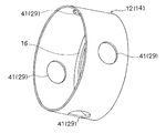
また、凹凸形状部29は、例えば、図4に示したものからも分かるように、開口部41と、この開口部41に対して隙間なく嵌合可能な嵌合凸部(図示せず)とすることができる。この開口部41と嵌合凸部とは、複合受口部11の周方向に対し、最適な間隔を有して複数個設けることができる。この場合、外層13に嵌合凸部が設けられ、内層12に開口部41が設けられるようにしている。但し、開口部41と嵌合凸部とは、反対に設けても良い。即ち、外層13に開口部41を設け、内層12に嵌合凸部を設けるようにしても良い。また、各開口部41と嵌合凸部との設置個数や大きさなどは、最適に設定することができる。   In addition, as shown in FIG. 4, for example, the uneven portion 29 has an opening 41 and a fitting convex portion (not shown) that can be fitted to the opening 41 without a gap. can do. A plurality of the opening portions 41 and the fitting convex portions can be provided with an optimal interval in the circumferential direction of the composite opening portion 11. In this case, the outer layer 13 is provided with a fitting convex portion, and the inner layer 12 is provided with an opening 41. However, you may provide the opening part 41 and a fitting convex part in reverse. That is, the opening 41 may be provided in the outer layer 13 and the fitting convex portion may be provided in the inner layer 12. Further, the number and size of the openings 41 and the fitting protrusions can be set optimally.

この場合、嵌合凸部は、開口部41が設けられる部材(内層12または外層13)の肉厚とほぼ等しい突出量を有するものとされている。また、開口部41と嵌合凸部とは、複合受口部11の周方向に対し、90度の位相を有して4箇所設けられている。各開口部41と嵌合凸部とは、円形状をしている。但し、各開口部41と嵌合凸部とは、円形状以外の形状することができる。   In this case, the fitting convex part has a protruding amount substantially equal to the thickness of the member (inner layer 12 or outer layer 13) in which the opening 41 is provided. Further, the opening 41 and the fitting convex portion are provided at four places with a phase of 90 degrees with respect to the circumferential direction of the composite opening portion 11. Each opening 41 and the fitting convex part are circular. However, each opening part 41 and the fitting convex part can have shapes other than circular shape.

また、凹凸形状部29は、例えば、図5に示したものからも分かるように、嵌合凹部と、この嵌合凹部に隙間なく嵌合可能な嵌合凸部43とすることができる。この嵌合凹部と嵌合凸部43とは、複合受口部11の周方向に対し、最適な間隔を有して複数個設けることができる。この場合、外層13に嵌合凹部が設けられ、内層12に嵌合凸部43が設けられるようにしている。但し、嵌合凹部と嵌合凸部43とは、反対に設けても良い。即ち、外層13に嵌合凸部43を設け、内層12に嵌合凹部を設けるようにしても良い。また、各嵌合凹部と嵌合凸部43との設置個数や大きさなどについては、最適に設定することができる。   Moreover, the uneven | corrugated shaped part 29 can be used as the fitting recessed part and the fitting convex part 43 which can be fitted to this fitting recessed part without gap so that it may understand also from what was shown in FIG. A plurality of the fitting concave portions and the fitting convex portions 43 can be provided with an optimum interval in the circumferential direction of the composite opening portion 11. In this case, the outer layer 13 is provided with a fitting concave portion, and the inner layer 12 is provided with a fitting convex portion 43. However, the fitting concave portion and the fitting convex portion 43 may be provided opposite to each other. That is, the fitting convex portion 43 may be provided on the outer layer 13 and the fitting concave portion may be provided on the inner layer 12. In addition, the number and size of the fitting recesses and the fitting protrusions 43 can be set optimally.

この場合、嵌合凸部43は、嵌合凹部が設けられる部材(内層12または外層13)の肉厚のほぼ半分程度の突出量を有するものとされている。この嵌合凹部と嵌合凸部43とは、複合受口部11の周方向に対し、90度の位相を有して4箇所設けられている。各嵌合凹部と嵌合凸部43とは、矩形状をしている。但し、各嵌合凹部と嵌合凸部43とは、矩形状以外の形状としても良い。   In this case, the fitting convex portion 43 has a protruding amount that is approximately half the thickness of the member (inner layer 12 or outer layer 13) provided with the fitting concave portion. The fitting concave portion and the fitting convex portion 43 are provided at four positions with a phase of 90 degrees with respect to the circumferential direction of the composite opening portion 11. Each fitting recessed part and the fitting convex part 43 are carrying out the rectangular shape. However, each fitting recessed part and the fitting convex part 43 are good also as shapes other than rectangular shape.

更に、凹凸形状部29は、特に図示しないが、ネジ孔と、ネジ溝との組合せなどとすることもできる。或いは、凹凸形状部29は、特に図示しないが、網目状やローレット加工模様などにすることもできる。   Furthermore, although the uneven portion 29 is not particularly illustrated, it can be a combination of a screw hole and a screw groove. Or although the uneven | corrugated shaped part 29 is not specifically illustrated, it can also be made into a mesh shape, a knurled pattern, etc.

更にまた、アンカー構造部28は、接着と組合せることもできる。この場合、接着は、接着剤を用いるもの(接着剤による接着)や、製造時(成形時)に発生する熱を利用するもの(熱接着)などが利用できる。   Furthermore, the anchor structure 28 can also be combined with adhesion. In this case, the bonding can be performed using an adhesive (adhesion using an adhesive) or using heat generated during manufacturing (molding) (thermal bonding).

(3)樹脂製管継手1の製造について
上記した複合受口部11の内層12と、継手本体2および複合受口部11の外層13とは、それぞれ射出成形によって成形されるようにする。
(3) Production of Resin Pipe Fitting 1 The inner layer 12 of the composite receiving part 11 and the outer layer 13 of the joint body 2 and the composite receiving part 11 are each formed by injection molding.

この場合において、樹脂製管継手1は、インサート成形によって成形することができる。インサート成形の場合には、予め射出成形された接着用樹脂材料14による内層12を金型にセットしてから、金型に伸縮性樹脂材料18を注入して継手本体2および外層13を射出成形する。   In this case, the resin pipe joint 1 can be formed by insert molding. In the case of insert molding, the inner layer 12 made of an adhesive resin material 14 that has been injection-molded in advance is set in a mold, and then a stretchable resin material 18 is injected into the mold to injection-mold the joint body 2 and the outer layer 13. To do.

また、樹脂製管継手1は、二色成形(多色成形)によって成形することができる。二色成形(多色成形)とする場合には、一種類の金型に対し、別々に樹脂を射出可能な複数の射出ノズルを用いて、上記した内層12と、継手本体2および外層13とを同時に射出形成する。   The resin pipe joint 1 can be molded by two-color molding (multicolor molding). In the case of two-color molding (multicolor molding), the inner layer 12, the joint body 2, and the outer layer 13 described above are used for one type of mold by using a plurality of injection nozzles capable of separately injecting resin. The injection molding at the same time.

或いは、内層12と、継手本体2および外層13とを別々に射出成形しておき、後工程で両者を嵌合または強制嵌合するなどにより組合せて固定し、樹脂製管継手1を構成することなども可能である。   Alternatively, the inner layer 12, the joint body 2 and the outer layer 13 are separately injection-molded, and fixed in combination by, for example, fitting or forcibly fitting the two in a later process to constitute the resin pipe joint 1. Etc. are also possible.

なお、樹脂製管継手1を、上記したインサート成形や二色成形(多色成形)で製造する場合には、アンカー構造部28に対し、熱接着が行われることになる。また、樹脂製管継手1を上記した嵌合または強制嵌合で製造する場合には、アンカー構造部28に対し、接着剤で接着するようにしても良い。なお、上記したインサート成形の場合には、内層12に接着剤を塗布して置くことも可能である。   When the resin pipe joint 1 is manufactured by the above-described insert molding or two-color molding (multicolor molding), the anchor structure portion 28 is thermally bonded. Further, when the resin pipe joint 1 is manufactured by the above-described fitting or forced fitting, it may be bonded to the anchor structure portion 28 with an adhesive. In the case of the insert molding described above, an adhesive can be applied to the inner layer 12 and placed.

(4)樹脂製管継手1の着色について
上記した内層12と、継手本体2および外層13とは、どちらか一方または両方を、非透明または透明のものとすることができる。内層12と、継手本体2および外層13との両方を透明とした場合には、樹脂製管継手1の内部の様子を外側から観察し得るものとなる。これにより、透明な樹脂製管継手1によって、樹脂製管部材4の施工状況や配管部の使用状況を確認することが可能となる。また、内層12と、継手本体2および外層13との両方を非透明とした場合には、通常の単層構造の樹脂製管継手1と外観上同じように仕上げることが可能となる。また、目的や用途によって、内層12と、継手本体2および外層13との一方を非透明とし、他方を透明とすることなども可能となる。
(4) Coloring of the resin pipe joint 1 Either or both of the inner layer 12, the joint body 2 and the outer layer 13 described above can be made non-transparent or transparent. When both the inner layer 12 and the joint body 2 and the outer layer 13 are transparent, the inside of the resin pipe joint 1 can be observed from the outside. Thereby, it becomes possible to confirm the construction status of the resin pipe member 4 and the usage status of the piping portion by the transparent resin pipe joint 1. Further, when both the inner layer 12 and the joint body 2 and the outer layer 13 are made non-transparent, it is possible to finish in the same manner as the resin pipe joint 1 having a normal single layer structure. Also, depending on the purpose and application, it is possible to make one of the inner layer 12, the joint body 2 and the outer layer 13 non-transparent and the other transparent.

<作用>次に、この実施例の作用について説明する。   <Operation> Next, the operation of this embodiment will be described.

接着受口部3が複合受口部11とされた樹脂製管継手1は、上記したように、インサート成形や、二色成形(多色成形)や、内層12と、外層13との嵌合または強制嵌合などによって製造される。   As described above, the resin pipe joint 1 in which the adhesive receiving portion 3 is the composite receiving portion 11 is formed by insert molding, two-color molding (multicolor molding), or fitting between the inner layer 12 and the outer layer 13. Or it is manufactured by forced fitting or the like.

そして、この樹脂製管継手1は、例えば、住宅やマンションなどの建築物の排水設備や給水給湯設備などの配管部に用いられる。   And this resin pipe joint 1 is used for piping parts, such as a drainage facility of buildings, such as a house and a condominium, and a water supply hot-water supply equipment, for example.

即ち、この樹脂製管継手1の接着受口部3に対して、樹脂製管部材4の端部を挿入接着固定することにより、樹脂製管部材4の接続が行われる。この際、樹脂製管部材4の端部は、複合受口部11の内層12の接着用樹脂材料14に対して挿入接着固定される。   That is, the resin pipe member 4 is connected by inserting, fixing, and fixing the end of the resin pipe member 4 to the adhesion receiving portion 3 of the resin pipe joint 1. At this time, the end portion of the resin pipe member 4 is inserted and fixed to the adhesive resin material 14 of the inner layer 12 of the composite opening 11.

この実施例によれば、以下のような作用効果を得ることができる。   According to this embodiment, the following operational effects can be obtained.

(1)接着受口部3を複合受口部11としたことにより、接着受口部3の内層12と外層13とにそれぞれ異なる機能を持たせることが可能となる。また、複合受口部11は、見掛上、通常の単層構造を有する接着受口部と全く同様の形状に仕上げることができるので、一般的な樹脂製管継手と同じに取扱ったり施工したりすることが可能となる。即ち、特別な取扱いや施工が不要となる。複合受口部11は、その内層12を構成する樹脂材料14(接着用樹脂材料14)によって、樹脂製管部材4を接着接合することが可能となる。   (1) By using the adhesive receiving port 3 as the composite receiving port 11, the inner layer 12 and the outer layer 13 of the bonding receiving port 3 can have different functions. In addition, the composite receiving portion 11 can be finished in the same shape as an adhesive receiving portion having a normal single-layer structure, so that it is handled and constructed in the same manner as a general resin pipe joint. It becomes possible to do. That is, no special handling or construction is required. The composite receiving portion 11 can be bonded and bonded to the resin pipe member 4 by the resin material 14 (adhesive resin material 14) constituting the inner layer 12 thereof.

また、複合受口部11の外層13と、継手本体2とを構成する樹脂材料18(伸縮性樹脂材料18)によって、樹脂製管部材4の熱伸縮応力を吸収することが可能となる。即ち、樹脂製管部材4の熱伸縮に追随して、複合受口部11や継手本体2を伸縮または変形させることができるようになる。これにより、ゴムパッキンやストッパ部などを備えた複雑な構造とすることなく、単純な構成で、繰返しの熱伸縮による疲労破壊を防止することが可能となる。   Further, the resin material 18 (stretchable resin material 18) constituting the outer layer 13 of the composite receiving portion 11 and the joint body 2 can absorb the thermal expansion and contraction stress of the resin pipe member 4. That is, following the thermal expansion and contraction of the resin pipe member 4, the composite receiving portion 11 and the joint body 2 can be expanded and contracted or deformed. Accordingly, it is possible to prevent fatigue failure due to repeated thermal expansion and contraction with a simple configuration without using a complicated structure including a rubber packing and a stopper portion.

(2)複合受口部11の内層12と外層13とが、アンカー構造部28を介して固定されていることにより、内層12と外層13との間に、一体的強度を保持することが可能となる。また、内層12と外層13との間の止水性を確保することも可能となる。   (2) Since the inner layer 12 and the outer layer 13 of the composite receiving portion 11 are fixed via the anchor structure portion 28, it is possible to maintain an integral strength between the inner layer 12 and the outer layer 13. It becomes. In addition, it is possible to ensure water blocking between the inner layer 12 and the outer layer 13.

例えば、住宅やマンションなどの建築物の排水設備や給水給湯設備などの配管部に対し、熱伸縮による耐疲労破壊強度の高い樹脂製管継手を提供することができるようになる。   For example, it becomes possible to provide a resin pipe joint having a high fatigue resistance against fatigue due to thermal expansion and contraction for piping parts such as a drainage facility and a hot water supply facility for buildings such as houses and condominiums.

2 継手本体
3 接着受口部
4 樹脂製管部材
11 複合受口部
12 内層
13 外層
14 樹脂材料(接着用樹脂材料)
15 樹脂材料(伸縮性樹脂材料または異種樹脂材料)
18 樹脂材料(伸縮性樹脂材料)
28 アンカー構造部
2 Joint body 3 Adhesive receiving portion 4 Resin pipe member 11 Composite receiving portion 12 Inner layer 13 Outer layer 14 Resin material (adhesive resin material)
15 Resin material (stretchable resin material or dissimilar resin material)
18 Resin material (stretchable resin material)
28 Anchor structure

Claims (2)

短管状の継手本体と、継手本体の端部に設けられた複数の接着受口部とを有すると共に、該接着受口部が、樹脂製管部材の端部を挿入接着固定可能に構成された管継手部構造において、
前記接着受口部は、その内層に、前記樹脂製管部材と接着接合可能な樹脂材料を有する複合受口部とされ、
該複合受口部の外層と、前記継手本体とは、前記樹脂製管部材の熱伸縮応力を吸収可能な樹脂材料で構成されていることを特徴とする管継手部構造。
It has a short tubular joint body and a plurality of adhesive receiving portions provided at the end of the joint main body, and the adhesive receiving portion is configured so that the end of the resin pipe member can be inserted, bonded and fixed. In the pipe joint structure,
The adhesive receiving portion is a composite receiving portion having a resin material that can be adhesively bonded to the resin pipe member on the inner layer thereof,
An outer layer of the composite receiving part and the joint body are made of a resin material capable of absorbing thermal expansion and contraction stress of the resin pipe member.
前記複合受口部の内層と外層とは、アンカー構造部を介して固定されていることを特徴とする請求項1記載の管継手部構造。   The pipe joint part structure according to claim 1, wherein an inner layer and an outer layer of the composite receiving part are fixed via an anchor structure part.
JP2009145024A 2009-06-18 2009-06-18 Pipe joint structure Pending JP2011002012A (en)

Priority Applications (1)

Application Number Priority Date Filing Date Title
JP2009145024A JP2011002012A (en) 2009-06-18 2009-06-18 Pipe joint structure

Applications Claiming Priority (1)

Application Number Priority Date Filing Date Title
JP2009145024A JP2011002012A (en) 2009-06-18 2009-06-18 Pipe joint structure

Publications (1)

Publication Number Publication Date
JP2011002012A true JP2011002012A (en) 2011-01-06

Family

ID=43560135

Family Applications (1)

Application Number Title Priority Date Filing Date
JP2009145024A Pending JP2011002012A (en) 2009-06-18 2009-06-18 Pipe joint structure

Country Status (1)

Country Link
JP (1) JP2011002012A (en)

Cited By (12)

* Cited by examiner, † Cited by third party
Publication number Priority date Publication date Assignee Title
JP2018169005A (en) * 2017-03-30 2018-11-01 積水化学工業株式会社 Pipe joint
KR20190007174A (en) * 2017-07-12 2019-01-22 박순형 Freezing prevent type drainwater pipe connector structure
JP2019065949A (en) * 2017-09-29 2019-04-25 積水化学工業株式会社 Joint, piping structure, and manufacturing method of joint
JP2019065953A (en) * 2017-09-29 2019-04-25 積水化学工業株式会社 Joint, piping structure, and manufacturing method of joint
JP2020165449A (en) * 2019-03-28 2020-10-08 積水化学工業株式会社 Fitting and plumbing system
JP2020165528A (en) * 2019-03-28 2020-10-08 積水化学工業株式会社 Fittings and plumbing systems
JP2021148277A (en) * 2020-03-23 2021-09-27 積水化学工業株式会社 Pipe joint, piping and piping system
JP2021167655A (en) * 2020-04-13 2021-10-21 積水化学工業株式会社 Pipe joint, piping and piping system
JP2022049982A (en) * 2020-09-17 2022-03-30 積水化学工業株式会社 Pipe joint, piping and piping system
JP2022052227A (en) * 2020-09-23 2022-04-04 積水化学工業株式会社 Receptacle member for multilayer joint, multilayer joint and piping system
JP2022056949A (en) * 2020-09-30 2022-04-11 積水化学工業株式会社 Multilayer joint and piping system
US11530309B2 (en) 2017-09-29 2022-12-20 Sekisui Chemical Co., Ltd. Foamed resin molded article

Cited By (19)

* Cited by examiner, † Cited by third party
Publication number Priority date Publication date Assignee Title
JP2018169005A (en) * 2017-03-30 2018-11-01 積水化学工業株式会社 Pipe joint
KR102037574B1 (en) * 2017-07-12 2019-10-28 박순형 Freezing prevent type drainwater pipe connector structure
KR20190007174A (en) * 2017-07-12 2019-01-22 박순형 Freezing prevent type drainwater pipe connector structure
US11530309B2 (en) 2017-09-29 2022-12-20 Sekisui Chemical Co., Ltd. Foamed resin molded article
JP2019065949A (en) * 2017-09-29 2019-04-25 積水化学工業株式会社 Joint, piping structure, and manufacturing method of joint
JP2019065953A (en) * 2017-09-29 2019-04-25 積水化学工業株式会社 Joint, piping structure, and manufacturing method of joint
JP2020165449A (en) * 2019-03-28 2020-10-08 積水化学工業株式会社 Fitting and plumbing system
JP2020165528A (en) * 2019-03-28 2020-10-08 積水化学工業株式会社 Fittings and plumbing systems
JP7538594B2 (en) 2019-03-28 2024-08-22 積水化学工業株式会社 Fittings and Piping Systems
JP7453746B2 (en) 2019-03-28 2024-03-21 積水化学工業株式会社 fittings and piping systems
JP2021148277A (en) * 2020-03-23 2021-09-27 積水化学工業株式会社 Pipe joint, piping and piping system
JP7642316B2 (en) 2020-03-23 2025-03-10 積水化学工業株式会社 Pipe fittings, piping and piping systems
JP2021167655A (en) * 2020-04-13 2021-10-21 積水化学工業株式会社 Pipe joint, piping and piping system
JP2022049982A (en) * 2020-09-17 2022-03-30 積水化学工業株式会社 Pipe joint, piping and piping system
JP7530255B2 (en) 2020-09-17 2024-08-07 積水化学工業株式会社 Pipe fittings, piping and piping systems
JP2022052227A (en) * 2020-09-23 2022-04-04 積水化学工業株式会社 Receptacle member for multilayer joint, multilayer joint and piping system
JP7480006B2 (en) 2020-09-23 2024-05-09 積水化学工業株式会社 Socket member for multi-layer joint, multi-layer joint and piping system
JP2022056949A (en) * 2020-09-30 2022-04-11 積水化学工業株式会社 Multilayer joint and piping system
JP7628411B2 (en) 2020-09-30 2025-02-10 積水化学工業株式会社 Multi-layer fittings and piping systems

Similar Documents

Publication Publication Date Title
JP2011002012A (en) Pipe joint structure
ES2366746T3 (en) INTEGRATED ASSEMBLY OF HOSE AND COUPLING OF POLYMER MATERIAL AND METHOD OF MANUFACTURING IT.
JP5113181B2 (en) Cylindrical joint
EP2775190B1 (en) Pipe connection
KR100995106B1 (en) Joint pipe for connecting sewer and its manufacturing method
RU2589974C1 (en) Fitting, system containing such fitting, and airtight connection with such fitting
IL153222A (en) Pipe clamp inner seal
US11767936B2 (en) Pipe connection
KR101059130B1 (en) Reinforcement method of connecting pipe having expansion pipe and connecting pipe having expansion pipe reinforced by the reinforcement method
ITTO960811A1 (en) SPACER WASHER
KR100995105B1 (en) Joint pipe for connecting sewer and its manufacturing method
KR100261854B1 (en) Pe polyethylene saddle lean water pipe
KR102028180B1 (en) Pipe assembly
US11767935B2 (en) Connecting element and pipe connection comprising the same
CA2458710C (en) Improved pipe clamp inner seal
US11060644B2 (en) Sliding sleeve connection
KR100543135B1 (en) Hose Clamping Structure
KR101375487B1 (en) Rubber rings for plastic pipes having moving prevention
RU2256115C2 (en) Joining member
FI112275B (en) A pipe joint
KR200448884Y1 (en) Synthetic Resin Pipe Packing
KR200411386Y1 (en) Upper, sewer pipe connection device
KR200465667Y1 (en) Pipe joint for boiler distributor
KR200299131Y1 (en) jointing unit of pipe
JP4785086B2 (en) Tube connection method in piping box