JP2011004792A - Framework structure of rack - Google Patents

Framework structure of rack Download PDF

Info

Publication number
JP2011004792A
JP2011004792A JP2009148539A JP2009148539A JP2011004792A JP 2011004792 A JP2011004792 A JP 2011004792A JP 2009148539 A JP2009148539 A JP 2009148539A JP 2009148539 A JP2009148539 A JP 2009148539A JP 2011004792 A JP2011004792 A JP 2011004792A
Authority
JP
Japan
Prior art keywords
plate portion
portions
engaged
engaging
shelf
Prior art date
Legal status (The legal status is an assumption and is not a legal conclusion. Google has not performed a legal analysis and makes no representation as to the accuracy of the status listed.)
Granted
Application number
JP2009148539A
Other languages
Japanese (ja)
Other versions
JP5168666B2 (en
Inventor
Noriyuki Wada
典之 和田
Satoru Mukai
悟 向井
Current Assignee (The listed assignees may be inaccurate. Google has not performed a legal analysis and makes no representation or warranty as to the accuracy of the list.)
Daifuku Co Ltd
Original Assignee
Daifuku Co Ltd
Priority date (The priority date is an assumption and is not a legal conclusion. Google has not performed a legal analysis and makes no representation as to the accuracy of the date listed.)
Filing date
Publication date
Application filed by Daifuku Co Ltd filed Critical Daifuku Co Ltd
Priority to JP2009148539A priority Critical patent/JP5168666B2/en
Publication of JP2011004792A publication Critical patent/JP2011004792A/en
Application granted granted Critical
Publication of JP5168666B2 publication Critical patent/JP5168666B2/en
Active legal-status Critical Current
Anticipated expiration legal-status Critical

Links

Images

Landscapes

  • Assembled Shelves (AREA)

Abstract

【課題】連結部材6の端から延出する接合板部26に係合部27cが設けられ、支柱5Aの側面には、係合部27cが下向きに係合する被係合部10cが設けられたラックの枠組み構造において、連結部材6と支柱5Aとの連結部の強度を容易に高めること。
【解決手段】被係合部10cは、支柱5Aの側面に設けられ且つ下辺から上向きの突出板部17aを備えた門形切欠開口17で構成され、係合部27cは、被係合部10cの門形切欠開口17に突出板部17aの上側で嵌合可能に接合板部26から支柱側に押し出し形成されたもので、接合板部26と一体に連なる左右両側壁部28a,28bを有する下側辺開放の垂直板部28を備え、この係合部27cを被係合部10cの門形切欠開口17に嵌合させた状態で接合板部26を下向きに移動させたとき、被係合部10cの突出板部17aが係合部27cの左右両側壁部28a,28b間で垂直板部28の外側に入り込む構成。
【選択図】図13
An engaging portion 27c is provided in a joining plate portion 26 extending from an end of a connecting member 6, and an engaged portion 10c in which the engaging portion 27c engages downward is provided on a side surface of a column 5A. In the rack frame structure, the strength of the connecting portion between the connecting member 6 and the column 5A is easily increased.
An engaged portion 10c includes a gate-shaped notch opening 17 provided on a side surface of a support column 5A and provided with a protruding plate portion 17a facing upward from a lower side. The engaging portion 27c is an engaged portion 10c. The gate-shaped notch opening 17 is formed by extrusion from the joining plate portion 26 to the column side so that it can be fitted on the upper side of the projecting plate portion 17a. When the joining plate portion 26 is moved downward in a state where the vertical plate portion 28 having the lower side open is provided and the engaging portion 27c is fitted to the gate-shaped notch opening 17 of the engaged portion 10c, The protruding plate portion 17a of the joint portion 10c enters the outside of the vertical plate portion 28 between the left and right side wall portions 28a, 28b of the engaging portion 27c.
[Selection] Figure 13

Description

本発明は、支柱と支柱間の連結部材とで構成された枠組みに棚板を支持させて構成されるラックの枠組み構造に関するものである。   The present invention relates to a frame structure of a rack configured by supporting a shelf plate on a frame formed of a column and a connecting member between columns.

ラックの棚板を支持する枠組みは、棚板の四隅に隣接する各支柱どうしを棚板長さ方向と平行な間口方向連結部材や棚板幅方向と平行な奥行き方向連結部材などによって連結することにより構成されるものである。具体的には、支柱どうしを連結する連結部材の端から当該連結部材の延長方向に突出して支柱の側面に当接する接合板部に係合部が設けられ、支柱の前記側面には、前記係合部が下向きに係合する連結部材支持用被係合部が設けられたものであって、前記係合部を支柱側面の被係合部に下向きに係合させることにより、端部の接合板部が支柱側面に当接する状態で連結部材を支柱の所定高さに連結するように構成されている。   The frame that supports the shelf of the rack is to connect each column adjacent to the four corners of the shelf by a front-end connection member parallel to the shelf length direction or a depth-direction connection member parallel to the shelf width direction. It is comprised by. Specifically, an engaging portion is provided on a joining plate portion that protrudes in an extending direction of the connecting member from the end of the connecting member that connects the support columns and contacts the side surface of the support column. An engagement portion for supporting a connecting member that engages the joint portion downward is provided, and the end portion is joined by engaging the engagement portion downward with the engagement portion on the side surface of the column. The connecting member is configured to be connected to a predetermined height of the column in a state where the plate portion is in contact with the column side surface.

このようなラックの枠組み構造における前記係合部及び被係合部の構造としては、基本的には、連結部材の接合板部にU字形切込みを設け、このU字形切込みの内側舌片を支柱側へ押し出して形成した下向きの係止片から前記係合部を構成し、支柱側の被係合部は、前記係合部全体を水平に嵌合できる矩形状開口を支柱の側面に設けて構成し、前記係止片を矩形状開口の下側辺に引っ掛けるように構成することが知られている。しかしながら、この構成では、係合部の強度不足という問題点があるので、特許文献1にも記載されているように、連結部材の接合板部に左右一対の縦方向切込みを設け、この切込み間の部分を支柱側へ押し出して形成した、上下両端に前記接合板部と一体に連なる上下両側壁部を備えた垂直板部で前記係合部を構成し、支柱側の被係合部は、前記係合部全体を水平に嵌合できる矩形状開口の下側辺から、前記垂直板部の下側壁部で形成した小幅括れ部が下向きに嵌入するV形凹入部を切欠き形成して構成することが考えられた。   As the structure of the engaging portion and the engaged portion in such a rack frame structure, basically, a U-shaped cut is provided in the connecting plate portion of the connecting member, and the inner tongue piece of the U-shaped cut is used as a support column. The engaging portion is composed of a downwardly-fed locking piece formed by pushing out to the side, and the engaged portion on the support column side has a rectangular opening on the side surface of the support column that can be fitted horizontally to the entire engaging portion. It is known that the locking piece is configured to be hooked on the lower side of the rectangular opening. However, in this configuration, since there is a problem that the strength of the engaging portion is insufficient, as described in Patent Document 1, a pair of left and right vertical cuts are provided in the connecting plate portion of the connecting member, The engaging portion is composed of a vertical plate portion formed by extruding the portion to the column side and having upper and lower side walls integrally connected to the bonding plate portion at both upper and lower ends. A V-shaped recessed portion into which a narrow constricted portion formed by a lower side wall portion of the vertical plate portion is fitted downward is formed by cutting out from a lower side of a rectangular opening capable of horizontally fitting the entire engaging portion. It was thought to do.

特許第2704707号公報(特開平8−33529号公報)Japanese Patent No. 2704707 (JP-A-8-33529)

上記の特許文献1に記載の構成では、連結部材の接合板部側の係合部を支柱側の被係合部に係合させたとき、係合部を構成する前記垂直板部の両側辺の下側角部を含む三角形領域が、前記被係合部のV形凹入部の左右両側の三角形領域と重なることになり、係合部と被係合部との面接部の総面積が非常に小さい。又、前記垂直板部の下側辺を接合板部に一体化する下側壁部には小幅括れ部が形成されるので、当該下側壁部自体の強度も低くなる。この係合部と被係合部との面接部の総面積を大きくして係合強度を高めると共に、下側壁部の小幅括れ部の幅を広くして当該下側壁部自体の強度を上げようとすると、前記垂直板部のサイズと、V形凹入部を含む矩形状開口のサイズを大きくしなければならず、接合板部や支柱の強度低下につながるだけでなく、上下複数段に前記係合部と被係合部とを設ける場合、連結部材から延出させる接合板部の上下幅を連結部材の上下幅よりも大きくしなければならない。   In the configuration described in Patent Literature 1, when the engaging portion on the joining plate portion side of the connecting member is engaged with the engaged portion on the support column side, both sides of the vertical plate portion constituting the engaging portion The triangular area including the lower corner of the corner overlaps with the triangular areas on both the left and right sides of the V-shaped recessed portion of the engaged portion, and the total area of the contact portion between the engaging portion and the engaged portion is very large. Small. Moreover, since the narrow side narrow part is formed in the lower side wall part which integrates the lower side of the said vertical board part with a joining board part, the intensity | strength of the said lower side wall part itself also becomes low. Enlarge the total area of the contact portion between the engaging portion and the engaged portion to increase the engagement strength, and increase the width of the narrow side narrow portion of the lower side wall portion to increase the strength of the lower side wall portion itself. Then, the size of the vertical plate portion and the size of the rectangular opening including the V-shaped recessed portion must be increased, which not only leads to a decrease in the strength of the joining plate portion and the support column, but also the upper and lower stages. When providing a joint part and a to-be-engaged part, you have to make the up-and-down width of the joining board part extended from a connection member larger than the up-and-down width of a connection member.

本発明は、上記のような従来の問題点を解消することのできるラックの枠組み構造を提案するものであって、請求項1に記載の本発明に係るラックの枠組み構造は、後述する実施形態の参照符号を付して示すと、支柱どうしを連結する連結部材6の端から当該連結部材6の延長方向に突出して支柱5Aの側面に当接する接合板部26に係合部27cが設けられ、支柱5Aの前記側面には、前記係合部27cが下向きに係合する連結部材支持用被係合部10cが設けられたラックの枠組み構造において、前記被係合部10cは、支柱5Aの側面に設けられ且つ下辺から上向きの突出板部17aを備えた門形切欠開口17で構成され、前記係合部27cは、前記被係合部10cの門形切欠開口17に前記突出板部17aの上側で嵌合可能に前記接合板部26から支柱側に押し出し形成されたもので、当該接合板部26と一体に連なる左右両側壁部28a,28bを有する下側辺開放の垂直板部28を備え、この係合部27cを前記被係合部10cの門形切欠開口17に嵌合させた状態で前記接合板部26を下向きに移動させたとき、前記被係合部10cの突出板部17aが当該係合部27cの左右両側壁部28a,28b間で垂直板部28の外側に入り込む構成になっている。   The present invention proposes a rack frame structure capable of solving the above-described conventional problems, and the rack frame structure according to the present invention described in claim 1 is an embodiment described later. Is attached to the joining plate portion 26 that protrudes in the extending direction of the connecting member 6 and contacts the side surface of the supporting column 5A. In the rack frame structure in which the engaging member 27c is engaged with the engaging portion 27c downwardly on the side surface of the supporting column 5A, the engaged portion 10c of the supporting column 5A A gate-shaped notch opening 17 provided on the side surface and provided with a projecting plate portion 17a facing upward from the lower side is formed. The engaging portion 27c is inserted into the projecting plate portion 17a in the portal-shaped notch opening 17 of the engaged portion 10c. The contact can be fitted on the upper side of It is formed by extruding from the plate portion 26 to the support column side, and includes a vertical plate portion 28 having a lower side open and having left and right side wall portions 28a, 28b integrally connected to the joint plate portion 26. When the joining plate portion 26 is moved downward in a state of being fitted to the gate-shaped notch opening 17 of the engaged portion 10c, the protruding plate portion 17a of the engaged portion 10c is moved to the engaging portion 27c. It is configured to enter the outside of the vertical plate portion 28 between the left and right side wall portions 28a, 28b.

上記本発明を実施する場合、具体的には請求項2に記載のように、前記係合部27cの垂直板部28は、左右両側辺と上側辺とが接合板部26と一体に連なって下側辺のみ開放の袋状に形成することができるし、請求項3に記載のように、前記係合部27cの垂直板部28は、左右両側辺のみが前記両側壁部28a,28bで接合板部26と一体に連なって上下両側辺が開放されているように構成することができる。   When carrying out the present invention, specifically, as described in claim 2, the vertical plate portion 28 of the engaging portion 27 c has the left and right sides and the upper side integrally connected to the joining plate portion 26. Only the lower side can be formed in an open bag shape, and the vertical plate portion 28 of the engagement portion 27c is formed by the both side walls 28a and 28b only on the left and right sides as described in claim 3. The upper and lower sides can be configured so as to be integrated with the joint plate portion 26 and open.

請求項1に記載の本発明の構成によれば、連結部材の接合板部側の係合部を支柱側の被係合部に係合させた状態では、当該係合部を構成する垂直板部の全面と、被係合部を構成する門形切欠開口内の突出板部との全面とを面接触させることができ、係合部と被係合部とを総面積の大きな一つの面接部で互いに当接させることができる。しかも、係合部を構成する垂直板部は、その左右両側辺全体が側壁部で接合板部と一体化されており、被係合部を構成する門形切欠開口内の突出板部は、下側辺全域で接合板部と一体化された、前記垂直板部と殆ど同一サイズの板材で構成されるので、全体として、係合部及び被係合部をコンパクトに構成しながら、係合部と被係合部とによる連結部材と支柱との連結強度を十分に高めることができる。又、係合部を構成する垂直板部は、その左右両側辺を側壁部で接合板部と一体化するものであり、被係合部を構成する門形切欠開口内の突出板部は、下側辺で接合板部と一体化するものであるから、これら係合部と被係合部の高さを低くすることが容易である。従って、これら係合部と被係合部を上下複数段に配設して、これら係合部と被係合部とによる連結部材と支柱との連結強度を更に高めるように構成する場合でも、これら係合部と被係合部の高さを低くして上下間隔を狭めることができるので、接合板部の上下幅を連結部材の上下幅内に納めることができ、連結部材の軽量化と製造コストの低減を図ることもできる。   According to the configuration of the present invention described in claim 1, in the state where the engaging portion on the joining plate portion side of the connecting member is engaged with the engaged portion on the support column side, the vertical plate constituting the engaging portion The entire surface of the engaging portion can be brought into surface contact with the entire surface of the protruding plate portion in the gate-shaped notch opening constituting the engaged portion, and the engaging portion and the engaged portion can be brought into one surface contact with a large total area. Can be brought into contact with each other. Moreover, the vertical plate portion constituting the engaging portion is integrated with the joining plate portion at the side walls on the entire left and right sides, and the protruding plate portion in the gate-shaped notch opening constituting the engaged portion is Since it is composed of a plate material of almost the same size as the vertical plate part integrated with the joining plate part in the entire lower side, the engagement part and the engaged part are configured in a compact manner as a whole. The connection strength between the connecting member and the column by the portion and the engaged portion can be sufficiently increased. Further, the vertical plate portion constituting the engaging portion is one in which the left and right sides are integrated with the joining plate portion at the side wall portion, and the protruding plate portion in the gate-shaped notch opening constituting the engaged portion is Since it is integrated with the joining plate portion on the lower side, it is easy to reduce the height of these engaging portions and engaged portions. Therefore, even when the engagement portion and the engaged portion are arranged in a plurality of upper and lower stages, and the connection strength between the engagement member and the engaged portion is further increased, Since the height of the engaging portion and the engaged portion can be reduced to narrow the vertical interval, the vertical width of the joining plate portion can be accommodated within the vertical width of the connecting member, and the weight of the connecting member can be reduced. Manufacturing cost can also be reduced.

尚、請求項2に記載の構成によれば、係合部の垂直板部が、その左右両側辺と上側辺とが接合板部と一体に連なって下側辺のみ開放の袋状に形成されているので、係合部の強度が更に高められる。又、請求項3に記載の構成によれば、前記係合部の垂直板部が、左右両側辺のみが前記両側壁部で接合板部と一体に連なって上下両側辺が開放されているから、当該垂直板部の開放された上側辺を接合板部の上側辺と共通にして、接合板部の上側辺に隣接して係合部を構成する場合に好都合である。勿論、基本的に本発明における係合部の垂直板部は、その下側辺が開放しているので、当該垂直板部の開放された下側辺を接合板部の下側辺と共通にして、接合板部の下側辺に隣接して係合部を構成する場合にも好都合である。   According to the configuration of the second aspect, the vertical plate portion of the engaging portion is formed in a bag shape in which the left and right sides and the upper side are integrally connected to the joining plate portion and only the lower side is open. As a result, the strength of the engaging portion is further increased. According to the configuration of claim 3, the vertical plate portion of the engaging portion is such that only the left and right sides are integrally connected to the joining plate portion at the both side walls and the upper and lower sides are open. This is convenient when the upper side of the vertical plate part is shared with the upper side of the joint plate part and the engaging part is formed adjacent to the upper side of the joint plate part. Of course, the vertical plate portion of the engaging portion according to the present invention is basically open at its lower side, so the lower side of the vertical plate portion is shared with the lower side of the joint plate portion. Thus, it is also convenient when the engaging portion is formed adjacent to the lower side of the joining plate portion.

枠組み構造のラックの全体を示す斜視図である。It is a perspective view which shows the whole rack of a frame structure. A図は棚板を除くラック構成部品の一部切欠き平面図、B図は棚受けの一部切欠き斜視図である。Fig. A is a partially cutaway plan view of a rack component excluding the shelf board, and Fig. B is a partially cutaway perspective view of the shelf receiver. A図は支柱の一部切欠き正面図、B図はA図の左側面図、C図はA図のA−A線拡大断面図、D図は各被係合部を構成する門形切欠開口の形状を示す拡大図である。A is a partially cutaway front view of the column, B is a left side view of FIG. A, C is an enlarged cross-sectional view taken along the line AA of FIG. A, and D is a gate-shaped notch constituting each engaged portion. It is an enlarged view which shows the shape of opening. A図は棚板の一部切欠き平面図、B図はA図の正面図、C図はA図のB−B線断面図である。Fig. A is a partially cutaway plan view of a shelf board, Fig. B is a front view of Fig. A, and Fig. C is a sectional view taken along line BB of Fig. A. A図は連結部材の一部切欠き正面図、B図はA図の平面図、C図はA図の右側面図、D図はA図の要部拡大背面図、E図はD図のC−C線断面図である。A is a partially cutaway front view of the connecting member, B is a plan view of FIG. A, C is a right side view of FIG. A, D is an enlarged rear view of the main part of FIG. It is CC sectional view taken on the line. ラック全体の一部切欠き、一部横断平面図である。FIG. 3 is a partially cutaway plan view of the entire rack and a partial cross-sectional plan view. ラック要部の一部切欠き縦断正面図である。It is a partially cut longitudinal front view of the main part of the rack. ラック要部の一部切欠き縦断側面図である。It is a partially cut longitudinal side view of the rack main part. ラックの最上段棚板(又は最下段棚板)を除いた要部の横断平面図である。It is a cross-sectional top view of the principal part except the uppermost shelf (or the lowest shelf) of the rack. 支柱上端部に対して間口方向連結部材の端部を連結した状態を示す要部の正面図である。It is a front view of the principal part which shows the state which connected the edge part of the frontage direction connection member with respect to the support | pillar upper end part. 最上段棚板の取付け直前の状態を示す要部の縦断正面図である。It is a vertical front view of the principal part which shows the state just before attachment of the uppermost shelf board. 中間棚板の取付け直前の状態を示す要部の縦断正面図である。It is a vertical front view of the principal part which shows the state just before attachment of an intermediate shelf board. A図は連結部材と支柱との連結手順の第一段階を示す要部の縦断立面図、B図は連結部材と支柱との連結手順の第二段階を示す要部の縦断立面図である。Fig. A is a vertical elevation view of the main part showing the first stage of the connecting procedure between the connecting member and the column, and Fig. B is a vertical elevation view of the main part showing the second stage of the connecting procedure of the connecting member and the column. is there. A図は図13AのD−D線断面図、B図は図13BのE−E線断面図である。FIG. 13A is a sectional view taken along the line DD of FIG. 13A, and FIG. B is a sectional view taken along the line EE of FIG. 13B. 図13BのF−F線断面図である。It is the FF sectional view taken on the line of FIG. 13B.

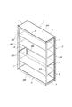
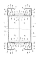
図1に基づいて枠組み構造のラックの全体構成を説明すると、図示のラック1は、最上段棚板2A、最下段棚板2B、及び上下複数段の中間棚板2Cを備えたもので、これら全ての棚板2A〜2Cは、同一構造同一サイズの平面長方形のものである。これら棚板2A〜2Cの周囲を取り囲む枠組み構造体3は、棚板2A〜2Cの四隅に隣接する4本の支柱4A,4B及び5A,5B、これら支柱4A〜5Bの上端部どうし及び下端部どうしを矩形枠状に連結する棚板長さ方向と平行な4本の間口方向連結部材6と棚板幅方向と平行な4本の奥行き方向連結部材7から構成されている。   Referring to FIG. 1, the overall structure of the rack having a frame structure will be described. The illustrated rack 1 includes an uppermost shelf 2A, a lowermost shelf 2B, and intermediate shelf 2C having a plurality of upper and lower stages. All the shelf boards 2A to 2C have a rectangular shape with the same structure and the same size. The frame structure 3 surrounding the periphery of the shelf boards 2A to 2C is composed of four columns 4A, 4B and 5A, 5B adjacent to the four corners of the shelf boards 2A to 2C, and the upper and lower ends of these columns 4A to 5B. It consists of four frontage direction connecting members 6 parallel to the shelf length direction and four depth direction connecting members 7 parallel to the shelf width direction for connecting the two in a rectangular frame shape.

最上段棚板2Aは、支柱4A〜5Bの上端部どうしを連結する前後一対の間口方向連結部材6と左右一対の奥行き方向連結部材7とで形成される矩形枠の内側に配置され、最下段棚板2Bは、支柱4A〜5Bの下端部どうしを連結する前後一対の間口方向連結部材6と左右一対の奥行き方向連結部材7とで形成される矩形枠の内側に配置されている。全ての棚板2A〜2Cは、その長さ方向の両端が、前後一対の支柱4A,5A間と前後一対の支柱4B,5B間に水平に架設された棚受け8によって支持されている。   The uppermost shelf 2A is disposed inside a rectangular frame formed by a pair of front and rear front-end connection members 6 and a pair of left and right depth-direction connection members 7 that connect the upper ends of the columns 4A to 5B. The shelf board 2B is disposed inside a rectangular frame formed by a pair of front-and-rear front-end connection members 6 and a pair of left and right depth-direction connection members 7 that connect lower ends of the columns 4A to 5B. All the shelf plates 2A to 2C are supported at both ends in the length direction by shelf receivers 8 horizontally installed between the pair of front and rear columns 4A and 5A and between the pair of front and rear columns 4B and 5B.

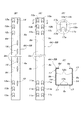
以下、詳細に説明すると、各支柱4A〜5Bは、図2及び図3に示すように、横断面輪郭がほぼ正方形のリップ付きC形鋼から成るもので、背側板部9a、左右一対の横側板部9b,9c、及びリップ板部9d,9eを備え、各支柱4A〜5Bのリップ板部9d,9eがこのラック1の前後奥行き方向で当該ラック1の内側に向かって対面する向きに配置されている。各支柱4A〜5Bの背側板部9aには、その上下両端部に、上下3段の被係合部10a〜10c及び11a〜11cが左右対称に2列設けられている。各支柱4A〜5Bの横側板部9b,9cには、その上下両端部に、上下3段の被係合部12a〜12c及び13a〜13cと、各1つの棚受け係止孔14,15とが設けられている。この上下3段の被係合部12a〜13cは、横側板部9b,9cとリップ板部9d,9eとの間の角部に接近して配設されており、当該角部との間の間隔は、背側板部9aと横側板部9b,9cとの間の角部と上下3段の被係合部10a〜11cとの間の間隔に等しい。棚受け係止孔14,15は、横側板部9b,9cと背側板部9aとの間の角部に接近して配設されており、更に横側板部9b,9cには、これら上下両端の棚受け係止孔14,15の中間において、これら上下両端の棚受け係止孔14,15と同一直線上に並ぶように、同一形状の棚受け係止孔16が等間隔おきに配設されている。   In the following, in detail, as shown in FIGS. 2 and 3, each support column 4A-5B is made of a C-shaped steel with a lip having a substantially square cross-sectional profile. Side plate portions 9b and 9c and lip plate portions 9d and 9e are provided, and the lip plate portions 9d and 9e of the columns 4A to 5B are arranged in a direction facing the inside of the rack 1 in the front-rear depth direction of the rack 1. Has been. The back side plate portion 9a of each support column 4A to 5B is provided with two rows of left and right three-stage engaged portions 10a to 10c and 11a to 11c symmetrically on both upper and lower ends. The lateral side plate portions 9b and 9c of each of the columns 4A to 5B are provided with upper and lower three-stage engaged portions 12a to 12c and 13a to 13c, and one shelf receiving locking holes 14 and 15 at the upper and lower ends, respectively. Is provided. The upper and lower three-stage engaged portions 12a to 13c are arranged close to the corner between the side plates 9b and 9c and the lip plates 9d and 9e, and between the corners. The interval is equal to the interval between the corner between the back plate 9a and the side plates 9b and 9c and the upper and lower engaged portions 10a to 11c. The shelf receiving locking holes 14 and 15 are disposed close to the corners between the side plate portions 9b and 9c and the back plate portion 9a, and the side plate portions 9b and 9c have upper and lower ends. In the middle of the shelf receiving and locking holes 14 and 15, shelf receiving and locking holes 16 having the same shape are arranged at equal intervals so as to be aligned with the shelf receiving and locking holes 14 and 15 at both upper and lower ends. Has been.

全ての被係合部10a〜12cは、図3Aの要部拡大図で示すように、背側板部9a及び横側板部9b,9cを切り抜いて形成された門形切欠開口17によって構成され、中央下辺の上向きの突出板部17a、この突出板部17aの上側のほぼ矩形の上半開口部17b、及び上半開口部17bと連なり且つ突出板部17aの左右両側に位置する脚孔部17c,17dを備えている。又、各被係合部10a〜12cを構成する門形切欠開口17の脚孔部17c,17dの内、横側板部9b,9c又はリップ板部9d,9eに接近している側の脚孔部17cは、その両側縁の内、突出板部17aを形成しない外側の側縁が、下側ほど突出板部17aに接近するように傾斜した相対摺接部18となっている。棚受け係止孔14〜16は、それぞれ同一長さの垂直な縦長スリット状のものである。   All the engaged portions 10a to 12c are constituted by a gate-shaped notch opening 17 formed by cutting out the back side plate portion 9a and the side side plate portions 9b and 9c, as shown in the enlarged view of the main part in FIG. 3A. The lower side upward protruding plate portion 17a, the upper half opening portion 17b of the upper side of the protruding plate portion 17a, and the leg hole portions 17c connected to the upper half opening portion 17b and located on the left and right sides of the protruding plate portion 17a, 17d. Of the leg hole portions 17c and 17d of the gate-shaped notch opening 17 constituting the engaged portions 10a to 12c, the leg holes on the side close to the side plate portions 9b and 9c or the lip plate portions 9d and 9e. The portion 17c is a relative slidable contact portion 18 whose outer side edge that does not form the protruding plate portion 17a is inclined so that the lower side is closer to the protruding plate portion 17a. The shelf receiving engagement holes 14 to 16 are each of a vertically long slit shape having the same length.

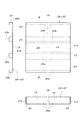
各棚板2A〜2Cは、図4に示すように、長方形の棚板面板19の長さ方向に沿った前後両側辺の下側ほぼ全域にわたって当該棚板面板19の折り曲げにより一体成形された補強用折曲部20a,20bと、当該棚板面板19の長さ方向の両端ほぼ全幅にわたって当該棚板面板19を下向きに90度折曲して一体成形された垂直係止片21a,21bと、棚板面板19の底面に補強用折曲部20a,20bと平行に固着した複数列の補強部材22a,22bを備えている。尚、補強用折曲部20a,20b、垂直係止片21a,21b、及び補強部材22a,22bの高さは同一であり、垂直係止片21a,21bの内側には、補強用折曲部20a,20bの両端と補強部材22a,22bの両端との間に当該垂直係止片21a,21bに沿って連続する所要幅の下側開放の空隙部23が確保されている。   As shown in FIG. 4, each of the shelf boards 2 </ b> A to 2 </ b> C is a reinforcement that is integrally formed by bending the shelf board surface plate 19 over almost the entire lower side of the front and rear sides along the length direction of the rectangular shelf board surface plate 19. Bending portions 20a, 20b for use, and vertical locking pieces 21a, 21b integrally formed by bending the shelf board surface plate 19 downward 90 degrees over substantially the entire width of both ends in the length direction of the shelf board surface plate 19, A plurality of rows of reinforcing members 22a and 22b fixed in parallel to the reinforcing bent portions 20a and 20b are provided on the bottom surface of the shelf plate face plate 19. The reinforcing bent portions 20a and 20b, the vertical locking pieces 21a and 21b, and the reinforcing members 22a and 22b have the same height, and the reinforcing bent portions 21a and 21b are provided inside the reinforcing bent portions. Between the both ends of 20a and 20b and the both ends of the reinforcing members 22a and 22b, a gap 23 having a lower opening and a continuous width along the vertical locking pieces 21a and 21b is secured.

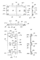
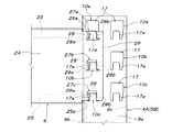
間口方向連結部材6と奥行き方向連結部材7とは、長さが異なるだけで構造は同一であり、図5に示すように、帯状垂直板24の上下両側辺を全長にわたって同一側に角形に折り返して形成した上下両折り返し部25を有すると共に、前記帯状垂直板24の両端を前記上下両折り返し部25の端より所要長さ延出させて形成した接合板部26を長さ方向の両端に有する。これら接合板部26の突出長さは、支柱4A〜5Bの幅の半分以下である。而して、各接合板部26には、上下両折り返し部25の端面25Aを支柱4A〜5Bの横側板部9b,9cに当接させて当該接合板部26を背側板部9aに重ねたとき、或いは上下両折り返し部25の端面25Aを支柱4A〜5Bのリップ板部9d,9eに当接させて当該接合板部26を横側板部9b,9cに重ねたとき、支柱4A〜5Bの背側板部9aに設けられている縦一列で上下3段の被係合部10a〜11c、或いは支柱4A〜5Bの横側板部9b,9cに設けられている縦一列で上下3段の被係合部12a〜13cに合致させることができるように、縦一列で上下3段の係合部27a〜27cが設けられている。   The frontage direction connecting member 6 and the depth direction connecting member 7 have the same structure except for the length, and as shown in FIG. 5, the upper and lower sides of the belt-like vertical plate 24 are folded back to the same side over the entire length. The upper and lower folded portions 25 are formed at the opposite ends of the belt-like vertical plate 24 and the joining plate portions 26 are formed at both ends in the length direction by extending the both ends of the vertical strips 25 from the ends of the upper and lower folded portions 25. . The protruding length of these joining plate portions 26 is less than half of the width of the columns 4A to 5B. Thus, in each joining plate portion 26, the end surfaces 25A of the upper and lower folded portions 25 are brought into contact with the lateral side plate portions 9b and 9c of the columns 4A to 5B, and the joining plate portion 26 is overlapped with the back side plate portion 9a. Or when the end face 25A of the upper and lower folded portions 25 is brought into contact with the lip plate portions 9d and 9e of the support posts 4A to 5B and the joining plate portion 26 is overlapped with the lateral side plate portions 9b and 9c, Engaged portions 10a to 11c in three vertical rows in the vertical row provided on the back side plate portion 9a, or three vertical rows in the vertical row provided in the horizontal side plate portions 9b and 9c of the columns 4A to 5B. The upper and lower three-stage engaging portions 27a to 27c are provided so as to be matched with the joint portions 12a to 13c.

各係合部27a〜27cは、前記接合板部26と一体に連なる左右両横側壁部28a,28bを有する下側辺開放の垂直板部28から構成されている。この垂直板部28は、対応する各被係合部10a〜11cの門形切欠開口17における突出板部17aの上側の上半開口部17bに対して水平に嵌合離脱自在な大きさのほぼ矩形状のもので、前記接合板部26から支柱4A〜5B側に押し出し形成されている。而して、上下3段の係合部27a〜27cの内、中央の係合部27bと最上段の係合部27aの垂直板部28は、接合板部26に設けた水平のスリット29によって下側辺が開放され、最下段の係合部27cの垂直板部28は、その下側辺が接合板部26の下側辺と共通に形成されている。更に、中央の係合部27bと最下段の係合部27cの垂直板部28は、接合板部26と一体に連なり且つ左右両横側壁部28a,28bとも一体に連なる上側壁部28cを備えた、下側辺のみ開放の袋状に構成され、最上段の係合部27aの垂直板部28は、その上側辺が接合板部26の上側辺と共通に形成されて、上側辺も開放されている。   Each engaging part 27a-27c is comprised from the perpendicular | vertical board part 28 of the lower side open | release which has the right-and-left both side wall part 28a, 28b connected to the said joining board part 26 integrally. The vertical plate portion 28 is of a size that can be fitted and removed horizontally with respect to the upper half opening portion 17b above the protruding plate portion 17a in the portal notch opening 17 of each of the corresponding engaged portions 10a to 11c. It has a rectangular shape and is formed by extrusion from the joining plate portion 26 to the support columns 4A to 5B. Thus, among the upper and lower three-stage engaging portions 27a to 27c, the central engaging portion 27b and the vertical plate portion 28 of the uppermost engaging portion 27a are separated by a horizontal slit 29 provided in the joining plate portion 26. The lower side is opened, and the lower side of the vertical plate portion 28 of the lowermost engaging portion 27 c is formed in common with the lower side of the joining plate portion 26. Further, the vertical plate portion 28 of the center engaging portion 27b and the lowermost engaging portion 27c is provided with an upper side wall portion 28c that is continuous with the joining plate portion 26 and that is also continuous with both the left and right side wall portions 28a and 28b. Further, only the lower side is configured as an open bag, and the upper side of the vertical plate 28 of the uppermost engaging portion 27a is formed in common with the upper side of the joining plate 26, and the upper side is also open. Has been.

又、各係合部27a〜27cは、その垂直板部28の左右両側壁部28a,28bの内、接合板部26の基部側、即ち、連結部材6,7の上下両折り返し部25に近い側の側壁部28aは、下方ほど他方の側壁部28bに接近する方向に傾斜しており、その傾斜した外側面が相対摺接部18bを形成している。   Each of the engaging portions 27a to 27c is close to the base side of the joining plate portion 26, that is, the upper and lower folded portions 25 of the connecting members 6 and 7 among the left and right side wall portions 28a and 28b of the vertical plate portion 28. The side wall portion 28a on the side is inclined in a direction closer to the other side wall portion 28b toward the lower side, and the inclined outer surface forms a relative sliding contact portion 18b.

棚受け8は、図2に示すように、帯状垂直板30の両端を直角外向きに折曲して係止片31a,31bを形成すると共に、帯状垂直板30の下側辺を直角内向きに折曲して水平折曲部32を形成したものである。係止片31a,31bは、各支柱4A〜5Bの横側板部9b,9cに設けられた棚受け係止孔14〜16に対して水平に抜き差し自在な大きさで、支柱4A〜5Bの横側板部9b,9cを形成する板材が入り込める幅の切欠き33が下側辺から上向きに形成されている。   As shown in FIG. 2, the shelf receiver 8 is bent at both ends of the belt-like vertical plate 30 outward at a right angle to form locking pieces 31a and 31b, and the lower side of the belt-like vertical plate 30 faces inward at a right angle. The horizontal bent portion 32 is formed by bending the wire. The locking pieces 31a and 31b are sized so as to be horizontally detachable with respect to the shelf receiving locking holes 14 to 16 provided in the lateral side plate portions 9b and 9c of the support columns 4A to 5B. A notch 33 having a width capable of entering a plate material forming the side plate portions 9b and 9c is formed upward from the lower side.

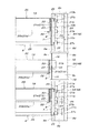
図6〜図10は、上記各部材から組み立てられたラック1における各部材の連結状態を示している。これら図6〜図10に示すように、前後一対の支柱4A,5A及び支柱4B,5Bは、それぞれこれら支柱4A〜5Bの上下両端部において、奥行き方向連結部材7により連結されると共に、前側左右一対の支柱4A,4B及び支柱5A,5Bとは、それぞれこれら支柱4A〜5Bの上下両端部において、間口方向連結部材6より連結される。   6-10 has shown the connection state of each member in the rack 1 assembled from the said each member. As shown in FIGS. 6 to 10, the pair of front and rear columns 4 </ b> A and 5 </ b> A and the columns 4 </ b> B and 5 </ b> B are coupled by the depth direction coupling members 7 at the upper and lower ends of the columns 4 </ b> A to 5 </ b> B. The pair of struts 4A, 4B and the struts 5A, 5B are connected by the frontage direction connecting member 6 at the upper and lower ends of each of the supports 4A-5B.

奥行き方向連結部材7は、その上下両折り返し部25が支柱4A,5Aの内側のリップ板部9d,9e間に位置するように、両端の接合板部26を支柱4A,5Aの内側の横側板部9b,9cに当接させるのであるが、このとき奥行き方向連結部材7の接合板部26に設けられている縦一列で上下3段の係合部27a〜27cを支柱4A〜5Bの横側板部9b,9cの上下両端部に設けられている縦一列で上下3段の被係合部12a〜13cに係合連結させる。一方、間口方向連結部材6は、その上下両折り返し部25が支柱4A,4B及び支柱5A,5Bの内側の横側板部9b,9c間に位置するように、両端の接合板部26を支柱4A,4B及び支柱5A,5Bの背側板部9aに当接させるのであるが、このとき間口方向連結部材6の接合板部26に設けられている縦一列で上下3段の係合部27a〜27cを支柱4A〜5Bの横側板部9b,9cの上下両端部に設けられている縦一列で上下3段の被係合部10a〜11cに係合連結させる。   In the depth direction connecting member 7, the upper and lower folded portions 25 are positioned between the lip plate portions 9d and 9e inside the columns 4A and 5A, and the joining plate portions 26 at both ends are connected to the side plates inside the columns 4A and 5A. At this time, the upper and lower three-stage engaging portions 27a to 27c provided in the joining plate portion 26 of the depth direction connecting member 7 are arranged on the side plates of the columns 4A to 5B. The upper and lower ends of the portions 9b and 9c are engaged and connected to the engaged portions 12a to 13c of the upper and lower three stages in a single vertical row. On the other hand, the front end direction connecting member 6 has the upper and lower folded portions 25 positioned between the side plates 9b and 9c inside the columns 4A and 4B and the columns 5A and 5B. , 4B and the back side plate portion 9a of the support columns 5A, 5B. At this time, the upper and lower three-stage engaging portions 27a-27c provided in the joining plate portion 26 of the frontage direction connecting member 6 are arranged. Are engaged and connected to the engaged portions 10a to 11c of the upper and lower three stages in a single vertical row provided at the upper and lower end portions of the lateral side plate portions 9b and 9c of the columns 4A to 5B.

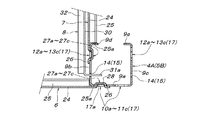
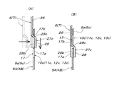
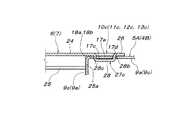
上記の各連結部材6,7の接合板部26における係合部27a〜27cを支柱4A〜5B側の被係合部12a〜13c又は被係合部10a〜11cに係合連結させる方法を具体的に説明すると、図13A及び図14Aに示すように、各係合部27a〜27cの内側に突出している垂直板部28を各被係合部10a〜13cの門形切欠開口17における突出板部17aの上側の上半開口部17bに嵌合させる。この状態で連結部材6,7(接合板部26)を支柱4A〜5Bに沿って押し下げると、各垂直板部28の開放されている下辺から当該垂直板部28の内側、即ち、左右一対の横側壁部28a,28bと垂直板部28とで囲まれた偏平な上下方向の凹入空間内に被係合部10a〜13cの突出板部17aが相対的に挿入される。この垂直板部28の内側凹入空間内へ突出板部17aが相対的に挿入される行程において、横側壁部28a,28bが被係合部10a〜13cの突出板部17aの両側の脚孔部17c,17d内に下向きに挿入されるが、このとき、片側の横側壁部28aの相対摺接部(傾斜している外側面)18bが脚孔部17cの傾斜した相対摺接部18aに摺接することにより、連結部材6,7と支柱4A〜5Bとが、連結部材6,7の長さ方向で互いに接近移動することになる。   Specifically, a method of engaging and connecting the engaging portions 27a to 27c in the joining plate portion 26 of each of the connecting members 6 and 7 to the engaged portions 12a to 13c or the engaged portions 10a to 11c on the column 4A to 5B side. Specifically, as shown in FIGS. 13A and 14A, the vertical plate 28 protruding inside the engaging portions 27a to 27c is replaced with a protruding plate in the gate-shaped notch opening 17 of the engaged portions 10a to 13c. The upper half opening 17b on the upper side of the portion 17a is fitted. In this state, when the connecting members 6 and 7 (joining plate portion 26) are pushed down along the columns 4A to 5B, the inner side of the vertical plate portion 28, that is, a pair of left and right from the open lower side of each vertical plate portion 28. The protruding plate portions 17a of the engaged portions 10a to 13c are relatively inserted into a flat vertical recessed space surrounded by the lateral side wall portions 28a and 28b and the vertical plate portion 28. In the process of relatively inserting the protruding plate portion 17a into the inner recessed space of the vertical plate portion 28, the lateral side wall portions 28a and 28b are leg holes on both sides of the protruding plate portion 17a of the engaged portions 10a to 13c. At this time, the relative sliding contact portion (inclined outer surface) 18b of the lateral side wall portion 28a on one side is inserted into the inclined relative sliding contact portion 18a of the leg hole portion 17c. By slidably contacting, the connecting members 6, 7 and the columns 4 </ b> A to 5 </ b> B move closer to each other in the length direction of the connecting members 6, 7.

従って、図13B、図14B、及び図15に示すように、連結部材6,7(接合板部26)が支柱4A〜5Bに沿って下降限位置まで降下したとき、即ち、係合部27a〜27cの左右一対の横側壁部28a,28bの下端が被係合部10a〜13cの左右一対の脚孔部17c,17dの下端付近まで降下したとき、前記相対摺接部18a,18bによる、連結部材6,7と支柱4A〜5Bとの連結部材6,7の長さ方向の接近移動量が最大になり、間口方向連結部材6の上下両折り返し部25の端面25aが支柱4A〜5Bの横側板部9b,9cに当接又は近接し、奥行き方向連結部材7の上下両折り返し部25の端面25aが支柱4A〜5Bのリップ板部9d,9eに当接又は近接することになる。勿論、連結部材6,7(接合板部26)が支柱4A〜5Bに沿って下降限位置まで降下したとき、係合部27a〜27cの左右一対の横側壁部28a,28bの内、傾斜していない横側壁部28bの内外両側面は、被係合部10a〜13cの脚孔部17dにおける内外両側面(内側は突出板部17aの側縁)から離れており、当該横側壁部28bの水平方向の位置は被係合部10a〜13cの脚孔部17dによって拘束されていない。   Therefore, as shown in FIG. 13B, FIG. 14B, and FIG. 15, when the connecting members 6 and 7 (joining plate portion 26) are lowered to the lower limit position along the columns 4A to 5B, that is, the engaging portions 27a to 27a. When the lower ends of the pair of left and right lateral wall portions 28a and 28b of 27c are lowered to the vicinity of the lower ends of the pair of left and right leg hole portions 17c and 17d of the engaged portions 10a to 13c, they are connected by the relative sliding contact portions 18a and 18b. The amount of movement in the length direction of the connecting members 6, 7 between the members 6, 7 and the columns 4 </ b> A to 5 </ b> B is maximized, and the end surface 25 a of the upper and lower folded portions 25 of the frontage direction connecting member 6 is The side plates 9b and 9c are in contact with or close to each other, and the end surfaces 25a of the upper and lower folded portions 25 of the depth direction connecting member 7 are in contact with or close to the lip plates 9d and 9e of the columns 4A to 5B. Of course, when the connecting members 6 and 7 (joining plate portion 26) are lowered to the lower limit position along the support posts 4A to 5B, the pair of left and right side wall portions 28a and 28b of the engaging portions 27a to 27c are inclined. Both the inner and outer side surfaces of the lateral side wall portion 28b that is not separated from the inner and outer side surfaces (inside is the side edges of the protruding plate portion 17a) of the leg hole portions 17d of the engaged portions 10a to 13c. The position in the horizontal direction is not constrained by the leg hole portion 17d of the engaged portions 10a to 13c.

又、上記のようにして各連結部材6,7の接合板部26を支柱4A〜5Bの上下両端部に係合連結させたとき、接合板部26が支柱4A〜5Bの背側板部9a又は横側板部9b,9cから離れる方向に水平移動することは、支柱4A〜5B側の被係合部10a〜13cの突出板部17aと接合板部26側の係合部27a〜27cの垂直板部28とが互いに当接して阻止しており、接合板部26が支柱4A〜5Bの背側板部9a又は横側板部9b,9cに当接する状態に保持される。このとき、支柱4A〜5Bの横側板部9b,9c又はリップ板部9d,9eに当接又は近接する各連結部材6,7の上下両折り返し部25の端面25aの内、最下位部(下側折り返し部25の水平部の端面)は、図14に示すように、最下段の係合部27cと最下段の被係合部10c(11c,12c,13c)とが互いに嵌合する位置より若干低くなるように構成されている。又、図10に示すように、各連結部材6,7の上下両折り返し部25の端面25aの内、最上位部(上側折り返し部25の水平部の端面)は、最上段の係合部27aと最上段の被係合部10a(11a,12a,13a)とが互いに嵌合する位置より若干高くなるように構成されている。   Further, when the joining plate portions 26 of the connecting members 6 and 7 are engaged and connected to the upper and lower ends of the support posts 4A to 5B as described above, the joining plate portion 26 is connected to the back side plate portion 9a of the support posts 4A to 5B or The horizontal movement in the direction away from the lateral side plate portions 9b and 9c means that the vertical plates of the protruding plate portions 17a of the engaged portions 10a to 13c on the columns 4A to 5B side and the engaging portions 27a to 27c on the joining plate portion 26 side. The part 28 is in contact with each other to prevent it, and the joining plate part 26 is held in a state of contacting the back side plate part 9a or the side side plate parts 9b, 9c of the columns 4A to 5B. At this time, among the end surfaces 25a of the upper and lower folded portions 25 of the connecting members 6, 7 that are in contact with or close to the lateral side plate portions 9b, 9c or the lip plate portions 9d, 9e of the columns 4A-5B, As shown in FIG. 14, the end surface of the horizontal portion of the side folded portion 25 is located at a position where the lowermost engaging portion 27c and the lowermost engaged portion 10c (11c, 12c, 13c) are fitted to each other. It is configured to be slightly lower. As shown in FIG. 10, the uppermost portion (the end surface of the horizontal portion of the upper folded portion 25) of the end surfaces 25a of the upper and lower folded portions 25 of the connecting members 6 and 7 is the uppermost engaging portion 27a. And the uppermost engaged portion 10a (11a, 12a, 13a) are configured to be slightly higher than the positions where they are fitted to each other.

上記のように、各支柱4A〜5Bの上下両端部を前後一対の間口方向連結部材6と左右一対の奥行き方向連結部材7とで平面矩形状に連結一体化することにより、枠組み構造体3が構成されるが、この枠組み構造体3の上端側に左右間口方向の水平外力が作用して、枠組み構造体3が左右水平方向に平行四辺形状に変形しようとしたとき、各間口方向連結部材6が支柱4A〜5Bに対して相対的に垂直上下方向に傾動しようとすることになる。このとき、各間口方向連結部材6の端部で支柱4A〜5Bに対して下方へ相対的に傾動することになる端部では、間口方向連結部材6の下側の折り返し部25の端面25aの最下位部と支柱4A〜5Bの横側板部9b,9cとの当接部を支点にして間口方向連結部材6が支柱4A〜5Bに対して下方へ相対的に傾動することになるので、当該端面25aの最下位部より上方にある縦一列上下3段の被係合部10a〜13cと係合部27a〜27cとの全ての連結部が、当該間口方向連結部材6の支柱4A〜5Bに対する下方への傾動を抑止することになる。又、各間口方向連結部材6の端部で支柱4A〜5Bに対して上方へ相対的に傾動することになる端部では、間口方向連結部材6の上側の折り返し部25の端面25aの最上位部と支柱4A〜5Bの横側板部9b,9cとの当接部を支点にして間口方向連結部材6が支柱4A〜5Bに対して上方へ相対的に傾動することになるので、当該端面25aの最上位部より下方にある縦一列上下3段の被係合部10a〜13cと係合部27a〜27cとの全ての連結部が、当該間口方向連結部材6の支柱4A〜5Bに対する上方への傾動を抑止することになる。   As described above, the upper and lower ends of each of the columns 4A to 5B are connected and integrated in a planar rectangular shape by the pair of front and rear front end direction connecting members 6 and the pair of left and right depth direction connecting members 7, whereby the frame structure 3 is formed. However, when a horizontal external force in the left-right front direction acts on the upper end side of the frame structure 3 and the frame structure 3 tries to deform into a parallelogram in the left-right horizontal direction, each front-direction connecting member 6 is configured. Tends to tilt in the vertical vertical direction relative to the columns 4A to 5B. At this time, at the end portion of each frontage direction connecting member 6 that tilts downward relative to the columns 4A to 5B, the end surface 25a of the lower folded portion 25 on the lower side of the frontage direction connecting member 6 Since the front-end direction connecting member 6 tilts relatively downward with respect to the columns 4A to 5B with the contact portion between the lowest part and the side plates 9b and 9c of the columns 4A to 5B as fulcrums, All the connecting parts of the engaged parts 10a to 13c and the engaging parts 27a to 27c in the three vertical rows above and below the lowest part of the end face 25a are connected to the columns 4A to 5B of the front-side connecting member 6 The downward tilt will be suppressed. Moreover, in the edge part which will incline relatively upward with respect to support | pillar 4A-5B in the edge part of each frontage direction connection member 6, the uppermost end surface 25a of the folding | returning part 25 above the frontage direction connection member 6 is provided. Since the front end direction connecting member 6 is tilted relatively upward with respect to the columns 4A to 5B with the contact portion between the column and the side plates 9b and 9c of the columns 4A to 5B as fulcrums, the end surface 25a All of the connecting portions of the engaged portions 10a to 13c and the engaging portions 27a to 27c of the upper and lower three rows in the vertical line below the uppermost portion of the front are connected to the columns 4A to 5B of the frontage direction connecting member 6 upward. Will be prevented from tilting.

同様に、枠組み構造体3の上端側に前後奥行き方向の水平外力が作用して、枠組み構造体3が前後水平方向に平行四辺形状に変形しようとしたとき、各奥行き方向連結部材7が支柱4A〜5Bに対して相対的に垂直上下方向に傾動しようとすることになる。このとき、各奥行き方向連結部材7の端部で支柱4A〜5Bに対して下方へ相対的に傾動することになる端部では、奥行き方向連結部材7の下側の折り返し部25の端面25aの最下位部と支柱4A〜5Bのリップ板部9d,9eとの当接部を支点にして奥行き方向連結部材7が支柱4A〜5Bに対して下方へ相対的に傾動することになるので、当該端面25aの最下位部より上方にある縦一列上下3段の被係合部10a〜13cと係合部27a〜27cとの全ての連結部が、当該奥行き方向連結部材7の支柱4A〜5Bに対する下方への傾動を抑止することになる。又、各奥行き方向連結部材7の端部で支柱4A〜5Bに対して上方へ相対的に傾動することになる端部では、奥行き方向連結部材7の上側の折り返し部25の端面25aの最上位部と支柱4A〜5Bのリップ板部9d,9eとの当接部を支点にして奥行き方向連結部材7が支柱4A〜5Bに対して上方へ相対的に傾動することになるので、当該端面25aの最上位部より下方にある縦一列上下3段の被係合部10a〜13cと係合部27a〜27cとの全ての連結部が、当該奥行き方向連結部材7の支柱4A〜5Bに対する上方への傾動を抑止することになる。   Similarly, when a horizontal external force in the front-rear depth direction acts on the upper end side of the frame structure 3 and the frame structure 3 tries to deform into a parallelogram shape in the front-rear horizontal direction, each depth-direction connecting member 7 is connected to the column 4A. It will try to tilt in the vertical vertical direction relative to ˜5B. At this time, at the end portion of each depth direction connecting member 7 that tilts downward relative to the columns 4 </ b> A to 5 </ b> B, the end surface 25 a of the folded portion 25 on the lower side of the depth direction connecting member 7. Since the depth direction connecting member 7 is tilted relatively downward with respect to the columns 4A to 5B with the contact portion between the lowest part and the lip plate portions 9d and 9e of the columns 4A to 5B as fulcrums, All the connecting portions of the engaged portions 10a to 13c and the engaging portions 27a to 27c in the three vertical rows above and below the lowest portion of the end surface 25a are connected to the columns 4A to 5B of the depth direction connecting member 7. The downward tilt will be suppressed. Further, at the end portion of each depth direction connecting member 7 that tilts relatively upward with respect to the columns 4A to 5B, the uppermost end surface 25a of the folded portion 25 on the upper side of the depth direction connecting member 7 is provided. Since the depth-direction connecting member 7 is tilted relatively upward with respect to the support columns 4A to 5B with the contact portion between the support portion and the lip plate portions 9d and 9e of the support columns 4A to 5B as a fulcrum, the end surface 25a All of the connecting parts of the engaged parts 10a to 13c and the engaging parts 27a to 27c of the upper and lower three stages in the vertical row below the uppermost part of the upper part of the depth direction connecting member 7 with respect to the columns 4A to 5B Will be prevented from tilting.

尚、図示省略しているが、従来周知のように、上記のように枠組み構造体3を組み立てた状態において、間口方向連結部材6及び奥行き方向連結部材7の接合板部26と各支柱4A〜5Bの背側板部9a又は横側板部9b,9cとを、両者に設けられた貫通孔に係止ピンを着脱自在に挿通して、接合板部26が支柱4A〜5Bに対して上動するのを阻止できるように構成することができる。又、支柱4A〜5Bの上下両端部に矩形枠状に連結された間口方向連結部材6及び奥行き方向連結部材7は、それぞれ同一レベルに位置している。   Although not shown in the drawings, as is conventionally known, in the state where the frame structure 3 is assembled as described above, the joint plate portions 26 of the frontage direction connecting member 6 and the depth direction connecting member 7 and the respective columns 4A to 4A. A locking pin is detachably inserted through the back side plate portion 9a or the side plate portions 9b and 9c of 5B through the through holes provided in both, and the joining plate portion 26 moves upward with respect to the columns 4A to 5B. It can be configured to prevent this. Moreover, the frontage direction connecting member 6 and the depth direction connecting member 7 connected to the upper and lower ends of the columns 4A to 5B in a rectangular frame shape are positioned at the same level.

組み立てられた枠組み構造体3には、図7及び図9に示すように、棚受け8が取り付けられる。この棚受け8は、前後対を成す支柱4A,5A間及び支柱4B,5B間に、左右2つの棚受け8が同一レベルになるように、適宜取付け高さを選択して取り付けられるが、ラック1の天板に相当する最上段棚板2Aを支持する棚受け8は、支柱上端部に架設されている奥行き方向連結部材7の内側定位置に取り付けられ、ラック1の底板に相当する最下段棚板2Bを支持する棚受け8は、支柱下端部に架設されている奥行き方向連結部材7の内側定位置に取り付けられる。   As shown in FIGS. 7 and 9, a shelf holder 8 is attached to the assembled frame structure 3. The shelf holder 8 is attached by selecting an appropriate mounting height so that the two left and right shelf holders 8 are at the same level between the support posts 4A and 5A and the support posts 4B and 5B forming the front and rear pairs. A shelf receiver 8 that supports an uppermost shelf 2 </ b> A corresponding to one top plate is attached to a fixed position on the inner side of the depth-direction connecting member 7 that is installed on the upper end of the column, and is a lowermost step corresponding to the bottom plate of the rack 1. The shelf support 8 that supports the shelf 2B is attached to a fixed position on the inner side of the depth direction connecting member 7 that is installed at the lower end of the column.

即ち、図9及び図11に示すように、各奥行き方向連結部材7の内側に配置した棚受け8の両端の係止片31a,31bを、前後対を成す支柱4A,5A及び支柱4B,5Bの横側板部9b,9cの上下両端部に設けられている棚受け係止孔14,15に差し込んで降下させ、各係止片31a,31bの切欠き33を、棚受け係止孔14,15の下端に嵌合させる。このようにして各奥行き方向連結部材7の内側に配置した棚受け8を、前後対を成す支柱4A,5A間及び支柱4B,5B間に架設したとき、当該奥行き方向連結部材7の帯状垂直板24と棚受け8の帯状垂直板30との間に、図9に示すように空隙が確保されるので、この空隙内に最上段棚板2A及び最下段棚板2Bの垂直係止片21a,21bを図11に示すように上から差し込むようにして、最上段棚板2A及び最下段棚板2Bの棚板面板19の長さ方向両端を棚受け8の帯状垂直板30の上辺に支持させる。このとき、棚受け8の帯状垂直板30は、最上段棚板2A及び最下段棚板2Bの垂直係止片21a,21bの内側の空隙部23に入り込むと共に、当該垂直係止片21a,21bの両端部は、棚受け8の帯状垂直板30の両端部と前後対を成す支柱4A,5A及び支柱4B,5Bの横側板部9b,9cとの間の空隙部内に入り込んでいる。このようにして支持された最上段棚板2A及び最下段棚板2Bは、その周囲を間口方向連結部材6と奥行き方向連結部材7とで取り囲まれており、その棚板面板19は、間口方向連結部材6の上側辺及び奥行き方向連結部材7の上側辺とほぼ同一レベルに位置している。   That is, as shown in FIGS. 9 and 11, the locking pieces 31 a and 31 b at both ends of the shelf receiver 8 arranged inside each depth direction connecting member 7 are connected to the support posts 4A and 5A and the support posts 4B and 5B. The side plate portions 9b and 9c are inserted into shelf receiving holes 14 and 15 provided at both upper and lower ends and lowered so that the notches 33 of the engaging pieces 31a and 31b are inserted into the shelf receiving engaging holes 14 and 15 respectively. 15 is fitted to the lower end. In this way, when the shelf holders 8 arranged inside the depth direction connecting members 7 are installed between the support columns 4A and 5A and the support columns 4B and 5B forming the front and rear pairs, the vertical strips of the depth direction connection members 7 are provided. 24 and a belt-like vertical plate 30 of the shelf support 8, a gap is secured as shown in FIG. 9, so that the vertical locking pieces 21 a of the uppermost shelf 2 </ b> A and the lowermost shelf 2 </ b> B are placed in this gap. 11b is inserted from above as shown in FIG. 11, and both ends in the length direction of the shelf surface plate 19 of the uppermost shelf 2A and the lowermost shelf 2B are supported on the upper side of the belt-like vertical plate 30 of the shelf support 8. . At this time, the belt-like vertical plate 30 of the shelf receiver 8 enters the gap 23 inside the vertical locking pieces 21a and 21b of the uppermost shelf 2A and the lowermost shelf 2B, and the vertical locking pieces 21a and 21b. The both end portions of the stake are inserted into the space between the both end portions of the strip-shaped vertical plate 30 of the shelf support 8 and the support plate 4A, 5A and the side plate portions 9b, 9c of the support posts 4B, 5B. The uppermost shelf 2 </ b> A and the lowermost shelf 2 </ b> B supported in this manner are surrounded by the frontage direction connecting member 6 and the depth direction connecting member 7, and the shelf board face plate 19 is arranged in the frontage direction. The upper side of the connecting member 6 and the upper side of the depth direction connecting member 7 are located at substantially the same level.

中間棚板2Cを支持する棚受け8は、図12に示すように、前後対を成す支柱4A,5A間及び支柱4B,5B間に、各支柱4A〜5Bの横側板部9b,9cに設けられている中間高さの棚受け係止孔16を利用して上記の要領で架設し、この棚受け8の帯状垂直板30に中間棚板2Cの垂直係止片21a,21bを引っ掛けるようにして、中間棚板2Cの棚板面板19の長さ方向両端を棚受け8の帯状垂直板30の上辺に支持させれば良い。このとき、中間棚板2Cの垂直係止片21a,21bの両端部は、棚受け8の帯状垂直板30の両端部と前後対を成す支柱4A,5A及び支柱4B,5Bの横側板部9b,9cとの間の空隙部内に入り込んでいる。   As shown in FIG. 12, the shelf receiver 8 that supports the intermediate shelf 2C is provided on the side plates 9b and 9c of the columns 4A to 5B between the columns 4A and 5A and between the columns 4B and 5B forming the front and rear pairs. It is constructed in the above-described manner using the shelf receiving hole 16 of the intermediate height, and the vertical engaging pieces 21a and 21b of the intermediate shelf 2C are hooked on the belt-like vertical plate 30 of the shelf receiver 8. Thus, both ends in the length direction of the shelf plate surface plate 19 of the intermediate shelf plate 2 </ b> C may be supported on the upper side of the belt-like vertical plate 30 of the shelf receiver 8. At this time, both end portions of the vertical locking pieces 21a and 21b of the intermediate shelf 2C are the side plates 9b of the columns 4A and 5A and the columns 4B and 5B that form front and rear pairs with both ends of the belt-like vertical plate 30 of the shelf holder 8. , 9c.

尚、相対摺接部18a,18bは、本発明に必須のものではないので、無くすこともできる。又、被係合部及び係合部として、縦一列上下3段の被係合部10a〜13cと係合部27a〜27cを設けたが、上下方向の段数は限定されない(一段でも良い)。又、間口方向連結部材6と奥行き方向連結部材7の両方に、本発明による被係合部10a〜13cと係合部27a〜27cを設けたが、何れか一方の連結部材にのみ本発明の構成を適用しても良い。更に、接合板部26に係合部27a〜27cを上下複数段(4段又はそれ以上でも良い)に配設する場合、最下段の係合部27cの垂直板部28の開放下側辺を接合板部26の下側辺と共通にしないで、接合板部26の下側辺より上方に離して最下段の係合部27cを設けることもできるし、最上段の係合部27aを最下段の係合部27c又は中段の係合部27bと同一構造にし、その垂直板部28の上側壁部28cを接合板部26の上側辺より下方に下げて、接合板部26の上側辺より下方に離して最上段の係合部27aを設けることもできる。勿論、最下段の係合部27cや中段の係合部27bも、最上段の係合部27aと同様に、その垂直板部28の上下両側辺が開放された構造とすることができる。   The relative sliding contact portions 18a and 18b are not essential for the present invention and can be eliminated. Further, although the engaged portions 10a to 13c and the engaging portions 27a to 27c are provided as the engaged portion and the engaging portion in three vertical rows, the number of vertical steps is not limited (a single step may be used). Further, the engaged portions 10a to 13c and the engaging portions 27a to 27c according to the present invention are provided in both the frontage direction connecting member 6 and the depth direction connecting member 7, but only one of the connecting members of the present invention is provided. A configuration may be applied. Furthermore, when the engaging portions 27a to 27c are arranged in a plurality of upper and lower stages (four or more stages) on the joining plate portion 26, the lower open side of the vertical plate portion 28 of the lowermost engaging portion 27c is defined. The lowermost engaging portion 27c can be provided apart from the lower side of the bonding plate portion 26 without being shared with the lower side of the bonding plate portion 26, or the uppermost engaging portion 27a can be provided at the uppermost position. The same structure as the lower engaging portion 27c or the middle engaging portion 27b is used, and the upper side wall portion 28c of the vertical plate portion 28 is lowered below the upper side of the joining plate portion 26 so It is also possible to provide the uppermost engaging portion 27a separated downward. Of course, the lowermost engaging portion 27c and the middle engaging portion 27b can also have a structure in which the upper and lower sides of the vertical plate portion 28 are opened in the same manner as the uppermost engaging portion 27a.

又、従来周知のように、連結部材6,7の端から延出する接合板部26の上下幅を連結部材6,7の上下幅より大きくしても良い。この場合、接合板部26の上下幅に余裕があるから、中段の係合部27bと同一構造(垂直板部28が下側辺のみ開放の袋状構造)の係合部を、接合板部26の上下両側辺から内側に離した状態で上下複数段に設けることが容易である。   Further, as is conventionally known, the vertical width of the joining plate portion 26 extending from the ends of the connecting members 6 and 7 may be larger than the vertical width of the connecting members 6 and 7. In this case, since there is a margin in the vertical width of the joining plate portion 26, the engaging portion having the same structure as the middle engaging portion 27 b (the vertical plate portion 28 is a bag-like structure in which only the lower side is open) is used as the joining plate portion. It is easy to provide a plurality of upper and lower stages in a state separated from both upper and lower sides of the inner side.

本発明のラックの枠組み構造は、支柱と支柱間の連結部材とで構成された枠組みに棚板を支持させて構成される各種の物品収納ラックに活用できる。   The rack frame structure of the present invention can be used for various article storage racks that are configured by supporting a shelf board on a frame composed of columns and connecting members between columns.

1 ラック
2A 最上段棚板
2B 最下段棚板
2C 中間棚板
3 枠組み構造体
4A〜5B 支柱
6 間口方向連結部材
7 奥行き方向連結部材
8 棚受け
9a 支柱の背側板部
9b,9c 支柱の横側板部
9d,9e 支柱のリップ板部
10a〜13c 被係合部
14〜16 棚受け係止孔
17 門形切欠開口
17a 門形切欠開口の突出板部
17b 門形切欠開口の上半開口部
17c,17d 門形切欠開口の脚孔部
18a 被係合部の相対摺接部
18b 係合部の相対摺接部
21a,21b 棚板の垂直係止片
23 空隙部
25 連結部材の上下両折り返し部
25a 上下両折り返し部の端面
26 連結部材の接合板部
27a〜27c 係合部
28 係合部の垂直板部
28a,28b 係合部の横側壁部
28c 係合部の上側壁部
30 棚受けの帯状垂直板
31a,31b 棚受けの係止片
32 水平折曲部
33 係止片の切欠き
DESCRIPTION OF SYMBOLS 1 Rack 2A Top shelf board 2B Bottom shelf board 2C Intermediate shelf board 3 Frame structure 4A-5B Post 6 Frontage direction connection member 7 Depth direction connection member 8 Shelf support 9a Back side plate part of support 9b, 9c Post side plate Parts 9d, 9e lip plate parts 10a-13c engaged parts 14-16 shelf receiving locking holes 17 gate-shaped notch openings 17a projecting plate parts of the portal-shaped notch openings 17b upper half openings 17c of the gate-shaped notch openings, 17d Leg hole portion of the gate-shaped notch opening 18a Relative sliding contact portion of the engaged portion 18b Relative sliding contact portion of the engaging portion 21a, 21b Vertical locking piece of the shelf plate 23 Cavity portion 25 Upper and lower both folded portions 25a of the connecting member End surfaces of the upper and lower folded portions 26 Joining plate portions 27a to 27c of the connecting members Engaging portions 28 Vertical plate portions 28a and 28b of the engaging portions Horizontal side wall portions 28c of the engaging portions Upper side wall portions 30 of the engaging portions 30 Vertical plate 1a, notches of the locking piece 32 horizontally bent portion 33 engaging piece of 31b shelf support

Claims (3)

支柱どうしを連結する連結部材の端から当該連結部材の延長方向に突出して支柱の側面に当接する接合板部に係合部が設けられ、支柱の前記側面には、前記係合部が下向きに係合する連結部材支持用被係合部が設けられたラックの枠組み構造において、前記被係合部は、支柱の側面に設けられ且つ下辺から上向きの突出板部を備えた門形切欠開口で構成され、前記係合部は、前記被係合部の門形切欠開口に前記突出板部の上側で嵌合可能に前記接合板部から支柱側に押し出し形成されたもので、当該接合板部と一体に連なる左右両側壁部を有する下側辺開放の垂直板部を備え、この係合部を前記被係合部の門形切欠開口に嵌合させた状態で前記接合板部を下向きに移動させたとき、前記被係合部の突出板部が当該係合部の左右両側壁部間で垂直板部の外側に入り込むように構成された、ラックの枠組み構造。   An engaging portion is provided on a joining plate portion that protrudes in an extending direction of the connecting member from the end of the connecting member that connects the columns to each other and contacts the side surface of the column, and the engaging portion faces downward on the side surface of the column. In the frame structure of the rack provided with the engaged portion for supporting the connecting member to be engaged, the engaged portion is a gate-shaped notch opening provided on the side surface of the column and provided with a protruding plate portion upward from the lower side. The engaging portion is formed by extruding the connecting plate portion from the connecting plate portion to the support column side so as to be fitted to the gate-shaped notch opening of the engaged portion on the upper side of the protruding plate portion. A vertical plate portion having a lower side opening that has both left and right side wall portions that are integrally connected to each other, and the joint plate portion faces downward in a state where the engagement portion is fitted to the gate-shaped notch opening of the engaged portion. When moved, the protruding plate portion of the engaged portion is suspended between the left and right side wall portions of the engaging portion. Configured so as to enter the outside of the plate portion, the rack of the framework. 前記係合部の垂直板部は、左右両側辺と上側辺とが接合板部と一体に連なって下側辺のみ開放の袋状に形成されている、請求項1に記載のラックの枠組み構造。   The rack frame structure according to claim 1, wherein the vertical plate portion of the engaging portion is formed in a bag shape in which both the left and right sides and the upper side are integrally connected to the joining plate portion and only the lower side is open. . 前記係合部の垂直板部は、左右両側辺のみが前記両側壁部で接合板部と一体に連なって上下両側辺が開放されている、請求項1に記載のラックの枠組み構造。   2. The rack frame structure according to claim 1, wherein the vertical plate portion of the engaging portion has only the left and right sides thereof integrally connected to the joining plate portion at the both side walls and the upper and lower sides are open.
JP2009148539A 2009-06-23 2009-06-23 Rack frame structure Active JP5168666B2 (en)

Priority Applications (1)

Application Number Priority Date Filing Date Title
JP2009148539A JP5168666B2 (en) 2009-06-23 2009-06-23 Rack frame structure

Applications Claiming Priority (1)

Application Number Priority Date Filing Date Title
JP2009148539A JP5168666B2 (en) 2009-06-23 2009-06-23 Rack frame structure

Publications (2)

Publication Number Publication Date
JP2011004792A true JP2011004792A (en) 2011-01-13
JP5168666B2 JP5168666B2 (en) 2013-03-21

Family

ID=43562198

Family Applications (1)

Application Number Title Priority Date Filing Date
JP2009148539A Active JP5168666B2 (en) 2009-06-23 2009-06-23 Rack frame structure

Country Status (1)

Country Link
JP (1) JP5168666B2 (en)

Citations (5)

* Cited by examiner, † Cited by third party
Publication number Priority date Publication date Assignee Title
JPS49128521U (en) * 1973-03-02 1974-11-05
JPS5880039U (en) * 1981-11-26 1983-05-30 株式会社伊藤喜工作所 Attachment device for top plate or bottom plate in assembled shelves
JPS58182005U (en) * 1982-05-31 1983-12-05 株式会社伊藤喜工作所 Strut joint device
JPH0657244U (en) * 1991-05-27 1994-08-09 株式会社岡村製作所 Rod mounting device to the column
JP2006014790A (en) * 2004-06-30 2006-01-19 Meiko Kogyo Kk Self-assembly shelf

Patent Citations (5)

* Cited by examiner, † Cited by third party
Publication number Priority date Publication date Assignee Title
JPS49128521U (en) * 1973-03-02 1974-11-05
JPS5880039U (en) * 1981-11-26 1983-05-30 株式会社伊藤喜工作所 Attachment device for top plate or bottom plate in assembled shelves
JPS58182005U (en) * 1982-05-31 1983-12-05 株式会社伊藤喜工作所 Strut joint device
JPH0657244U (en) * 1991-05-27 1994-08-09 株式会社岡村製作所 Rod mounting device to the column
JP2006014790A (en) * 2004-06-30 2006-01-19 Meiko Kogyo Kk Self-assembly shelf

Also Published As

Publication number Publication date
JP5168666B2 (en) 2013-03-21

Similar Documents

Publication Publication Date Title
RU2004112561A (en) RACK SYSTEM FOR STORAGE AND ARCHIVING OF ITEMS
KR20100137586A (en) Assembling shelf
CN105849424B (en) Assembly type block is constructed and latch-release part
KR20180131781A (en) Angle shelf frame
KR20190089786A (en) Assembly type for shelf
JP2009195677A (en) Merchandise display rack including at least one vertical post and primary support member suitable for the vertical post
JP5168667B2 (en) Rack frame structure
JP5168666B2 (en) Rack frame structure
KR200391947Y1 (en) Structure of sectional display stand
JP5360395B2 (en) Rack shelf support structure
JP5360394B2 (en) Rack frame structure
JPH10165233A (en) Shelf member linking structure for sectional shelf
JP2006014791A (en) Shelf plate attaching structure in self-assembly shelf
JP3980981B2 (en) Nested and connected racks
JP2006014790A (en) Self-assembly shelf
JP3238859B2 (en) Display device and connection structure thereof
JP4388508B2 (en) Storage rack
JP3419716B2 (en) Connection structure between columns and cross beams on shelves
JP5144343B2 (en) Shelf equipment
JP2001187610A (en) Movable shelf
CN220949244U (en) Detachable handle structure
CN211048761U (en) Layer frame device
JP4418067B2 (en) Panel mounting structure for shelf equipment
JP3117388U (en) Spacer block
JP5590469B2 (en) rack

Legal Events

Date Code Title Description
A621 Written request for application examination

Free format text: JAPANESE INTERMEDIATE CODE: A621

Effective date: 20110331

TRDD Decision of grant or rejection written
A01 Written decision to grant a patent or to grant a registration (utility model)

Free format text: JAPANESE INTERMEDIATE CODE: A01

Effective date: 20121130

A61 First payment of annual fees (during grant procedure)

Free format text: JAPANESE INTERMEDIATE CODE: A61

Effective date: 20121213

R150 Certificate of patent or registration of utility model

Ref document number: 5168666

Country of ref document: JP

Free format text: JAPANESE INTERMEDIATE CODE: R150

R250 Receipt of annual fees

Free format text: JAPANESE INTERMEDIATE CODE: R250

R250 Receipt of annual fees

Free format text: JAPANESE INTERMEDIATE CODE: R250

R250 Receipt of annual fees

Free format text: JAPANESE INTERMEDIATE CODE: R250

R250 Receipt of annual fees

Free format text: JAPANESE INTERMEDIATE CODE: R250

R250 Receipt of annual fees

Free format text: JAPANESE INTERMEDIATE CODE: R250

R250 Receipt of annual fees

Free format text: JAPANESE INTERMEDIATE CODE: R250

R250 Receipt of annual fees

Free format text: JAPANESE INTERMEDIATE CODE: R250

R250 Receipt of annual fees

Free format text: JAPANESE INTERMEDIATE CODE: R250

R250 Receipt of annual fees

Free format text: JAPANESE INTERMEDIATE CODE: R250

R250 Receipt of annual fees

Free format text: JAPANESE INTERMEDIATE CODE: R250

R250 Receipt of annual fees

Free format text: JAPANESE INTERMEDIATE CODE: R250