JP2011032977A - 自動二輪車エンジンのカムチェーン潤滑構造 - Google Patents
自動二輪車エンジンのカムチェーン潤滑構造 Download PDFInfo
- Publication number
- JP2011032977A JP2011032977A JP2009181890A JP2009181890A JP2011032977A JP 2011032977 A JP2011032977 A JP 2011032977A JP 2009181890 A JP2009181890 A JP 2009181890A JP 2009181890 A JP2009181890 A JP 2009181890A JP 2011032977 A JP2011032977 A JP 2011032977A
- Authority
- JP
- Japan
- Prior art keywords
- cam chain
- guide rib
- oil
- lubrication structure
- guide
- Prior art date
- Legal status (The legal status is an assumption and is not a legal conclusion. Google has not performed a legal analysis and makes no representation as to the accuracy of the status listed.)
- Granted
Links
Images




Landscapes
- Cylinder Crankcases Of Internal Combustion Engines (AREA)
- Lubrication Of Internal Combustion Engines (AREA)
Abstract
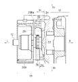
【解決手段】カムチェーンを介してクランクシャフト12及びカムシャフトが連結され、シリンダブロックの側部に略鉛直方向に沿って配置構成されたカムチェーントンネル30内でカムチェーンが走行する。クランクケース11の側壁と側壁から突出するクランクシャフト12の端部に取り付けた回転体20Bとの間にカムチェーンが配設され、カムチェーンの引張り側に沿ってクランクケースの側壁から突出するガイドリブ39を付設する。
【選択図】図8
Description
クランクケースの側壁とこの側壁から突出する前記クランクシャフトの端部に取り付けた回転体との間に前記カムチェーンが配設され、このカムチェーンの引張り側に沿って前記クランクケースの側壁から突出するガイドリブを付設したことを特徴とする。
図1は、本発明に係る自動二輪車100の側面図である。先ず、図1を用いて、自動二輪車100の全体構成について説明する。なお、図1を含め、以下の説明で用いる図においては、必要に応じて車両の前方を矢印Frにより、車両の後方を矢印Rrにより示し、また、車両の側方右側を矢印Rにより、車両の側方左側を矢印Lにより示す。
先ずここで、オイルポンプ23(スカベンジポンプ)とオイルポンプ24(フィードポンプ)とを含んで構成される潤滑系において、セミドライサンプの潤滑方式が採用される。マグネト室18に滞留するオイルはオイルポンプ23によって吸引されるが、その油面はマグネトロータ20Bのオイル攪拌抵抗を減少させるべく低く設定されている。なお、オイル攪拌抵抗の減少によりエンジン出力の向上を図ることができる。一方、マグネト室18内のオイル油面を下げるとオイル絶対量が減少し、そのままではカムチェーン29等の潤滑に対して必ずしも有利ではない。
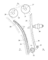
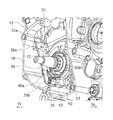
また、カムチェーン29の引張り側においてカムチェーンガイド34の背面側にガイドリブ39を隣接配置することで、オイルを的確に捕集すると共に円滑に流通させることが可能になる。
この場合、ガイドリブ40は、カムチェーン29及びドライブスプロケット33の噛合領域に略対応するように延設され、これによりオイルをカムチェーン29に対して極めて噛み込み易くし、潤滑効率を有効に高めることが可能になる。
ガイドリブ39の突出高さh1やガイドリブ40の突出高さh2、あるいはガイドリブ40の延出長さ(円周長)等は、必要に応じて適宜設定可能である。
Claims (6)
- カムチェーンを介してクランクシャフト及びカムシャフトが連結され、シリンダブロックの側部に略鉛直方向に沿って配置構成されたカムチェーントンネル内で前記カムチェーンが走行する自動二輪車エンジンにおいて、
クランクケースの側壁とこの側壁から突出する前記クランクシャフトの端部に取り付けた回転体との間に前記カムチェーンが配設され、このカムチェーンの引張り側に沿って前記クランクケースの側壁から突出するガイドリブを付設したことを特徴とする自動二輪車エンジンのカムチェーン潤滑構造。 - 前記カムチェーンはその引張り側にてカムチェーンガイドにより走行ガイドされ、前記ガイドリブは、前記カムチェーンガイドの前記カムチェーンとは反対側に隣接配置されることを特徴とする請求項1に記載の自動二輪車エンジンのカムチェーン潤滑構造。
- 前記クランクケースの側壁、前記回転体の側面及び前記ガイドリブにより、前記カムチェーン及び前記カムチェーンガイドを囲繞するように配置したことを特徴とする請求項2に記載の自動二輪車エンジンのカムチェーン潤滑構造。
- 前記クランクシャフトに取り付けたカムチェーン駆動用ドライブスプロケットの外周域に沿って、前記クランクケースの側壁から突出する第2のガイドリブを付設したことを特徴とする請求項1〜3のいずれか1項に記載の自動二輪車エンジンのカムチェーン潤滑構造。
- 前記第2のガイドリブは、前記カムチェーン及び前記ドライブスプロケットの噛合領域に略対応するように延設されることを特徴とする請求項4に記載の自動二輪車エンジンのカムチェーン潤滑構造。
- 前記回転体が収容されるマグネト室に滞留するオイルを吸引するスカベンジポンプを有し、このスカベンジポンプから吐出されるオイルの一部を、前記カムチェーンに対して噴射するようにしたことを特徴とする請求項1〜5のいずれか1項に記載の自動二輪車エンジンのカムチェーン潤滑構造。
Priority Applications (1)
| Application Number | Priority Date | Filing Date | Title |
|---|---|---|---|
| JP2009181890A JP5353538B2 (ja) | 2009-08-04 | 2009-08-04 | 自動二輪車エンジンのカムチェーン潤滑構造 |
Applications Claiming Priority (1)
| Application Number | Priority Date | Filing Date | Title |
|---|---|---|---|
| JP2009181890A JP5353538B2 (ja) | 2009-08-04 | 2009-08-04 | 自動二輪車エンジンのカムチェーン潤滑構造 |
Publications (3)
| Publication Number | Publication Date |
|---|---|
| JP2011032977A true JP2011032977A (ja) | 2011-02-17 |
| JP2011032977A5 JP2011032977A5 (ja) | 2012-08-23 |
| JP5353538B2 JP5353538B2 (ja) | 2013-11-27 |
Family
ID=43762291
Family Applications (1)
| Application Number | Title | Priority Date | Filing Date |
|---|---|---|---|
| JP2009181890A Active JP5353538B2 (ja) | 2009-08-04 | 2009-08-04 | 自動二輪車エンジンのカムチェーン潤滑構造 |
Country Status (1)
| Country | Link |
|---|---|
| JP (1) | JP5353538B2 (ja) |
Cited By (1)
| Publication number | Priority date | Publication date | Assignee | Title |
|---|---|---|---|---|
| JP2015063906A (ja) * | 2013-09-24 | 2015-04-09 | 本田技研工業株式会社 | 内燃機関のオイルレベルゲージ用通路 |
Citations (3)
| Publication number | Priority date | Publication date | Assignee | Title |
|---|---|---|---|---|
| JPS6340510U (ja) * | 1986-09-01 | 1988-03-16 | ||
| JPH08218835A (ja) * | 1995-02-17 | 1996-08-27 | Nissan Motor Co Ltd | エンジンのオイル戻し構造 |
| JP2005291041A (ja) * | 2004-03-31 | 2005-10-20 | Kawasaki Heavy Ind Ltd | エンジンのブリーザ装置 |
-
2009
- 2009-08-04 JP JP2009181890A patent/JP5353538B2/ja active Active
Patent Citations (3)
| Publication number | Priority date | Publication date | Assignee | Title |
|---|---|---|---|---|
| JPS6340510U (ja) * | 1986-09-01 | 1988-03-16 | ||
| JPH08218835A (ja) * | 1995-02-17 | 1996-08-27 | Nissan Motor Co Ltd | エンジンのオイル戻し構造 |
| JP2005291041A (ja) * | 2004-03-31 | 2005-10-20 | Kawasaki Heavy Ind Ltd | エンジンのブリーザ装置 |
Cited By (1)
| Publication number | Priority date | Publication date | Assignee | Title |
|---|---|---|---|---|
| JP2015063906A (ja) * | 2013-09-24 | 2015-04-09 | 本田技研工業株式会社 | 内燃機関のオイルレベルゲージ用通路 |
Also Published As
| Publication number | Publication date |
|---|---|
| JP5353538B2 (ja) | 2013-11-27 |
Similar Documents
| Publication | Publication Date | Title |
|---|---|---|
| JP4698623B2 (ja) | 内燃機関のブリーザ装置 | |
| JP3965960B2 (ja) | 自動二輪車のブリーザ装置 | |
| US8316816B2 (en) | Internal combustion engine and vehicle having the internal combustion engine | |
| US7690367B2 (en) | Internal combustion engine and vehicle having the internal combustion engine | |
| JP3820970B2 (ja) | 自動二輪車の潤滑油冷却構造 | |
| JP5117310B2 (ja) | 内燃機関 | |
| JP5203739B2 (ja) | ベルト式無段変速機の冷却構造 | |
| JP4467335B2 (ja) | エンジンにおける潤滑構造 | |
| JP4512011B2 (ja) | 内燃機関 | |
| JP4953901B2 (ja) | 水冷式内燃機関のオイル冷却装置 | |
| JP5353538B2 (ja) | 自動二輪車エンジンのカムチェーン潤滑構造 | |
| CN101713313B (zh) | 发动机的油面计配置结构 | |
| JP3470355B2 (ja) | ドライサンプエンジンのオイル通路 | |
| JP2011105148A (ja) | 車両用パワーユニット | |
| JP2011047366A (ja) | 自動二輪車エンジンの潤滑装置 | |
| JP6102468B2 (ja) | エンジンのブリーザ構造 | |
| WO2011132574A1 (ja) | エンジンのオイル通路構造 | |
| JP5823360B2 (ja) | 内燃機関の潤滑油供給構造 | |
| JP7447762B2 (ja) | 動力伝達機構の潤滑構造 | |
| JP3835426B2 (ja) | スクータ型車両 | |
| JP2011047370A (ja) | エンジンのオイルドレイン構造 | |
| JP2005233012A (ja) | 内燃機関本体へのラジエータ取り付け構造 | |
| JP2006090241A (ja) | 自動二輪車の4サイクルエンジン | |
| JP2010084652A (ja) | 内燃機関 | |
| JP2011047360A (ja) | エンジンのオイルジェット装置 |
Legal Events
| Date | Code | Title | Description |
|---|---|---|---|
| A621 | Written request for application examination |
Free format text: JAPANESE INTERMEDIATE CODE: A621 Effective date: 20120601 |
|
| A521 | Written amendment |
Free format text: JAPANESE INTERMEDIATE CODE: A523 Effective date: 20120710 |
|
| A131 | Notification of reasons for refusal |
Free format text: JAPANESE INTERMEDIATE CODE: A131 Effective date: 20130528 |
|
| A977 | Report on retrieval |
Free format text: JAPANESE INTERMEDIATE CODE: A971007 Effective date: 20130531 |
|
| A521 | Written amendment |
Free format text: JAPANESE INTERMEDIATE CODE: A523 Effective date: 20130705 |
|
| TRDD | Decision of grant or rejection written | ||
| A01 | Written decision to grant a patent or to grant a registration (utility model) |
Free format text: JAPANESE INTERMEDIATE CODE: A01 Effective date: 20130730 |
|
| A977 | Report on retrieval |
Free format text: JAPANESE INTERMEDIATE CODE: A971007 Effective date: 20130801 |
|
| A61 | First payment of annual fees (during grant procedure) |
Free format text: JAPANESE INTERMEDIATE CODE: A61 Effective date: 20130812 |
|
| R151 | Written notification of patent or utility model registration |
Ref document number: 5353538 Country of ref document: JP Free format text: JAPANESE INTERMEDIATE CODE: R151 |