JP2011069191A - Construction method for moving support part in bridge - Google Patents
Construction method for moving support part in bridge Download PDFInfo
- Publication number
- JP2011069191A JP2011069191A JP2010254249A JP2010254249A JP2011069191A JP 2011069191 A JP2011069191 A JP 2011069191A JP 2010254249 A JP2010254249 A JP 2010254249A JP 2010254249 A JP2010254249 A JP 2010254249A JP 2011069191 A JP2011069191 A JP 2011069191A
- Authority
- JP
- Japan
- Prior art keywords
- support
- bearing
- upper structure
- existing
- boss
- Prior art date
- Legal status (The legal status is an assumption and is not a legal conclusion. Google has not performed a legal analysis and makes no representation as to the accuracy of the status listed.)
- Granted
Links
- 238000010276 construction Methods 0.000 title claims abstract description 25
- 238000000034 method Methods 0.000 claims description 27
- 230000001483 mobilizing effect Effects 0.000 claims description 6
- 239000004570 mortar (masonry) Substances 0.000 claims description 3
- 230000006378 damage Effects 0.000 abstract description 7
- 230000033001 locomotion Effects 0.000 description 12
- 229910000831 Steel Inorganic materials 0.000 description 6
- 239000010959 steel Substances 0.000 description 6
- 239000000463 material Substances 0.000 description 5
- 239000010935 stainless steel Substances 0.000 description 5
- 229910001220 stainless steel Inorganic materials 0.000 description 5
- XEEYBQQBJWHFJM-UHFFFAOYSA-N Iron Chemical compound [Fe] XEEYBQQBJWHFJM-UHFFFAOYSA-N 0.000 description 4
- 238000002955 isolation Methods 0.000 description 4
- 238000010586 diagram Methods 0.000 description 3
- 239000004810 polytetrafluoroethylene Substances 0.000 description 3
- 229920001343 polytetrafluoroethylene Polymers 0.000 description 3
- 238000006243 chemical reaction Methods 0.000 description 2
- 238000013016 damping Methods 0.000 description 2
- 238000009434 installation Methods 0.000 description 2
- 229910052742 iron Inorganic materials 0.000 description 2
- 230000003014 reinforcing effect Effects 0.000 description 2
- 239000004952 Polyamide Substances 0.000 description 1
- 230000001066 destructive effect Effects 0.000 description 1
- 239000006185 dispersion Substances 0.000 description 1
- 238000006073 displacement reaction Methods 0.000 description 1
- 238000005516 engineering process Methods 0.000 description 1
- 210000000744 eyelid Anatomy 0.000 description 1
- 239000000835 fiber Substances 0.000 description 1
- 239000002184 metal Substances 0.000 description 1
- 229910052751 metal Inorganic materials 0.000 description 1
- NJPPVKZQTLUDBO-UHFFFAOYSA-N novaluron Chemical compound C1=C(Cl)C(OC(F)(F)C(OC(F)(F)F)F)=CC=C1NC(=O)NC(=O)C1=C(F)C=CC=C1F NJPPVKZQTLUDBO-UHFFFAOYSA-N 0.000 description 1
- 230000002093 peripheral effect Effects 0.000 description 1
- 229920002647 polyamide Polymers 0.000 description 1
- 238000007634 remodeling Methods 0.000 description 1
- 239000011347 resin Substances 0.000 description 1
- 229920005989 resin Polymers 0.000 description 1
- 238000000926 separation method Methods 0.000 description 1
- BFKJFAAPBSQJPD-UHFFFAOYSA-N tetrafluoroethene Chemical group FC(F)=C(F)F BFKJFAAPBSQJPD-UHFFFAOYSA-N 0.000 description 1
- 229920001187 thermosetting polymer Polymers 0.000 description 1
- 238000003466 welding Methods 0.000 description 1
Images
Landscapes
- Bridges Or Land Bridges (AREA)
Abstract
Description
この発明は、橋梁における支承部の可動化工法に関し、より詳細には既設支承の撤去や改造を加えることなく支承部を可動化し、地震時の橋梁構成部材の破壊を防止する技術に関する。 The present invention relates to a method for mobilizing a support portion in a bridge, and more particularly to a technique for moving a support portion without removing or remodeling an existing support to prevent destruction of bridge components during an earthquake.
旧い耐震設計基準で設置された既設支承は、その固定方向(例えば、固定支承の場合は全方向、可動支承の場合は橋軸直角方向)に関して、レベル1地震時まで固定として設計されており、レベル2地震時では破壊してしまう。しかし、その破壊耐力は明確ではなく、支承の鉛直荷重支持機能に支障をきたすなどの損傷形態が不明確である。なお、レベル1,2地震動とは「道路橋示方書・同解説 V耐震設計偏」(社団法人 日本道路協会)で規定されている地震動のことである。
Existing bearings installed under the old seismic design standards are designed to be fixed until the
また、既設支承の可動方向(例えば可動支承の場合の橋軸方向)に関しては、過度の移動を制限するためにレベル1耐力で設計された移動制限装置が支承本体に組み込まれており、レベル2地震時では破壊してしまう。しかし、この場合も、その破壊耐力は明確でなく、移動制限装置のみならず上沓まで破損してしまうなどの損傷形態が不明確である。
In addition, with regard to the movable direction of the existing bearing (for example, the direction of the bridge axis in the case of the movable bearing), a movement limiting device designed with a
このように既設支承は破壊耐力が明確でないため、レベル2地震時に下部構造への影響が不明確となり、下部構造に想定外の地震時慣性力が作用してしまう。また、レベル2地震時に破壊しないように支承本体を補強し、耐力を増大させた場合には、下部構造の地震時慣性力の負担が増大することになる。
In this way, the existing bearings are not clearly destructive, so the impact on the lower structure becomes unclear during a
以上のような背景のもと、レベル2地震動に対応するため、従来は既設支承を新規の免震支承などに交換する工法が採用されている。しかしながら、新規な支承は高価なため経済性に劣るという難点がある。また、既設支承の交換は、施工性、施工コストの点で問題がある。すなわち、既設支承の交換にあたって、従来技術では支承下面の下部構造コンクリートの斫り、既設支承の撤去、台座コンクリートの設置、アンカーボルトの設置、新規支承の設置が必要となり、施工日数が増加し、また施工性が劣るため施工コストが増大する。
Based on the background described above, in order to cope with
また、既設支承の支承高は30cm程度と低く、下部構造のコンクリートを斫るには非常に狭隘な箇所での作業となり施工性に劣る。アンカーボルトの設置にあたっては、下部構造コンクリートに埋設された既設鉄筋を切断してしまうことがないように、予め電磁波レーダー等により探査した後に、既設鉄筋が無い位置にアンカーボルトを設置する必要がある。さらに、ピン支承は反力が非常に大きい場合があるため、取り替えできないことがある。 In addition, the bearing height of the existing bearing is as low as about 30 cm, and the work in a very narrow place is inferior in workability for grinding the concrete of the lower structure. When installing the anchor bolt, it is necessary to install the anchor bolt at a position where there is no existing reinforcing bar after exploring with electromagnetic wave radar etc. in advance so as not to cut the existing reinforcing bar embedded in the lower structure concrete . In addition, the pin bearing may have a very large reaction force and may not be replaced.
特許文献1には、「既存支承を撤去することなく、この既存支承を改造してすべり支承化し、既設橋桁下面と既設橋脚上面または既設橋脚側面との間に免震装置を配設する」(請求項1)橋梁の免震工法が開示されている。しかしながら、この従来技術は、発明の詳細な説明を参照すると、アンカーバーは撤去することなく残しているものの、上沓及び下沓を新たに設置しており(段落0014、段落0015及び図2(a))、実質的に新たな支承に交換しているといわざるをえない。しかも、この新たな支承は、支承自体がすべり機能を有するすべり支承である。
この発明は上記のような技術的背景に基づいてなされたものであって、次の目的を達成するものである。
この発明の目的は、既設支承を新たな支承に取り換えることなく支承部を可動化し、これによって大地震時において支承の破壊を防止し、また下部構造の負担を軽減することができ、また施工も極めて簡単で施工コストも安価に抑えることができる、橋梁における支承部の可動化工法を提供することにある。
The present invention has been made based on the technical background as described above, and achieves the following object.
The object of the present invention is to make the support part movable without replacing the existing support with a new support, thereby preventing damage to the support in the event of a large earthquake, reducing the burden on the substructure, and construction. It is an object of the present invention to provide a method for mobilizing a support portion in a bridge that is extremely simple and can be kept at a low construction cost.
この発明は上記課題を達成するために、次のような手段を採用している。
すなわち、この発明は、上部構造と下部構造との間に既設支承が設置されている支承部の可動化工法であって、
前記既設支承の上面に前記上部構造との間ですべりを生じるすべりプレートを設置することを特徴とする橋梁における支承部の可動化工法にある。
The present invention employs the following means in order to achieve the above object.
That is, the present invention is a mobilization method of a support part in which an existing support is installed between the upper structure and the lower structure,
The method of mobilizing a support portion in a bridge is characterized in that a slip plate is provided on the upper surface of the existing support to generate a slip between the upper structure.
この発明は、より具体的には、下面にソールプレートが設けられた上部構造と下部構造との間に、既設支承がその上面に設けられたボスが前記ソールプレートに設けられたボス穴に嵌合した状態で設置されている支承部の可動化工法であって、
前記上部構造をジャッキアップして、前記ソールプレート及び前記ボスを切断除去した後、
前記上部構造の下面に上部構造側すべりプレートを設置するとともに、前記既設支承の上面に前記上部構造側すべりプレートとの間ですべりを生じる支承側すべりプレートを設置し、
前記上部構造をジャッキダウンすることを特徴とする。
More specifically, according to the present invention, a boss provided on an upper surface of an existing support is fitted in a boss hole provided on the sole plate between an upper structure and a lower structure provided with a sole plate on a lower surface. It is a mobilization method of the support part installed in the combined state,
After jacking up the upper structure and cutting and removing the sole plate and the boss,
An upper structure side sliding plate is installed on the lower surface of the upper structure, and a bearing side sliding plate that causes a slip between the upper structure side sliding plate is installed on the upper surface of the existing bearing,
The upper structure is jacked down.
さらに、この発明は、下面にソールプレートが設けられた上部構造と下部構造との間に、既設支承がその上面に設けられたボスが前記ソールプレートに設けられたボス穴に嵌合した状態で設置されている支承部の可動化工法であって、
前記既設支承周囲の下部構造コンクリートを斫ったうえ、該既設支承をジャッキダウンして、前記ソールプレート及び前記ボスを切断除去した後、
前記上部構造の下面に上部構造側すべりプレートを設置するとともに、前記既設支承の上面に前記上部構造側すべりプレートとの間ですべりを生じる支承側すべりプレートを設置し、
前記既設支承をジャッキアップして、前記下部構造コンクリートの斫り部分にモルタルを充填することを特徴とする。
Further, according to the present invention, the boss provided on the upper surface of the existing support is fitted in the boss hole provided on the sole plate between the upper structure and the lower structure provided with the sole plate on the lower surface. It is a mobilization method of the installed bearing part,
After crushing the lower structural concrete around the existing bearing, jacking down the existing bearing, cutting and removing the sole plate and the boss,
An upper structure side sliding plate is installed on the lower surface of the upper structure, and a bearing side sliding plate that causes a slip between the upper structure side sliding plate is installed on the upper surface of the existing bearing,
The existing support is jacked up, and a mortar is filled in the turned portion of the lower structural concrete.
前記ボスを切断除去する際にその一部を残し、その残されたボスを前記支承側すべりプレートに設けた穴に嵌合させるようにしてもよい。また、前記上部構造と前記既設支承との間に、前記上部構造側すべりプレート及び前記支承側すべりプレートを貫通し、両者のすべり面において切断破壊面を有するノックオフ型セットボルトを設けるようにしてもよい。前記上部構造側すべりプレートと前記支承側すべりプレートとの間の摩擦係数を調整して、これらすべりプレートを設置するようにしてもよい。 When the boss is cut and removed, a part of the boss may be left, and the remaining boss may be fitted into a hole provided in the bearing-side slide plate. Further, a knock-off type set bolt that penetrates the upper structure side sliding plate and the bearing side sliding plate between both the upper structure and the existing bearing and has a cut fracture surface on both sliding surfaces may be provided. Good. You may make it install these slide plates by adjusting the friction coefficient between the said upper structure side slide plate and the said support side slide plate.
この発明工法によれば、上部構造が支承本体の移動機能によって移動するのではなく、上部構造が既設支承に対して移動するようにするので、既設支承を高価な新規な支承に取り替えずとも大地震時における支承の破壊を防止し、また下部構造の負担を軽減することができる。また、下部構造コンクリートの斫り作業を不要又は最小限に抑えることができ、アンカーボルトの設置作業も不要であるので、施工も極めて簡単で施工コストも安価に抑えることができる According to this construction method, the upper structure is not moved by the moving function of the support body, but the upper structure is moved with respect to the existing support. Therefore, the existing support is not required to be replaced with an expensive new support. It is possible to prevent damage to the bearing during an earthquake and to reduce the burden on the substructure. In addition, it is possible to minimize or minimize the work of turning the substructure concrete, and it is also unnecessary to install anchor bolts, so that the construction is extremely simple and the construction cost can be kept low.
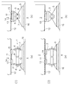
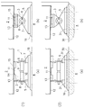
この発明の実施形態を図面を参照しながら以下に説明する。図1〜図3に示す実施形態は、既設支承として固定支承の1つであるピン支承が設置された支承部を可動化する例である。各図に付された連続番号(1)〜(6)は施工手順を示し、各施工手順図における(a),(b)はそれぞれ橋軸方向矢視断面図及び橋軸直角方向矢視図を示している。 Embodiments of the present invention will be described below with reference to the drawings. The embodiment shown in FIG. 1 to FIG. 3 is an example in which a bearing portion in which a pin bearing, which is one of fixed bearings, is installed as an existing bearing is moved. The serial numbers (1) to (6) attached to each figure show the construction procedure, and (a) and (b) in each construction procedure figure are the cross-sectional view in the direction of the bridge axis and the arrow in the direction perpendicular to the bridge axis, respectively. Is shown.
まず、既設ピン支承の設置状態を示す図1(1)を参照して、ピン支承の概要について説明する。ピン支承1は橋桁である上部構造2の下面に固定される上沓3と、橋脚や橋台である下部構造4の上面に固定される下沓5とを備えている。上沓3の下面及び下沓5の上面には半円筒形ボス部6,7が形成されている。これらのボス部6,7は互いに対向して略円筒形のボス部となり、このボス部にピン8が嵌っている。これにより、上沓3は下沓5に対して鉛直方向に回転可能である。
First, the outline of the pin support will be described with reference to FIG. 1 (1) showing the installation state of the existing pin support. The
半円筒形ボス部6,7の内周中央には半環状突起9,10がそれぞれ設けられている。一方、ピン8には、これらの半環状突起9,10が嵌まる環状溝部が設けられている。これにより上沓3は下沓5に対して橋軸直角方向に移動できないようになっている。
上沓3の上面にはボス11が設けられている。図には上部構造2として鋼桁が示され、そのフランジ12の下面にはソールプレート13が溶接により固定されている。このソールプレート13にはボス穴14が設けられている。上沓3はボス11がボス穴14に嵌合された状態で、フランジ12に取り付けられるセットボルト15により上部構造2に固定されている。
A
下部構造4にはベースプレート16が図示しないアンカーボルトにより固定され、下沓5はこのベースプレート16の上面に固定されている。下部構造4としては、図示の例では橋台が示されている。
A
上記のようなピン支承1が設置された支承部を可動化するためには、まず、図1(2)に示すように、セットボルト15を撤去して上部構造2をジャッキアップする。ジャッキアップ量は後述するワイヤソーなどによる切断施工が可能なわずかな量(20mm程度)であり、橋梁の他の設備、例えば既設伸縮装置の排水装置などへの影響がほとんどない。
In order to move the support portion on which the
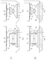
次に、図2(3)に示すように、ワイヤソーなどの切断機によりボス11を切断する除去する。このときボス11の一部は残しておく。また、ソールプレート13も、その溶接部をグラインダー切断機などの切断機やガスガウンジングにより切断し、撤去する。図において鎖線で示した部分が切断除去部である。
Next, as shown in FIG. 2 (3), the
次に、図2(4)に示すように、上部構造2のフランジ12の下面に上部構造側すべりプレート17を取り付ける。上部構造側すべりプレート17としては、例えばステンレス(SUS)板が用いられる。この上部構造側すべりプレート17は、フランジ12に孔を明け、これに挿入される取付けボルト18によって取り付けられる。上部構造2のフランジ12は、橋台上において桁端部が橋軸方向に沿って傾斜しているので、フランジ12に取り付けられる上部構造側すべりプレート17の取付け面も同方向に沿って傾斜するようにテーパ加工を施す。
Next, as shown in FIG. 2 (4), the upper structure
次に、図3(5)に示すように、上沓3の上面に支承側すべりプレート19を設置する。支承側すべりプレート19は、鋼材からなる本体プレートの表面に凹部を形成し、この凹部にすべり材22(図4参照)を嵌め込んで形成される。すべり材22としては、例えば四フッ化エチレン(PTFE)板が用いられる。支承側すべりプレート19は外形寸法が上沓3の上面の外形寸法とほぼ同じ大きさのもので、中央にボス11の残部11aが嵌まる穴20が設けられている。支承側すべりプレート19は穴20に残部11aが嵌った状態で上沓3の上面に単に載置されるだけである。このように、ボス11の一部を残部11aとして残しておくことにより、残部11aを利用して支承側すべりプレート19を位置決めすることができ、その据え付けが容易となる。
Next, as shown in FIG. 3 (5), the bearing
次に、図3(6)に示すように、上部構造2をジャッキダウンする。この状態で、上部構造2は既設支承1に対して、具体的にはその上沓3に対して水平方向全方向にすべりを生ずるようになる。すなわち、常時、レベル1地震時及びレベル2地震時のいずれにおいても支承部が可動化することになる。
Next, as shown in FIG. 3 (6), the
この発明工法は、上述のピン支承が設置されている支承部に限らず、既設支承によって固定方向が設定された種々の支承部に適用可能である。具体的には、既設支承としてゴム支承が設置された支承部や、既設支承として線接触支承、上述のピン支承、ピンローラ支承、支承板支承、球面支承、円柱面支承、点接触支承などの鋼製支承が設置された支承部に適用可能である。 This invention construction method is applicable not only to the bearing part in which the above-mentioned pin bearing is installed, but also to various bearing parts in which the fixing direction is set by the existing bearing. Specifically, steel bearings such as bearings with rubber bearings installed as existing bearings, line contact bearings as existing bearings, pin bearings described above, pin roller bearings, bearing plate bearings, spherical bearings, cylindrical surface bearings, point contact bearings, etc. It can be applied to a bearing part in which a manufactured bearing is installed.
この発明工法により可動化した支承部は、上部構造が支承本体の移動機能によって移動するのではなく、上部構造が既設支承に対して移動するので、既設支承の移動制限距離に依存せず、移動量を設定できる。さらに、大移動量にも対応することが可能である。上記実施形態では、上部構造2のフランジ12に上部構造側すべりプレート17を設けたが、上部構造側すべりプレート17を設置せずに、ソールプレート13を切断除去したフランジ12と支承側すべりプレート19との間ですべりを生じさせるようにすることも可能である。
The support part mobilized by the method of the present invention is not moved by the moving function of the support body, but the upper structure moves relative to the existing support, so it does not depend on the movement limit distance of the existing support and moves. You can set the amount. Furthermore, it is possible to cope with a large amount of movement. In the above embodiment, the upper structure
上部構造側すべりプレート17と支承側すべりプレート19の材質の組み合わせを次のように適宜選択することにより、両者間の摩擦係数を調整することができる。
(1) 高摩擦(摩擦係数:0.2〜0.5)とし地震時の摩擦減衰を期待する場合
・燒結金属系すべり材とステンレスの組み合わせ
・鋼と鋼の組み合わせ
・鉄と亜鉛めっきの組み合わせ
(2) 中摩擦(摩擦係数:0.1〜0.15)とし地震時の摩擦減衰を期待する場合
・PTFEとステンレスの組み合わせ
・PTFEと鋼の組み合わせ
(3) 低摩擦(摩擦係数:0.02〜0.08)とし地震時の摩擦減衰を期待せずに地震力を遮断する場合
・繊維強化熱硬化樹脂とステンレスの組み合わせ
・ポリアミドとステンレスの組み合わせ
The friction coefficient between the two can be adjusted by appropriately selecting the combination of materials of the upper structure
(1) When high friction (coefficient of friction: 0.2 to 0.5) is expected to reduce friction during an earthquake ・ Combination of sintered metal-based sliding material and stainless steel ・ Combination of steel and steel ・ Combination of iron and galvanization
(2) When friction reduction during an earthquake is expected with medium friction (friction coefficient: 0.1 to 0.15) ・ Combination of PTFE and stainless steel ・ Combination of PTFE and steel
(3) When using low friction (friction coefficient: 0.02 to 0.08) to cut off the seismic force without expecting frictional damping during an earthquake ・ Combination of fiber reinforced thermosetting resin and stainless steel ・ Combination of polyamide and stainless steel
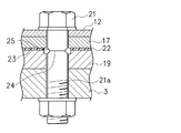
可動化した支承部は、他の部材と組み合わせることで、種々の形態を採ることができる。例えば、上述の既設ピン支承1を有する支承部の場合、図3(6)に示すように、ノックオフ型セットボルト21を用いて、上部構造2と既設支承1とを固定することにより、支承部をレベル1地震動までは固定、レベル2地震時に可動とすることができる。
The movable support portion can take various forms by being combined with other members. For example, in the case of the above-described bearing portion having the existing pin bearing 1, as shown in FIG. 3 (6), the
ノックオフ型セットボルト21は、図4に示すように、その軸部21aに外径を小さくしたくびれ部25を設けることにより、水平荷重によりせん断破壊するようにしたボルトであり、符号24はせん断破壊面を示している。上部構造側すべりプレート17と支承側すべりプレート19、具体的にはそのすべり材22との接する面が地震時すべり面23であり、ノックオフ型セットボルト21はせん断破壊面24が地震時すべり面23近くに位置するように取り付けられる。
As shown in FIG. 4, the knock-off type set
上記のようにノックオフ型ボルト21を用いた支承部においては、レベル1地震時まではノックオフ型ボルト21によって上部構造2と既設支承1とが固定されるので、上部構造2は既設支承1に対してすべらず、上部構造2は下部構造4に対して水平移動しない。しかし、レベル2地震動になるとノックオフ型ボルト21がせん断破壊面24に沿って破壊し、上部構造2が既設支承1に対してすべりを生じるようになる。その結果、レベル2地震時においても既設支承1は破壊することがなく、また下部構造4にも過大な負荷が加わらない。
In the bearing portion using the knock-
また、別の支承部形態として、鉛直荷重は既設支承を利用し、水平荷重を制震デバイスや、免震デバイス、あるいは反力分散デバイスなどが分担するタイプB(「道路橋示方書・同解説 V耐震設計偏」(社団法人 日本道路協会))の機能分離型支承部構造とすることが可能である。 In addition, as another form of bearing part, vertical load uses existing bearings, and horizontal load is shared by seismic control device, seismic isolation device, reaction force dispersion device, etc. Type B (“Road Bridge Specification / Description” It is possible to adopt a function-separated bearing structure of “V seismic design bias” (Japan Road Association).
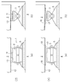
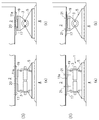
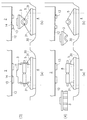
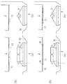
図5〜図8は別の実施形態を示している。この実施形態も、既設支承として固定支承の1つであるピン支承が設置された支承部を可動化する例である。上記実施形態と同様に、各図に付された連続番号(1)〜(8)は施工手順を示し、各施工手順図における(a),(b)はそれぞれ橋軸方向矢視断面図及び橋軸直角方向矢視図を示している。 5 to 8 show another embodiment. This embodiment is also an example in which a bearing portion in which a pin bearing which is one of fixed bearings is installed as an existing bearing is movable. As in the above embodiment, the serial numbers (1) to (8) attached to each figure indicate the construction procedure, and (a) and (b) in each construction procedure diagram are respectively a cross-sectional view in the direction of the bridge axis and The bridge axis perpendicular direction view is shown.
図5(1)は既設ピン支承1の設置状態を示す図であり、ピン支承の構造は上記実施形態に関して説明したものと同様である。この実施形態では、上部構造2はジャッキアップせずに、既設ピン支承1をジャッキダウンする。そのために、図5(2)に示すように、既設ピン支承1周囲の下部構造コンクリートを斫り、斫り部30を形成する。このとき、下沓5を下部構造4に固定しているアンカーボルト31は撤去しないで、そのまま残しておく。
FIG. 5 (1) is a view showing an installed state of the existing
次に、図6(3)に示すように、図示しない治具を介して既設ピン支承1をジャッキに支持し、アンカーボルト31をガイドとして既設ピン支承1をジャッキダウンさせる。これによって、上沓3のボス11はボス穴14から抜け出るので、図6(4)に示すように、下沓5から上沓3を取り外す。取り外した上沓3は、施工現場以外の場所に運び、ボス11を上記実施形態と同様の手段により切断除去する。
Next, as shown in FIG. 6 (3), the existing
次に、図7(5)に示すように、ソールプレート13を上記実施形態と同様な手段により切断除去する。そして、図7(6)に示すように、上部構造2のフランジ12下面に上部構造側すべりプレート17を取付けボルト18により取り付ける。また、図8(7)に示すように、取り外した上沓3に支承側すべりプレート19をセットし、この上沓3を再び下沓5に取り付け、既設ピン支承1を復元する。
Next, as shown in FIG. 7 (5), the
次に、図8(8)に示すように、既設ピン支承1を上部構造側すべりプレート17と支承側すべりプレート19とが接するまでジャッキアップする。この状態で斫り部30にモルタル32を充填し、硬化させる。また、上記実施形態で示したと同様に、ノックオフ型セットボルト21を用いて、上部構造2と既設支承1とを固定する。
Next, as shown in FIG. 8 (8), the existing pin bearing 1 is jacked up until the upper structure
以上のように、この発明工法によれば、上部構造が支承本体の移動機能によって移動するのではなく、上部構造が既設支承に対して移動するので、既設支承を高価な新規な支承に取り替える必要がない。このため、下部構造コンクリートの斫り作業や、アンカーボルトの設置作業を省略することができる。また、タイプBの機能分離型支承部構造の一部として既設支承を利用することが可能となるため、変位制限構造を省略することが可能となる。 As described above, according to the method of the present invention, the upper structure is not moved by the moving function of the support body, but the upper structure is moved with respect to the existing bearing. Therefore, it is necessary to replace the existing bearing with an expensive new bearing. There is no. For this reason, the work of turning the lower structural concrete and the work of installing the anchor bolt can be omitted. Further, since the existing support can be used as a part of the type B function separation type support part structure, the displacement limiting structure can be omitted.
この発明により、支承部をその固定方向に関して可動化し、さらには必要に応じて摩擦減衰を付加することで、レベル2地震時の慣性力を作用させないかもしくは低減することができる。その結果、支承部を可動化した橋脚ひいては橋梁全体が受けるダメージを最小限とすることができる。また、レベル2地震時において既設支承の移動制限距離を超える地震時移動量が発生した場合でも、既設支承にダメージを与えることがない。さらに、各種デバイスと組み合わせることで、既設支承を利用した機能分離型支承部として、レベル2地震時の慣性力を低減することができる。
According to the present invention, the inertial force at the time of the
1 ピン支承(既設支承)
2 上部構造
3 上沓
4 下部構造
5 下沓
8 ピン
11 ボス
11a ボス残部
12 フランジ
14 ボス穴
15 セットボルト
17 上部構造側すべりプレート
19 下部構造側すべりプレート
21 ノックオフ型セットボルト
22 すべり材
23 すべり面
24 せん断破壊面
1 Pin support (existing support)
2
Claims (6)
前記既設支承の上面に前記上部構造との間ですべりを生じるすべりプレートを設置することを特徴とする橋梁における支承部の可動化工法。 Between the superstructure and the substructure, it is a mobilization method of the support part where the existing support is installed,
A method for mobilizing a support portion in a bridge, wherein a slip plate is formed on the upper surface of the existing support to generate a slip with the superstructure.
前記上部構造をジャッキアップして、前記ソールプレート及び前記ボスを切断除去した後、
前記上部構造の下面に上部構造側すべりプレートを設置するとともに、前記既設支承の上面に前記上部構造側すべりプレートとの間ですべりを生じる支承側すべりプレートを設置し、
前記上部構造をジャッキダウンすることを特徴とする橋梁における支承部の可動化工法。 Between the upper structure and the lower structure provided with the sole plate on the lower surface, the existing support is installed in a state where the boss provided on the upper surface is fitted in the boss hole provided on the sole plate. The mobilization method of
After jacking up the upper structure and cutting and removing the sole plate and the boss,
An upper structure side sliding plate is installed on the lower surface of the upper structure, and a bearing side sliding plate that causes a slip between the upper structure side sliding plate is installed on the upper surface of the existing bearing,
A method for mobilizing a support portion in a bridge, wherein the upper structure is jacked down.
前記既設支承周囲の下部構造コンクリートを斫ったうえ、該既設支承をジャッキダウンして、前記ソールプレート及び前記ボスを切断除去した後、
前記上部構造の下面に上部構造側すべりプレートを設置するとともに、前記既設支承の上面に前記上部構造側すべりプレートとの間ですべりを生じる支承側すべりプレートを設置し、
前記既設支承をジャッキアップして、前記下部構造コンクリートの斫り部分にモルタルを充填することを特徴とする橋梁における支承部の可動化工法。 Between the upper structure and the lower structure provided with the sole plate on the lower surface, the existing support is installed in a state where the boss provided on the upper surface is fitted in the boss hole provided on the sole plate. The mobilization method of
After crushing the lower structural concrete around the existing bearing, jacking down the existing bearing, cutting and removing the sole plate and the boss,
An upper structure side sliding plate is installed on the lower surface of the upper structure, and a bearing side sliding plate that causes a slip between the upper structure side sliding plate is installed on the upper surface of the existing bearing,
A method of mobilizing a support portion in a bridge, wherein the existing support is jacked up and mortar is filled in a ridge portion of the lower structural concrete.
Priority Applications (1)
| Application Number | Priority Date | Filing Date | Title |
|---|---|---|---|
| JP2010254249A JP5754920B2 (en) | 2010-11-12 | 2010-11-12 | Mobilization method of support part in bridge |
Applications Claiming Priority (1)
| Application Number | Priority Date | Filing Date | Title |
|---|---|---|---|
| JP2010254249A JP5754920B2 (en) | 2010-11-12 | 2010-11-12 | Mobilization method of support part in bridge |
Publications (2)
| Publication Number | Publication Date |
|---|---|
| JP2011069191A true JP2011069191A (en) | 2011-04-07 |
| JP5754920B2 JP5754920B2 (en) | 2015-07-29 |
Family
ID=44014701
Family Applications (1)
| Application Number | Title | Priority Date | Filing Date |
|---|---|---|---|
| JP2010254249A Active JP5754920B2 (en) | 2010-11-12 | 2010-11-12 | Mobilization method of support part in bridge |
Country Status (1)
| Country | Link |
|---|---|
| JP (1) | JP5754920B2 (en) |
Cited By (4)
| Publication number | Priority date | Publication date | Assignee | Title |
|---|---|---|---|---|
| CN102587273A (en) * | 2012-03-13 | 2012-07-18 | 上海材料研究所 | Method for enabling horizontal friction of support to be variable |
| JP2013036215A (en) * | 2011-08-08 | 2013-02-21 | Takada Kiko Co Ltd | Knock-off bolt |
| JP2014163054A (en) * | 2013-02-21 | 2014-09-08 | Takada Kiko Co Ltd | Existing support mobilizing method |
| JP2021042617A (en) * | 2019-09-13 | 2021-03-18 | 高田機工株式会社 | Knock-off type bolt and its mounting structure |
Citations (7)
| Publication number | Priority date | Publication date | Assignee | Title |
|---|---|---|---|---|
| JPS6076115U (en) * | 1983-10-25 | 1985-05-28 | 大成建設株式会社 | Dual-purpose shoes used in bridge extrusion construction method |
| JPH02221504A (en) * | 1989-02-23 | 1990-09-04 | Maeda Corp | Method for push-out processing pc bridge |
| JPH0941321A (en) * | 1995-07-28 | 1997-02-10 | Kajima Corp | Seismic isolation method for bridges using existing bearings |
| JPH11247133A (en) * | 1998-03-03 | 1999-09-14 | East Japan Railway Co | Bearing structure and repair method of bearing function |
| JP2001020223A (en) * | 1999-07-06 | 2001-01-23 | Dps Bridge Works Co Ltd | Modifying method of existing bridge beam support part |
| JP2003206510A (en) * | 2002-01-10 | 2003-07-25 | Kaimon:Kk | Function change repair construction method for existing elastic support |
| JP2004308108A (en) * | 2003-04-01 | 2004-11-04 | Bbm:Kk | Repair structure and repair construction method repaired to bearing device of functional discrete type using base plate of existing elastic support device |
-
2010
- 2010-11-12 JP JP2010254249A patent/JP5754920B2/en active Active
Patent Citations (7)
| Publication number | Priority date | Publication date | Assignee | Title |
|---|---|---|---|---|
| JPS6076115U (en) * | 1983-10-25 | 1985-05-28 | 大成建設株式会社 | Dual-purpose shoes used in bridge extrusion construction method |
| JPH02221504A (en) * | 1989-02-23 | 1990-09-04 | Maeda Corp | Method for push-out processing pc bridge |
| JPH0941321A (en) * | 1995-07-28 | 1997-02-10 | Kajima Corp | Seismic isolation method for bridges using existing bearings |
| JPH11247133A (en) * | 1998-03-03 | 1999-09-14 | East Japan Railway Co | Bearing structure and repair method of bearing function |
| JP2001020223A (en) * | 1999-07-06 | 2001-01-23 | Dps Bridge Works Co Ltd | Modifying method of existing bridge beam support part |
| JP2003206510A (en) * | 2002-01-10 | 2003-07-25 | Kaimon:Kk | Function change repair construction method for existing elastic support |
| JP2004308108A (en) * | 2003-04-01 | 2004-11-04 | Bbm:Kk | Repair structure and repair construction method repaired to bearing device of functional discrete type using base plate of existing elastic support device |
Non-Patent Citations (1)
| Title |
|---|
| JPN6015005175; 本荘清司、外4名: '"ノックオフ機能付き支承構造を用いた既設橋梁の耐震補強対策"' 構造工学論文集A Vol.55A, 200903, p.506-514 * |
Cited By (5)
| Publication number | Priority date | Publication date | Assignee | Title |
|---|---|---|---|---|
| JP2013036215A (en) * | 2011-08-08 | 2013-02-21 | Takada Kiko Co Ltd | Knock-off bolt |
| CN102587273A (en) * | 2012-03-13 | 2012-07-18 | 上海材料研究所 | Method for enabling horizontal friction of support to be variable |
| JP2014163054A (en) * | 2013-02-21 | 2014-09-08 | Takada Kiko Co Ltd | Existing support mobilizing method |
| JP2021042617A (en) * | 2019-09-13 | 2021-03-18 | 高田機工株式会社 | Knock-off type bolt and its mounting structure |
| JP7128786B2 (en) | 2019-09-13 | 2022-08-31 | 高田機工株式会社 | Knock-off type bolt mounting structure |
Also Published As
| Publication number | Publication date |
|---|---|
| JP5754920B2 (en) | 2015-07-29 |
Similar Documents
| Publication | Publication Date | Title |
|---|---|---|
| KR101659250B1 (en) | Bridge pc beam rising device for bridge bearing change | |
| KR102026083B1 (en) | One-way c.p.s jack having earthquake-proof function using for intensity reinforce mathod for bridge bearing and lifting method for structure using the same | |
| JP5754920B2 (en) | Mobilization method of support part in bridge | |
| KR101846125B1 (en) | Bridge upper plate increase device for bridge bearing change | |
| KR101564721B1 (en) | Construction method for replacing bridge bearing without damaging of lower structure | |
| JP2014240567A (en) | Fixing structure | |
| CN106758787A (en) | A kind of Precast Pier Columns mounting and positioning device | |
| JP2007040097A (en) | Displacement limiting device for bridge facility | |
| KR100845028B1 (en) | Seismic Strengthening Method of Existing Bridge | |
| JP6059555B2 (en) | Mobilization method for existing bearings | |
| JP6534628B2 (en) | Fallout prevention structure | |
| JP2006207119A (en) | Functional maintenance method of bridge bearing in case of earthquake, bolt for fixing the bridge bearing to lower structure and fixed construction of the bridge bearing and the lower structure | |
| JP3898509B2 (en) | Function change repair method for existing elastic bearings | |
| KR101341847B1 (en) | Seismic reinforce device structure for bridge and construction method | |
| JP2016008463A (en) | Bearing installation method and bearing structure | |
| JP2008038504A (en) | Method for improving antiseismic performance of bridge | |
| JP4395090B2 (en) | Replacement method for multi-function bearings on existing bridges | |
| JP7165555B2 (en) | Function-separated shock absorber | |
| JP5852475B2 (en) | Pile foundation reconstruction method | |
| JP2003206509A (en) | Function change repair construction method for existing elastic support | |
| CN116377847A (en) | An abutment structure and construction method with replaceable back wall | |
| CN105178184A (en) | Friction damper | |
| KR100722220B1 (en) | Seismic retrofit device for bridge port bearing | |
| JP2014077321A (en) | Earthquake strengthening method for existing steel bearing | |
| KR101860392B1 (en) | The seismic damping device on exiting falling prevention device |
Legal Events
| Date | Code | Title | Description |
|---|---|---|---|
| A621 | Written request for application examination |
Free format text: JAPANESE INTERMEDIATE CODE: A621 Effective date: 20130925 |
|
| A977 | Report on retrieval |
Free format text: JAPANESE INTERMEDIATE CODE: A971007 Effective date: 20140327 |
|
| A131 | Notification of reasons for refusal |
Free format text: JAPANESE INTERMEDIATE CODE: A131 Effective date: 20141014 |
|
| A521 | Request for written amendment filed |
Free format text: JAPANESE INTERMEDIATE CODE: A523 Effective date: 20141211 |
|
| A131 | Notification of reasons for refusal |
Free format text: JAPANESE INTERMEDIATE CODE: A131 Effective date: 20150210 |
|
| A521 | Request for written amendment filed |
Free format text: JAPANESE INTERMEDIATE CODE: A523 Effective date: 20150217 |
|
| TRDD | Decision of grant or rejection written | ||
| A01 | Written decision to grant a patent or to grant a registration (utility model) |
Free format text: JAPANESE INTERMEDIATE CODE: A01 Effective date: 20150519 |
|
| A61 | First payment of annual fees (during grant procedure) |
Free format text: JAPANESE INTERMEDIATE CODE: A61 Effective date: 20150526 |
|
| R150 | Certificate of patent or registration of utility model |
Ref document number: 5754920 Country of ref document: JP Free format text: JAPANESE INTERMEDIATE CODE: R150 |
|
| R250 | Receipt of annual fees |
Free format text: JAPANESE INTERMEDIATE CODE: R250 |
|
| R250 | Receipt of annual fees |
Free format text: JAPANESE INTERMEDIATE CODE: R250 |
|
| R250 | Receipt of annual fees |
Free format text: JAPANESE INTERMEDIATE CODE: R250 |