JP2011102731A - Ellipsometry device - Google Patents
Ellipsometry device Download PDFInfo
- Publication number
- JP2011102731A JP2011102731A JP2009257187A JP2009257187A JP2011102731A JP 2011102731 A JP2011102731 A JP 2011102731A JP 2009257187 A JP2009257187 A JP 2009257187A JP 2009257187 A JP2009257187 A JP 2009257187A JP 2011102731 A JP2011102731 A JP 2011102731A
- Authority
- JP
- Japan
- Prior art keywords
- imaging system
- magnification
- angle
- light
- ellipsometry
- Prior art date
- Legal status (The legal status is an assumption and is not a legal conclusion. Google has not performed a legal analysis and makes no representation as to the accuracy of the status listed.)
- Granted
Links
Images


Landscapes
- Microscoopes, Condenser (AREA)
Abstract
【課題】物体の微小構造を高コントラストかつ高倍率で観察できるうえ、物体面に対して法線方向観察側の位置に、物体面に接触又は近接して用いられる計測手段や操作手段などのための作業空間を確保できるエリプソメトリー装置を提供すること。
【解決手段】エリプソメトリー顕微鏡は、光源と偏光子と位相補償子とを備えると共に試料面SPに対して照明光L4を斜めに照射する斜め照明系と、結像系と、検光子23と、結像系による像を検出面25で検出する撮像素子24とを備える。結像系は、対物レンズ21を含む1次結像系10と、結像レンズ22を含む2次結像系11との複数段で構成されている。対物レンズ21の倍率M1(例えば1倍)を、結像レンズ22の倍率M2(例えば100倍)に比べ相対的に小さく設定することにより、対物レンズ21の光軸AX1と、1次結像系10の結像面P1とのなす角度θ1が相対的に大きく設定されている。
【選択図】図2In addition to being able to observe the microstructure of an object with high contrast and high magnification, it is for a measuring means or an operating means used in contact with or close to the object surface at a position on the normal direction observation side with respect to the object surface. To provide an ellipsometry device that can secure a working space.
An ellipsometry microscope includes a light source, a polarizer, and a phase compensator, and an oblique illumination system that obliquely illuminates illumination light L4 onto a sample surface SP, an imaging system, an analyzer 23, And an image sensor 24 that detects an image formed by the imaging system on the detection surface 25. The imaging system includes a plurality of stages of a primary imaging system 10 including an objective lens 21 and a secondary imaging system 11 including an imaging lens 22. By setting the magnification M1 (for example, 1 ×) of the objective lens 21 to be relatively smaller than the magnification M2 (for example, 100 ×) of the imaging lens 22, the optical axis AX1 of the objective lens 21 and the primary imaging system An angle θ1 formed with 10 image planes P1 is set to be relatively large.
[Selection] Figure 2
Description
本発明は、薄膜等の物体の膜厚分布を観察可能な偏光解析法(エリプソメトリー)を用いたエリプソメータやエリプソメトリー顕微鏡等のエリプソメトリー装置に関する。 The present invention relates to an ellipsometry apparatus such as an ellipsometer or an ellipsometry microscope using an ellipsometric method (ellipsometry) capable of observing the film thickness distribution of an object such as a thin film.
次世代ハードディスク装置では、ヘッドがディスクと接触しながら走行する潤滑方式への移行が予想されており、この場合ディスクの表面に厚さ1nm程度の均一な潤滑膜が塗布されることが要求される。また、ナノインプリントリソグラフィーでは、nmオーダーの液体薄膜を用いて微細パターンを転写するための均一な薄膜が必要となる。ポリマーエレクトロニクスでも、パターニングして微細な素子を形成する均一な液体分子薄膜が必要となる。いずれの場合も、正確かつ効率的に、極薄の膜厚の分布が定量的に測定されなければならない。 In next-generation hard disk drives, it is expected that the head will move to a lubrication system that travels in contact with the disk. In this case, a uniform lubricating film with a thickness of about 1 nm is required to be applied to the surface of the disk. . Further, in nanoimprint lithography, a uniform thin film for transferring a fine pattern using a liquid thin film of the order of nm is required. Even in polymer electronics, a uniform liquid molecule thin film that needs to be patterned to form fine elements is required. In either case, the ultra-thin film thickness distribution must be quantitatively measured accurately and efficiently.
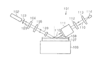
従来、液体あるいは固体薄膜の分布観測には、図6に示すような走査型エリプソメータ(エリプソメトリー装置)が広く用いられてきた(例えば特許文献1)。このようなエリプソメータ101は、光源102から照射された光コリメーションレンズ103で平行光とされ、偏光子104で直線偏光とされ、λ/4板105で円偏光又は楕円偏光に変換され、試料走査用ステージ106上に載置された基板107上の薄膜108(液体膜又は固体膜)に照明光109を照射する。試料の薄膜108は、試料走査用ステージ106により順次走査されていく。この照明光109は薄膜108で反射し、その反射光110は、対物レンズ111を通過して検光子112を通って結像レンズ113により光検出装置114に入射して測定される。
Conventionally, a scanning ellipsometer (ellipsometer) as shown in FIG. 6 has been widely used to observe the distribution of a liquid or solid thin film (for example, Patent Document 1). Such an
エリプソメトリー装置では、試料と空気などの媒質界面で、光がある入射角で反射したときに、入射平面に平行な偏光成分(p偏光)、垂直な偏光成分(s偏光)についての複素振幅反射率が、試料薄膜の屈折率を決める膜厚に依存するので、薄膜の膜厚分布に対応した光反射強度像が得られ、試料各点における膜厚分布を観測できる。 In an ellipsometry apparatus, when light is reflected at a certain incident angle at the interface between a sample and air or the like, a complex amplitude reflection of a polarized light component parallel to the incident plane (p-polarized light) and a vertical polarized light component (s-polarized light). Since the rate depends on the film thickness that determines the refractive index of the sample thin film, a light reflection intensity image corresponding to the film thickness distribution of the thin film can be obtained, and the film thickness distribution at each point of the sample can be observed.
ところで、エリプソメトリー装置は、試料(屈折率ns)と空気(屈折率no)の界面で光が反射した場合、光の入射角をθB=tan−1(ns/no)で求められるブリュースター角θB付近に設定して使用される。この設定では、p偏光に対する反射率は最小値を取るので、p偏光とs偏光の複素振幅反射率の差が最も大きくなり、最も良好なコントラストを有する膜分布像が得られる。このブリュースター角θBは、一般に液体や固体では60〜70度付近にあるので、エリプソメトリー顕微鏡では、p偏光に対する反射率が最小となるように法線から60〜70度程度の比較的大きな入射角で試料に照明光を斜めに照射し、その入射角と同程度の反射角で反射する反射光を斜め方向から観測する必要があった。このため、エリプソメトリー装置においては、図6に示すような斜め照明系を採用し、結像系の対物レンズ111の光軸を、薄膜の試料面に対して斜めに配置する必要があった。
By the way, in the ellipsometry apparatus, when light is reflected at the interface between the sample (refractive index ns) and air (refractive index no), the Brewster angle in which the incident angle of light is obtained by θB = tan −1 (ns / no). It is set and used near θB. In this setting, since the reflectance for p-polarized light takes the minimum value, the difference between the complex-amplitude reflectances of p-polarized light and s-polarized light becomes the largest, and a film distribution image having the best contrast can be obtained. Since the Brewster angle θB is generally in the vicinity of 60 to 70 degrees for liquids and solids, in an ellipsometry microscope, a relatively large incident of about 60 to 70 degrees from the normal so as to minimize the reflectance for p-polarized light. It was necessary to irradiate the sample with illumination light at an angle and to observe the reflected light reflected at an angle of reflection similar to the incident angle from an oblique direction. Therefore, in the ellipsometry apparatus, it is necessary to employ an oblique illumination system as shown in FIG. 6 and to arrange the optical axis of the
このように試料を斜めから観測する構成であると、焦点深度の関係から狭い視野しか得られないという問題があった。このように、対物レンズ111の光軸を試料面に対して斜めに配置する観測系では、実用的に有用な視野が確保できず、好適な高倍率観測が困難であった。
When the sample is observed obliquely in this way, there is a problem that only a narrow field of view can be obtained due to the depth of focus. Thus, in the observation system in which the optical axis of the
加えて、一般に高倍率の対物レンズは作動距離が小さい。このため、対物レンズ111の光軸を試料面に対して斜めに配置する観測系では、対物レンズと試料基板の接触を避けるために、試料をレンズから遠ざけて低倍率で観察するか、p偏光に対する反射率が最小となる条件から外れた入射角で光を照射し、低コントラストで観察するかしなければならなかった。
In addition, a high-power objective lens generally has a small working distance. For this reason, in an observation system in which the optical axis of the
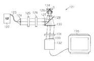
この種の問題を解消するため、特許文献1には、図7に示すエリプソメトリー顕微鏡(エリプソメトリー装置)が提案されていた。図7に示すエリプソメトリー顕微鏡121は、斜め照明系は、光源122、光ファイバ123、コリメートレンズ124、偏光子125、位相補償子126、集光レンズ127、ビームスプリッタ128等から構成されていた。また、結像系は、対物レンズ129、結像レンズ130、検光子131、撮像装置132の検出面133で構成されていた。そして、斜め照明系と結像系とが同じ対物レンズ129を共用し、対物レンズ129の光軸を試料Sの試料面134に対して垂直に配置していた。
In order to solve this kind of problem,
光源122から光ファイバ123を通じて発光した拡散光はコリメートレンズ124により平行光とされ、偏光子125により直線偏光とされ、さらにλ/4板からなる位相補償子126により楕円偏光(円偏光を含む)とされる。
The diffused light emitted from the
集光レンズ127で集光された楕円偏光よりなる照明光は、ビームスプリッタ128で屈曲し、対物レンズ129の光軸からシフトした位置を通って平行光として試料Sを照射する。試料Sで正反射した反射光R1は、対物レンズ129にその光軸に対して入射時と異なる側へシフトした位置を通り、ビームスプリッタ128を透過し、結像レンズ130及び検光子131を通過した後、撮像装置132の検出面133に照射される。そして、撮像装置132により撮像された試料の像がモニタ135に映し出される。
Illumination light composed of elliptically polarized light collected by the
このように対物レンズ129の光軸が試料Sの試料面134に垂直に配置されるので、視野の狭小化の問題は解消される。しかも、試料面に対する光の入射角をブリュースター角θB付近に設定できるので、微小な膜厚差を有する膜分布を高感度かつ高コントラスト(高分解能)で観察できる。
Thus, since the optical axis of the objective lens 129 is arranged perpendicular to the
ところで、エリプソメトリー顕微鏡は光学的観測法であるため、非接触観測が可能で、試料に接触する必要がない。そのため、図6に示す構成の装置であれば、試料面に対して法線方向観察側の位置に、他の計測あるいは操作手段のための作業空間を確保でき、他の計測手段あるいは操作手段との組合せにより多くの機能を実現できる。その一例として、走査型プローブ顕微鏡とエリプソメトリー顕微鏡とを組み合わせた顕微鏡が挙げられる。この顕微鏡では、エリプソメトリー顕微鏡の高速な画像取得速度を活かして、試料面の広い領域を観察し、そのうちの注目する狭い領域をプローブ顕微鏡で詳細に観察することにより、効率的かつ的確な観測ができる。また、粘弾性を有する薄膜にプローブ等の操作手段を摺動させて力学的な刺激を与える操作を行い、その応答の様子を動的観察したい場合もある。 By the way, since the ellipsometry microscope is an optical observation method, non-contact observation is possible and it is not necessary to contact the sample. Therefore, with the apparatus having the configuration shown in FIG. 6, a working space for other measurement or operation means can be secured at a position on the normal direction observation side with respect to the sample surface. Many functions can be realized by the combination. One example is a microscope that combines a scanning probe microscope and an ellipsometry microscope. In this microscope, taking advantage of the high-speed image acquisition speed of an ellipsometry microscope, a wide area of the sample surface is observed, and a narrow area of interest is observed in detail with a probe microscope, enabling efficient and accurate observation. it can. In some cases, it is desired to dynamically observe the state of the response by performing an operation of applying a mechanical stimulus by sliding an operating means such as a probe on a thin film having viscoelasticity.
しかしながら、特許文献1に記載された図7に示すエリプソメトリー顕微鏡では、試料面に対して垂直に対物レンズが配置されていたので、この対物レンズが妨げとなって、試料面に接触する走査用プローブ等の計測手段や摺動用プローブ等の操作手段などの作業空間が確保できないという問題があった。
However, in the ellipsometry microscope shown in FIG. 7 described in
本発明は、このような従来の技術に存在する問題点に着目してなされたものであり、その目的は、物体の微小構造を高コントラストかつ高倍率で観察できるうえ、物体面に対して法線方向観察側の位置に、物体面に接触又は近接して用いられる計測手段や操作手段などのための作業空間を確保できるエリプソメトリー装置を提供することにある。 The present invention has been made paying attention to such problems existing in the prior art, and its purpose is to enable observation of the microstructure of an object with high contrast and high magnification, and to apply a method to the object surface. An object of the present invention is to provide an ellipsometry apparatus capable of ensuring a work space for measuring means, operating means, etc. used in contact with or close to an object surface at a position on the line direction observation side.
上記課題を解決するため、請求項1に記載の本発明は、偏光解析法を用いて観察対象の物体の像を拡大して観察可能なエリプソメトリー装置であって、光源の光路上に偏光子と位相補償子とを有し、当該偏光子及び位相補償子を通った平行光を前記物体に斜めに照射する斜め照明系と、物体からの反射光を入射して物体像を拡大して結像させる結像系と、前記結像系における前記反射光の光路の途中に設けられた検光子と、前記結像系により結像された像を撮像する撮像素子と、を備え、前記結像系は、前記物体からの反射光を入射して第1の倍率で物体像を結像させる少なくとも一つのレンズを含む1次結像系と、前記1次結像系が結像した物体像を前記第1の倍率より大きな第2の倍率で拡大する少なくとも一つのレンズを含む2次結像系と、を備えたことを要旨とする。
In order to solve the above-mentioned problem, the present invention according to
この構成によれば、結像系が、物体からの反射光を入射して第1の倍率で物体像を結像させる1次結像系と、第1の倍率より大きな第2の倍率で物体像を拡大する2次結像系との複数段で構成されるので、物体からの反射光を入射する1次結像系における第1の倍率を相対的に小さく設定できる。このため、第1の倍率に依存する、1次結像系の光軸とその結像面とのなす角度を、相対的に大きくすることが可能になる。そして、1次結像系の光軸に対して相対的に大きな角度をなす結像面上に結像された物体像が、2次結像系により第2の倍率で拡大される。従って、物体の微小構造を高コントラストかつ高倍率で観察できるうえ、物体面に対して法線方向観察側の位置に、物体面に接触又は近接して用いられる計測手段や操作手段などのための作業空間を確保できる。 According to this configuration, the imaging system includes a primary imaging system that forms an object image at a first magnification by incident reflected light from the object, and an object at a second magnification that is greater than the first magnification. Since it is composed of a plurality of stages with the secondary imaging system for enlarging the image, the first magnification in the primary imaging system that receives the reflected light from the object can be set relatively small. For this reason, it is possible to relatively increase the angle between the optical axis of the primary imaging system and its imaging plane, which depends on the first magnification. Then, the object image formed on the imaging plane that forms a relatively large angle with respect to the optical axis of the primary imaging system is magnified at the second magnification by the secondary imaging system. Therefore, it is possible to observe the microstructure of the object with high contrast and high magnification, as well as for measuring means and operating means used in contact with or close to the object surface at a position on the normal direction observation side with respect to the object surface. Work space can be secured.
請求項2に記載の発明では、請求項1に記載のエリプソメトリー装置において、前記2次結像系の光軸を、前記1次結像系の結像面と略垂直になるように配置するとともに、前記2次結像系の結像面が前記撮像素子の検出面と略重なるように前記撮像素子を配置したことを要旨とする。 According to a second aspect of the present invention, in the ellipsometry apparatus according to the first aspect, the optical axis of the secondary imaging system is arranged so as to be substantially perpendicular to the imaging plane of the primary imaging system. In addition, the gist of the present invention is that the imaging element is arranged so that the imaging plane of the secondary imaging system substantially overlaps the detection plane of the imaging element.
この構成によれば、1次結像系のように物体面と1次結像系の光軸とのなす角度が鋭角である場合は、2次結像系のレンズへの光の反射率を低減する必要から、1次結像系に設定できる倍率に制約がある。これに対して、2次結像系の光軸は1次結像系の結像面と略垂直になるように配置されているので、その種の制約がなくなり、2次結像系を高い倍率に設定できる。そして、2次結像系の結像面が検出面と略重なるように撮像素子が配置されているので、撮像素子により、高コントラストかつ高倍率でしかも輝度分布がより均一な像を撮像できる。 According to this configuration, when the angle between the object plane and the optical axis of the primary imaging system is an acute angle as in the primary imaging system, the reflectance of light to the lens of the secondary imaging system is increased. There is a limit to the magnification that can be set in the primary imaging system because of the need to reduce it. On the other hand, since the optical axis of the secondary imaging system is arranged so as to be substantially perpendicular to the imaging surface of the primary imaging system, there is no such restriction and the secondary imaging system is high. Can be set to magnification. Since the imaging device is arranged so that the imaging surface of the secondary imaging system substantially overlaps the detection surface, the imaging device can capture an image with high contrast, high magnification, and more uniform luminance distribution.
請求項3に記載の発明では、請求項1又は2に記載のエリプソメトリー装置において、前記1次結像系の光軸と物体面とのなす角度θo、前記光軸と前記1次結像系の結像面とのなす角度θ1とした場合、前記1次結像系の倍率M1は、M1=tanθo/tanθ1において、角度θ1を20度以上としうる値に設定されていることを要旨とする。 According to a third aspect of the present invention, in the ellipsometry apparatus according to the first or second aspect, an angle θo between the optical axis of the primary imaging system and the object plane, the optical axis and the primary imaging system. The angle M1 of the primary imaging system is set to a value that allows the angle θ1 to be 20 degrees or more when M1 = tan θo / tan θ1. .
この構成によれば、1次結像系は、角度θ1を20度以上としうる倍率M1(=tanθo/tanθ1)値に設定されているので、角度θ1を20度以上の比較的大きな値に設定することで、1次結像系から2次結像系のレンズへ入射する光の反射率を低減できる。このため、2次結像系によって撮像素子に明るい像を結像できる。 According to this configuration, since the primary imaging system is set to a magnification M1 (= tan θo / tan θ1) that can make the angle θ1 20 degrees or more, the angle θ1 is set to a relatively large value of 20 degrees or more. By doing so, it is possible to reduce the reflectance of light incident on the lens of the secondary imaging system from the primary imaging system. Therefore, a bright image can be formed on the image sensor by the secondary imaging system.
請求項4に記載の発明では、請求項1乃至3のいずれか一項に記載のエリプソメトリー装置において、前記1次結像系の倍率M1は、0.3〜3倍の範囲内の値に設定されていることを要旨とする。 According to a fourth aspect of the present invention, in the ellipsometry apparatus according to any one of the first to third aspects, the magnification M1 of the primary imaging system is a value within a range of 0.3 to 3 times. The gist is that it is set.
この構成によれば、倍率M1が0.3〜3倍の範囲内の値に設定されているので、1次結像系の光軸と1次結像系の結像面とのなす角度を比較的大きな値に設定することができる。よって、1次結像系から2次結像系のレンズへ入射する光の反射率を低減して、2次結像系により撮像素子に明るい像を結像できる。 According to this configuration, since the magnification M1 is set to a value within the range of 0.3 to 3 times, the angle formed between the optical axis of the primary imaging system and the imaging plane of the primary imaging system is set. It can be set to a relatively large value. Therefore, the reflectance of light incident on the lens of the secondary imaging system from the primary imaging system can be reduced, and a bright image can be formed on the image sensor by the secondary imaging system.
請求項5に記載の発明では、請求項3又は4に記載のエリプソメトリー装置において、前記1次結像系の光軸と物体面とのなす角度θoと、前記光軸と前記1次結像系の結像面とのなす角度θ1は、θo≧θ1を満たし、M1=tanθo/tanθ1により決まる前記1次結像系の倍率M1は1倍以上に設定されていることを要旨とする。 According to a fifth aspect of the present invention, in the ellipsometry apparatus according to the third or fourth aspect, an angle θo between the optical axis of the primary imaging system and the object plane, the optical axis and the primary imaging. The angle θ1 formed with the imaging plane of the system satisfies θo ≧ θ1, and the magnification M1 of the primary imaging system determined by M1 = tan θo / tan θ1 is set to 1 or more.
この構成によれば、例えば1次結像系の倍率が1倍未満であるとすると、2次結像系の倍率を高くしても、結像系全体の倍率が2次結像系と同じ倍率も得られなくなるが、1次結像系の倍率が1倍以上なので、結像系全体の倍率として2次結像系の倍率以上の倍率を得ることができる。 According to this configuration, for example, if the magnification of the primary imaging system is less than 1, even if the magnification of the secondary imaging system is increased, the magnification of the entire imaging system is the same as that of the secondary imaging system. Although the magnification cannot be obtained, since the magnification of the primary imaging system is 1 or more, a magnification higher than that of the secondary imaging system can be obtained as the magnification of the entire imaging system.
請求項6に記載の発明では、請求項1乃至5のいずれか一項に記載のエリプソメトリー装置において、物体のp偏光に対する反射率が略最小となるような入射角で前記物体に照明光を照射して観察又は膜厚分布測定が行われる構成であり、前記1次結像系の光軸は、物体面からの反射光の光軸が想定される最小反射角をとるときの当該光軸に対して前記物体面から離れる方向へひねり角度Δθだけ傾けて配置されていることを要旨とする。 According to a sixth aspect of the present invention, in the ellipsometry apparatus according to any one of the first to fifth aspects, the illumination light is applied to the object at an incident angle such that the reflectance of the object with respect to p-polarized light is substantially minimized. Observation or film thickness distribution measurement is performed by irradiation, and the optical axis of the primary imaging system is the optical axis when the optical axis of the reflected light from the object plane assumes a minimum reflection angle. The gist of the present invention is that they are inclined by a twist angle Δθ in a direction away from the object plane.
この構成によれば、1次結像系の光軸と物体面とのなす角度θoを大きく確保できるので、角度θ1を大きくした割に、M1=tanθo/tanθ1で表される1次結像系の倍率M1がさほど小さくならずに済む。 According to this configuration, a large angle θo formed by the optical axis of the primary imaging system and the object plane can be secured, so that the primary imaging system represented by M1 = tan θo / tan θ1 for a large angle θ1. The magnification M1 is not so small.
本発明によれば、物体の微小構造を高コントラストかつ高倍率で観察できるうえ、物体面に対して法線方向観察側の位置に、物体面に接触又は近接して用いられる計測手段や操作手段などのための作業空間を確保できるという効果が得られる。 According to the present invention, the microstructure of an object can be observed with high contrast and high magnification, and the measuring means and operating means used in contact with or in proximity to the object surface at a position on the normal direction observation side with respect to the object surface The effect that the work space for such as can be secured is obtained.
(第1実施形態)
以下、本発明をエリプソメトリー顕微鏡に具体化した第1実施形態を、図1〜図3を用いて説明する。本実施形態では、エリプソメトリー顕微鏡は複合型顕微鏡の一部を構成する。
(First embodiment)
Hereinafter, a first embodiment in which the present invention is embodied in an ellipsometry microscope will be described with reference to FIGS. In the present embodiment, the ellipsometry microscope constitutes a part of the composite microscope.
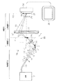
図1は、複合型顕微鏡におけるエリプソメトリー顕微鏡の全体構成を示す模式図である。図1に示すように、エリプソメトリー装置としてのエリプソメトリー顕微鏡1は、走査型プローブ顕微鏡70(Scanning Probe Microscope(SPM))と組み合わせて複合型顕微鏡80を構成している。この複合型顕微鏡80では、エリプソメトリー顕微鏡1により試料Sの基板2上に形成された薄膜3を比較的広い視野で低倍率で観察し、そのうち特に微細構造を観察したい注目箇所を走査型プローブ顕微鏡70により高倍率で観察できるようになっている。なお、本実施形態では、走査型プローブ顕微鏡70の一例として、原子間力顕微鏡(Atomic Force Microscope(AFM))を採用している。
FIG. 1 is a schematic diagram showing an overall configuration of an ellipsometry microscope in a composite microscope. As shown in FIG. 1, an
図1に示すように、エリプソメトリー顕微鏡1は、斜め照明系4と結像系5とを備えている。本実施形態の結像系5は、1次結像系10と2次結像系11とを有している。以下、斜め照明系4、結像系5の順番に説明する。
As shown in FIG. 1, the
図1に示すように、斜め照明系4は、光源12、光ファイバ13、コリメートレンズ14、偏光子15、位相補償子16、レンズ17から構成されている。光源12で発生させた照明光は、光ファイバ13により導かれて所定位置で略点光源として拡散光である照明光L1として発光し、コリメートレンズ14により平行光である照明光L2とされる。この照明光L2は、偏光子15により、直線偏光とされた照明光L3となる。そして、λ/4板からなる位相補償子16により、楕円偏光(円偏光を含む)である照明光L4とされる。この照明光L4は、コリメートレンズ17を通って平行光として、試料Sの試料面に照射される。
As shown in FIG. 1, the oblique illumination system 4 includes a
試料Sの基板2上に形成された薄膜3は、液体膜あるいは固体膜からなる。また、試料Sが載置された不図示のステージが傾動可能に構成されるか、斜め照明系4の光照射角が変更可能に構成されることで、エリプソメトリー顕微鏡1では、試料Sに対する照射光の入射角の調整が可能となっている。この入射角は、薄膜3の材質から決まる屈折率に応じて調整され、通常、p偏光に対する反射率が最小値を取るように、ブリュースター角θB=tan−1(ns/no)(但し、nsは試料の屈折率ns、noは空気の屈折率)付近の値に設定される。例えば、試料Sをシリコン基板とした場合、ブリュースター角θBは約74度である。また、試料Sに金属などの光吸収する材質を含む場合、p偏光に対する反射率が完全に0とはならないが、一般に入射角60から70度付近で、p偏光に対する反射率は最小値を取る。このため、通常60〜80度の比較的大きな入射角で照明光L4は試料Sの試料面に照射される。
The
次に、結像系5について説明する。図1に示すように、結像系5は、1次結像系10と2次結像系11とを有している。1次結像系10は、1個の対物レンズ21を有している。また、2次結像系11は、1個の結像レンズ22を有している。結像レンズ22には、2次結像用の対物レンズが用いられている。
Next, the
ここで、1次結像系10とは、図1に示すように、試料Sからの反射光が最初に入射する対物レンズ21を含む結像系であり、その倍率M1(第1の倍率)は比較的低倍率である。また、2次結像系11とは、1次結像系10の結像面(以下、「1次結像面P1」という)に結像された物体像を所望の倍率に拡大して、その結像面(以下、「2次結像面P2」という)と一致する撮像素子24の検出面25にその拡大物体像を結像させる結像系であり、その倍率M2(第2の倍率)は比較的高倍率である。1次結像系10と2次結像系11は、それぞれ少なくとも1個の結像用のレンズを含み、特に本実施形態は、1次結像系10と2次結像系11がそれぞれ結像用のレンズを1個ずつ備えた例となる。
Here, as shown in FIG. 1, the
図1に示すように、試料Sを照射した照明光L4(以下、「入射光L4」とも称す)は、試料Sで反射して反射光である反射光R1となり、対物レンズ21に入射する。そして、この反射光R1(但し、図1では入射光L4の光軸での反射光(散乱光)の光路のみ図示)は、対物レンズ21により一旦集光されてから再び拡散する反射光R2となる。この対物レンズ21を保持する鏡筒26は、結像系5の絞りとしても機能する。この拡散する反射光R2は結像レンズ22の鏡筒27内の範囲に入射して、結像レンズ22により集光されて反射光R3とされ、さらに検光子23を通過した反射光R4は撮像素子24の検出面25に照射される。撮像素子24の検出面25に照射された反射光R4は電気信号に変換され、液晶ディスプレイからなるモニタ28に、拡大された物体像(薄膜3の拡大像)が映し出される。
次に、本エリプソメトリー顕微鏡の各構成要素について、図1〜図3を用いて詳細に説明する。
(光源)
As shown in FIG. 1, illumination light L <b> 4 (hereinafter also referred to as “incident light L <b> 4”) irradiated on the sample S is reflected by the sample S to become reflected light R <b> 1 that is reflected light, and enters the
Next, each component of the present ellipsometry microscope will be described in detail with reference to FIGS.
(light source)
光源12は、SLD(Super Luminescent Diode)により構成されている。仮に光源に、He−NeレーザーあるいはLD(Laser Diode)のように可干渉距離(コヒーレンス長)の長いレーザーなどを光源に用いた場合、装置光学系を構成する光学素子で光の一部が反射することにより、光干渉が発生し、干渉縞像が現れてしまう。例えば、λ/4板からなる位相補償子16で反射され後方に進んだ光が、さらに偏光子15により反射され再度前方に進んで検出面に到達したとする。このとき、これらの反射を経ず直進した光で検出面に同時に達する光も存在する。これらの反射を経た光と反射を経ず直進した光とは異なった光路長を進んで来るので、位相が異なり検出面で光干渉を生ずる。すなわち、このとき検出面には干渉縞像が生じ、薄膜像に重畳して雑音像が生ずることになる。ここで、一般に、その可干渉距離よりも大きな光路差を有する光同士は干渉しない。そこで、その可干渉距離が、装置を構成する光学素子間距離よりも十分小さい光源を用いると、干渉縞像の発生を抑えることができる。この光源12では、可干渉距離の短いレーザーSLDにより構成されている。装置光学系を構成する光学素子間距離は、1mmから10cmのオーダーであるのに対して、SLDの可干渉距離は、10μmのオーダーであり十分小さい。SLDに代えて、ファイバレーザーやハロゲンランプを用いた白色光源や、ASE(Amplified Spontaneous Emission)、LED(Light Emitting Diode 発光ダイオード)等により光源12を構成してもよい。
また、図1では模式的に単一のコリメートレンズ14,17を描いたが、正確な平行光を生成する各種光学素子や光学器具等が用いられる。
(偏光子)
The
In FIG. 1, the
(Polarizer)
偏光子15は、周知の偏光板を用い照明光L2を直線偏光にすることができ、照明光L2の光軸に対して回転可能に設けられ、直線偏光の方向を90度の範囲で変更できる。
(位相補償子)
The polarizer 15 can convert the illumination light L2 into a linearly polarized light using a known polarizing plate, is provided so as to be rotatable with respect to the optical axis of the illumination light L2, and can change the direction of the linearly polarized light within a range of 90 degrees. .
(Phase compensator)
位相補償子(コンペンセンター)16は、直線偏光を楕円偏光に変換する。本実施形態の位相補償子16は、λ/4板(1/4波長板)からなる。光源によるが、本実施形態では、広域のスペクトルを有するSLD光源を用いているため、無着色のアクロマティックリターダを用いる。なお、理想的な位相補償子は、リターデーションが正確に90度(又は1/4波長)である光学的な位相遅延器であるが、正確なリターデーションが光軸や波長によって変わってしまうために用いることが難しい。そのため、本実施形態では、回転する偏光子15と回転する位相補償子16の組合せとなっており、偏光していない光をどのような楕円偏光にも変換できる。
(撮像素子)
The phase compensator (compensation center) 16 converts linearly polarized light into elliptically polarized light. The
(Image sensor)
撮像素子24は、電荷結合素子(Charge Coupled Device(CCD))をマトリクス状に整列させたアレイ状の素子である。なお、撮像素子は、CCDに限定されるものではなく、CMOS(相補性金属酸化膜半導体)イメージセンサを用いた構成としてもよい。さらに冷却CCDカメラも熱ノイズが少なく好ましい。
(結像系)
The
(Imaging system)
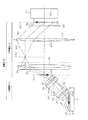
次に、本実施形態における特徴的な構成である1次結像系10と2次結像系11について説明する。図2は、1次結像系と2次結像系に係る部分の模式側面図である。図2に示すように、1次結像系10を構成する対物レンズ21は、その光軸AX1と試料面SP(換言すればステージの試料載置面)とのなす角度θoが、反射光R1の光軸AX2と試料面SPとのなす角度である反射角θrefよりも大きくなるように、光軸AX1を光軸AX2に対して少し傾けた状態に配置されている。つまり、対物レンズ21の光軸AX1を反射光R1の光軸AX2に対して角度Δθ(=θo−θref)だけ試料面SPから離れる側へ傾ける「ひねり」を加えている。なお、以下、角度Δθをひねり角度と呼ぶ。
Next, the
対物レンズ21を通って集光する反射光R2は、結像レンズ22に至る手前の空間上で結像する。つまり、この対物レンズ21の結像面(1次結像面P1)が、対物レンズ21と結像レンズ22との間の空間上に形成される。そして、結像レンズ22はその光軸AX3が1次結像面P1に対して垂直(図2におけるθ2=90°)になるように配置されている。撮像素子24はその検出面25の中心軸AX4が結像レンズ22の光軸AX3と一致するように配置されている。
The reflected light R2 collected through the
結像レンズ22の焦点距離をf1とおくと、結像レンズ22は、その主平面が1次結像面P1に対してその法線方向(光軸AX3方向)後側(図2における右側)へ、距離(x1+f1)だけ離れて位置するように配置されている。また、撮像素子24は、その検出面25が結像レンズ22の主平面に対してその法線方向(光軸AX3方向)後側へ、距離(f1+x2)だけ離れて位置するように配置されている。なお、x1,x2には、x1・x2=f12の関係がある。
When the focal length of the
結像レンズ22は、1次結像面P1に結像された物体像を拡大して撮像素子24の検出面25上に結像させる機能を有している。このため、撮像素子24は、その検出面25が2次結像面P2と一致するように配置されている。つまり、図2における距離x2は、結像レンズ22の主平面と2次結像面P2との間の距離から、結像レンズ22の焦点距離f1を差し引いた距離に設定されている。
The
本実施形態では、1次結像系10を構成する対物レンズ21の倍率M1を、2次結像系11を構成する結像レンズ22の倍率M2よりも小さく設定している(M1<M2)。このように設定している理由は以下の通りである。
対物レンズ21の光軸AX1と1次結像面P1とのなす角度をθ1とおくと、対物レンズ21の倍率M1と角度θo,θ1との間には、以下の関係が成立する。
tanθ1/tanθo=1/M1 …(1)
In this embodiment, the magnification M1 of the
When the angle formed by the optical axis AX1 of the
tanθ1 / tanθo = 1 / M1 (1)
この式(1)から、対物レンズ21の倍率M1を大きくするほど、角度θoに対して角度θ1は小さくなる。角度θ1が小さくなるに連れて、1次結像面P1は、光軸AX1との交点を中心に、図2における時計方向へ徐々に傾く。この角度θ1は、結像レンズ22の主平面と光軸AX1とのなす角度に等しいので、角度θ1が小さくなるほど、結像レンズ22に対する反射光R2の入射角(結像レンズ22の主平面と反射光R2とのなす角度)が大きくなる。この反射光R2の入射角が大きくなると、結像レンズ22における光の反射率が増えてしまう。
From this equation (1), as the magnification M1 of the
例えば角度θoを30度とした場合、倍率M1を100倍にしてしまうと、式(1)から、角度θ1=0.3度という結像レンズ22の主平面とほぼ平行な反射光R2となってしまう。この場合、結像レンズ22の鏡筒26に反射光R2が遮られて反射光R2が結像レンズ22にさえ入射できなくなる。また、仮に反射光R2が鏡筒26に遮られることなく結像レンズ22に入射できても、かなり大きな入射角になるため、結像レンズ22の表面での反射光R2の反射率が、s偏光に対して約0.98、p偏光に対して約0.96とかなり増加する。この場合、検出面25に結像される像が著しく暗くなってしまう。
For example, when the angle θo is set to 30 degrees, if the magnification M1 is increased to 100 times, the reflected light R2 that is substantially parallel to the main plane of the
このため、本実施形態では、この種の反射率の増加を回避すべく、対物レンズ21の倍率M1を相対的に小さく設定し、倍率M1と式(1)とから決まる角度θ1を、相対的に大きな値に設定している。反射光R2の反射率を許容範囲内に小さく抑えるためには、角度θ1は例えば20度以上に設定することが好ましい。本実施形態では、角度θ1を、一例として45度に設定している。
For this reason, in this embodiment, in order to avoid this kind of increase in reflectance, the magnification M1 of the
例えば入射光L4の入射角がブリュースター角θB付近の60〜80度である場合、試料面SPで正反射した反射光R1の光軸AX2の反射角θrefは60〜80度となる。このとき、想定される正反射光R1の最小反射角θrefmin(=60度)のときの光軸AX2よりも、対物レンズ21の光軸AX1(つまり1次結像系10の光軸)を、ひねり角度Δθ(>0)だけ試料面SPから離れる方向(図2における反時計方向)へ傾けて配置している。このため、試料面SPに対する入射光L4を想定される入射角(60〜80度)で使用する場合、対物レンズ21の光軸AX1が常に反射光R1の光軸AX2よりも試料面SPから離れる方向へ傾いた状態に保持され、反射角θrefより大きな角度θoを確保できる。このようにひねり角度Δθを加えた場合、試料面SPからの反射光R1は、図2,図3に示すように、対物レンズ21の中心から試料S側へシフトした位置を光軸が通るように対物レンズ21に入射する。
For example, when the incident angle of the incident light L4 is 60 to 80 degrees near the Brewster angle θB, the reflection angle θref of the optical axis AX2 of the reflected light R1 specularly reflected by the sample surface SP is 60 to 80 degrees. At this time, the optical axis AX1 of the objective lens 21 (that is, the optical axis of the primary imaging system 10) is set to be larger than the optical axis AX2 at the assumed minimum reflection angle θrefmin (= 60 degrees) of the regular reflection light R1. They are arranged so as to be inclined by a twist angle Δθ (> 0) in a direction away from the sample surface SP (counterclockwise in FIG. 2). For this reason, when the incident light L4 with respect to the sample surface SP is used at an assumed incident angle (60 to 80 degrees), the optical axis AX1 of the
本実施形態では、一例として、ひねり角度Δθを15度に設定し、角度θo(=90°−θre fmin+Δθ)を45度に設定している。この場合、角度θo,θ1が共に45度になる倍率M1は、式(1)からM1=tanθo/tanθ1であるので、1倍である。このため、本実施形態では、倍率M1が1倍の対物レンズ21を用いている。もちろん、倍率M1は1倍に限定されず、角度θoと式(1)式の関係とから、角度θ1を比較的大きな値(例えば20度以上)にできる倍率M1を採用できる。さらに角度θ1は、20度以上に限られず、反射光R2が鏡筒27に遮らずに結像レンズ22に入射でき、かつ結像レンズ22における反射光R2の反射率をある程度小さく抑えられれば、例えば20度未満でもよい。
In this embodiment, as an example, the twist angle Δθ is set to 15 degrees, and the angle θo (= 90 ° −θrefmin + Δθ) is set to 45 degrees. In this case, the magnification M1 at which the angles θo and θ1 are both 45 degrees is 1 since M1 = tan θo / tan θ1 from the equation (1). For this reason, in the present embodiment, the
また、角度θoは、20〜60度の範囲が好ましい。このとき、ひねり角度Δθは、必ずしも設定する必要はなく、例えば角度θoを20≦θo<30の範囲に設定する場合は、ひねり角度Δθは0度でもよい。また、角度θoを30≦θo≦60の範囲に設定する場合は、ひねり角度Δθを、0<Δθ≦30の範囲で設定すればよい。そして、角度θoが20〜60度の範囲内の値をとるときに、角度θ1が、20〜70度の範囲、好ましくは30〜60度の範囲で確保されるような倍率M1(=tanθo/tanθ1)に設定することが望ましい。 The angle θo is preferably in the range of 20 to 60 degrees. At this time, the twist angle Δθ is not necessarily set. For example, when the angle θo is set in a range of 20 ≦ θo <30, the twist angle Δθ may be 0 degree. When the angle θo is set in the range of 30 ≦ θo ≦ 60, the twist angle Δθ may be set in the range of 0 <Δθ ≦ 30. Then, when the angle θo takes a value within the range of 20 to 60 degrees, the magnification M1 (= tan θo /) that ensures the angle θ1 within the range of 20 to 70 degrees, preferably within the range of 30 to 60 degrees. It is desirable to set to tan θ1).
倍率M1は、例えば0.1〜5倍、好ましくは0.3〜3倍の範囲がよい。もちろん、倍率M1は、この範囲に限定されず、0.1倍未満(0<M1<0.1)としたり、5倍を超えてもよい。但し、対物レンズ21の倍率M1を1倍未満の値にすると、エリプソメトリー顕微鏡1に所望の倍率Mを確保するために、結像レンズ22の倍率M2を高くする必要があり、倍率M2にも限界があるので、倍率M1をあまり小さくし過ぎることは好ましくない。この点から、倍率M1は0.8倍以上、特に1倍以上が好ましい。
The magnification M1 is, for example, in the range of 0.1 to 5 times, preferably 0.3 to 3 times. Of course, the magnification M1 is not limited to this range, and may be less than 0.1 times (0 <M1 <0.1) or more than 5 times. However, if the magnification M1 of the
また、倍率M1は、M1=tanθo/tanθ1から決まるため、倍率M1を1倍以上にするためには、θo≧θ1を満たす必要がある。このとき、ひねり角度Δθを加えて角度θoを大きくすることにより、1倍以上の倍率M1を確保しうる角度θ1の上限を大きくすることができる。そして、本実施形態では、一例として、1倍以上の倍率M1を確保しうる角度θ1の上限を採用している(θo=θ1)。もちろん、倍率M1が1倍未満の場合も、ひねり角度Δθを加えて角度θoを設定することにより、角度θ1を大きくした割に、倍率M1が小さくなりにくい。よって、角度θoは、特に30度以上に設定することが望ましい。
Further, since the magnification M1 is determined from M1 = tan θo / tan θ1, it is necessary to satisfy θo ≧ θ1 in order to make the
図2に示すように、2次結像系11において、結像レンズ22の主平面と1次結像面P1との距離は、x1+f1で示され、その主平面と撮像素子24の検出面25との距離は、f1+x2で示される。つまり、x1は、結像レンズ22の主平面と1次結像面P1との距離から結像レンズ22の焦点距離f1(前側焦点距離)を差し引いた値であり、x2は、結像レンズ22の主面と検出面25との距離から結像レンズ22の焦点距離f1(後側焦点距離)を差し引いた値である。
As shown in FIG. 2, in the
ここで、1次結像面P1上に結像される1次物体像と、検出面25(2次結像面P2)上に結像される2次物体像との像の高さの比、すなわち、2次結像系11の像倍率M2は、f1を結像レンズ22の焦点距離、x1を図2に与えた距離として、以下の式で与えられる。
M2=f1/x1 …(2)
Here, the ratio of the heights of the primary object image formed on the primary imaging plane P1 and the secondary object image formed on the detection plane 25 (secondary imaging plane P2). That is, the image magnification M2 of the
M2 = f1 / x1 (2)
この式(2)から、像倍率M2は、角度θ1に依存することなく設定でき、高倍率観測が可能になる。すなわち、結像レンズ22の焦点距離f1と距離x1とにより、2次結像系11の像倍率M2を設定できる。
From this equation (2), the image magnification M2 can be set without depending on the angle θ1, and high magnification observation becomes possible. That is, the image magnification M2 of the
結像レンズ22には、前述のように、対物レンズ21の倍率M1より大きな倍率(例えば100倍)の対物レンズが使用されている。エリプソメトリー顕微鏡1の倍率Mは、1次結像系10の倍率M1と2次結像系11の倍率M2とを用いて、M=M1×M2で表される。そして、本実施形態では、倍率M2(=M/M1)が得られるように、結像レンズ22の焦点距離f1と式(2)とから決まる距離x1(=f1/M2)を設定している。エリプソメトリー顕微鏡1の倍率Mが例えば100倍の場合、対物レンズ21の倍率M1が1倍である本例では、倍率M2が100倍になるように距離x1(=f1/M2)を調整する。この距離x1は、倍率M1,Mを用いて、x1=f1・M1/Mで示される。また、対物レンズ21を通過した反射光R2が全て結像レンズ22の範囲内に入射されるように、距離x1を調整することが好ましい。なお、倍率M2は100倍に限定されず、M1×M2がエリプソメトリー顕微鏡1に必要な倍率Mになるような適宜な倍率を設定できる。エリプソメトリー顕微鏡1の倍率Mを適切な高倍率に設定するうえで、倍率M2は、10倍以上でかつ倍率M1の10倍以上の値となる倍率であることが好ましい。
As described above, an objective lens having a magnification (for example, 100 times) larger than the magnification M1 of the
このように、本実施形態のエリプソメトリー顕微鏡1の構成は、従来技術で述べた図6の結像系に2次結像系を追加し、薄膜3の膜分布を空間上(1次結像面P1上)に1次物体像として結像させ、それを2次結像系11で拡大して観察するものである。そして、2次結像系11の光軸AX3を、1次結像系10の結像面P1と垂直(図2におけるθ2=90°)になるように配置している。これにより、1次結像面P1と2次結像面P2とを、2次結像系11の光軸AX3に対して垂直な面として配置することが可能となる。式(1)を用いて述べた理由により、1次結像系10の倍率M1は大きくとることはできないが、2次結像系11では、1次物体像と2次物体像とを、光軸AX3と垂直な面P1,P2内に配置できるので、像倍率として大きな値を設定できる。そして、2次結像系11では、倍率M2に依らず(つまり倍率Mが変化しても)、1次物体像と2次物体像を、光軸AX3と垂直な面内に配置できる。例えば、1次結像面P1と2次結像面P2のうち少なくとも一方が光軸AX3に対して垂直から外れた角度をなす場合、倍率M2の変化によって、2次結像面P2が検出面25とある角度をなすことになる。この場合、そのなす角度が大きくなるに連れて、コントラストの高い視野領域が狭小化したり、輝度分布が不均一になったりする。しかし、本例では、像倍率M2(=f1/x1)を変化させても、1次結像面P1と2次結像面P2とが常に平行に保たれるので、どの倍率でも視野領域を広く確保できる。
As described above, the configuration of the
また、対物レンズ21は、その倍率が大きくなるほど開口数NAを大きくする必要があり、一般に倍率が大きくなるほどレンズ径が大きくかつ作動距離が小さくなる。このため、結像系5を構成するレンズを、1次結像系10を構成する対物レンズ21と、2次結像系11を構成する結像レンズ22(対物レンズ)とに分け、対物レンズ21の倍率M1を小さく設定することで、対物レンズ21の開口数NAを小さくできる。このため、対物レンズ21にレンズ径の小さな小型レンズを使用できるうえ、その作動距離WDも長く確保できる。この点から、対物レンズ21と試料Sとの干渉(接触)を回避しやすくなる。
Further, the
本実施形態では、試料面SP(つまりステージの試料載置面)に対して法線方向観察側の位置に、斜め照明系4及び結像系5が配置されない空間が確保される。そして、この空間に、走査型プローブ顕微鏡70のプローブ71及びプローブ71を変位させるための変位系72などが配置されている。つまり、試料面SPに対してその法線方向観察側の空間が、走査型プローブ顕微鏡70のプローブ71及びその変位系72の作業空間(配置空間)として確保されている。
(測定手順)
次に、このように構成されたエリプソメトリー顕微鏡1における試料観察及び膜厚分布測定の手順を説明する。
In the present embodiment, a space in which the oblique illumination system 4 and the
(Measurement procedure)
Next, the procedure of sample observation and film thickness distribution measurement in the
まず、試料Sをセットして、光源12、モニタ28の電源を投入する。続いて、偏光子15、位相補償子16、検光子23を初期位置にセットする。そして、偏光子15、位相補償子16を相互に回転しながら、モニタ28でコントラストを確認し、所定の部分が消失したら、記録を取る。或いは一連の操作を自動で行い、最もコントラストの良好な画像により所定の手順で膜厚を算出する。
ここで、本発明の原理である消光型エリプソメトリーについて説明する。
First, the sample S is set, and the
Here, the quenching ellipsometry, which is the principle of the present invention, will be described.
試料と空気などの媒質界面で、光がある入射角を持って反射したときに、入射平面内にある偏光成分(p偏光)、垂直な偏光成分(s偏光)について、複素振幅反射率(rexp(iδ)が異なり、この違いは試料Sの表面にある薄膜3の屈折率に依存する。薄膜3の屈折率は、薄膜3の膜厚に依存するので、エリプソメトリ−顕微鏡1では、p偏光とs偏光の複素振幅反射率の振幅比Ψ(=rp/rs)と位相差Δ(=δp−δs)の試料各点における分布を測定することにより、膜厚分布を求める。ここで、rおよびδの添え字p、sは、それぞれ、p偏光、s偏光に対するものであることを示す。エリプソメトリー顕微鏡で検出される試料のある点(x,y)から得られる光強度I(x,y,θ)は、以下で与えられる。
When light is reflected at a certain interface between the sample and air at a certain incident angle, the complex amplitude reflectivity (rexp) for the polarized light component (p-polarized light) and the vertical polarized light component (s-polarized light) in the incident plane. (iδ) is different, and this difference depends on the refractive index of the

消光型エリプソメトリーの手法を用いて膜分布を測定する場合、まず、試料薄膜を形成していない基板面からの反射光強度を「0」になるように調整する。すなわち、入射光を偏光子で直線偏光とし、基板面における反射で楕円偏光に変化するのを、再度、1/4波長板と検光子偏光板で完全に消光するように調整する。式(3)を用いて説明すると、2P+Δ=π/2、ΨcosA+sinA=0、となるように、偏光子角Pおよび検光子角Aを調整し、基板面からの反射光を「0」に近づける。基板面はおおむね均一な反射率分布を有するので、この工程は、基板面での正反射(入射角=反射角となる反射光)した光を消光する工程となる。 When the film distribution is measured using the quenching ellipsometry technique, first, the reflected light intensity from the substrate surface on which the sample thin film is not formed is adjusted to “0”. That is, the incident light is converted into linearly polarized light by the polarizer and changed to elliptically polarized light by the reflection on the substrate surface, and the quarter wavelength plate and the analyzer polarizing plate are again adjusted so as to be completely quenched. Explaining using Expression (3), the polarizer angle P and the analyzer angle A are adjusted so that 2P + Δ = π / 2 and ψcosA + sinA = 0, and the reflected light from the substrate surface is brought close to “0”. . Since the substrate surface has a substantially uniform reflectance distribution, this step is a step of quenching the light regularly reflected on the substrate surface (incident angle = reflected light having a reflection angle).
ここで、エリプソメトリー顕微鏡1では、p偏光に対する反射率を最小とする入射角付近が最も良好な像コントラストを実現する入射角となる。p偏光とs偏光の複素振幅反射率は入射角に依存し、振幅比Ψと位相差Δは入射角θに依存するため、式(3)で示したように、エリプソメトリー顕微鏡で得られる像の光強度も入射角θに依存する。そのため、エリプソメトリー顕微鏡1では、p偏光に対する反射率を最小とする入射角付近の入射角θ=θBを設定し、その後、最適なコントラストに得るように偏光子角Pおよび検光子角Aを調整する。
Here, in the
試料が誘電体など光を吸収しない物質で構成されており、試料(屈折率ns)と空気(屈折率no)の界面で光が反射した場合、θB=tan−1(ns/no)で求められるブリュースター角θBにおいて、p偏光に対する反射率は0となるが、s偏光の反射率の入射角依存性は、p偏光のそれに比べ小さいので、p偏光とs偏光の反射率の差が最も大きくなる。このため、エリプソメトリー顕微鏡1では、入射角をブリュースター角θB付近に設定することにより、最も良好なコントラストを有する膜分布像を得る。
If the sample is made of a material that does not absorb light, such as a dielectric, and light is reflected at the interface between the sample (refractive index ns) and air (refractive index no), then θB = tan −1 (ns / no) At the Brewster angle θB, the reflectivity for p-polarized light is 0, but the incident angle dependence of the reflectivity for s-polarized light is smaller than that for p-polarized light, so the difference in reflectivity between p-polarized light and s-polarized light is the largest. growing. For this reason, in the
次に、上で調整したP,Aを用いて、基板2上の薄膜3を観測する。反射率が基板2のみの場合とは異なるので、すなわち、振幅比Ψと位相差Δは基板2のみの場合と異なる値を取り、上で調整したP,Aに対する消光条件を満たさず、反射光が0とならない。そして、振幅比Ψと位相差Δは、薄膜3の屈折率すなわち膜厚に依存するので、この反射光の強度は膜厚に依存する。こうして、試料薄膜の膜厚分布に対応した光強度像が得られる。このように、エリプソメトリーを用いる方法では、試料のp偏光に対する反射率が最小となるように法線から60〜80度程度の大きな入射角で試料に照明光を照射し、その反射光を入射角と同様の反射角付近の斜め方向から観測する。
Next, the
加えて、平行光を照明として用いたエリプソメトリー顕微鏡1においては、試料の点(x,y)について、光強度から振幅比Ψと位相差Δを求め、さらに、Ψ,Δと試料薄膜の膜厚の関係を用いることにより、像の光強度を膜厚に換算できる。例えば、二つの偏光子角P=P1とP=P2に対する光強度I1とI2を測定して式(3)に代入し、連立2元方程式を解くことにより、試料各点におけるΨ(x,y,θ)、Δ(x,y,θ)を得ることができる。Ψ,Δと試料薄膜の膜厚の関係は、通常のエリプソメータなど一般的な方法で求める。Ψ,Δと試料薄膜の膜厚の関係から、光強度分布I(x,y,θ)を膜厚分布に換算する。こうして、エリプソメトリー顕微鏡1により、薄膜3の膜厚分布を測定することができる。
In addition, in the
そして、この複合型顕微鏡80では、エリプソメトリー顕微鏡1により試料薄膜3の広い視野を高倍率で観察し、そのうち特に微細構造を観察したい注目箇所を走査型プローブ顕微鏡70によりさらに高い倍率で観察する。このとき、走査型プローブ顕微鏡70の変位系72を駆動してプローブ71を下降させて試料薄膜3の表面に接触させる。なお、走査型プローブ顕微鏡70による観察への切り換えにより、エリプソメトリー顕微鏡1による観察が不要になった時点で、対物レンズ21をその作動範囲内で試料Sから離れる側へ退避させ、プローブ71の広い作業領域を確保してもよい。このとき、倍率M1の低い対物レンズ21の作動距離WDは長いので、対物レンズ21の退避によりプローブ71の広い作業空間を確保できる。
In the
また、薄膜3が粘弾性を有する固体膜あるいは液体膜である場合は、プローブ71で試料薄膜3を接触摺動し、力学的な刺激を与え、これに対する応答の様子をエリプソメトリー顕微鏡1で動的観察して、薄膜3の粘弾性などの特性を得ることもできる。本実施形態のエリプソメトリー顕微鏡1を用いて、プローブ71を薄膜3に摺動させて力学的な刺激を与えたところ、プローブ71の力学的な刺激に対する薄膜3の応答の様子を観察できることが確認された。
本実施形態では、以下のような効果を得ることができる。
Further, when the
In the present embodiment, the following effects can be obtained.
(1)本実施形態のエリプソメトリー顕微鏡1では、斜め照明系4を採用するとともに、結像系5を1次結像系10と2次結像系11との複数段で構成した。このため、薄膜3の膜厚分布を高コントラストかつ高倍率で観察できるうえ、試料面SP(ステージの試料載置面)に対して法線方向観察側の位置に、走査型プローブ顕微鏡70のプローブ71やその変位系72、あるいは摺動用プローブなどの操作手段のための作業空間を確保できる。よって、本エリプソメトリー顕微鏡1と走査型プローブ顕微鏡70とを組み合わせて複合型顕微鏡80を構成することができる。この場合、エリプソメトリー顕微鏡1により薄膜3の膜厚分布などを広い視野で高倍率で観察し、そのうち特に微細構造を観察したい注目箇所を走査型プローブ顕微鏡70でさらに高い倍率で観察することができる。また、粘弾性を有する薄膜3にプローブ71で力学的刺激を与え、その応答の様子を高コントラストかつ高倍率で動的観察することができる。この場合、膜厚分布測定すれば、試料薄膜の粘弾性などの特性を得ることができる。
(1) In the
(2)1次結像系10では、後段の結像レンズ22への光の入射が鏡筒27に遮られず、かつ結像レンズ22への光の反射率を低減できるように、角度θ1を比較的大きく(一例として20度以上)確保する必要から、角度θ1に依存する倍率M1に制約があった。これに対して、2次結像系11の光軸AX3を1次結像面P1と略垂直となるように配置したので、1次結像系10のような倍率の制約がなく、2次結像系11を高い倍率に設定できる。さらに、2次結像系11の結像面P2が検出面25と略重なるように撮像素子24が配置されているので、撮像素子24により光コントラストかつ高倍率でしかも輝度分布がより均一な像を撮像することができる。
(2) In the
(3)1次結像系10(つまり対物レンズ21)の倍率M1を、M1=tanθo/tanθ1において、角度θ1を20度以上としうる値に設定した。このため、角度θ1を20度以上の比較的大きな値に設定することができ、1次結像系10から2次結像系11の結像レンズ22へ入射する光の反射率を低減できる。このため、2次結像系11によって撮像素子24の検出面25に明るい像を結像できる。
(3) The magnification M1 of the primary imaging system 10 (that is, the objective lens 21) is set to a value that allows the angle θ1 to be 20 degrees or more when M1 = tan θo / tan θ1. Therefore, the angle θ1 can be set to a relatively large value of 20 degrees or more, and the reflectance of light incident from the
(4)特に1次結像系10の倍率M1を0.3〜3倍の範囲内の値に設定した場合は、1次結像系10の光軸AX1と1次結像系10の結像面P1とのなす角度θ1を比較的大きな値に設定できる。よって、1次結像系10から2次結像系11の結像レンズ22へ入射する光の反射率を効果的に低減できる。
(4) Especially when the magnification M1 of the
(5)1次結像系10における対物レンズ21の光軸AX1は、試料面SP(物体面)に対する反射光R1の最大反射角のときの光軸に対して試料面SPから離れる方向へひねり角度Δθだけ傾けて配置されている。このため、1次結像系10の光軸AX1と試料面SPとのなす角度θoを大きく設定できるので、角度θ1を大きくした割に、M1=tanθo/tanθ1で表される1次結像系10(つまり対物レンズ21)の倍率M1がさほど小さくならずに済む。
(5) The optical axis AX1 of the
(6)1次結像系10は1つの対物レンズを有し、2次結像系11は対物レンズよりなる1つの結像レンズ22有する構成とした。このように1次結像系10と2次結像系11にそれぞれ対物レンズを1つずつ設けた構成なので、結像系5を複数段に構成した割に、結像系5の構成が簡単で済む。
(第2実施形態)
(6) The
(Second Embodiment)
次に、第2実施形態を図4及び5に基づいて説明する。この第2実施形態は、背景光による雑音像の問題を解決するために、エリプソメトリー顕微鏡1の結像系にアフォーカル系を採用した例である。なお、エリプソメトリー顕微鏡1の結像系のみが、第1実施形態と異なり、複合型顕微鏡80における他の構成(走査型プローブ顕微鏡70及び斜め照明系4など)については、第1実施形態と同様である。このため、以下、エリプソメトリー顕微鏡の結像系について説明する。
Next, a second embodiment will be described based on FIGS. This second embodiment is an example in which an afocal system is adopted as the imaging system of the
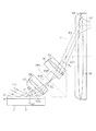
図4に示すように、この第2実施形態におけるエリプソメトリー顕微鏡1における結像系30は、1次結像系31及び2次結像系32とを有している。1次結像系31は1組の対物レンズ33,34で構成され、2次結像系32は1組をなす対物レンズ35及び結像レンズ36で構成されている。1組の対物レンズ33,34はそれぞれの光軸AX5,AX6を一致させ、かつ対物レンズ33,34の焦点面を一致させるように配置されている。また、1組をなす対物レンズ35及び結像レンズ36はそれぞれの光軸AX7,AX8を一致させ、かつ対物レンズ35及び結像レンズ36の焦点面を一致させるように配置されている。つまり、結像系30は、1組の対物レンズ33,34の焦点面を一致させると共に、1組をなす対物レンズ35及び結像レンズ36の焦点面を一致させたアフォーカル系の結像系となっている。
As shown in FIG. 4, the imaging system 30 in the
対物レンズ33の鏡筒37は反射光R1の絞りとして機能し、対物レンズ33を通過した反射光R2は両レンズ33,34の焦点面FP1まで集光した後、この焦点面FP1から拡散して、対物レンズ34の鏡筒38内の範囲に入射する。対物レンズ34を通過した反射光R3は平行光となって、1次結像面P1上に物体像を1次結像すると共に、2次結像系32を構成する対物レンズ35の鏡筒39内の範囲に入射する。対物レンズ35を通過した反射光R4は、両レンズ35,36の焦点面FP2まで集光した後、この焦点面FP2から拡散して結像レンズ36に入射し、結像レンズ36を通過した反射光R5は平行光となって検光子40に入射する。そして、検光子40を通った平行光の反射光R6は撮像素子24の検出面25(2次結像面P2)に入射して、その検出面25上に物体像を2次結像する。
第2実施形態においても、1次結像系31の倍率M1を、2次結像系32の倍率M2よりも小さく設定している(M1<M2)。
The
Also in the second embodiment, the magnification M1 of the primary imaging system 31 is set smaller than the magnification M2 of the secondary imaging system 32 (M1 <M2).
図5は、1次結像系31の模式側面図である。図5に示すように、本実施形態では、対物レンズ33の光軸AX5と試料面SPとのなす角度をθoと、対物レンズ34の光軸AX6と1次結像面P1とのなす角度をθ1とおくと、1次結像系31の倍率M1と角度θo,θ1との間には、第1実施形態で示した式(1)の関係が成立する。このため、この第2実施形態においても、1次結像系31を構成する少なくとも1つのレンズが、1組の対物レンズ33,34となっただけで、角度θo,θ1が共に45度に設定されている。そして、1次結像系31の倍率M1が1倍に設定されている。一例として、対物レンズ33,34は共に倍率1倍の対物レンズである。なお、本実施形態においても、角度θoは、想定される最小反射角(=60度)のときの反射光R1の光軸AX2と試料面SPとのなす角度(つまり反射角θref)に、ひねり角度Δθを加えた値として設定されている。このため、本実施形態においても、1次結像系31を通った平行光である反射光R3は、対物レンズ35に対して比較的小さな入射角(例えば60°程度)で入射することができる。
FIG. 5 is a schematic side view of the primary imaging system 31. As shown in FIG. 5, in this embodiment, the angle formed between the optical axis AX5 of the
角度θo,θ1、倍率M1がこのような条件に設定されることで、1次結像面P1は図4及び図5に示すように、対物レンズ34と対物レンズ35の間における空間上に形成される。そして、図4及び図5に示すように、2次結像系32を構成する対物レンズ35及び結像レンズ36は、1次結像面P1に対して各々の光軸AX7,AX8が垂直になるように、配置されている。そして、撮像素子24は、その検出面25の中心軸AX4が各光軸AX7,AX8と一致する状態に配置されると共に、その検出面25が2次結像面P2と重なるように配置されている。
By setting the angles θo and θ1 and the magnification M1 to such conditions, the primary imaging plane P1 is formed in the space between the
ところで、エリプソメトリー顕微鏡1では、試料Sからの反射光のうち基板2からの正反射光の強度が、薄膜3からの散乱光に比べ強い。検出すべき薄膜3の微小構造からの光はこの散乱光である。このため、微小構造をもつ薄膜3の像と正反射光のなす像が重畳された像が撮像素子24で検出される。正反射光は、試料面SPの微小膜厚構造に関する情報を含んでおらず、光源12の強度分布に対応した不要な光強度分布を生じる。これは背景光による像雑音となる。
By the way, in the
本実施形態によれば、前記第1実施形態と同様の効果の他に、次の効果が得られる。アフォーカル系の結像系30を採用することにより、背景光となる基板2からの正反射光は、撮像素子24の検出面25へ平行光として入射し、薄膜3の微細構造からの反射光は、種々の角度を持つ収束光となって入射・結像する。試料面SPからの正反射光による光源12の強度分布像は、無限遠に結像することと等価になり、輝度分布をより均一にすることができる。これにより、背景光による雑音像に関する問題を解決することができる。
According to the present embodiment, in addition to the same effects as those of the first embodiment, the following effects can be obtained. By adopting the afocal imaging system 30, the specularly reflected light from the
また、この結像系30は、1次結像系31及び2次結像系32において、結像させるべき物体(試料S)及び1次物体像(1次結像面P1上の像)が、それぞれの対物レンズ33、35に最も近接した配置とすることができる。すなわち、物体からの散乱光を最も効率的に集光できる配置とすることができる。結像対象から散乱光が光軸に対してなす角度が大きい本エリプソメトリー顕微鏡1においては、十分な光量を確保するためにも有効である。
Further, the imaging system 30 has an object (sample S) and a primary object image (image on the primary imaging plane P1) to be imaged in the primary imaging system 31 and the
以上のように、基板2上の薄膜3について、他の計測あるいは操作手段のための作業空間の確保と、高い面内分解能との両立を可能とし、さらに背景光による雑音像を抑制することができる。
なお、実施形態は以下のように変更してもよい。
As described above, with respect to the
In addition, you may change embodiment as follows.
・上記実施形態では、角度θo,θ1を、θo=θ1とした例を示したが、角度θo,θ1の最小関係は適宜に設定してよい。θo≧θ1が好ましいが、例えばθo<θ1としてもよい。 In the above embodiment, an example in which the angles θo and θ1 are set to θo = θ1 is shown, but the minimum relationship between the angles θo and θ1 may be set as appropriate. Although θo ≧ θ1 is preferable, for example, θo <θ1 may be set.
・実施形態において、1次結像系を構成する対物レンズにひねり角度Δθを加えない構成も採用できる。すなわち、対物レンズの光軸と反射光R1の光軸とを一致させるように対物レンズを配置してもよい。 In the embodiment, a configuration in which the twist angle Δθ is not added to the objective lens constituting the primary imaging system can also be adopted. That is, the objective lens may be arranged so that the optical axis of the objective lens coincides with the optical axis of the reflected light R1.
・実施形態において、エリプソメトリー顕微鏡1は、走査型プローブ顕微鏡との組合せで複合型顕微鏡を構成することに限定されない。例えば、試料Sに力学的な刺激を与えるための摺動用プローブ等の操作手段と組み合わせただけの構成でもよい。この構成のエリプソメトリー顕微鏡によれば、粘弾性を有する薄膜に力学的な刺激を与えた際の応答の様子を、高コントラストかつ高倍率で動的観察することができる。また、計測手段や走査手段は、必ずしも試料に接触する必要はなく、試料に近接して用いられるものでもよい。この種の操作手段としては、試料薄膜(例えば液体薄膜)に流体(例えばエア等の気体や、酸・アルカリ等の液体)を吹き付けるノズルや、試料薄膜(固体薄膜あるいは液体薄膜)に熱刺激を与える光加熱手段やヒーターなどが挙げられる。
In the embodiment, the
・実施形態において、1次結像系と2次結像系のうち少なくとも一方を複数段の結像系により構成してもよい。すなわち、1次結像系と2次結像系のうち少なくとも一方を、少なくとも1個のレンズを有する結像系を複数段並べて構成することができる。例えば2次結像系の場合、結像面は段数と同数設けられ、最終段の結像面が2次結像面となり、この2次結像面に撮像素子の検出面が一致するように撮像素子を配置しればよい。また、2次結像系を構成する複数段の結像系の各レンズはそれぞれの光軸が1次結像面に対して垂直に配置されることが好ましい。
・1次結像系及び2次結像系は、レンズが1個又は2個であることに限定されず、3個以上の複数個のレンズを備えてもよい。
・照明光の光束を絞る絞りを設けてもよい。対象により光束の径を絞ることでコントラストの改善を図ることができる。
In the embodiment, at least one of the primary imaging system and the secondary imaging system may be configured by a plurality of stages of imaging systems. That is, at least one of the primary imaging system and the secondary imaging system can be configured by arranging a plurality of imaging systems having at least one lens. For example, in the case of a secondary imaging system, the number of imaging planes is the same as the number of stages, and the final imaging plane is a secondary imaging plane so that the detection plane of the image sensor coincides with the secondary imaging plane. What is necessary is just to arrange | position an image pick-up element. In addition, it is preferable that the optical axes of the lenses of the multistage imaging system constituting the secondary imaging system are arranged perpendicular to the primary imaging plane.
The primary imaging system and the secondary imaging system are not limited to one or two lenses, and may include a plurality of three or more lenses.
-You may provide the stop which restrict | squeezes the light beam of illumination light. The contrast can be improved by reducing the diameter of the light beam depending on the object.
・位相補償子16は、λ/4板に替えて、石英製の光弾性変調器としてもよい。位相変調型として高速に位相補償子の変調を行うことができる。CCDカメラとの組合せで高速に処理することができる。
The
・斜め照明系、結像系ともに模式的な図で説明しているものであり、これと等価の光学系とすることができることは言うまでもない。又、当業者によりその構成は付加され、省略され、置き換えられて実施されうることはもちろんである。 -Both the oblique illumination system and the imaging system are explained with schematic diagrams, and it goes without saying that an optical system equivalent to this can be obtained. Further, it goes without saying that the configuration can be added, omitted, or replaced by those skilled in the art.
・本発明のエリプソメトリー装置は、試料を拡大して観察する機能を有するエリプソメトリー顕微鏡に適用できることはもちろん、膜厚分布測定を行うエリプソメータにも適用できる。また、エリプソメトリー装置には、例えば、工業用途で、ディスク表面の潤滑膜、ナノインプリントリソグラフィーにおける液体薄膜、ポリマーエレクトロニクスにおける液体分子薄膜などの薄膜の膜厚分布測定を、偏光解析法(エリプソメトリー)を用いて行う薄膜検査装置なども含まれる。
以下、前記各実施形態及び変形例から把握される技術的思想を以下に記載する。
The ellipsometry apparatus of the present invention can be applied not only to an ellipsometry microscope having a function of observing a sample in an enlarged manner, but also to an ellipsometer that performs film thickness distribution measurement. For ellipsometry equipment, for example, in industrial applications, film thickness distribution measurement of thin films such as lubricating films on disk surfaces, liquid thin films in nanoimprint lithography, and liquid molecular thin films in polymer electronics, ellipsometry is used. Also included are thin film inspection devices that are used.
Hereinafter, the technical idea grasped from the respective embodiments and modifications will be described below.
(1)前記1次結像系は、前記レンズとして1つの対物レンズを有し、前記2次結像系は、前記レンズとして1つの対物レンズを有することを特徴とする請求項1乃至6のいずれか一項に記載のエリプソメトリー装置。この構成よれば、1次結像系と2次結像系にそれぞれ対物レンズが1つずつ設けられた構成なので、結像系を複数段にした割に、結像系の構成が簡単で済む。 (1) The primary imaging system has one objective lens as the lens, and the secondary imaging system has one objective lens as the lens. The ellipsometry apparatus according to any one of the above. According to this configuration, since one objective lens is provided for each of the primary imaging system and the secondary imaging system, the configuration of the imaging system can be simplified even though the imaging system is divided into a plurality of stages. .
(2)前記1次結像系及び前記2次結像系は、それぞれ少なくとも1組のレンズを含み、当該少なくとも1組のレンズを組毎に焦点面を一致させた構成のアフォーカル系としたことを特徴とする請求項1乃至6のいずれか一項に記載のエリプソメトリー装置。この構成によれば、1次結像系及び2次結像系はアフォーカル系であるので、物体における観察対象以外の部分で正反射した背景光は、撮像素子の検出面に平行光として入射し、物体からの反射光は、種々の角度を持つ収束光となって入射・結像する。物体面からの正反射光による強度分布像は、無限遠に結像することと等価になり、輝度分布をより均一にすることができる。これにより、背景光による雑音像を低減できる。
(2) The primary imaging system and the secondary imaging system each include at least one set of lenses, and the at least one set of lenses is an afocal system having a configuration in which focal planes coincide with each other. The ellipsometry apparatus according to any one of
(3)前記第2の倍率は、10倍以上でかつ前記第1の倍率の10倍以上の倍率であることを特徴とする請求項1乃至6のいずれか一項に記載のエリプソメトリー装置。この構成によれば、第1の倍率が低倍率でも、エリプソメトリー装置により物体像を高倍率で観察できる。
(3) The ellipsometry apparatus according to any one of
(4)前記物体面に対して法線方向観察側の位置に前記物体面に対して接触する操作が可能な操作手段を備えたことを特徴とする請求項1乃至6のいずれか一項に記載のエリプソメトリー装置。この構成によれば、斜め照明系及び結像系が、物体面に対する照明光の入射元側の位置及び反射光の反射先側の位置にそれぞれ配置され、物体面に対して法線方向観察側の位置にできた空間を、操作手段の作業空間として利用できる。例えば、物体に操作手段を接触させる操作をしながら、物体面の動的観察を行うことができる。
(4) The operation unit according to any one of
(5)請求項1乃至6のいずれか一項に記載のエリプソメトリー装置としてのエリプソメトリー顕微鏡と、前記物体面に対して法線方向観察側の位置に前記物体面に対して接触可能なプローブを配置する走査型プローブ顕微鏡とを備えた複合型顕微鏡。この複合型顕微鏡によれば、エリプソメトリー顕微鏡により物体を広い視野で高倍率で観察し、そのうち特に微細構造を観察したい注目箇所を走査型プローブ顕微鏡でさらに高い倍率で観察できる。
(5) An ellipsometry microscope as the ellipsometry apparatus according to any one of
1…エリプソメトリー装置としてのエリプソメトリー顕微鏡、2…基板、3…薄膜、4…斜め照明系、5…結像系、10…1次結像系、11…2次結像系、12…光源、13…光ファイバ、14…コリメートレンズ、15…偏光子、16…位相補償子(λ/4板)、17…コリメートレンズ、21…1次結像系のレンズを構成する対物レンズ、22…2次結像系のレンズを構成する結像レンズ、23…検光子、24…撮像素子、25…検出面、26…鏡筒、27…鏡筒、28…モニタ、30…アフォーカル系の結像系、31…1次結像系、32…2次結像系、33,34…1次結像系のレンズを構成する対物レンズ、35…2次結像系のレンズを構成する対物レンズ、36…2次結像系のレンズを構成する結像レンズ、40…検光子、70…走査型プローブ顕微鏡、71…プローブ、72…変位系、80…複合型顕微鏡、M1…第1の倍率としての倍率、M2…第2の倍率としての倍率、S…物体としての試料、SP…物体面として試料面、L1〜L4…照明光、R1〜R3…反射光(第1実施形態)、R1〜R5…反射光(第2実施形態)、P1…1次結像系の結像面としての1次結像面、P2…2次結像系の結像面としての2次結像面、θo…角度、θ1…角度、θref…反射角、θrefmin…最小反射角、Δθ…ひねり角度、AX1,AX3,AX5,AX6,AX7,AX8…レンズの光軸、AX2…反射光の光軸、AX4…撮像素子の中心軸、FP1,FP2…焦点面。
DESCRIPTION OF
Claims (6)
光源の光路上に偏光子と位相補償子とを有し、当該偏光子及び位相補償子を通った平行光を前記物体に斜めに照射する斜め照明系と、
物体からの反射光を入射して物体像を拡大して結像させる結像系と、
前記結像系における前記反射光の光路の途中に設けられた検光子と、
前記結像系により結像された像を撮像する撮像素子と、を備え、
前記結像系は、
前記物体からの反射光を入射して第1の倍率で物体像を結像させる少なくとも一つのレンズを含む1次結像系と、
前記1次結像系が結像した物体像を前記第1の倍率より大きな第2の倍率で拡大する少なくとも一つのレンズを含む2次結像系と、
を備えたことを特徴とするエリプソメトリー装置。 An ellipsometry apparatus capable of magnifying and observing an image of an object to be observed using ellipsometry,
A slant illumination system having a polarizer and a phase compensator on an optical path of a light source, and obliquely illuminating the object with parallel light passing through the polarizer and the phase compensator;
An imaging system for enlarging an object image by incident reflected light from the object;
An analyzer provided in the middle of the optical path of the reflected light in the imaging system;
An image pickup device for picking up an image formed by the image forming system,
The imaging system is
A primary imaging system that includes at least one lens that receives reflected light from the object and forms an object image at a first magnification;
A secondary imaging system including at least one lens for enlarging an object image formed by the primary imaging system at a second magnification larger than the first magnification;
An ellipsometry apparatus characterized by comprising:
前記2次結像系の光軸を、前記1次結像系の結像面と略垂直になるように配置するとともに、前記2次結像系の結像面が前記撮像素子の検出面と略重なるように前記撮像素子を配置したことを特徴とするエリプソメトリー装置。 The ellipsometry apparatus according to claim 1,
The optical axis of the secondary imaging system is arranged so as to be substantially perpendicular to the imaging surface of the primary imaging system, and the imaging surface of the secondary imaging system is connected to the detection surface of the image sensor. An ellipsometry apparatus in which the imaging elements are arranged so as to substantially overlap.
前記1次結像系の光軸と物体面とのなす角度θo、前記光軸と前記1次結像系の結像面とのなす角度θ1とした場合、
前記1次結像系の倍率M1は、M1=tanθo/tanθ1において、角度θ1を20度以上としうる値に設定されていることを特徴とするエリプソメトリー装置。 The ellipsometry apparatus according to claim 1 or 2,
When the angle θo formed between the optical axis of the primary imaging system and the object plane and the angle θ1 formed between the optical axis and the imaging plane of the primary imaging system,
An ellipsometry apparatus characterized in that the magnification M1 of the primary imaging system is set to a value that allows the angle θ1 to be 20 degrees or more when M1 = tan θo / tan θ1.
前記1次結像系の倍率M1は、0.3〜3倍の範囲内の値に設定されていることを特徴とするエリプソメトリー装置。 The ellipsometry apparatus according to any one of claims 1 to 3,
An ellipsometry apparatus characterized in that the magnification M1 of the primary imaging system is set to a value within a range of 0.3 to 3 times.
前記1次結像系の光軸と物体面とのなす角度θoと、前記光軸と前記1次結像系の結像面とのなす角度θ1は、θo≧θ1を満たし、M1=tanθo/tanθ1により決まる前記1次結像系の倍率M1は1倍以上に設定されていることを特徴とするエリプソメトリー装置。 The ellipsometry apparatus according to claim 3 or 4,
The angle θo formed by the optical axis of the primary imaging system and the object plane and the angle θ1 formed by the optical axis and the imaging plane of the primary imaging system satisfy θo ≧ θ1, and M1 = tan θo / An ellipsometry apparatus characterized in that the magnification M1 of the primary imaging system determined by tan θ1 is set to 1 or more.
物体のp偏光に対する反射率が略最小となるような入射角で前記物体に照明光を照射して観察又は膜厚分布測定が行われる構成であり、
前記1次結像系の光軸は、物体面からの反射光の光軸が想定される最小反射角をとるときの当該光軸に対して前記物体面から離れる方向へひねり角度Δθだけ傾けて配置されていることを特徴とするエリプソメトリー装置。 The ellipsometry apparatus according to any one of claims 1 to 5,
It is a configuration in which observation or film thickness distribution measurement is performed by irradiating the object with illumination light at an incident angle such that the reflectance of the object with respect to p-polarized light is substantially minimum
The optical axis of the primary imaging system is tilted by a twist angle Δθ in a direction away from the object plane with respect to the optical axis when the optical axis of the reflected light from the object plane takes the assumed minimum reflection angle. An ellipsometry device characterized by being arranged.
Priority Applications (1)
| Application Number | Priority Date | Filing Date | Title |
|---|---|---|---|
| JP2009257187A JP5648780B2 (en) | 2009-11-10 | 2009-11-10 | Ellipsometer |
Applications Claiming Priority (1)
| Application Number | Priority Date | Filing Date | Title |
|---|---|---|---|
| JP2009257187A JP5648780B2 (en) | 2009-11-10 | 2009-11-10 | Ellipsometer |
Publications (2)
| Publication Number | Publication Date |
|---|---|
| JP2011102731A true JP2011102731A (en) | 2011-05-26 |
| JP5648780B2 JP5648780B2 (en) | 2015-01-07 |
Family
ID=44193121
Family Applications (1)
| Application Number | Title | Priority Date | Filing Date |
|---|---|---|---|
| JP2009257187A Active JP5648780B2 (en) | 2009-11-10 | 2009-11-10 | Ellipsometer |
Country Status (1)
| Country | Link |
|---|---|
| JP (1) | JP5648780B2 (en) |
Cited By (6)
| Publication number | Priority date | Publication date | Assignee | Title |
|---|---|---|---|---|
| JP2013167857A (en) * | 2012-01-19 | 2013-08-29 | Lasertec Corp | Microscope and inspection device |
| WO2017038219A1 (en) * | 2015-09-02 | 2017-03-09 | 株式会社目白67 | Observation device |
| JP2019200651A (en) * | 2018-05-17 | 2019-11-21 | オリンパス株式会社 | Information processor, method for processing information, and program |
| JP2021189061A (en) * | 2020-06-01 | 2021-12-13 | 株式会社日立ハイテクサイエンス | Microscope system and method for observing sample using microscope system |
| JP2023512258A (en) * | 2020-01-30 | 2023-03-24 | ケーエルエー コーポレイション | Overlay metrology of bonded wafers |
| JP7429277B1 (en) | 2022-08-10 | 2024-02-07 | シャンハイ インスティテュート オブ メジャメント アンド テスティング テクノロジー | Film thickness measurement device and measurement method based on laser ellipsometric system |
Citations (7)
| Publication number | Priority date | Publication date | Assignee | Title |
|---|---|---|---|---|
| JPS462940B1 (en) * | 1967-07-07 | 1971-01-25 | ||
| JPS4973197A (en) * | 1972-11-11 | 1974-07-15 | ||
| JPH0791924A (en) * | 1993-09-21 | 1995-04-07 | Nkk Corp | Ellipso parameter measuring method and ellipsometer |
| JPH07218859A (en) * | 1994-02-07 | 1995-08-18 | Olympus Optical Co Ltd | Image display device |
| JPH086263A (en) * | 1994-06-20 | 1996-01-12 | Nikon Corp | Surface position detector |
| JP2000098247A (en) * | 1998-09-21 | 2000-04-07 | Agency Of Ind Science & Technol | Total focus reflection type optical microscope |
| JP2009192331A (en) * | 2008-02-13 | 2009-08-27 | Univ Nagoya | Film thickness distribution measuring device |
-
2009
- 2009-11-10 JP JP2009257187A patent/JP5648780B2/en active Active
Patent Citations (7)
| Publication number | Priority date | Publication date | Assignee | Title |
|---|---|---|---|---|
| JPS462940B1 (en) * | 1967-07-07 | 1971-01-25 | ||
| JPS4973197A (en) * | 1972-11-11 | 1974-07-15 | ||
| JPH0791924A (en) * | 1993-09-21 | 1995-04-07 | Nkk Corp | Ellipso parameter measuring method and ellipsometer |
| JPH07218859A (en) * | 1994-02-07 | 1995-08-18 | Olympus Optical Co Ltd | Image display device |
| JPH086263A (en) * | 1994-06-20 | 1996-01-12 | Nikon Corp | Surface position detector |
| JP2000098247A (en) * | 1998-09-21 | 2000-04-07 | Agency Of Ind Science & Technol | Total focus reflection type optical microscope |
| JP2009192331A (en) * | 2008-02-13 | 2009-08-27 | Univ Nagoya | Film thickness distribution measuring device |
Cited By (14)
| Publication number | Priority date | Publication date | Assignee | Title |
|---|---|---|---|---|
| US9013787B2 (en) | 2012-01-19 | 2015-04-21 | Lasertec Corporation | Microscope and inspection apparatus |
| JP2013167857A (en) * | 2012-01-19 | 2013-08-29 | Lasertec Corp | Microscope and inspection device |
| WO2017038219A1 (en) * | 2015-09-02 | 2017-03-09 | 株式会社目白67 | Observation device |
| JP2017049438A (en) * | 2015-09-02 | 2017-03-09 | 株式会社目白67 | Observation device |
| CN107924047A (en) * | 2015-09-02 | 2018-04-17 | 株式会社目白67 | Observe device |
| JP2019200651A (en) * | 2018-05-17 | 2019-11-21 | オリンパス株式会社 | Information processor, method for processing information, and program |
| JP7064952B2 (en) | 2018-05-17 | 2022-05-11 | オリンパス株式会社 | Information processing equipment, information processing methods and programs |
| JP7653445B2 (en) | 2020-01-30 | 2025-03-28 | ケーエルエー コーポレイション | Overlay Metrology of Bonded Wafers |
| JP2023512258A (en) * | 2020-01-30 | 2023-03-24 | ケーエルエー コーポレイション | Overlay metrology of bonded wafers |
| JP2021189061A (en) * | 2020-06-01 | 2021-12-13 | 株式会社日立ハイテクサイエンス | Microscope system and method for observing sample using microscope system |
| JP2024053081A (en) * | 2020-06-01 | 2024-04-12 | 株式会社日立ハイテクサイエンス | Microscope system and method for observing a sample using the microscope system |
| JP7545001B2 (en) | 2020-06-01 | 2024-09-03 | 株式会社日立ハイテクサイエンス | Microscope system and method for observing a sample using the microscope system |
| JP2024025607A (en) * | 2022-08-10 | 2024-02-26 | シャンハイ インスティテュート オブ メジャメント アンド テスティング テクノロジー | Film thickness measurement device and measurement method based on laser ellipsometric system |
| JP7429277B1 (en) | 2022-08-10 | 2024-02-07 | シャンハイ インスティテュート オブ メジャメント アンド テスティング テクノロジー | Film thickness measurement device and measurement method based on laser ellipsometric system |
Also Published As
| Publication number | Publication date |
|---|---|
| JP5648780B2 (en) | 2015-01-07 |
Similar Documents
| Publication | Publication Date | Title |
|---|---|---|
| CN110987817B (en) | Ellipsometer integrating dark field observation based on large-numerical-aperture objective lens and measurement method | |
| US10983328B2 (en) | Structured illumination microscope apparatus and an image forming apparatus | |
| JP5035904B2 (en) | Film thickness distribution measuring device | |
| JP4312777B2 (en) | Confocal self-interference microscope with side lobes removed | |
| US11635289B2 (en) | Surface shape measurement device and surface shape measurement method | |
| JP5648780B2 (en) | Ellipsometer | |
| JP6224595B2 (en) | Microscope device | |
| TWI448661B (en) | Interferometer utilizing polarization scanning | |
| CN217639720U (en) | Failure analysis microscope | |
| US20180149987A1 (en) | Alignment system | |
| JP2007506070A (en) | Triangulation method and system for determining surface shape through thin film coating | |
| JP6358577B2 (en) | Scanning optical microscope | |
| TW202332901A (en) | Systems and methods for concurrent measurements of interferometric and ellipsometric signals of multi-layer thin films | |
| WO1997044633A1 (en) | Optical measurement | |
| JP2010121960A (en) | Measuring device and method of measuring subject | |
| JP5448225B2 (en) | Quantitative phase measuring device | |
| KR20180125621A (en) | Overlay metrology using the near infra-red spectral range | |
| JP6142996B2 (en) | Via shape measuring device and via inspection device | |
| US10371501B2 (en) | Method for determining height information of a sample, and scanning microscope | |
| WO2023135681A1 (en) | Surface inspecting device | |
| JP5668566B2 (en) | Microscope apparatus and observation method | |
| JP2009198205A (en) | Interferometer | |
| JP3294246B2 (en) | Confocal microscope | |
| Ibrahim | A series of microscope objective lenses combined with an interferometer for individual nanoparticles detection | |
| Sheppard et al. | Low-coherence interference microscopy |
Legal Events
| Date | Code | Title | Description |
|---|---|---|---|
| A621 | Written request for application examination |
Free format text: JAPANESE INTERMEDIATE CODE: A621 Effective date: 20121109 |
|
| A977 | Report on retrieval |
Free format text: JAPANESE INTERMEDIATE CODE: A971007 Effective date: 20130903 |
|
| A131 | Notification of reasons for refusal |
Free format text: JAPANESE INTERMEDIATE CODE: A131 Effective date: 20131029 |
|
| A521 | Request for written amendment filed |
Free format text: JAPANESE INTERMEDIATE CODE: A523 Effective date: 20131218 |
|
| A131 | Notification of reasons for refusal |
Free format text: JAPANESE INTERMEDIATE CODE: A131 Effective date: 20140701 |
|
| A521 | Request for written amendment filed |
Free format text: JAPANESE INTERMEDIATE CODE: A523 Effective date: 20140822 |
|
| TRDD | Decision of grant or rejection written | ||
| A01 | Written decision to grant a patent or to grant a registration (utility model) |
Free format text: JAPANESE INTERMEDIATE CODE: A01 Effective date: 20141007 |
|
| A61 | First payment of annual fees (during grant procedure) |
Free format text: JAPANESE INTERMEDIATE CODE: A61 Effective date: 20141028 |
|
| R150 | Certificate of patent or registration of utility model |
Ref document number: 5648780 Country of ref document: JP Free format text: JAPANESE INTERMEDIATE CODE: R150 |
|
| R250 | Receipt of annual fees |
Free format text: JAPANESE INTERMEDIATE CODE: R250 |
|
| R250 | Receipt of annual fees |
Free format text: JAPANESE INTERMEDIATE CODE: R250 |
|
| R250 | Receipt of annual fees |
Free format text: JAPANESE INTERMEDIATE CODE: R250 |
|
| S533 | Written request for registration of change of name |
Free format text: JAPANESE INTERMEDIATE CODE: R313533 |
|
| R350 | Written notification of registration of transfer |
Free format text: JAPANESE INTERMEDIATE CODE: R350 |
|
| R250 | Receipt of annual fees |
Free format text: JAPANESE INTERMEDIATE CODE: R250 |
|
| R250 | Receipt of annual fees |
Free format text: JAPANESE INTERMEDIATE CODE: R250 |