JP2011123473A - Image processing apparatus and program - Google Patents
Image processing apparatus and program Download PDFInfo
- Publication number
- JP2011123473A JP2011123473A JP2010160612A JP2010160612A JP2011123473A JP 2011123473 A JP2011123473 A JP 2011123473A JP 2010160612 A JP2010160612 A JP 2010160612A JP 2010160612 A JP2010160612 A JP 2010160612A JP 2011123473 A JP2011123473 A JP 2011123473A
- Authority
- JP
- Japan
- Prior art keywords
- colorless plate
- image processing
- processing apparatus
- image
- plate pattern
- Prior art date
- Legal status (The legal status is an assumption and is not a legal conclusion. Google has not performed a legal analysis and makes no representation as to the accuracy of the status listed.)
- Granted
Links
Images



Classifications
-
- H—ELECTRICITY
- H04—ELECTRIC COMMUNICATION TECHNIQUE
- H04N—PICTORIAL COMMUNICATION, e.g. TELEVISION
- H04N1/00—Scanning, transmission or reproduction of documents or the like, e.g. facsimile transmission; Details thereof
- H04N1/46—Colour picture communication systems
- H04N1/54—Conversion of colour picture signals to a plurality of signals some of which represent particular mixed colours, e.g. for textile printing
-
- B—PERFORMING OPERATIONS; TRANSPORTING
- B41—PRINTING; LINING MACHINES; TYPEWRITERS; STAMPS
- B41J—TYPEWRITERS; SELECTIVE PRINTING MECHANISMS, i.e. MECHANISMS PRINTING OTHERWISE THAN FROM A FORME; CORRECTION OF TYPOGRAPHICAL ERRORS
- B41J2/00—Typewriters or selective printing mechanisms characterised by the printing or marking process for which they are designed
- B41J2/005—Typewriters or selective printing mechanisms characterised by the printing or marking process for which they are designed characterised by bringing liquid or particles selectively into contact with a printing material
- B41J2/01—Ink jet
- B41J2/21—Ink jet for multi-colour printing
- B41J2/2107—Ink jet for multi-colour printing characterised by the ink properties
- B41J2/2114—Ejecting specialized liquids, e.g. transparent or processing liquids
Landscapes
- Engineering & Computer Science (AREA)
- Textile Engineering (AREA)
- Multimedia (AREA)
- Signal Processing (AREA)
- Facsimile Image Signal Circuits (AREA)
- Color Image Communication Systems (AREA)
- Control Or Security For Electrophotography (AREA)
- Color, Gradation (AREA)
- Color Electrophotography (AREA)
- Facsimiles In General (AREA)
- Image Processing (AREA)
- Image Analysis (AREA)
- Processing Or Creating Images (AREA)
Abstract
【課題】印刷される画像に好適な無色版を一般のユーザが容易に生成できるようにする。
【解決手段】領域分割部34は予め定められた特徴により、入力画像の複数の領域に分割する。領域特徴抽出部35は、領域分割された入力画像を用いて各領域の特徴を算出する。無色版生成部36は、予め作成された領域特徴と無色版パターンとの関係を示す領域特徴−無色版パターンテーブル41を参照して、領域毎の無色版を作成し、出力する。領域特徴として、平均輝度、輝度の標準偏差を用いることができる。
【選択図】図2To enable a general user to easily generate a colorless plate suitable for an image to be printed.
An area dividing unit divides an input image into a plurality of areas according to predetermined characteristics. The region feature extraction unit 35 calculates the feature of each region using the input image divided into regions. The colorless plate generation unit 36 creates and outputs a colorless plate for each region with reference to the region feature-colorless plate pattern table 41 indicating the relationship between the region feature and the colorless plate pattern created in advance. The average luminance and the standard deviation of luminance can be used as the region feature.
[Selection] Figure 2
Description
本発明は、無色のトナーもしくはインクなどの記録剤を使用し、電子写真記録方式やインクジェット記録方式などにより画像形成を行う、プリンタ、複写機、印刷機などの画像形成装置に好適な画像処理装置及びプログラムに関するものである。 The present invention relates to an image processing apparatus suitable for an image forming apparatus such as a printer, a copying machine, or a printing machine, which uses a recording agent such as colorless toner or ink, and forms an image by an electrophotographic recording system or an inkjet recording system. And programs.
このような画像形成装置において、印刷物の表面保護や、表面光沢の変化による画像表現の改善を目的として、無色のトナーもしくはインク(以下クリアトナー)を用いた無色版を利用することがある。 In such an image forming apparatus, a colorless plate using colorless toner or ink (hereinafter, clear toner) may be used for the purpose of protecting the surface of a printed material or improving image expression due to a change in surface gloss.
クリアトナーは独自の色を持たないため、画像の制作者の意図により様々なパターンを持つことが可能である。例えば特許文献1には、クリアトナーにより付与可能なテクスチャ(クリアトナーパターン)を予めコンピュータの記憶装置に複数格納しておき、オペレータがコンピュータのディスプレイ上でテクスチャを付与する領域を指定し、さらにプルダウンメニューを用いてテクスチャを選択することが記載されている。また、特許文献2には、画像形成装置の操作パネル上でロゴや波模様などのクリアイメージ画像(クリアトナーパターン)を登録することが記載されている。
Since clear toner does not have a unique color, it can have various patterns depending on the intention of the image creator. For example, in
しかし、これらの文献に記載されている技術は、その高い自由度のため、逆に一般のユーザにとっては好適な無色版を生成することが難しいという問題がある。 However, the techniques described in these documents have a problem that it is difficult to generate a colorless plate suitable for general users because of the high degree of freedom.
本発明は、このような問題を解決するためになされたものであり、その目的は、印刷される画像に好適な無色版を一般のユーザが容易に生成できるようにすることである。 The present invention has been made to solve such a problem, and an object thereof is to enable a general user to easily generate a colorless plate suitable for an image to be printed.
本発明の画像処理装置では、入力画像を複数の領域に分割し、分割された各領域の特徴を求め、その特徴に応じて各領域に適した無色版パターンを決定する。 In the image processing apparatus of the present invention, an input image is divided into a plurality of areas, the characteristics of each divided area are obtained, and a colorless plate pattern suitable for each area is determined according to the characteristics.
最も単純には、1種類以上の特徴からなる特徴セットにより張られる特徴空間と無色版パターンとの間の対応を示すルックアップテーブルを予め定めておき、各領域の特徴セットを用いてルックアップテーブルを参照し、その特徴セットに対応する無色版パターンを決定する。 In the simplest case, a look-up table indicating the correspondence between a feature space spanned by a feature set composed of one or more types of features and the colorless plate pattern is determined in advance, and the look-up table is used using the feature set of each region. The colorless plate pattern corresponding to the feature set is determined.
上記ルックアップテーブルは以前のn個(nは2以上の整数)の入力特徴セットと無色版パターンを利用して、例えばサポートベクターマシン(Support Vector Machine:SVM)などを用いて判別器を学習、作成することができる。 The above lookup table uses the previous n input feature sets (where n is an integer greater than or equal to 2) and a colorless plate pattern to learn the discriminator using, for example, a Support Vector Machine (SVM). Can be created.
特定の入力画像に対して好適な無色版パターンをユーザが手動作成することは困難であるため、ユーザに対して簡便な無色版パターン作成手段を提供することで、本発明の利用可能性を高める。この目的のため、本発明では、ユーザが容易に理解できるキーワードリストと、前記無色版パターンとを対応付けたルックアップテーブルを予め作成しておき、ユーザにキーワードリストを表示し、キーワードを選択させることで、入力画像に対する無色版パターンを決定する。 Since it is difficult for the user to manually create a colorless plate pattern suitable for a specific input image, providing a simple colorless plate pattern creating means for the user increases the applicability of the present invention. . For this purpose, in the present invention, a look-up table in which a keyword list that can be easily understood by a user and the colorless plate pattern are associated with each other is created in advance, and the keyword list is displayed for the user to select a keyword. Thus, a colorless plate pattern for the input image is determined.
キーワードリストを用いたユーザによる処理選択は2つある。入力画像の領域分割に対するもの、及び各領域に対する無色版パターンの選択に対するものである。 There are two user process selections using the keyword list. This is for the area division of the input image and for the selection of the colorless plate pattern for each area.
入力画像の領域分割に対する処理としては、例えば分割の細かさをキーワードリストで選択する処理がある。この場合、例えば、「大まかに」、「詳細に」などの語句と、領域分割のパラメータ、例えば領域分割の前処理としての低解像度化処理のパラメータを関連付けることで、キーワードリストと領域分割処理パラメータの関連付けが可能である。 As processing for region division of an input image, for example, there is processing for selecting the fineness of division from a keyword list. In this case, for example, by associating phrases such as “roughly” and “in detail” with a parameter for region division, for example, a parameter for low resolution processing as preprocessing for region division, the keyword list and the region division processing parameter Can be associated.
各領域に対する無色版パターンの選択に関してはまず、キーワードリストと無色版パターンを、既存の入力画像と無色版パターンとの関係から学習する。キーワードリストは予めシステム作成者が作成しておくことができる。これは例えば「JAGAT:印刷物の総合評価:http://www.jagat.or.jp/story_memo_view.asp?StoryID=10431」に例示されているような感性を表す語句(滑らか、しっとりしている、メリハリがきいている、・・・)の組を利用することができる。システム作成者はこのキーワードそれぞれに対して、想定される無色版パターンを対応付ける。この過程は別途既存例からの学習を利用してもよい。 Regarding the selection of the colorless plate pattern for each region, first, the keyword list and the colorless plate pattern are learned from the relationship between the existing input image and the colorless plate pattern. The keyword list can be created in advance by the system creator. This is, for example, a phrase representing sensitivity (smooth, moist, You can use the set of sharpness. The system creator associates an assumed colorless plate pattern with each of these keywords. This process may separately use learning from existing examples.
電子写真プロセスでは、トナーを紙に転写し熱と圧力を加えることで定着させるため、紙面に付着可能なトナー量と盛りの高さ(パイルハイト)には制約がある。そのため印刷物の表面造形で触覚に訴えかけるためには、上記制約を考慮した無色版パターンを生成する必要がある。 In the electrophotographic process, toner is transferred to paper and fixed by applying heat and pressure, so there are restrictions on the amount of toner that can adhere to the paper and the height of the pile (pile height). Therefore, in order to appeal to the tactile sensation in the surface modeling of the printed matter, it is necessary to generate a colorless plate pattern in consideration of the above restrictions.
そこで、電子写真プロセスの内、特に定着処理に関する情報として、定着ローラ―のニップ幅、定着温度、トナー種類を用いることで、紙面上に形成可能なトナーの高さ(パイルハイト)を予測する。 Therefore, the height (pile height) of the toner that can be formed on the paper surface is predicted by using the nip width of the fixing roller, the fixing temperature, and the toner type as information regarding the fixing process in the electrophotographic process.
また、印刷に用いる紙種に関して、紙の厚さを代表する情報としての紙の重さを、紙面表面の特性を代表する情報として、紙の白色度、光沢度、表面平滑度を利用し、印刷状態を予測する。 In addition, regarding the paper type used for printing, the weight of the paper as information representing the thickness of the paper, the information representing the characteristics of the paper surface, the whiteness, glossiness, and surface smoothness of the paper are used. Predict the printing status.
さらに、ユーザによる指定などで、クリアトナーを乗せる画像領域を決定した後、その領域を代表する特徴として、平均輝度及び標準偏差を用いることで、その領域からユーザが受ける表面造形の印象(ざらついている、滑らかである、など)を予測する。 Furthermore, after determining the image area on which the clear toner is to be placed, as specified by the user, the average luminance and standard deviation are used as features representing the area, and the impression of the surface modeling that the user receives from the area (roughness Is smooth, etc.).
予測を行う前に予測に必要なデータを取得するための予備実験を行い、領域の平均輝度、標準偏差の組み合わせと、印刷物上で期待される諸効果(凹凸感や光沢感)を対応付けておく。また同様に、その効果とそれを実現するための印刷パターンについても対応付けておく。この対応付けには、前記の定着処理に対する制約情報を用いる。この対応付けは、ユーザが行った処理の結果をもとに決定してもよいし、設計者が一意に対応付けてもよい。この対応付けは作像エンジン毎に作成してもよいし、一組みの対応付けで全ての作像エンジンに対応させてもよい。対応付けはルックアップテーブルで管理する。これにより、印刷に用いる作像エンジンの特性を無色版生成に加味し、印刷物上のクリアトナーによる効果を予測することが可能となる。 Preliminary experiments are performed to obtain the data necessary for the prediction before making a prediction, and the combination of the average brightness and standard deviation of the area is associated with various effects (feeling of unevenness and glossiness) expected on the printed matter. deep. Similarly, the effect is associated with the print pattern for realizing it. For this association, the restriction information for the fixing process is used. This association may be determined based on the result of processing performed by the user, or may be uniquely associated by the designer. This association may be created for each image forming engine, or may be made to correspond to all image forming engines by a set of associations. The association is managed with a lookup table. Thereby, it is possible to predict the effect of the clear toner on the printed matter by adding the characteristics of the image forming engine used for printing to the generation of the colorless plate.
予測処理では、新たな入力画像が与えられた場合、ユーザによる指定などで、クリアトナーを乗せる画像領域を決定(領域分割)した後、その領域の平均輝度と標準偏差を算出し、これらの値と予め定義されている上記の対応付け(ルックアップテーブル)により、その領域に与える無色版パターンを決定する。 In the prediction process, when a new input image is given, the image area on which the clear toner is placed is determined (area division) by the user's designation, etc., and then the average luminance and standard deviation of the area are calculated, and these values are calculated. The colorless plate pattern to be given to the area is determined based on the above-described association (lookup table).
[作用]
本発明によれば、画像の特徴セットにより張られる特徴空間と無色版パターンとの間の対応関係を示すルックアップテーブルを予め作成しておき、入力画像の各領域の特徴セットを求め、各領域の特徴セットを用いて前記ルックアップテーブルを参照し、特徴セットに対応する無色版パターンを決定し、その無色版パターンを用いて各領域の無色版を生成する。
[Action]
According to the present invention, a lookup table indicating the correspondence between the feature space spanned by the feature set of the image and the colorless plate pattern is created in advance, the feature set of each region of the input image is obtained, A colorless plate pattern corresponding to the feature set is determined by referring to the look-up table using the feature set, and a colorless plate of each region is generated using the colorless plate pattern.
本発明の画像処理装置を使用することにより、ユーザは簡便に、画像の各領域に適した無色版を生成し、利用することができる。 By using the image processing apparatus of the present invention, a user can easily generate and use a colorless plate suitable for each region of an image.
以下、本発明の実施の形態について、図面を参照して説明する。
[第1の実施形態]
〈画像形成システムの構成〉
図1に本発明の第1の実施形態の画像処理装置を有する画像形成システムを示す。この画像形成システムは、ネットワーク2と、それぞれがネットワーク2に接続された画像処理装置1、画像取得装置3、画像出力装置4、及び記憶装置5からなる。
Embodiments of the present invention will be described below with reference to the drawings.
[First Embodiment]
<Configuration of image forming system>
FIG. 1 shows an image forming system having an image processing apparatus according to a first embodiment of the present invention. This image forming system includes a
画像取得装置3はイメージスキャナやデジタルカメラなど、写真、原稿、風景などの画像の画像情報を取得する装置である。画像出力装置4は電子写真記録方式やインクジェット記録方式のプリンタやプロッタからなる画像を形成する装置である。記憶装置5はHDD(ハードディスクドライブ)などの大容量の外部記憶装置である。
The
画像処理装置1は、コンピュータにより構成されており、画像処理装置内部バス11と、それぞれが画像処理装置内部バス11に接続されたCPU(Central Processing Unit)12、ROM(Read Only Memory)13、RAM(Random Access Memory)14、記憶装置15、操作装置16、表示装置17、及び通信装置18を有する。
The
CPU12は、ROM13や記憶装置15に格納されているプログラムやデータをRAM14に読み込んで実行することにより、この画像処理装置1の全体の制御などを行うプロセッサである。ROM13はプログラムやデータを記憶するメモリである。RAM14は、CPU12が各種動作を行うときにプログラムやデータを一時的に記憶するメモリである。記憶装置15はHDDからなり、CPU12が各種動作を行うときに使用するプログラムやデータを記憶する内部記憶装置である。
The
操作装置16は、キーボード、マウスなど、ユーザが画像処理装置1を操作するためのユーザインタフェースである。表示装置17は、LCD(Liquid Crystal Display)やCRT(Cathode Ray Tube)など、操作装置16から入力した情報や画像処理装置1の動作状態などを表示するユーザインタフェースである。通信装置18は、ネットワーク2を介して、画像取得装置3、画像出力装置4、記憶装置5とデータ通信を行うための装置である。
The
このような構成により、画像処理装置1は内部の記憶装置15、外部の記憶装置5のいずれかに保持される入力画像、もしくは画像取得装置3により取得される入力画像情報を取得する。次に作業用のRAM14にその入力画像情報を展開し、予め定められた処理方法によりこれを処理する。この結果は記憶装置15もしくはネットワーク2経由で記憶装置5に保持することができる。ユーザからの指示に従い、システムはRAM14に展開された処理済み画像情報をネットワーク2経由で画像出力装置4に送り、ハードコピーを作成することができる。
With such a configuration, the
〈画像処理装置の機能ブロック〉
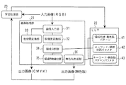
画像処理装置1の機能ブロックを図2に示す。図示のように、画像処理装置1は、画像処理部21、ルックアップテーブル(LUT)22、及び学習処理部23を有する。
<Functional block of image processing device>
A functional block of the
画像処理部21は画像入力部31、解像度変換部32、色空間変換部33、領域分割部34、領域特徴抽出部35、及び無色版生成部36を有する。ルックアップテーブル22は、領域特徴と無色版パターンとの関係を示す領域特徴−無色版パターンテーブル41、キーワードリストと領域分割パラメータとの関係を示すキーワード−領域分割パラメータテーブル42、及びキーワードリストと無色版パターンパラメータとの関係を示すキーワード−無色版パターンパラメータテーブル43を有する。なお、ルックアップテーブル22は記憶装置15または記憶装置5に保持されている。
The
画像入力部31に入力される入力画像は多くの場合RGBカラーで表現されるものであるが、プリンタやプロッタの色材の構成(例えばCMYK)に従って入力画像の色空間を変換する必要がある。これは色空間変換部33で行われる。
The input image input to the image input unit 31 is often expressed in RGB colors, but it is necessary to convert the color space of the input image according to the color material configuration of the printer or plotter (for example, CMYK). This is performed by the color
入力画像はまた、無色版作成の前処理として解像度変換や平滑化などの前処理を施される。これらの前処理は解像度変換部32にて行われる。前処理後の画像は予め定められた特徴により、領域分割を施される。これは領域分割部34で行われる処理であり、例えば文字領域と写真領域の抽出、写真領域に対するオブジェクト抽出などが行われる。このとき例えばユーザに操作装置16から領域分割パラメータを設定させることもできる。この場合ルックアップテーブル22から、キーワード−領域分割パラメータテーブル42を参照する。
The input image is also subjected to preprocessing such as resolution conversion and smoothing as preprocessing for creating a colorless plate. These preprocessing are performed by the resolution conversion unit 32. The preprocessed image is divided into regions according to predetermined characteristics. This is a process performed by the area dividing unit 34. For example, extraction of a character area and a photograph area, extraction of an object for the photograph area, and the like are performed. At this time, for example, the user can set the area division parameter from the
領域分割された入力画像を用いて各領域から領域特徴を算出する。この処理は領域特徴抽出部35で行われる。無色版生成部36は、領域特徴抽出部35で算出された領域特徴に対し、ルックアップテーブル22上の領域特徴−無色版パターンテーブル41を用いて各領域の無色版パターンを生成し出力画像(無色版)を得る。なお、学習処理部23については後述する。
A region feature is calculated from each region using the input image divided into regions. This processing is performed by the region feature extraction unit 35. The colorless plate generation unit 36 generates a colorless plate pattern for each region using the region feature-colorless plate pattern table 41 on the lookup table 22 for the region feature calculated by the region feature extraction unit 35 and outputs an output image ( Colorless version) is obtained. The
〈画像処理装置のコンポーネント〉
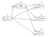
図3に本実施形態の画像形成システム(図1)のUMLコンポーネント図を示す。これらのコンポーネントは図1の画像処理装置1の記憶装置15で保持され、実行時にRAM14に展開される。
<Components of image processing device>
FIG. 3 shows a UML component diagram of the image forming system (FIG. 1) of the present embodiment. These components are held in the
図3に示すように、本実施形態の画像形成システムは、UMLコンポーネントとして、ユーザが直接操作するユーザインタフェース(User Interface)51、入力画像を分割し無色版を生成する領域分割器(Region segmenter)52、入力画像を取得するためのスキャナ(Scanner)53、画像保持のためのリポジトリ(Repository)54、印刷出力を行うためのプロッタ(Plotter)55からなる。
As shown in FIG. 3, the image forming system according to the present embodiment includes, as UML components, a user interface (User Interface) 51 that is directly operated by a user, and a region segmenter that divides an input image and generates a colorless plate. 52, a
ユーザインタフェース51はその他のコンポーネントに対する指示を行うため、オペレーション(operation)ポートに対してコネクションを持つ。領域分割器52はスキャナ53,リポジトリ54から情報を取得するために、データ(data)ポートに対してコネクションを持つ。また最終的な出力はリポジトリ54もしくはプロッタ55を経て行われるため、領域分割器52はこれらのコンポーネントに対してデータポートに出力用のコネクションも持つ。リポジトリ54は過去の画像データの他に、ルックアップテーブル22も保持する。
The
〈コンポーネントレベルでの基本的な動作〉
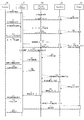
図4に各コンポーネントでの基本的な動作(振る舞い)のシーケンスを示す。
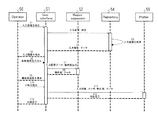
オペレータ(Operator)56はユーザインタフェース51を通じ入力画像を指示する(S1)。入力画像が既存の場合、例えば通常のファイルシステムにおける検索で得られる。これは図ではS2及びS3で示される。S3の入力画像検索で利用されるリポジトリ54は、HDDなどの記憶装置と、それを管理するコントローラ部、記憶内容を管理するコンテンツ管理部などからなるが、図ではそれらをまとめてリポジトリとしている。
<Basic operation at the component level>
FIG. 4 shows a basic operation (behavior) sequence in each component.
An
オペレータの指示によりリポジトリ54を検索し得られた入力画像は、確認のためユーザインタフェース51に表示される(S4、S5)。オペレータ56はユーザインタフェース51を通じて、表示された入力画像に対する無色版作成を指示する(S6)。
The input image obtained by searching the
領域分割器52はユーザインタフェース51から入力画像に関するデータを受け取る(S7)。これは例えばリポジトリ54内の特定のアドレスを指すポインタでもよいが、本実施形態では説明を簡単にするため、ユーザインタフェース51が入力画像を保持し、これを領域分割器52に渡すものとする。領域分割器52は与えられた入力画像を解析し、無色版を作製しユーザインタフェース51に返す(S8)。これも上記と同様に、領域分割器52がリポジトリ54に無色版を保存し、そのポインタをユーザインタフェース51に返すことでも実現できるが、本実施形態では説明を簡単にするため、ユーザインタフェース51が無色版を保持するものとする。
The
ユーザインタフェース51は作成された無色版をオペレータ56に表示する(S9)。オペレータ56は無色版を確認後、入力画像と無色版の印刷を指示する(S10)。
The
印刷工程は、ユーザインタフェース51が印刷に必要となる入力画像データと無色版データをプロッタ55に渡すことでなされる(S11)。プロッタ55は印刷を行うための機器である。ここでは電子写真記録方式によるプロッタ(プリンタ)とする。プロッタ55は、プロッタ全体の制御を行うコントローラ、印刷で利用されるトナー、トナーを紙面に転写する転写装置、転写されたトナーを紙面に定着させる定着装置、これら一連の処理を行うための紙搬送装置などからなる。プロッタ55は印刷が完了すると、ユーザインタフェース51を通してオペレータにその旨を通知する(S12、S13)。
The printing process is performed by the
上記過程で得られた無色版を利用することで、例えば電子写真プロセスでCMYKの4版に加え、無色版を紙面に印刷し、グロッサー(高温高圧による印刷表面処理機)を通すことで、高光沢効果が得られる。グロッサーの高温高圧により印刷表面が融解し、平坦になることで表面の平滑性が増すことによるものである。画像透かしなどの用途では、グロッサーを通さずに、クリアトナーに通常の印刷と同程度の光沢を与えるだけで済ませることもできる。 By using the colorless plate obtained in the above process, for example, in addition to the four plates of CMYK in the electrophotographic process, the colorless plate is printed on the paper surface and passed through a glosser (printing surface treatment machine with high temperature and high pressure). A gloss effect is obtained. This is because the smoothness of the surface is increased by melting and flattening the printing surface due to the high temperature and high pressure of the glosser. In applications such as image watermarking, it is possible to simply give the clear toner a gloss equivalent to that of normal printing without passing through the glosser.
本実施形態の画像処理装置1の主たる特徴は図4における領域分割器52及びユーザインタフェース51の動作(振る舞い)にある。以下この点について説明する。
〈領域分割器52の動作の第1の例〉
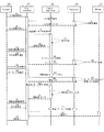
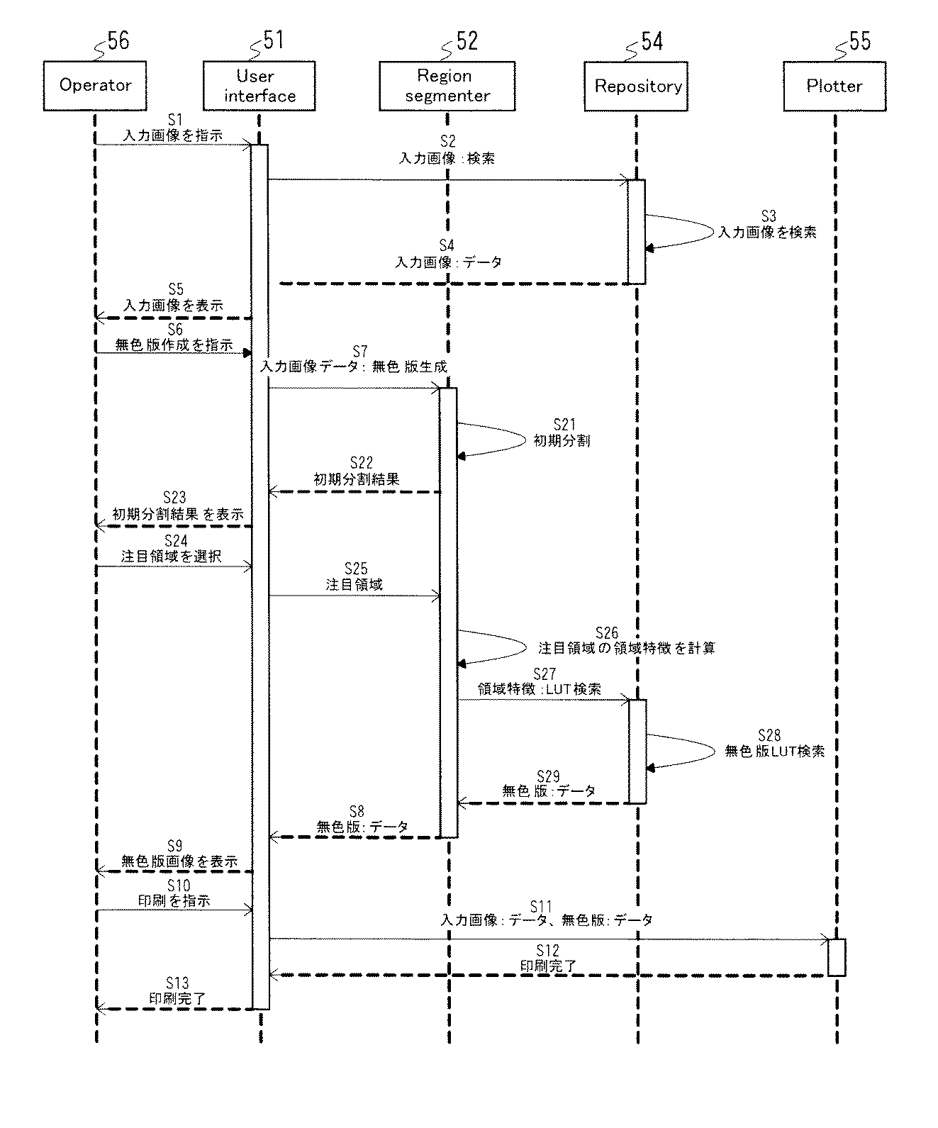
図5に領域分割器52の動作(振る舞い)の第1の例を示す。この図において、図4と同一又は対応するシーケンスには図4と同一の参照符号を付した。
The main feature of the
<First Example of Operation of
FIG. 5 shows a first example of the operation (behavior) of the
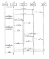
領域分割器52は、ユーザインタフェース51から入力画像に関するデータを受け取ると(S7)、その画像の特徴に基づいて画像の領域分割(初期分割)を行い(S21)、その結果をユーザインタフェース51によりオペレータ56に表示する(S22、S23)。
When the
オペレータ56がユーザインタフェース51に表示されている初期分割結果の画像から注目領域を選択すると(S24)、その選択された注目領域を示すデータが領域分割器52に渡される(S25)。
When the
領域分割器52は、受け取った領域の特徴を計算し(S26)、その領域特徴を用いてリポジトリ54内の領域特徴−無色版パターンテーブル41を検索し(S27、S28)、領域特徴に対応する無色版パターンを読み出す(S29)。以後のシーケンスは図4と同じである。
The
ここで、領域特徴−無色版パターンテーブル41のデータ構造としては例えば下記の表1のようなデータ構造を採用することができる。 Here, as the data structure of the region feature-colorless plate pattern table 41, for example, a data structure as shown in Table 1 below can be adopted.
この例では利用する特徴を領域内の画像の平均輝度と標準偏差の2つの組み合わせ(特徴セット)としたものである。また、平均輝度を3段階に分け、それぞれについて標準偏差を5段階に分けることで、15個の無色版パターンをポインタで指定できるようにした。なお、ルックアップテーブルで指定されたパターンはそれぞれ別途定義される。このパターンは記憶装置5又は記憶装置15で保持しておく。
In this example, the feature to be used is a combination (feature set) of the average luminance and the standard deviation of the image in the region. In addition, the average luminance is divided into three levels, and the standard deviation is divided into five levels for each, so that 15 colorless plate patterns can be designated with a pointer. Each pattern specified in the lookup table is defined separately. This pattern is held in the
このように、特徴セットとは、画像領域を特徴付ける指標の組みを指す。上述した(平均輝度、輝度標準偏差)の他には(平均輝度、平均色相、平均飽和度)が挙げられる。組みの中にある指標の数については1以上であれば良く、自由に決められるが、画像処理分野では、事前の試験により各処理に適切な指標の組みを見つけておくことが多い。 Thus, a feature set refers to a set of indices that characterize an image area. In addition to the above-described (average luminance, luminance standard deviation), (average luminance, average hue, average saturation) may be mentioned. The number of indicators in the set may be one or more and can be freely determined. However, in the image processing field, a set of indicators appropriate for each process is often found by a preliminary test.
3つ以上の特徴の組み合わせを用いる場合には、三次元以上のルックアップテーブルを作成する。実装上はルックアップテーブルに階層構造を持たせることで三次元以上のテーブルを容易に作成できる。 When a combination of three or more features is used, a three-dimensional or more lookup table is created. In terms of implementation, it is easy to create a three-dimensional table by providing a hierarchical structure for the lookup table.
〈領域分割器52の動作の第2の例〉
図6に領域分割器52の動作(振る舞い)の第2の例を示す。この図において、図5と同一又は対応のシーケンスには図5と同一の参照符号を付した。
<Second Example of Operation of
FIG. 6 shows a second example of the operation (behavior) of the
このシーケンス図の特徴はS30にある。S30は、オペレータ56がユーザインタフェース51に表示されている初期分割結果の注目領域及び以前に使用された無色版パターンを指定することで表1に示したようなテーブルを決定する手順である。
The feature of this sequence diagram is in S30. S30 is a procedure for determining the table as shown in Table 1 by designating the attention area of the initial division result displayed on the
即ちオペレータ56が注目領域の無色版パターンとして、以前に使用されたものを指定すると(S301)、領域分割器52は指定された無色版パターンをリポジトリ54から検索し、読み出す(S302、S303、S304)。そして、読み出された無色版パターンを解析して、平均輝度と標準偏差を算出する。この手順を初期分割された全ての領域に対して繰り返すことで、平均輝度と標準偏差からなる特徴セットと、以前に使用された無色版パターンとの関係を示すテーブルを決定することができる。
That is, when the
このように、各初期分割領域に対してオペレータ56が無色版パターンを指定するようなトライアルを行い、その結果を解析することで、例えば表1のような各領域の平均輝度と標準偏差に対して、過去の一例として無色版パターンを指定することができる。
Thus, by performing a trial in which the
また、図6のS30により、表1のようなテーブルの内容を、以前の入力データと、そこから生成された無色版パターンとの対応関係から学習することにより作成することもできる。この場合、各初期分割領域に対して、オペレータに過去の複数の無色版パターンを手動で選択させ、その結果を基にサポートベクターマシンなどを用いて学習処理部23で学習し、ルックアップテーブル22で利用する。つまり、単純に過去の一例をそのまま用いるのではなく、過去の複数の例に基づいて予め定めておいた代表値(平均値など)を用いて、ルックアップテーブルを決定する。
6 can be created by learning the contents of the table as shown in Table 1 from the correspondence between the previous input data and the colorless plate pattern generated therefrom. In this case, for each initial divided region, the operator manually selects a plurality of past colorless plate patterns, and the
〈ユーザインタフェース51の動作の第1の例〉
図7にユーザインタフェース51の動作(振る舞い)の第1の例を示す。この図において、図5と同一又は対応するシーケンスには図5と同一の参照符号を付した。
<First Example of Operation of
FIG. 7 shows a first example of the operation (behavior) of the
この図のシーケンスは、ユーザが容易に理解できるキーワードリストをリポジトリ54に用意しておき、ユーザにキーワードリストを表示し、キーワードを選択させることで、キーワードに応じた初期分割を行うことが特徴である。
The sequence shown in this figure is characterized in that a keyword list that can be easily understood by the user is prepared in the
図7に示すように、オペレータ56がユーザインタフェース51を通じて無色版作成を指示すると(S6)、領域分割器52はリポジトリ54からキーワードリストを検索し(S31、S32)、ユーザインタフェース51を通じてオペレータ56に表示する(S33、S34)。
As shown in FIG. 7, when the
オペレータ56がキーワードリスト中の所望のキーワードを選択すると(S35)、ユーザインタフェース51はそのキーワードをクエリとしてリポジトリ54内のキーワード−領域分割パラメータテーブル42を検索して(S36、S37)、キーワードに対応する特徴リストを読み出し、ユーザインタフェース51に渡す(S38)。
When the
下記の表2にキーワード−領域分割パラメータテーブル42の内容の一例を示す。このテーブルには、キーワードリストとして「大まかに」、「詳細に」などが書かれており、領域分割パラメータの特徴として「入力画像低解像度化倍率3」、「入力画像低解像度化倍率1」などが書かれている。なお、表2は1つのキーワードに対して、1つの特徴が対応する例であるが、1つのキーワードに対して複数の特徴を対応させる(特徴リストとする)こともできる。
Table 2 below shows an example of the contents of the keyword-region division parameter table 42. In this table, “roughly”, “detailed”, etc. are written as a keyword list, and “input image low
次いでユーザインタフェース51は、領域分割器52に対して、入力画像データ、特徴リストを渡し、無色版の生成を指示する(S39)。領域分割器52は、入力された特徴リストに応じて、入力画像の初期分割を行う(S21)。以後の手順は図5と同じである。
Next, the
〈ユーザインタフェース51の動作の第2の例〉
図8にユーザインタフェース51の動作(振る舞い)の第2の例を示す。この図において、図5と同一又は対応するシーケンスには図5と同一の参照符号を付した。
<Second Example of Operation of
FIG. 8 shows a second example of the operation (behavior) of the
この図のシーケンスは、ユーザが容易に理解できるキーワードリスト(ざらざら、すべすべ、メリハリがきいている等)をリポジトリ54に用意しておき、ユーザにキーワードリストを表示し、キーワードを選択させることで、キーワードに応じた無色版パターンを生成することが特徴である。
In the sequence of this figure, a keyword list that can be easily understood by the user (rough, smooth, sharp, etc.) is prepared in the
図8に示すように、オペレータ56が注目領域を選択すると(S24)、ユーザインタフェース51はリポジトリ54内のキーワードリストを検索し(S41、S42)、検索したキーワードリストを、ユーザインタフェース51を通してオペレータ56に表示する(S43、S44)。
As shown in FIG. 8, when the
オペレータ56がキーワードリスト中の所望のキーワードを選択すると(S45)、ユーザインタフェース51はそのキーワードをクエリとしてリポジトリ54内のキーワード−無色版パターンパラメータテーブル43を検索して(S46、S47)、キーワードに対応する特徴リストを読み出し、ユーザインタフェース51に渡す(S48)。特徴リストとしては万線とその周波数、あるいは網点とその比率などが挙げられる。
When the
次いでユーザインタフェース51は、領域分割器52に対して、特徴リストを渡し、無色版の生成を指示する(S49)。領域分割器52は、入力された特徴リストに応じて、無色版を生成する(S50)。以後の手順は図5と同じである。
Next, the
なお、以上の実施形態では、オペレータは、表示された無色版をそのまま用いているが、適宜修正して用いることもできる。また、以上の実施形態は画像形成装置に用いる無色版の作成に関するものであるが、本発明は画像の領域に対する無色版パターンを定めることに関するものであり、印刷プロセスには依存しない。従って、本発明はオフセット印刷用の無色版(ニス版)の作成にも適用することができる。 In the above embodiment, the operator uses the displayed colorless plate as it is. However, the operator can appropriately modify and use it. The above embodiment relates to the production of a colorless plate for use in an image forming apparatus. However, the present invention relates to defining a colorless plate pattern for an image area and does not depend on the printing process. Therefore, the present invention can also be applied to the production of a colorless plate (varnish plate) for offset printing.
[第2の実施形態]
図9は、本発明の第2の実施形態の画像処理装置の無色版パターン生成処理のフローチャートである。本実施形態の画像処理装置を有する画像形成システム、本実施形態の画像処理装置の機能ブロック図、本実施形態の画像処理装置を含む画像形成システムのUMLコンポーネント図、その各コンポーネントの基本的な動作を示すシーケンス図は、それぞれ第1の実施形態の図1、図2、図3、図4と同じである。
[Second Embodiment]
FIG. 9 is a flowchart of the colorless plate pattern generation process of the image processing apparatus according to the second embodiment of the present invention. Image forming system having image processing apparatus of this embodiment, functional block diagram of image processing apparatus of this embodiment, UML component diagram of image forming system including image processing apparatus of this embodiment, and basic operation of each component The sequence diagrams showing are the same as FIGS. 1, 2, 3, and 4 of the first embodiment, respectively.
図9は、第1の実施形態の図5のシーケンスを、パイルハイト制約条件及び紙種情報を読み込み、それらを加味して、無色版パターンを決定するように変形する処理と言える。即ちステップST101の画像入力処理は図5のシーケンスS1に対応し、ステップST102の領域指定処理は図5のシーケンスS24に対応する。また、ステップST104のパイルハイト制約条件読み込み処理、ステップST105の紙種情報読み込み処理、ステップST106の無色版パターン決定処理は、図5のシーケンスS27〜S29に対応する。ここで、ステップST104で読み込まれるパイルハイト制約条件、ステップST105で読み込まれる紙種情報は、予め定められ図3のレポジトリ54により保持されている。なお、ステップST103の領域選択処理、ステップST107の判定処理、及びステップST108の次の領域を選択する処理は、複数の領域指定を可能にするために設けた処理である。
FIG. 9 can be said to be a process in which the sequence of FIG. 5 of the first embodiment is modified to read the pile height constraint condition and the paper type information and take them into consideration to determine the colorless plate pattern. That is, the image input process in step ST101 corresponds to the sequence S1 in FIG. 5, and the area designation process in step ST102 corresponds to the sequence S24 in FIG. Further, the pile height constraint condition reading process in step ST104, the paper type information reading process in step ST105, and the colorless plate pattern determination process in step ST106 correspond to the sequences S27 to S29 in FIG. Here, the pile height restriction condition read in step ST104 and the paper type information read in step ST105 are determined in advance and held in the
ただし、図5のシーケンスS27〜S29では、前述のとおり、領域特徴(平均輝度、標準偏差)を用いてリポジトリ54内の領域特徴−無色版パターンテーブル41(表1参照)を検索し(S27、S28)、領域特徴に対応する無色版パターンを読み出す(S29)のに対し、本実施形態では、領域特徴(平均輝度、標準偏差)に加え、パイルハイト制約条件及び紙種情報を用いて、リポジトリ54内の領域特徴・パイルハイト制約条件・紙種情報−無色版パターンテーブルを検索し、対応する無色版パターンを読み出す。
However, in the sequences S27 to S29 of FIG. 5, as described above, the region feature-colorless plate pattern table 41 (see Table 1) in the
領域特徴・パイルハイト制約条件・紙種情報−無色版パターンテーブルは、例えば表1に示す領域特徴−無色版パターンテーブル41を、パイルハイト制約条件毎、紙種毎に設けることで実現できる。このテーブルを用いることで、電子写真プロセスに利用する無色版パターンについて、パイルハイト制約条件及び紙種を考慮した無色版パターンを生成することができる。 The region feature / pile height constraint condition / paper type information-colorless plate pattern table can be realized by providing, for example, the region feature-colorless plate pattern table 41 shown in Table 1 for each pile height constraint condition and for each paper type. By using this table, it is possible to generate a colorless plate pattern in consideration of the pile height constraint condition and the paper type for the colorless plate pattern used in the electrophotographic process.
パイルハイト制約条件としては、定着ローラーのニップ幅、定着温度、トナー種類のいずれか一つもしくは二つ以上の組み合わせを用いる。また、紙種情報としては、紙の重さ、紙の白色度、紙の光沢度、紙の表面平滑度のいずれか一つもしくは二つ以上の組み合わせを用いる。 As the pile height constraint condition, one or a combination of two or more of the nip width of the fixing roller, the fixing temperature, and the toner type is used. As the paper type information, one or a combination of two or more of paper weight, paper whiteness, paper glossiness, and paper surface smoothness is used.
なお、以上の説明では、領域特徴に加えて、パイルハイト制約条件、紙種情報の双方を用いるものとしたが、領域特徴に加えて、パイルハイト制約条件のみを用い、紙種情報を用いなくてもよい。 In the above description, in addition to the region feature, both the pile height constraint condition and the paper type information are used. However, in addition to the region feature, only the pile height constraint condition is used and the paper type information is not used. Good.
1…画像処理装置、21…画像処理部、22…ルックアップテーブル、23…学習処理部、34…領域分割部、35…領域特徴抽出部、36…無色版生成部、41…領域特徴−無色版パターンテーブル、42…キーワード−領域分割パラメータテーブル、43…キーワード−無色版パターンパラメータテーブル。
DESCRIPTION OF
Claims (12)
その領域分割部により分割された領域の特徴を求める特徴抽出部と、
予め定められた画像の特徴と無色版パターンとの対応関係を保持するルックアップテーブルと、
前記特徴抽出部により求められた特徴を用いて前記ルックアップテーブルを参照し、その特徴に対応する無色版パターンを決定し、その無色版パターンを用いて無色版を生成する無色版生成部と
を有することを特徴とする画像処理装置。 An area dividing unit that divides the input image into a plurality of areas based on the content of the image;
A feature extraction unit for obtaining features of the region divided by the region division unit;
A look-up table that retains the correspondence between predetermined image features and colorless plate patterns;
A colorless plate generating unit that refers to the lookup table using the feature obtained by the feature extracting unit, determines a colorless plate pattern corresponding to the feature, and generates a colorless plate using the colorless plate pattern; An image processing apparatus comprising:
前記ルックアップテーブルの内容が、以前の入力画像で用いられた無色版パターンにより構成されていることを特徴とする画像処理装置。 The image processing apparatus according to claim 1,
The image processing apparatus according to claim 1, wherein the contents of the look-up table are constituted by a colorless plate pattern used in a previous input image.
前記ルックアップテーブルの内容が、以前の入力画像における領域と、該領域に対して付与された無色版パターンとの関係を用いて学習されたものであることを特徴とする画像処理装置。 The image processing apparatus according to claim 1,
An image processing apparatus, wherein the contents of the lookup table are learned using a relationship between a region in a previous input image and a colorless plate pattern assigned to the region.
予め定められたキーワードリストと領域分割パラメータとの対応関係を保持するルックアップテーブルと、該キーワードリストを表示する手段とを有するとともに、前記領域分割部は、該ユーザにより選択されたキーワードに関連付けられた領域分割パラメータを用いて、入力画像の領域分割を行うことを特徴とする画像処理装置。 The image processing apparatus according to claim 1,
A lookup table that holds a correspondence relationship between a predetermined keyword list and an area division parameter; and a means for displaying the keyword list. The area division unit is associated with a keyword selected by the user. An image processing apparatus that performs region division of an input image using the region division parameter.
予め定められたキーワードリストと無色版パターンを生成するためのパラメータとの対応関係を保持するルックアップテーブルと、該キーワードリストを表示する手段とを有するとともに、前記無色版生成部は、該ユーザにより選択されたキーワードに関連付けられた無色版パターン生成パラメータを用いて、入力画像に対して無色版パターンを生成することを特徴とする画像処理装置。 The image processing apparatus according to claim 1,
A look-up table that holds a correspondence relationship between a predetermined keyword list and a parameter for generating a colorless plate pattern; and a means for displaying the keyword list. An image processing apparatus that generates a colorless plate pattern for an input image using a colorless plate pattern generation parameter associated with a selected keyword.
前記ルックアップテーブルは、予め定められた画像の特徴、及び予め定められた電子写真プロセスの定着処理におけるパイルハイト制約条件と無色版パターンとの対応関係を保持するものであり、
前記無色版生成部は、前記特徴抽出部により求められた特徴及び前記パイルハイト制約条件を用いて、前記ルックアップテーブルを参照し、その特徴及びパイルハイト制約条件に対応する無色版パターンを決定し、その無色版パターンを用いて無色版を生成する
ことを特徴とする画像処理装置。 The image processing apparatus according to claim 1,
The look-up table holds a correspondence between a predetermined image characteristic and a pile height constraint condition and a colorless plate pattern in a fixing process of a predetermined electrophotographic process,
The colorless plate generation unit determines the colorless plate pattern corresponding to the feature and the pile height constraint condition by referring to the lookup table using the feature obtained by the feature extraction unit and the pile height constraint condition, An image processing apparatus that generates a colorless plate using a colorless plate pattern.
前記ルックアップテーブルは、予め定められた画像の特徴、予め定められた電子写真プロセスの定着処理におけるパイルハイト制約条件、及び前記電子写真プロセスにより画像が形成される紙の紙種情報と無色版パターンとの対応関係を保持するものであり、
前記無色版生成部は、前記特徴抽出部により求められた特徴、前記パイルハイト制約条件、及び前記紙種情報を用いて、前記ルックアップテーブルを参照し、その特徴、パイルハイト制約条件、及び紙種情報に対応する無色版パターンを決定し、その無色版パターンを用いて無色版を生成する
ことを特徴とする画像処理装置。 The image processing apparatus according to claim 6, wherein
The look-up table includes predetermined image characteristics, pile height constraint conditions in fixing processing of a predetermined electrophotographic process, paper type information of a paper on which an image is formed by the electrophotographic process, and a colorless plate pattern Of the correspondence of
The colorless plate generation unit refers to the look-up table using the feature obtained by the feature extraction unit, the pile height constraint condition, and the paper type information, and the feature, the pile height constraint condition, and the paper type information. An image processing apparatus, comprising: determining a colorless plate pattern corresponding to 1 and generating a colorless plate using the colorless plate pattern.
前記パイルハイト制約条件は、ニップ幅、定着温度、トナー種類のいずれか一つもしくは二つ以上の組み合わせであることを特徴とする画像処理装置。 The image processing apparatus according to claim 6, wherein
The image processing apparatus according to claim 1, wherein the pile height constraint condition is one or a combination of two or more of a nip width, a fixing temperature, and a toner type.
前記紙種情報は、紙の重さ情報、光沢度情報、白色度情報、表面平滑度情報のいずれか一つもしくは二つ以上の組み合わせであることを特徴とする画像処理装置。 The image processing device according to claim 7,
The image processing apparatus, wherein the paper type information is any one or a combination of two or more of paper weight information, gloss information, whiteness information, and surface smoothness information.
前記領域分割部により分割された領域のうち、ユーザにより指定された領域を選択する領域選択部を有し、
前記特徴抽出部は、該領域選択部により選択された領域のみの特徴を抽出する
ことを特徴とする画像処理装置。 The image processing apparatus according to claim 1,
Among the areas divided by the area dividing unit, an area selecting unit that selects an area specified by the user,
The feature extraction unit extracts features of only the region selected by the region selection unit.
前記領域の特徴は、輝度の平均値及び標準偏差であることを特徴とする画像処理装置。 The image processing apparatus according to claim 1,
The image processing apparatus characterized in that the characteristics of the region are an average value and a standard deviation of luminance.
Priority Applications (4)
| Application Number | Priority Date | Filing Date | Title |
|---|---|---|---|
| JP2010160612A JP5531836B2 (en) | 2009-11-10 | 2010-07-15 | Image processing apparatus and program |
| EP10251866.9A EP2320635B1 (en) | 2009-11-10 | 2010-10-28 | Apparatus, system, and method of image processing |
| US12/917,628 US8571316B2 (en) | 2009-11-10 | 2010-11-02 | Electrophotographic apparatus, system, and method of using colorless toner |
| CN201010536993.6A CN102053807B (en) | 2009-11-10 | 2010-11-04 | Image processing apparatus and image processing method |
Applications Claiming Priority (3)
| Application Number | Priority Date | Filing Date | Title |
|---|---|---|---|
| JP2009256990 | 2009-11-10 | ||
| JP2009256990 | 2009-11-10 | ||
| JP2010160612A JP5531836B2 (en) | 2009-11-10 | 2010-07-15 | Image processing apparatus and program |
Publications (3)
| Publication Number | Publication Date |
|---|---|
| JP2011123473A true JP2011123473A (en) | 2011-06-23 |
| JP2011123473A5 JP2011123473A5 (en) | 2013-06-27 |
| JP5531836B2 JP5531836B2 (en) | 2014-06-25 |
Family
ID=43629706
Family Applications (1)
| Application Number | Title | Priority Date | Filing Date |
|---|---|---|---|
| JP2010160612A Active JP5531836B2 (en) | 2009-11-10 | 2010-07-15 | Image processing apparatus and program |
Country Status (4)
| Country | Link |
|---|---|
| US (1) | US8571316B2 (en) |
| EP (1) | EP2320635B1 (en) |
| JP (1) | JP5531836B2 (en) |
| CN (1) | CN102053807B (en) |
Cited By (10)
| Publication number | Priority date | Publication date | Assignee | Title |
|---|---|---|---|---|
| JP2013166321A (en) * | 2012-02-16 | 2013-08-29 | Seiko Epson Corp | Image forming apparatus and image forming method |
| JP2013166322A (en) * | 2012-02-16 | 2013-08-29 | Seiko Epson Corp | Image forming apparatus and image forming method |
| JP2013182027A (en) * | 2012-02-29 | 2013-09-12 | Ricoh Co Ltd | Image forming apparatus, image forming method, program, and recording medium |
| JP2013205682A (en) * | 2012-03-29 | 2013-10-07 | Konica Minolta Inc | Image forming apparatus and image forming method |
| US8804194B2 (en) | 2012-03-29 | 2014-08-12 | Konica Minolta Business Technologies, Inc. | Image forming apparatus and image forming method |
| JP2014171219A (en) * | 2013-02-28 | 2014-09-18 | Ricoh Co Ltd | Mechanism for top coat processing |
| US9083920B2 (en) | 2012-04-11 | 2015-07-14 | Ricoh Company, Limited | Information processing apparatus, information processing system, information processing method, and computer-readable storage medium that assign priority information indicating priority between areas in an overlapping area |
| US9110426B2 (en) | 2010-09-15 | 2015-08-18 | Ricoh Company, Limited | Information processing apparatus, data generation method, and data structure |
| US9342026B2 (en) | 2010-09-15 | 2016-05-17 | Ricoh Company, Limited | Print control apparatus, image forming system, print control method, and printed-matter manufacturing method |
| JP2018004897A (en) * | 2016-06-30 | 2018-01-11 | 京セラドキュメントソリューションズ株式会社 | Image formation apparatus |
Families Citing this family (9)
| Publication number | Priority date | Publication date | Assignee | Title |
|---|---|---|---|---|
| US8619329B2 (en) * | 2010-11-12 | 2013-12-31 | Xerox Corporation | Print smoothness on clear toner enabled systems |
| JP5849522B2 (en) | 2011-08-18 | 2016-01-27 | 株式会社リコー | Image processing apparatus, projector, projector system, image processing method, program thereof, and recording medium recording the program |
| JP2013196308A (en) | 2012-03-19 | 2013-09-30 | Ricoh Co Ltd | Image processor, image processing method, program and recording medium |
| US9158504B2 (en) * | 2012-10-12 | 2015-10-13 | Baker Hughes Incorporated | Method and system to automatically generate use case sequence diagrams and class diagrams |
| JP2014164656A (en) | 2013-02-27 | 2014-09-08 | Ricoh Co Ltd | Image processing method and program |
| JP6541417B2 (en) * | 2015-05-12 | 2019-07-10 | キヤノン株式会社 | Image processing apparatus, image forming apparatus, image processing method and program |
| JP2017049742A (en) * | 2015-09-01 | 2017-03-09 | キヤノン株式会社 | Image processing method, image processing apparatus, robot apparatus, program and recording medium |
| US10198626B2 (en) * | 2016-10-19 | 2019-02-05 | Snap Inc. | Neural networks for facial modeling |
| US10861137B2 (en) * | 2017-09-15 | 2020-12-08 | Canon Kabushiki Kaisha | Image processing apparatus, image processing method, and storage medium |
Citations (17)
| Publication number | Priority date | Publication date | Assignee | Title |
|---|---|---|---|---|
| JPH1055085A (en) * | 1996-08-08 | 1998-02-24 | Fuji Xerox Co Ltd | Color image forming device |
| JPH1055089A (en) * | 1996-08-08 | 1998-02-24 | Fuji Xerox Co Ltd | Color image forming device |
| JPH10126630A (en) * | 1996-10-14 | 1998-05-15 | Canon Inc | Image processing device |
| JP2001305806A (en) * | 2000-04-24 | 2001-11-02 | Sharp Corp | Image forming device |
| JP2002331708A (en) * | 2001-05-09 | 2002-11-19 | Canon Inc | Printing system, printing method of printing system, image processing apparatus, processing method of image processing apparatus, and storage medium |
| JP2003087591A (en) * | 2001-09-14 | 2003-03-20 | Canon Inc | Image processing method and image processing apparatus |
| JP2006115359A (en) * | 2004-10-15 | 2006-04-27 | Sharp Corp | Image processing device |
| JP2007139988A (en) * | 2005-11-16 | 2007-06-07 | Kyocera Mita Corp | Image forming apparatus |
| JP2007199291A (en) * | 2006-01-25 | 2007-08-09 | Fuji Xerox Co Ltd | Image processing device and image forming apparatus |
| JP2007281884A (en) * | 2006-04-06 | 2007-10-25 | Canon Inc | Image processing method and apparatus |
| JP2009055601A (en) * | 2007-07-31 | 2009-03-12 | Canon Inc | Control device, control method, program, and recording medium |
| JP2009058941A (en) * | 2007-08-03 | 2009-03-19 | Canon Inc | Image forming system |
| JP2009068891A (en) * | 2007-09-11 | 2009-04-02 | Ricoh Co Ltd | Reflected light detection apparatus, image characteristic measurement apparatus, and image forming apparatus |
| JP2009151238A (en) * | 2007-12-21 | 2009-07-09 | Canon Inc | Image forming apparatus |
| JP2009181045A (en) * | 2008-01-31 | 2009-08-13 | Canon Inc | Image forming apparatus, image forming method, recording medium, and program |
| JP2009253956A (en) * | 2008-04-11 | 2009-10-29 | Canon Inc | Image processing apparatus |
| JP2010102032A (en) * | 2008-10-22 | 2010-05-06 | Canon Inc | Copying apparatus |
Family Cites Families (12)
| Publication number | Priority date | Publication date | Assignee | Title |
|---|---|---|---|---|
| JP3185859B2 (en) * | 1997-07-24 | 2001-07-11 | 富士ゼロックス株式会社 | Image processing apparatus and image forming apparatus |
| US6863374B2 (en) * | 2002-04-16 | 2005-03-08 | Seiko Epson Corporation | Image printing using print quality enhancing ink |
| JP4561103B2 (en) * | 2004-01-16 | 2010-10-13 | コニカミノルタエムジー株式会社 | Inkjet recording device |
| US7212772B2 (en) | 2005-02-22 | 2007-05-01 | Eastman Kodak Company | System and method for creating a three-dimensional texture in an electrophotographic image |
| US7236734B2 (en) * | 2005-02-22 | 2007-06-26 | Eastman Kodak Company | Method and apparatus for electrostatographic printing with enhanced color gamut |
| WO2007045277A1 (en) * | 2005-10-20 | 2007-04-26 | Hewlett-Packard Development Company, L.P. | Printing and printers |
| JP4816160B2 (en) * | 2006-03-10 | 2011-11-16 | コニカミノルタホールディングス株式会社 | Image recording apparatus, image recording method, and image recording program |
| CN101119429A (en) | 2006-08-01 | 2008-02-06 | 北京北大方正电子有限公司 | A method and device for digital watermark embedding and extraction |
| JP2008145453A (en) | 2006-12-05 | 2008-06-26 | Canon Inc | Image forming system and image forming apparatus |
| US8356883B2 (en) * | 2008-02-06 | 2013-01-22 | Eastman Kodak Company | Inkjet printing method for colorless ink using colorless ink printhead masks dependent on colored ink printing |
| JP5129006B2 (en) | 2008-04-18 | 2013-01-23 | シロキ工業株式会社 | Pinching detection method and apparatus |
| JP5172717B2 (en) | 2009-01-07 | 2013-03-27 | 株式会社エヌ・ティ・ティ・データ | Voting anticipation disclosure system and method, and computer program |
-
2010
- 2010-07-15 JP JP2010160612A patent/JP5531836B2/en active Active
- 2010-10-28 EP EP10251866.9A patent/EP2320635B1/en active Active
- 2010-11-02 US US12/917,628 patent/US8571316B2/en active Active
- 2010-11-04 CN CN201010536993.6A patent/CN102053807B/en active Active
Patent Citations (17)
| Publication number | Priority date | Publication date | Assignee | Title |
|---|---|---|---|---|
| JPH1055085A (en) * | 1996-08-08 | 1998-02-24 | Fuji Xerox Co Ltd | Color image forming device |
| JPH1055089A (en) * | 1996-08-08 | 1998-02-24 | Fuji Xerox Co Ltd | Color image forming device |
| JPH10126630A (en) * | 1996-10-14 | 1998-05-15 | Canon Inc | Image processing device |
| JP2001305806A (en) * | 2000-04-24 | 2001-11-02 | Sharp Corp | Image forming device |
| JP2002331708A (en) * | 2001-05-09 | 2002-11-19 | Canon Inc | Printing system, printing method of printing system, image processing apparatus, processing method of image processing apparatus, and storage medium |
| JP2003087591A (en) * | 2001-09-14 | 2003-03-20 | Canon Inc | Image processing method and image processing apparatus |
| JP2006115359A (en) * | 2004-10-15 | 2006-04-27 | Sharp Corp | Image processing device |
| JP2007139988A (en) * | 2005-11-16 | 2007-06-07 | Kyocera Mita Corp | Image forming apparatus |
| JP2007199291A (en) * | 2006-01-25 | 2007-08-09 | Fuji Xerox Co Ltd | Image processing device and image forming apparatus |
| JP2007281884A (en) * | 2006-04-06 | 2007-10-25 | Canon Inc | Image processing method and apparatus |
| JP2009055601A (en) * | 2007-07-31 | 2009-03-12 | Canon Inc | Control device, control method, program, and recording medium |
| JP2009058941A (en) * | 2007-08-03 | 2009-03-19 | Canon Inc | Image forming system |
| JP2009068891A (en) * | 2007-09-11 | 2009-04-02 | Ricoh Co Ltd | Reflected light detection apparatus, image characteristic measurement apparatus, and image forming apparatus |
| JP2009151238A (en) * | 2007-12-21 | 2009-07-09 | Canon Inc | Image forming apparatus |
| JP2009181045A (en) * | 2008-01-31 | 2009-08-13 | Canon Inc | Image forming apparatus, image forming method, recording medium, and program |
| JP2009253956A (en) * | 2008-04-11 | 2009-10-29 | Canon Inc | Image processing apparatus |
| JP2010102032A (en) * | 2008-10-22 | 2010-05-06 | Canon Inc | Copying apparatus |
Cited By (12)
| Publication number | Priority date | Publication date | Assignee | Title |
|---|---|---|---|---|
| US9110426B2 (en) | 2010-09-15 | 2015-08-18 | Ricoh Company, Limited | Information processing apparatus, data generation method, and data structure |
| US9342026B2 (en) | 2010-09-15 | 2016-05-17 | Ricoh Company, Limited | Print control apparatus, image forming system, print control method, and printed-matter manufacturing method |
| US9575454B2 (en) | 2010-09-15 | 2017-02-21 | Ricoh Company, Ltd. | Information processing apparatus generating gloss control data |
| US9977391B2 (en) | 2010-09-15 | 2018-05-22 | Ricoh Company, Ltd. | Print control apparatus, image forming system, print control method, and printed-matter manufacturing method |
| JP2013166321A (en) * | 2012-02-16 | 2013-08-29 | Seiko Epson Corp | Image forming apparatus and image forming method |
| JP2013166322A (en) * | 2012-02-16 | 2013-08-29 | Seiko Epson Corp | Image forming apparatus and image forming method |
| JP2013182027A (en) * | 2012-02-29 | 2013-09-12 | Ricoh Co Ltd | Image forming apparatus, image forming method, program, and recording medium |
| JP2013205682A (en) * | 2012-03-29 | 2013-10-07 | Konica Minolta Inc | Image forming apparatus and image forming method |
| US8804194B2 (en) | 2012-03-29 | 2014-08-12 | Konica Minolta Business Technologies, Inc. | Image forming apparatus and image forming method |
| US9083920B2 (en) | 2012-04-11 | 2015-07-14 | Ricoh Company, Limited | Information processing apparatus, information processing system, information processing method, and computer-readable storage medium that assign priority information indicating priority between areas in an overlapping area |
| JP2014171219A (en) * | 2013-02-28 | 2014-09-18 | Ricoh Co Ltd | Mechanism for top coat processing |
| JP2018004897A (en) * | 2016-06-30 | 2018-01-11 | 京セラドキュメントソリューションズ株式会社 | Image formation apparatus |
Also Published As
| Publication number | Publication date |
|---|---|
| EP2320635B1 (en) | 2017-09-20 |
| EP2320635A3 (en) | 2012-10-24 |
| JP5531836B2 (en) | 2014-06-25 |
| US20110110590A1 (en) | 2011-05-12 |
| US8571316B2 (en) | 2013-10-29 |
| CN102053807B (en) | 2013-12-18 |
| CN102053807A (en) | 2011-05-11 |
| EP2320635A2 (en) | 2011-05-11 |
Similar Documents
| Publication | Publication Date | Title |
|---|---|---|
| JP5531836B2 (en) | Image processing apparatus and program | |
| US8599406B2 (en) | Image forming apparatus, printing method and printing program for receiving an image from a server via a network and printing the image corresponding to area displayed on display unit to correspond to a user's designated sheet size | |
| US20160241743A1 (en) | Image processing system, image processing apparatus, and image forming apparatus | |
| US10078476B2 (en) | Image forming apparatus and image forming method | |
| JP5845797B2 (en) | Image processing apparatus, image processing method, and program | |
| JP2010272049A (en) | Image processor, image processing program, image processing method, and image forming device | |
| JP5077105B2 (en) | Image processing apparatus, image processing program, and image processing system | |
| JP2010157220A (en) | Variable data printing method using variable text color depending on background | |
| CN101848298B (en) | Image-processing device, image-forming device, image-processing method | |
| JP4946541B2 (en) | Color conversion processing program, color conversion processing device, and image forming system | |
| JP7094092B2 (en) | Information processing equipment, information processing system, control program and control method | |
| JP2011034268A (en) | Printer driver, printer, and printing method | |
| JP5420996B2 (en) | Variable data printing method using different printers for different contents | |
| JP2017167630A (en) | Search device and program | |
| JP6508135B2 (en) | Advertisement output device and advertisement output program | |
| JP2006185321A (en) | Printing condition judgment method | |
| JP5744588B2 (en) | Image processing apparatus and image processing system | |
| JP6394573B2 (en) | Information output device and information output program | |
| JP2015215456A (en) | Image processing apparatus, information processing method, and program | |
| JP4665981B2 (en) | Image processing method, image processing program, and image processing apparatus | |
| JP6394574B2 (en) | Information output device and information output program | |
| JP2011062921A (en) | Image forming apparatus and program | |
| JP5452804B2 (en) | Image forming apparatus | |
| JP2021052261A (en) | Image forming apparatus | |
| JP2013210861A (en) | Image forming system, image forming apparatus, control method of the same, and program |
Legal Events
| Date | Code | Title | Description |
|---|---|---|---|
| A521 | Request for written amendment filed |
Free format text: JAPANESE INTERMEDIATE CODE: A523 Effective date: 20130510 |
|
| A621 | Written request for application examination |
Free format text: JAPANESE INTERMEDIATE CODE: A621 Effective date: 20130510 |
|
| A977 | Report on retrieval |
Free format text: JAPANESE INTERMEDIATE CODE: A971007 Effective date: 20131211 |
|
| A131 | Notification of reasons for refusal |
Free format text: JAPANESE INTERMEDIATE CODE: A131 Effective date: 20140107 |
|
| A521 | Request for written amendment filed |
Free format text: JAPANESE INTERMEDIATE CODE: A523 Effective date: 20140310 |
|
| TRDD | Decision of grant or rejection written | ||
| A01 | Written decision to grant a patent or to grant a registration (utility model) |
Free format text: JAPANESE INTERMEDIATE CODE: A01 Effective date: 20140325 |
|
| A61 | First payment of annual fees (during grant procedure) |
Free format text: JAPANESE INTERMEDIATE CODE: A61 Effective date: 20140407 |
|
| R151 | Written notification of patent or utility model registration |
Ref document number: 5531836 Country of ref document: JP Free format text: JAPANESE INTERMEDIATE CODE: R151 |