JP2011123737A - Object recognition device, object recognition method, and program - Google Patents
Object recognition device, object recognition method, and program Download PDFInfo
- Publication number
- JP2011123737A JP2011123737A JP2009281747A JP2009281747A JP2011123737A JP 2011123737 A JP2011123737 A JP 2011123737A JP 2009281747 A JP2009281747 A JP 2009281747A JP 2009281747 A JP2009281747 A JP 2009281747A JP 2011123737 A JP2011123737 A JP 2011123737A
- Authority
- JP
- Japan
- Prior art keywords
- value
- image
- template image
- partial image
- total
- Prior art date
- Legal status (The legal status is an assumption and is not a legal conclusion. Google has not performed a legal analysis and makes no representation as to the accuracy of the status listed.)
- Granted
Links
Images



Landscapes
- Image Analysis (AREA)
Abstract
【課題】被探索画像の一部分に短期的及び長期的な輝度変動が起っても、物体の認識精度を向上させる。
【解決手段】テンプレート画像を所定数に分割して得られたテンプレート画像片と被探索画像から部分画像を抜き出して所定数に分割して得られた部分画像片とのそれぞれの相関値を求め、所定閾値以上となる相関値の個数を集計して集計値を求める(S5〜S9)。被探索画像の全体を走査した結果、得られた集計値のうち、予め設定された第1所定値以上となる集計値の中から最大値となる集計値を1つ抽出し、その集計値に対応する部分画像の位置を合致位置と認識する(S15)。S15にて合致位置が認識された際の集計値が、所定数よりも小さい値で且つ第1所定値よりも大きい値に設定された第2所定値以下の場合は、テンプレート画像を、S15で認識された合致位置に対応する部分画像に置き換える(S16,S17)。
【選択図】図3Object recognition accuracy is improved even when short-term and long-term luminance fluctuations occur in a part of a searched image.
A correlation value between a template image piece obtained by dividing a template image into a predetermined number and a partial image piece obtained by extracting a partial image from the searched image and dividing it into a predetermined number is obtained. The number of correlation values that are equal to or greater than the predetermined threshold is totaled to obtain a total value (S5 to S9). As a result of scanning the entire searched image, one total value that is the maximum value is extracted from the total values that are equal to or greater than the first predetermined value that is set in advance. The position of the corresponding partial image is recognized as a matching position (S15). When the total value when the matching position is recognized in S15 is equal to or smaller than the second predetermined value set to a value smaller than the predetermined number and larger than the first predetermined value, the template image is selected in S15. The partial image corresponding to the recognized matching position is replaced (S16, S17).
[Selection] Figure 3
Description
本発明は、パターンマッチングにより、テンプレート画像と類似する物体の認識を行う物体認識装置、物体認識方法及びプログラムに関する。 The present invention relates to an object recognition apparatus, an object recognition method, and a program for recognizing an object similar to a template image by pattern matching.
画像処理の分野において、被探索画像内の物体を認識する手法として、パターンマッチングがよく用いられる。パターンマッチングとは、認識したい検出物を予めテンプレート画像と呼ばれる基準画像として登録しておき、被探索画像からテンプレート画像と類似する領域の画像を見つけ出す方法である。具体的に説明すると、テンプレート画像を被探索画像内で走査させ、各位置で、テンプレート画像と被探索画像内でテンプレート画像と重なる領域の部分画像との類似性を計算していく。その結果、類似性が最も高い被探索画像内の部分画像を合致位置とする。類似性を示す指標として相関値が用いられ、相関値を求める方法として正規化相関法が知られている。正規化相関法とは、テンプレート画像と被探索画像内の部分画像の双方についてその輝度値を正規化し、両者の相関関数値(正規化相関値)を求める手法で、一様で線形な輝度値変化に対して大きな影響をうけないという特徴がある。 In the field of image processing, pattern matching is often used as a method for recognizing an object in a searched image. Pattern matching is a method in which an object to be recognized is registered in advance as a reference image called a template image, and an image in a region similar to the template image is found from the searched image. More specifically, the template image is scanned in the image to be searched, and the similarity between the template image and the partial image of the region overlapping the template image in the image to be searched is calculated at each position. As a result, the partial image in the searched image having the highest similarity is set as the matching position. A correlation value is used as an index indicating similarity, and a normalized correlation method is known as a method for obtaining the correlation value. The normalized correlation method is a method for normalizing the luminance values of both the template image and the partial image in the searched image and obtaining the correlation function value (normalized correlation value) of both, and is a uniform and linear luminance value. It has the characteristic of not being greatly affected by changes.
このような正規化相関法を用いた方法として、複数の被探索画像に対して連続して実施するパターンマッチングの度に、テンプレート画像を、被探索画像内でテンプレート画像と合致した部分画像と置き換える手法が知られている(特許文献1参照)。また、テンプレート画像と被探索画像内の部分画像とを所定数に分割し、各画像分割片同士のパターンマッチングを行う方法が知られている(特許文献2参照)。この方法は、準備作業で、画像分割片同士の相関値が所定の値よりも低い場合は、そのテンプレート画像の画像分割片を不感帯領域として設定し、実作業においてその不感帯領域は類似判断には用いないものである。 As a method using such a normalized correlation method, the template image is replaced with a partial image that matches the template image in the searched image every time pattern matching is continuously performed on a plurality of searched images. A technique is known (see Patent Document 1). In addition, a method is known in which a template image and a partial image in a searched image are divided into a predetermined number and pattern matching is performed between the image divided pieces (see Patent Document 2). In this method, when the correlation value between the image segmentation pieces is lower than a predetermined value in the preparatory work, the image segmentation piece of the template image is set as a deadband region. It is not used.
しかしながら、上述した従来の方法では、例えば照明の輝度が一様に劣化する場合等、輝度が一様で線形に変化する場合には強いが、被探索画像に対して、部分的な輝度変化を発生させるような外乱に弱い。このような部分的な輝度変化としては、短期的な輝度変化や長期的な輝度変化がある。例えば短期的な輝度変化としては、装置や人間の動作等により発生する影の影響があり、また、長期的な輝度変化としては、複数のランプを用いた照明装置において、ランプ間の劣化のばらつきにより発生するシェーディングの影響等がある。 However, the above-described conventional method is strong when the luminance is uniform and linearly changed, for example, when the luminance of the illumination is uniformly deteriorated. Sensitive to external disturbances. Such partial luminance changes include short-term luminance changes and long-term luminance changes. For example, the short-term luminance change is affected by shadows caused by the operation of the device or human beings, and the long-term luminance change is a variation in deterioration among lamps in a lighting device using a plurality of lamps. There is an influence of shading generated by.
従来のテンプレートマッチングの度にテンプレート画像を更新する方法では、被探索画像の部分画像の一部分に輝度変化が生じた場合には、輝度変化が生じた部分により相関値が低下してしまい、検出物を認識する精度が低くなる。つまり、単に毎回テンプレート画像を更新するだけでは、短期的な輝度変化に対して検出物を認識できないばかりでなく、テンプレート画像を頻繁に更新するために誤差分が拡大しやすく、長期に亘って検出物を認識することができなくなる。また、従来の不感帯領域を設定する方法では、不感帯領域以外の部分に輝度変化が生じてしまうと、輝度変化が生じた部分により相関値が低下してしまい、検出物を認識する精度が低くなる。つまり、単に不感帯領域を設定するだけでは、短期的な輝度変化に対して検出物を認識できない。また、長期的な輝度変化に対して不感帯領域を広く設定してしまうと、類似判断に必要なテンプレート画像の面積が減少してしまうため、検出物を認識することができなくなる。 In the conventional method of updating the template image every time template matching is performed, if a luminance change occurs in a part of the partial image of the searched image, the correlation value decreases due to the portion where the luminance change occurs, and the detected object The accuracy of recognizing is reduced. In other words, simply updating the template image each time will not only detect the detected object for short-term luminance changes, but also the error will be easily increased because the template image is updated frequently, and detection will take place over a long period of time. It becomes impossible to recognize things. Further, in the conventional method of setting the dead zone, if a luminance change occurs in a portion other than the dead zone, the correlation value is lowered due to the portion where the luminance change occurs, and the accuracy of recognizing the detected object is lowered. . That is, the detection object cannot be recognized for a short-term luminance change simply by setting the dead zone. Further, if the dead zone region is set wide with respect to the long-term luminance change, the area of the template image necessary for similarity determination is reduced, so that the detected object cannot be recognized.
そこで、本発明は、被探索画像の一部分に短期的及び長期的な輝度変動が起っても、物体の認識精度を向上させることができる物体認識装置、物体認識方法及びプログラムを提供することにある。 Accordingly, the present invention provides an object recognition apparatus, an object recognition method, and a program capable of improving the object recognition accuracy even when short-term and long-term luminance fluctuations occur in a part of the searched image. is there.
本発明は、テンプレート画像を被探索画像内で走査し、パターンマッチングを行う物体認識装置において、前記テンプレート画像を所定数のテンプレート画像片に分割するテンプレート画像分割手段と、前記被探索画像から前記テンプレート画像と同一のサイズの部分画像を抜き出し、前記各テンプレート画像片に対応して所定数の部分画像片に分割する部分画像分割手段と、前記テンプレート画像片と前記部分画像片とのそれぞれの相関値を求め、所定閾値以上となる前記相関値の個数を集計して集計値を求める演算手段と、前記被探索画像の全体を走査した結果、前記演算手段により得られた集計値のうち、予め設定された第1所定値以上となる集計値の中から最大値となる集計値を1つ抽出し、その集計値に対応する部分画像の位置を合致位置と認識する認識手段と、前記認識手段により前記合致位置が認識された際の集計値が、前記所定数よりも小さい値で且つ前記第1所定値よりも大きい値に設定された第2所定値以下の場合は、前記テンプレート画像を、前記認識手段で認識された前記合致位置に対応する部分画像に置き換える更新手段と、を備えたことを特徴とするものである。 The present invention provides an object recognition apparatus that scans a template image in a searched image and performs pattern matching, a template image dividing unit that divides the template image into a predetermined number of template image pieces, and the template from the searched image. A partial image having the same size as the image and extracting the partial image into a predetermined number of partial image pieces corresponding to each template image piece; and the correlation values of the template image piece and the partial image piece Calculating means for calculating a total value by counting the number of correlation values that are equal to or greater than a predetermined threshold, and a preset value among the total values obtained by the calculation means as a result of scanning the entire searched image One aggregate value that is the maximum value is extracted from the aggregate values that are equal to or greater than the first predetermined value, and the position of the partial image corresponding to the aggregate value is extracted. A recognizing means for recognizing a matching position, and a second value in which the total value when the matching position is recognized by the recognizing means is set to a value smaller than the predetermined number and larger than the first predetermined value. And updating means for replacing the template image with a partial image corresponding to the matching position recognized by the recognition means when the value is equal to or less than a predetermined value.
また、本発明は、テンプレート画像を被探索画像内で走査し、パターンマッチングを行う物体認識装置において、前記テンプレート画像を所定数のテンプレート画像片に分割するテンプレート画像分割手段と、前記被探索画像から前記テンプレート画像と同一のサイズの部分画像を抜き出し、前記各テンプレート画像片に対応して所定数の部分画像片に分割する部分画像分割手段と、前記テンプレート画像片と前記部分画像片とのそれぞれの相関値を求め、所定閾値以上となる前記相関値の個数を集計して集計値を求める演算手段と、前記被探索画像の全体を走査した結果、前記演算手段により得られた集計値のうち、予め設定された第1所定値以上となる集計値の中から最大値となる集計値を1つ抽出し、その集計値に対応する部分画像の位置を合致位置と認識する認識手段と、今回の走査で前記認識手段により前記合致位置が認識された際の集計値が、前記所定数よりも小さい値で且つ前記第1所定値よりも大きい値に設定された第2所定値以下であって、過去の走査で前記認識手段により前記合致位置が認識された際の集計値と今回の走査で前記認識手段により前記合致位置が認識された際の集計値との差分値が、予め設定された第3所定値以下の場合は、前記テンプレート画像を、今回の走査で前記認識手段により認識された前記合致位置に対応する部分画像に置き換える更新手段と、を備えたことを特徴とするものである。 In the object recognition apparatus that scans a template image in a searched image and performs pattern matching, the present invention provides a template image dividing unit that divides the template image into a predetermined number of template image pieces, and the searched image. A partial image having the same size as the template image is extracted and divided into a predetermined number of partial image pieces corresponding to each template image piece, and each of the template image piece and the partial image piece As a result of scanning the whole of the image to be searched as a result of scanning the whole of the searched image, calculating means for calculating a correlation value, totaling the number of correlation values that are equal to or greater than a predetermined threshold, One aggregate value that is the maximum value is extracted from the aggregate values that are equal to or greater than the first predetermined value that is set in advance, and the partial image corresponding to the aggregate value is extracted. A recognition means for recognizing a position as a matching position, and a total value when the matching position is recognized by the recognition means in the current scan is a value smaller than the predetermined number and larger than the first predetermined value And a total value when the matching position is recognized by the recognition means in the past scan and when the matching position is recognized by the recognition means in the current scan. Updating means for replacing the template image with a partial image corresponding to the matching position recognized by the recognition means in the current scan when the difference value from the total value is equal to or less than a preset third predetermined value; , Provided.
本発明によれば、所定閾値以上の相関値を集計した集計値が第1所定値以上となるもののうち、最大値となる集計値に対応する部分画像を合致位置として認識している。これにより、部分画像において部分的に輝度変動が起こり、一部の相関値が低下しても物体を認識することができ、短期的及び長期的な輝度変動に対して物体の認識精度を向上させることができる。 According to the present invention, the partial image corresponding to the total value that is the maximum value is recognized as the matching position among the total values that are the total value of the correlation values that are equal to or greater than the predetermined threshold value that are equal to or greater than the first predetermined value. As a result, luminance fluctuations partially occur in the partial image, and the object can be recognized even if a part of the correlation value is lowered, and the object recognition accuracy is improved against short-term and long-term luminance fluctuations. be able to.
さらに、認識された部分画像の集計値に基づいてテンプレート画像を置き換えることで、輝度が徐々に変化して画像の一部に長期的な輝度変動が生じても、被探索画像の照明環境に近いテンプレート画像に更新される。したがって、長期に亘って物体の認識精度を向上させることができる。 Furthermore, by replacing the template image based on the total value of the recognized partial images, even if the luminance gradually changes and long-term luminance fluctuation occurs in a part of the image, it is close to the illumination environment of the searched image Updated to template image. Therefore, the recognition accuracy of the object can be improved over a long period of time.
以下、本発明を実施するための形態を図面を参照しながら詳細に説明する。 DESCRIPTION OF EMBODIMENTS Hereinafter, embodiments for carrying out the present invention will be described in detail with reference to the drawings.
[第1実施形態]
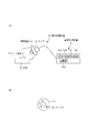
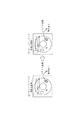
図1は、本発明の第1実施形態に係る物体認識装置の概略構成を示す説明図である。図1(a)に示す物体認識装置30は、プリント基板31が載置される定盤32と、プリント基板31を撮像する撮像手段としてのカメラ33と、プリント基板31に光を照射する照明装置34とを備えている。また、物体認識装置30は、カメラ33により撮像された被探索画像を取り込んで、テンプレート画像を被探索画像内で走査し、パターンマッチング処理を行う画像処理装置35を備えている。カメラ33は、不図示のレンズにより光像を形成し、不図示の撮像素子により光像を撮像信号に変換し、撮像信号を被探索画像として画像処理装置35に提供するコネクタ36を含む被探索画像を入手する撮像手段である。照明装置34は、カメラ33に付属したリング照明である。
[First Embodiment]
FIG. 1 is an explanatory diagram showing a schematic configuration of an object recognition apparatus according to the first embodiment of the present invention. An object recognition device 30 shown in FIG. 1A includes a surface plate 32 on which a
画像処理装置35は、物体認識装置全体を制御するCPU35Aと、CPU35Aを動作させるプログラムPが記憶されたROM35Bと、作業領域として一時的にデータが記憶されるRAM35Cと、を有するコンピュータである。また、画像処理装置35は、テンプレート画像、被探索画像等のデータが記憶される記憶手段として書き換え可能な不揮発性メモリ(例えばEEPROM)又はHDD等で構成された記憶部35Dを有している。プリント基板31には、図1(b)に示すように、コネクタ36が設けられており、本第1実施形態では、コネクタ36が検出物(物体認識対象)である。
The image processing device 35 is a computer having a
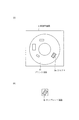
図2には、被探索画像Iとテンプレート画像ITが図示されている。図2(a)において、カメラ33で撮像されたプリント基板31を含む被探索画像Iは、記憶部35Dに記憶される。この記憶部35Dには、基準となるプリント基板を含む画像からコネクタ36の周辺部を切り出した画像をテンプレート画像ITとして予め記憶させている。このテンプレート画像ITの範囲は、ユーザが任意に設定することが可能である。
2 shows, the search image I and the template image I T is illustrated. In FIG. 2A, the searched image I including the printed
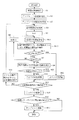
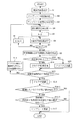
次に、図3に示すプログラムPに基づくCPU35Aの動作フローについて図4,図5及び図6を参照しながら説明する。まず、図3に示すように、CPU35Aは、カメラ33に撮像の指示を与えて撮像を開始させ、被探索画像Iを取得し、被探索画像Iを記憶部35Dに記憶させる(S1)。
Next, the operation flow of the
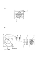
次いで、CPU35Aは、予め記憶部35Dに記憶させていたテンプレート画像ITを読み出し(S2)、図5(a)に示すように所定数N4(例えば12)のテンプレート画像片itに分割する(S3:テンプレート画像分割ステップ)。このCPU35AによるS3の処理が、テンプレート画像分割手段として機能する。
Then, CPU 35a reads out the template image I T which has been stored in advance in the
また、CPU35Aは、図5(b)に示すように、被探索画像Iからテンプレート画像ITと同一のサイズの部分画像ISを抜き出し、各テンプレート画像片itに対応して所定数N4(=12)の部分画像片isに分割する(S4:部分画像分割ステップ)。このCPU35AによるS4の処理が、部分画像分割手段として機能する。
Further, CPU 35a, as shown in FIG. 5 (b), extracting a partial image I S of the template image I T and the same size from the search image I, the predetermined number corresponding to each template image pieces i t N4 ( = 12) is divided into partial image section i s of (S4: partial image dividing step). The process of S4 by the
次に、CPU35Aは、分割したテンプレート画像片itと部分画像片isとを用いてパターンマッチングを行う。具体的には、CPU35Aは、抜き出した部分画像ISの各部分画像片isに番号1〜12を割り振ると共に、各テンプレート画像片itに番号1〜12を割り振り、各画像片it,is同士の対応関係(同じ数字の部分)を特定する。次いで、CPU35Aは、番号を示す変数kを1に設定し(S5)、変数kに対応する画像片it,is同士の相関値を計算により求める(S6)。この相関値の計算には、正規化相関法を用いる。相関値を求める計算式として下記の数1の式を用いる。
Then, CPU 35a performs pattern matching by using the divided template image piece i t and the partial image section i s. Specifically, CPU 35a is extracted partial image I with allocating numbers 1-12 in each partial image section i s of S, allocate numbers 1-12 in each template image pieces i t, each image piece i t, correspondence between the i s with each other to identify the (same part number). Then, CPU 35a sets the variable k indicating the number 1 (S5), the image pieces i t corresponding to the variable k, obtained by calculating the correlation values of i s between (S6). For the calculation of the correlation value, a normalized correlation method is used. The following

なお、画像片内の位置(i,j)とは、図6に示すように、被探索画像Iからテンプレート画像ITに対応する大きさの画像を抽出した部分画像ISの部分画像片is内の位置又はテンプレート画像ITのテンプレート画像片it内の位置である。つまり、位置(i,j)は、ピクセル単位で表される座標を示し、各画像片it,isのピクセル毎にfij,gijを求め、相関値Rを求める。相関値Rは1が最も類似性が高いことを表し、−1が最も低いことを表す。 The position of the image pieces (i, j) and, as shown in FIG. 6, the partial image piece i of the partial image I S obtained by extracting the image of a size corresponding to the template image I T from the search image I a position or positions in the template image piece i t of the template image I T in s. That is, the position (i, j) are the coordinates expressed in pixels, determine the f ij, g ij for each pixel in each image piece i t, i s, obtains a correlation value R. For the correlation value R, 1 represents the highest similarity, and -1 represents the lowest similarity.
次に、CPU35Aは、k=N4(12)となったか否かを判断し(S7)、kがN4よりも小さいと判断した場合は(S7:NO)、kをインクリメントし(S8)、次の番号に対応する画像片it,is同士の相関値を計算により求めるS6の処理に移行する。
Next, the
CPU35Aは、k=N4、つまり全ての画像片it,is同士の相関値を求めたと判断した場合(S7:YES)、類似性があるとする所定閾値以上(例えば0.95以上)となる相関値の個数を集計して集計値を求める(S9)。すなわち、S6〜S9が演算ステップに相当し、CPU35AのS6〜S9の処理動作が演算手段として機能するものである。この所定閾値は、画像片同士が合致していると認識される値に設定される。
CPU35A is, k = N4, i.e. all the image pieces i t, if it is determined that the correlation value of the i s between (S7: YES), or greater than a predetermined threshold value to a certain similarity (e.g. 0.95 or higher) The total number of correlation values is calculated to obtain a total value (S9). That is, S6 to S9 correspond to calculation steps, and the processing operations of S35 to S9 of the
次に、CPU35Aは、S9で求められた集計値が予め設定された第1所定値N1(例えば5)以上であるか否かを判断する(S10)。この第1所定値N1は、所定数N4よりも小さい値に設定される。CPU35Aは、S9で求められた集計値が第1所定値N1以上の場合(S10:YES)、その集計値に対応する部分画像ISの位置を合致候補位置として認識する(S11)。この第1所定値N1は、テンプレート画像ITと部分画像ISとが合致している可能性のあると判断される値に設定される。つまり、集計値が第1所定値以上(5個以上)であれば特定の検出物(コネクタ36)の候補として認識する。このとき、コネクタ36の合致候補位置として被探索画像I内での部分画像ISの位置と集計値、各テンプレート画像片itと部分画像片isとの相関値を記憶部35Dに記憶する。
Next, the
なお、CPU35Aは、S9で求められた集計値が第1所定値N1を下回る場合(S10:NO)、つまり、4個以下の場合、部分画像ISとテンプレート画像ITとは合致しない、つまり、特定のコネクタ36ではないと認識する(S12)。 Incidentally, CPU 35a, when the aggregate value determined in S9 below a first predetermined value N1 (S10: NO), that is, if four or less, does not match the partial image I S and the template image I T, i.e. It is recognized that it is not a specific connector 36 (S12).
次に、CPU35Aは、被探索画像I全体を走査したか否かを判断する(S13)。CPU35Aは、被探索画像Iの全体を走査していない場合(S13:NO)、ピクセル単位で範囲をずらし、次にパターンマッチングする部分画像ISを特定(記憶部35Dに記憶)し(S14)、ステップS4の処理に移行する。
Next, the
CPU35Aは、被探索画像Iの全体の走査が終了した場合(S13:YES)、コネクタ認識処理に移行する(S15:認識ステップ)。CPU35Aは、このS15において、S14の処理を繰り返すことでS9にて得られた1つ以上の集計値のうち、第1所定値N1以上となる集計値の中から最大値となる集計値を1つ抽出し、その集計値に対応する部分画像ISの位置を合致位置と認識する。つまり、CPU35Aは、テンプレート画像ITと合致する部分画像ISの合致位置を認識する。このCPU35AによるS15の処理動作が認識手段として機能する。次いで、CPU35Aは、認識結果として、認識したコネクタ36の位置を(x1,y1)の二次元座標で出力する。なお、座標(x1,y1)は、被探索画像Iにおける位置である。
When the entire scanning of the searched image I is completed (S13: YES), the
次に、CPU35Aは、S15にて合致位置が認識された際の集計値が、所定数N4よりも小さく且つ第1所定値N1よりも大きい値に設定された第2所定値N2(例えば7)以下であるか否かを判断する(S16)。CPU35Aは、S16において、第2所定値N2を上回ると判断した場合は(S16:NO)、パターンマッチングを終了する。この第2所定値N2は、認識された部分画像と、設定されているテンプレート画像とで輝度が物体認識の精度に影響を及ぼす可能性のある境界の値に設定されている。つまり、集計値が第2所定値以下の場合は、テンプレート画像を設定したときよりも照明装置34の輝度が低下している場合を示している。
Next, the
したがって、CPU35Aは、S16において、第2所定値N2(=7)以下の場合は、テンプレート更新を行う(S17:更新ステップ)。すなわち、CPU35Aは、テンプレート画像ITを、S15で認識された合致位置に対応する部分画像ISに置き換える。具体的には、CPU35Aは、コネクタ36として認識した位置の部分画像ISを新たなテンプレート画像ITとして記憶部35Dに記憶させる。
Therefore, the
以上のS1〜S17の動作で、1枚目のプリント基板31における物体認識動作が終了するが、認識終了したプリント基板31と次のプリント基板31とが入れ換えられ、次のプリント基板31の物体認識動作を行う場合は、S1に戻って処理を実行する。
The object recognition operation on the first printed
S15の動作により、部分画像ISにおいて部分的に輝度変動が起こり、一部の相関値が低下しても物体を認識することができ、短期的及び長期的な輝度変動に対して物体の認識精度を向上させることができる。また、例えば照明装置34の長期使用により照明装置34が劣化して輝度が徐々に低下し、撮像された被探索画像Iに部分的な輝度変化が生じても、S15で認識された部分画像ISの集計値が第2所定値N2以下の場合にテンプレート画像ITが置き換えられる。したがって、テンプレート画像ITを、被探索画像Iを撮像したときの現状の照明環境に近い状態に更新され、物体が認識不能な状態となるのを防ぐことができ、長期に亘って物体の認識精度を向上させることができる。更に、テンプレート画像ITをパターンマッチングの度に毎回更新するのではなく、S16において判断基準を設けているので、認識基準となるテンプレート画像ITに誤差が累積して大きな誤差が含まれてしまうのを未然に防ぐことができる。これにより、長期に亘り正確に認識することができる。 By the operation of S15, occurs partially brightness variation in the partial image I S, a part of it is that the correlation value to recognize an object be reduced, the recognition of the object with respect to short-term and long-term brightness variation Accuracy can be improved. Further, for example, even when the illumination device 34 deteriorates due to long-term use of the illumination device 34 and the luminance gradually decreases and a partial luminance change occurs in the captured image I to be searched, the partial image I recognized in S15. When the total value of S is equal to or smaller than the second predetermined value N2, the template image IT is replaced. Therefore, the template image IT can be updated to a state close to the current lighting environment when the image to be searched I is imaged, and the object can be prevented from becoming unrecognizable. Accuracy can be improved. Further, instead of updating every time the template image I T every time the pattern matching, since the provided criteria in S16, will contain a large error in error is accumulated in the template image I T as the recognition criteria Can be prevented in advance. Thereby, it can recognize correctly over a long period of time.
ここで、S15におけるコネクタ認識処理について詳細に説明する。図4に示すように、CPU35Aは、被探索画像Iの全体を走査した結果、S11にて認識された合致候補位置の個数が複数個であるか否かを判断する(S21)。つまり、第1所定値N1(=5)以上となった集計値の個数が複数個であるか否かを判断する。
Here, the connector recognition process in S15 will be described in detail. As shown in FIG. 4, as a result of scanning the entire searched image I, the
CPU35Aは、S21の判断処理で合致候補位置の個数が複数個あると判断した場合(S21:YES)、合致候補位置に対応する各集計値の中から最大値となる集計値に対応する部分画像ISの合致候補位置を抽出する(S22)。
When the
次いで、CPU35Aは、S22で抽出された合致候補位置の個数が複数個であるか否かを判断する(S23)。つまり、最大値となった集計値の個数が複数個であるか否か判断する。次に、CPU35Aは、これら合致候補位置に対応する集計値を集計する際に用いた相関値の合計値をそれぞれ演算する(S24)。次に、CPU35Aは、各合計値の中で、最大値となる合計値に対応する合致候補位置を合致位置と認識し(S25)、図3に示すS16の判断処理に移行する。
Next, the
また、CPU35Aは、S21において合致候補位置の個数が1個と判断した場合(S21:NO)、又はS23において合致候補位置の個数が1個と判断した場合(S23:NO)、その合致候補位置を合致位置と認識する(S26)。なお、CPU35Aは、S25,S26の処理において、合致位置と認識した際の集計値を記憶部35Dに記憶させておく。
Further, when the
このように、S3,S4にてテンプレート画像IT及び部分画像ISを所定数N4のテンプレート画像片it及び部分画像片isに分割し、S6にて各画像片it,is同士の相関値を求めている。そして、部分画像ISにおいて部分的に影が生じる短期的な輝度変動やシェーディングが生じる長期的な輝度変動が起こり、一部の相関値が低下しても、S10の判断で集計値が第1所定値N1以上であれば、S25,S26にて合致位置として認識される。したがって、一部分の輝度変動に対して物体の認識精度を向上させることができる。さらに、S21の判断処理で合致候補位置(第1所定値N1以上となる集計値)が複数あると判断された場合には、それら集計値の中で最大値の集計値に対応する合致候補位置を合致位置としている。したがって、複数の合致候補位置がある場合でも、合致位置を正確に決めることができる。 Thus, S3, S4 divides the template image I T and the partial image I S in the template image piece i t and the partial image sections i s of a predetermined number N4 in each image piece i t at S6, i s together The correlation value is obtained. Then, it occurs term brightness variations short-term brightness variations and shading partially shadow occurs in the partial image I S is generated, even if some of the correlation values is reduced, the aggregate value is determined in S10 first If it is greater than or equal to the predetermined value N1, it is recognized as a match position in S25 and S26. Therefore, the recognition accuracy of an object can be improved with respect to a part of luminance fluctuations. Furthermore, if it is determined in the determination process of S21 that there are a plurality of match candidate positions (total values that are equal to or greater than the first predetermined value N1), match candidate positions corresponding to the maximum total value among the total values Is the matching position. Therefore, even when there are a plurality of match candidate positions, the match positions can be accurately determined.
[第2実施形態]
次に、第2実施形態に係る物体認識装置について説明する。本第2実施形態の物体認識装置の構成は、図1に示す構成と同一である。図7に、本第2実施形態の物体認識装置の動作フローを示す。なお、上記第1実施形態で説明した処理と同一の処理を行うステップには、図3と同一符号を付している。
[Second Embodiment]
Next, an object recognition apparatus according to the second embodiment will be described. The configuration of the object recognition apparatus of the second embodiment is the same as the configuration shown in FIG. FIG. 7 shows an operation flow of the object recognition apparatus of the second embodiment. In addition, the same code | symbol as FIG. 3 is attached | subjected to the step which performs the process same as the process demonstrated in the said 1st Embodiment.
まずCPU35Aは、上記第1実施形態と同様に、S1〜S5の処理を順次実行する。次いで、CPU35Aは、番号kに対応する画像片it,is同士の相関値を計算により求める(S6−1)。この相関値の計算には、正規化相関法を用いる。相関値を求める計算式として上述した数1の式を用いる。
First, the
次に、CPU35Aは、S6−1で求めたk個の相関値のうち、所定閾値(=0.95)よりも小さい相関値の個数mを集計する(S6−2)。次に、CPU35Aは、所定閾値よりも小さい値となる相関値の個数mが、所定数N4から第1所定値N1を差し引いた差分値を超えたか否か、つまりm>N4−N1となったか否かを判断する(S6−3)。例えば、N4=12,N1=5の場合、相関値の個数mが7個を超えて8個となったか否か、つまり、m>7となったか否かを判断する。
Next, the
CPU35Aは、相関値を順次求める際に、相関値の個数mが差分値(N4−N1)を超えたと判断した場合(S6−3:YES)、残りのテンプレート画像片itと部分画像片isとの相関値の演算を打ち切る、つまり、S12の処理に移行する。すなわち、被検索画像Iにおいて、合致候補となる部分画像の数は、被探索画像を走査する部分画像の全数に比して極めて少ない。したがって、このS6−3では合致候補位置とはなり得ない部分画像については、途中で相関値の演算が打ち切られる。なお、CPU35Aは、相関値の個数mが差分値(N4−N1)を超えていないと判断した場合(S6−3:NO)、S7の処理に移行する。S7では、上述したように、k=N4となったか否かが判断され、k=N4でなければ、kをインクリメントし(S8)、S6−1の処理に移行する。また、k=N4であれば、S9の処理に移行する。
CPU35A, when obtaining a correlation value sequentially, when the number m of the correlation value has exceeded a difference value (N4-N1) (S6-3: YES), the remainder of the template image piece i t and the partial image section i The calculation of the correlation value with s is terminated, that is, the process proceeds to S12. That is, in the image to be searched I, the number of partial images that are match candidates is extremely small compared to the total number of partial images that scan the image to be searched. Therefore, for the partial image that cannot be a match candidate position in S6-3, the calculation of the correlation value is terminated halfway. If the
以上、本第2実施形態によれば、上記第1実施形態と同様の効果を奏すると共に、残りのテンプレート画像片itと部分画像片isとの相関値の演算が打ち切られるので、上記第1実施形態よりも演算量が減少し、物体認識の処理が高速化するという効果を奏する。 As described above, according to the second embodiment, the effects similar to those of the first embodiment, since the calculation of the correlation values with the rest of the template image piece i t and the partial image section i s aborted, the first Compared to the first embodiment, the amount of calculation is reduced, and the object recognition process is speeded up.
[第3実施形態]
次に、第3実施形態に係る物体認識装置について説明する。本第3実施形態の物体認識装置の構成は、図1に示す構成と同一である。図8に、本第3実施形態の物体認識装置の動作フローを示す。なお、上記第1実施形態で説明した処理と同一の処理を行うステップには、図3と同一符号を付している。本第3実施形態においては、テンプレート画像を更新するか否かの判断が、上記第1実施形態と異なる。
[Third Embodiment]
Next, an object recognition apparatus according to the third embodiment will be described. The configuration of the object recognition apparatus of the third embodiment is the same as the configuration shown in FIG. FIG. 8 shows an operation flow of the object recognition apparatus of the third embodiment. In addition, the same code | symbol as FIG. 3 is attached | subjected to the step which performs the process same as the process demonstrated in the said 1st Embodiment. In the third embodiment, the determination whether or not to update the template image is different from that in the first embodiment.
被探索画像は、図1に示すプリント基板31が入れ換えられる度、カメラ33にて撮像される。まず、1枚目の被探索画像I1の走査が終了するまでは、図3に示すフローを実行する。このとき、図9に示すように、被探索画像I1内の合致位置として認識された部分画像ISの集計値1が記憶部35D(図1)に記憶される。
The searched image is picked up by the camera 33 every time the printed
次にプリント基板31が入れ換えられて2枚目以降の被探索画像I2がカメラ33により撮像された場合、CPU35Aは、図8に示す各処理を実行する。具体的に説明すると、CPU35Aは、S1〜S15の処理を実行した後、今回の走査でS25又はS26(図4)にて合致位置が認識された際の集計値2が第2所定値N2(=7)以下であるか否かを判断する(S16−1)。ここで、記憶部35Dには、過去(前回)の被探索画像I1の走査でS25又はS26にて合致位置が認識されたされた際の集計値1が記憶されている。
Next, when the printed
従って、CPU35Aは、集計値2が第2所定値N2以下の場合(S16−1:YES)、前回の走査で合致位置が認識された際の記憶部35Dに記憶されている集計値1と今回の走査でS25,S26にて合致位置が認識された際の集計値2との差分値を求める。そして、CPU35Aは、この求めた差分値が予め設定された第3所定値N3以下であるか否かを判断する(S16−2)。この第3所定値N3は、(N4−N1)以下の値(例えば3)である。
Therefore, when the
つまり、この第3所定値N3は、前回の被探索画像I1の走査で認識した部分画像と、今回の被探索画像I2の走査で認識した部分画像とで輝度変化が著しく異なることとなる境界の値に設定される。すなわち、このS16−2では、照明装置34の短期的な輝度変動の大きさを判断していることとなる。照明装置34の輝度変動が小さい場合は、求めた差分値が第3所定値以下となり、照明装置34の輝度変動が大きい場合は、差分値が第3所定値を超えることとなる。 That is, the third predetermined value N3 becomes the partial images recognized by the previous scan of the search image I 1, and significantly different luminance change in the current partial image recognized by the scanning of the search image I 2 Set to the boundary value. That is, in S16-2, the magnitude of short-term luminance fluctuation of the lighting device 34 is determined. When the luminance variation of the lighting device 34 is small, the obtained difference value is equal to or smaller than the third predetermined value, and when the luminance variation of the lighting device 34 is large, the difference value exceeds the third predetermined value.
CPU35Aは、差分値が第3所定値N3以下の場合(S16−2:YES)、テンプレート画像ITを、今回の走査でS25,S26にて合致位置と認識された部分画像に置き換える、テンプレート更新の処理を実行する(S17)。なお、集計値2が第2所定値N2を超える場合(S16−1:NO)、又は差分値が第3所定値N3を超える場合(S16−2:NO)、CPU35Aは、テンプレート更新は行わず、パターンマッチングを終了する。
CPU35A, if the difference value is less than the third predetermined value N3 (S16-2: YES), the template image I T, replaced by current scan in S25, the recognized partial image and the matching position at S26, the template update The process is executed (S17). When the
本第3実施形態では、前パターンマッチングで認識したコネクタ領域(部分画像)と現パターンマッチングで認識したコネクタ領域(部分画像)との輝度変動の大きさを判断することができる。これにより、S16−2でNOであれば、短期的な輝度変動であり、S16−2でYESであれば、短期的な輝度変化ではなく長期的な輝度変化であると区別することができる。そのため、装置や人間の動作により短期的に影ができた場合に、テンプレート画像が更新されるのを防ぐことができ、テンプレート画像の誤差の拡大を防ぐことができる。したがって、長期に亘って物体の認識精度を向上させることができる。 In the third embodiment, it is possible to determine the magnitude of the luminance variation between the connector region (partial image) recognized by the previous pattern matching and the connector region (partial image) recognized by the current pattern matching. Thus, if NO in S16-2, it is a short-term luminance change, and if YES in S16-2, it can be distinguished that it is a long-term luminance change, not a short-term luminance change. Therefore, it is possible to prevent the template image from being updated when a shadow is produced in the short term due to the operation of the apparatus or human beings, and it is possible to prevent an increase in the error of the template image. Therefore, the recognition accuracy of the object can be improved over a long period of time.
なお、上記実施形態に基づいて本発明を説明したが、本発明はこれに限定されるものではない。上記第3実施形態の処理を、上記第2実施形態の処理に適用することも可能である。また、本発明の機能処理をコンピュータで実現するために、コンピュータにインストールされるプログラムコード自体も本発明を実現するものであり、本発明は、コンピュータプログラム自体も含まれる。プログラムの供給方法としては、クライアントコンピュータのブラウザを用いてインターネットのホームページに接続し、ホームページから本発明のプログラムをハードディスク等の記録媒体にダウンロードすることによっても供給できる。また、本発明のプログラムを構成するプログラムコードを複数のファイルに分割し、それぞれのファイルを異なるホームページからダウンロードすることによっても実現可能である。つまり、本発明の機能処理をコンピュータで実現するためのプログラムファイルを複数のユーザに対してダウンロードさせるWWWサーバも、本発明に含まれるものである。また、コンピュータが、プログラムの指示に基づき、コンピュータ上で稼動しているOSなどが実際の処理の一部または全部を行ない、その処理によって上述実施形態の機能が実現される場合も含まれる。 In addition, although this invention was demonstrated based on the said embodiment, this invention is not limited to this. The processing of the third embodiment can be applied to the processing of the second embodiment. Further, since the functions of the present invention are implemented by computer, the program code installed in the computer also implements the present invention, and the present invention includes the computer program itself. The program can be supplied by connecting to a homepage on the Internet using a browser of a client computer and downloading the program of the present invention from the homepage to a recording medium such as a hard disk. It can also be realized by dividing the program code constituting the program of the present invention into a plurality of files and downloading each file from a different homepage. That is, a WWW server that allows a plurality of users to download a program file for realizing the functional processing of the present invention on a computer is also included in the present invention. In addition, the case where the computer performs the function of the above-described embodiment by performing part or all of the actual processing based on the instruction of the program and by the OS running on the computer being included.
30 物体認識装置
31 プリント基板
32 定盤
33 カメラ
34 照明装置
35 画像処理装置
35A CPU(テンプレート画像分割手段,部分画像分割手段,演算手段,認識手段,更新手段)
I 被探索画像
IS 部分画像
is 部分画像片
IT テンプレート画像
it テンプレート画像片
30
I the search image I S partial image i s partial image fragment I T template image i t template image piece
Claims (9)
前記テンプレート画像を所定数のテンプレート画像片に分割するテンプレート画像分割手段と、
前記被探索画像から前記テンプレート画像と同一のサイズの部分画像を抜き出し、前記各テンプレート画像片に対応して所定数の部分画像片に分割する部分画像分割手段と、
前記テンプレート画像片と前記部分画像片とのそれぞれの相関値を求め、所定閾値以上となる前記相関値の個数を集計して集計値を求める演算手段と、
前記被探索画像の全体を走査した結果、前記演算手段により得られた集計値のうち、予め設定された第1所定値以上となる集計値の中から最大値となる集計値を1つ抽出し、その集計値に対応する部分画像の位置を合致位置と認識する認識手段と、
前記認識手段により前記合致位置が認識された際の集計値が、前記所定数よりも小さい値で且つ前記第1所定値よりも大きい値に設定された第2所定値以下の場合は、前記テンプレート画像を、前記認識手段で認識された前記合致位置に対応する部分画像に置き換える更新手段と、を備えたことを特徴とする物体認識装置。 In an object recognition device that scans a template image in a searched image and performs pattern matching,
Template image dividing means for dividing the template image into a predetermined number of template image pieces;
A partial image dividing means for extracting a partial image having the same size as the template image from the searched image and dividing it into a predetermined number of partial image pieces corresponding to the template image pieces;
Calculating means for obtaining a correlation value between each of the template image piece and the partial image piece, and calculating a total value by counting the number of the correlation values equal to or greater than a predetermined threshold;
As a result of scanning the entire image to be searched, one total value that is the maximum value is extracted from the total values that are equal to or greater than the first predetermined value that is set in advance, among the total values obtained by the calculation means. Recognizing means for recognizing the position of the partial image corresponding to the total value as a matching position;
When the total value when the matching position is recognized by the recognition means is equal to or smaller than the second predetermined value set to a value smaller than the predetermined number and larger than the first predetermined value, the template An object recognizing apparatus comprising: an updating unit that replaces an image with a partial image corresponding to the matching position recognized by the recognizing unit.
前記テンプレート画像を所定数のテンプレート画像片に分割するテンプレート画像分割手段と、
前記被探索画像から前記テンプレート画像と同一のサイズの部分画像を抜き出し、前記各テンプレート画像片に対応して所定数の部分画像片に分割する部分画像分割手段と、
前記テンプレート画像片と前記部分画像片とのそれぞれの相関値を求め、所定閾値以上となる前記相関値の個数を集計して集計値を求める演算手段と、
前記被探索画像の全体を走査した結果、前記演算手段により得られた集計値のうち、予め設定された第1所定値以上となる集計値の中から最大値となる集計値を1つ抽出し、その集計値に対応する部分画像の位置を合致位置と認識する認識手段と、
今回の走査で前記認識手段により前記合致位置が認識された際の集計値が、前記所定数よりも小さい値で且つ前記第1所定値よりも大きい値に設定された第2所定値以下であって、過去の走査で前記認識手段により前記合致位置が認識された際の集計値と今回の走査で前記認識手段により前記合致位置が認識された際の集計値との差分値が、予め設定された第3所定値以下の場合は、前記テンプレート画像を、今回の走査で前記認識手段により認識された前記合致位置に対応する部分画像に置き換える更新手段と、を備えたことを特徴とする物体認識装置。 In an object recognition device that scans a template image in a searched image and performs pattern matching,
Template image dividing means for dividing the template image into a predetermined number of template image pieces;
A partial image dividing means for extracting a partial image having the same size as the template image from the searched image and dividing it into a predetermined number of partial image pieces corresponding to the template image pieces;
Calculating means for obtaining a correlation value between each of the template image piece and the partial image piece, and calculating a total value by counting the number of the correlation values equal to or greater than a predetermined threshold;
As a result of scanning the entire image to be searched, one total value that is the maximum value is extracted from the total values that are equal to or greater than the first predetermined value that is set in advance, among the total values obtained by the calculation means. Recognizing means for recognizing the position of the partial image corresponding to the total value as a matching position;
The total value when the matching position is recognized by the recognition means in the current scan is less than or equal to a second predetermined value set to a value smaller than the predetermined number and larger than the first predetermined value. Thus, a difference value between the total value when the matching position is recognized by the recognition unit in the previous scan and the total value when the matching position is recognized by the recognition unit in the current scan is set in advance. And an update unit that replaces the template image with a partial image corresponding to the matching position recognized by the recognition unit in a current scan when the value is equal to or less than a third predetermined value. apparatus.
前記テンプレート画像を所定数のテンプレート画像片に分割するテンプレート画像分割ステップと、
前記被探索画像から前記テンプレート画像と同一のサイズの部分画像を抜き出し、前記各テンプレート画像片に対応して所定数の部分画像片に分割する部分画像分割ステップと、
前記テンプレート画像片と前記部分画像片とのそれぞれの相関値を求め、所定閾値以上となる前記相関値の個数を集計して集計値を求める演算ステップと、
前記被探索画像の全体を走査した結果、前記演算ステップにて得られた集計値のうち、予め設定された第1所定値以上となる集計値の中から最大値となる集計値を1つ抽出し、その集計値に対応する部分画像の位置を合致位置と認識する認識ステップと、
前記認識ステップにて前記合致位置が認識された際の集計値が、前記所定数よりも小さい値で且つ前記第1所定値よりも大きい値に設定された第2所定値以下の場合は、前記テンプレート画像を、前記認識ステップで認識された前記合致位置に対応する部分画像に置き換える更新ステップと、を備えたことを特徴とする物体認識方法。 In an object recognition method that scans a template image in a searched image and performs pattern matching,
A template image dividing step for dividing the template image into a predetermined number of template image pieces;
A partial image dividing step of extracting a partial image of the same size as the template image from the searched image and dividing it into a predetermined number of partial image pieces corresponding to the template image pieces;
Calculating a correlation value between each of the template image piece and the partial image piece, calculating a total value by counting the number of the correlation values that are equal to or greater than a predetermined threshold; and
As a result of scanning the entire searched image, one total value that is the maximum value is extracted from the total values that are equal to or greater than the first predetermined value that is set in advance, among the total values obtained in the calculation step. A recognition step for recognizing the position of the partial image corresponding to the total value as a matching position;
When the total value when the matching position is recognized in the recognition step is equal to or less than a second predetermined value set to a value smaller than the predetermined number and larger than the first predetermined value, An object recognition method comprising: an updating step of replacing a template image with a partial image corresponding to the matching position recognized in the recognition step.
前記テンプレート画像を所定数のテンプレート画像片に分割するテンプレート画像分割ステップと、
前記被探索画像から前記テンプレート画像と同一のサイズの部分画像を抜き出し、前記各テンプレート画像片に対応して所定数の部分画像片に分割する部分画像分割ステップと、
前記テンプレート画像片と前記部分画像片とのそれぞれの相関値を求め、所定閾値以上となる前記相関値の個数を集計して集計値を求める演算ステップと、
前記被探索画像の全体を走査した結果、前記演算ステップにて得られた集計値のうち、予め設定された第1所定値以上となる集計値の中から最大値となる集計値を1つ抽出し、その集計値に対応する部分画像の位置を合致位置と認識する認識ステップと、
今回の走査で前記認識ステップにて前記合致位置が認識された際の集計値が、前記所定数よりも小さい値で且つ前記第1所定値よりも大きい値に設定された第2所定値以下であって、過去の走査で前記認識ステップにて前記合致位置が認識された際の集計値と今回の走査で前記認識ステップにて前記合致位置が認識された際の集計値との差分値が、予め設定された第3所定値以下の場合は、前記テンプレート画像を、今回の走査で前記認識ステップにて認識された前記合致位置に対応する部分画像に置き換える更新ステップと、を備えたことを特徴とする物体認識方法。 In an object recognition method that scans a template image in a searched image and performs pattern matching,
A template image dividing step for dividing the template image into a predetermined number of template image pieces;
A partial image dividing step of extracting a partial image of the same size as the template image from the searched image and dividing it into a predetermined number of partial image pieces corresponding to the template image pieces;
Calculating a correlation value between each of the template image piece and the partial image piece, calculating a total value by counting the number of the correlation values that are equal to or greater than a predetermined threshold; and
As a result of scanning the entire searched image, one total value that is the maximum value is extracted from the total values that are equal to or greater than the first predetermined value that is set in advance, among the total values obtained in the calculation step. A recognition step for recognizing the position of the partial image corresponding to the total value as a matching position;
The total value when the matching position is recognized in the recognition step in the current scan is less than or equal to a second predetermined value set to a value smaller than the predetermined number and larger than the first predetermined value. The difference value between the total value when the matching position is recognized in the recognition step in the previous scan and the total value when the matching position is recognized in the recognition step in the current scan is, An update step that replaces the template image with a partial image corresponding to the matching position recognized in the recognition step in the current scan when the third predetermined value or less is set in advance. An object recognition method.
Priority Applications (1)
| Application Number | Priority Date | Filing Date | Title |
|---|---|---|---|
| JP2009281747A JP5388828B2 (en) | 2009-12-11 | 2009-12-11 | Object recognition device, object recognition method and program |
Applications Claiming Priority (1)
| Application Number | Priority Date | Filing Date | Title |
|---|---|---|---|
| JP2009281747A JP5388828B2 (en) | 2009-12-11 | 2009-12-11 | Object recognition device, object recognition method and program |
Publications (3)
| Publication Number | Publication Date |
|---|---|
| JP2011123737A true JP2011123737A (en) | 2011-06-23 |
| JP2011123737A5 JP2011123737A5 (en) | 2013-01-31 |
| JP5388828B2 JP5388828B2 (en) | 2014-01-15 |
Family
ID=44287558
Family Applications (1)
| Application Number | Title | Priority Date | Filing Date |
|---|---|---|---|
| JP2009281747A Expired - Fee Related JP5388828B2 (en) | 2009-12-11 | 2009-12-11 | Object recognition device, object recognition method and program |
Country Status (1)
| Country | Link |
|---|---|
| JP (1) | JP5388828B2 (en) |
Cited By (2)
| Publication number | Priority date | Publication date | Assignee | Title |
|---|---|---|---|---|
| JP2014527655A (en) * | 2011-07-14 | 2014-10-16 | バイエリッシェ モートーレン ウエルケ アクチエンゲゼルシャフトBayerische Motoren Werke Aktiengesellschaft | Pedestrian gait recognition method and device for portable terminal |
| CN114267050A (en) * | 2021-12-14 | 2022-04-01 | 咪咕音乐有限公司 | Human body action recognition method and device, terminal device and storage medium |
Citations (5)
| Publication number | Priority date | Publication date | Assignee | Title |
|---|---|---|---|---|
| JPH0962838A (en) * | 1995-08-24 | 1997-03-07 | Nachi Fujikoshi Corp | High-speed pattern matching method |
| JP2001236500A (en) * | 2000-02-21 | 2001-08-31 | Hitachi Ltd | Image determination method and defect inspection device |
| JP2005300322A (en) * | 2004-04-09 | 2005-10-27 | Nikon Corp | Position detection device |
| JP2007309729A (en) * | 2006-05-17 | 2007-11-29 | Matsushita Electric Ind Co Ltd | Appearance inspection method for press-worked products and appearance inspection device used therefor |
| JP2008269258A (en) * | 2007-04-19 | 2008-11-06 | Matsushita Electric Works Ltd | Template matching device |
-
2009
- 2009-12-11 JP JP2009281747A patent/JP5388828B2/en not_active Expired - Fee Related
Patent Citations (5)
| Publication number | Priority date | Publication date | Assignee | Title |
|---|---|---|---|---|
| JPH0962838A (en) * | 1995-08-24 | 1997-03-07 | Nachi Fujikoshi Corp | High-speed pattern matching method |
| JP2001236500A (en) * | 2000-02-21 | 2001-08-31 | Hitachi Ltd | Image determination method and defect inspection device |
| JP2005300322A (en) * | 2004-04-09 | 2005-10-27 | Nikon Corp | Position detection device |
| JP2007309729A (en) * | 2006-05-17 | 2007-11-29 | Matsushita Electric Ind Co Ltd | Appearance inspection method for press-worked products and appearance inspection device used therefor |
| JP2008269258A (en) * | 2007-04-19 | 2008-11-06 | Matsushita Electric Works Ltd | Template matching device |
Cited By (2)
| Publication number | Priority date | Publication date | Assignee | Title |
|---|---|---|---|---|
| JP2014527655A (en) * | 2011-07-14 | 2014-10-16 | バイエリッシェ モートーレン ウエルケ アクチエンゲゼルシャフトBayerische Motoren Werke Aktiengesellschaft | Pedestrian gait recognition method and device for portable terminal |
| CN114267050A (en) * | 2021-12-14 | 2022-04-01 | 咪咕音乐有限公司 | Human body action recognition method and device, terminal device and storage medium |
Also Published As
| Publication number | Publication date |
|---|---|
| JP5388828B2 (en) | 2014-01-15 |
Similar Documents
| Publication | Publication Date | Title |
|---|---|---|
| JP7102103B2 (en) | Portable information processing equipment and methods and programs using the information processing equipment | |
| JP5825172B2 (en) | Image determination apparatus, image determination method, and computer program for image determination | |
| KR102084535B1 (en) | Defect inspection device, defect inspection method | |
| JP6405124B2 (en) | Inspection device, inspection method, and program | |
| JP6179224B2 (en) | Image processing filter creation apparatus and method | |
| CN103226823B (en) | Based on the Rapid Image Registration method of logarithm difference point set template | |
| JP6585793B2 (en) | Inspection device, inspection method, and program | |
| JP5388828B2 (en) | Object recognition device, object recognition method and program | |
| US6885777B2 (en) | Apparatus and method of determining image processing parameter, and recording medium recording a program for the same | |
| JP2006209698A (en) | Target tracking device, microscope system and target tracking program | |
| JP6478639B2 (en) | IMAGE PROCESSING APPARATUS, IMAGE PROCESSING METHOD, AND PROGRAM | |
| US20100091125A1 (en) | Template matching device, camera with template matching device, and program for allowing computer to carry out template matching | |
| JP2018197692A (en) | Damage state processing system | |
| JP2003022442A (en) | Object detection / position measurement method and device, and execution program of the method and recording medium thereof | |
| JP6025400B2 (en) | Work position detection device and work position detection method | |
| JP6700705B2 (en) | Distribution system, information processing method, and program | |
| EP3062516B1 (en) | Parallax image generation system, picking system, parallax image generation method, and computer-readable recording medium | |
| JP7034781B2 (en) | Image processing equipment, image processing methods, and programs | |
| JP6950376B2 (en) | Image processing device, training image processing device, image identification device, training image processing method, image identification method, and program | |
| JP6478897B2 (en) | Modulation transfer function calculation device and modulation transfer function calculation program | |
| US20180130230A1 (en) | Recognition apparatus, determination method, and article manufacturing method | |
| JP2001119622A (en) | Imaging device and control method thereof | |
| US9591220B2 (en) | Selection apparatus, selection method, and storage medium | |
| KR102690867B1 (en) | Pattern matching devices, pattern measurement systems, and non-transitory computer-readable media. | |
| KR101025568B1 (en) | Apparatus and method for focus position determination using entropy of image |
Legal Events
| Date | Code | Title | Description |
|---|---|---|---|
| RD03 | Notification of appointment of power of attorney |
Free format text: JAPANESE INTERMEDIATE CODE: A7423 Effective date: 20120203 |
|
| A521 | Written amendment |
Free format text: JAPANESE INTERMEDIATE CODE: A523 Effective date: 20121211 |
|
| A621 | Written request for application examination |
Free format text: JAPANESE INTERMEDIATE CODE: A621 Effective date: 20121211 |
|
| RD04 | Notification of resignation of power of attorney |
Free format text: JAPANESE INTERMEDIATE CODE: A7424 Effective date: 20130228 |
|
| A977 | Report on retrieval |
Free format text: JAPANESE INTERMEDIATE CODE: A971007 Effective date: 20130903 |
|
| TRDD | Decision of grant or rejection written | ||
| A01 | Written decision to grant a patent or to grant a registration (utility model) |
Free format text: JAPANESE INTERMEDIATE CODE: A01 Effective date: 20130910 |
|
| A61 | First payment of annual fees (during grant procedure) |
Free format text: JAPANESE INTERMEDIATE CODE: A61 Effective date: 20131008 |
|
| R151 | Written notification of patent or utility model registration |
Ref document number: 5388828 Country of ref document: JP Free format text: JAPANESE INTERMEDIATE CODE: R151 |
|
| LAPS | Cancellation because of no payment of annual fees |