JP2011129727A - Control method for gas laser oscillator, the gas laser oscillator and laser processing device - Google Patents
Control method for gas laser oscillator, the gas laser oscillator and laser processing device Download PDFInfo
- Publication number
- JP2011129727A JP2011129727A JP2009287124A JP2009287124A JP2011129727A JP 2011129727 A JP2011129727 A JP 2011129727A JP 2009287124 A JP2009287124 A JP 2009287124A JP 2009287124 A JP2009287124 A JP 2009287124A JP 2011129727 A JP2011129727 A JP 2011129727A
- Authority
- JP
- Japan
- Prior art keywords
- discharge current
- discharge
- laser
- target value
- voltage
- Prior art date
- Legal status (The legal status is an assumption and is not a legal conclusion. Google has not performed a legal analysis and makes no representation as to the accuracy of the status listed.)
- Pending
Links
Images


Landscapes
- Laser Beam Processing (AREA)
- Lasers (AREA)
Abstract
【課題】放電励起するための電極の表面に経年的に酸化膜が生成されても安定した放電励起ができる信頼性の高いガスレーザ発振装置およびレーザ加工装置の継続使用を可能とする。
【解決手段】レーザ出力の開始時に、放電電流目標値設定器は、無放電状態から放電するまでに要する放電開始電圧Vaへ上昇するに至るまでの予め設定された立ち上がり時間taの間、放電電流の目標値を設定して高電圧電源より電圧を出力し、その後、放電を維持するための放電維持電圧Vbまで低下するに至るまでの予め設定された立下り時間tbの間、放電電流の目標値をゼロと設定して高電圧電源の電圧の出力を停止し、その後、放電電流目標値設定器は放電電流の目標値を設定して高電圧電源からの電圧出力を再開して、放電電流を所望のレーザ出力に対応した値になるように放電電流をフィードバック制御する。
【選択図】図1A highly reliable gas laser oscillation apparatus and laser processing apparatus capable of stable discharge excitation even when an oxide film is formed on the surface of an electrode for discharge excitation over time can be continuously used.
At the start of laser output, a discharge current target value setter discharges a discharge current for a preset rise time ta until it reaches a discharge start voltage Va required from the no-discharge state to discharge. The target value of the discharge current is output during a preset fall time tb until the voltage is output from the high-voltage power supply and then lowered to the discharge sustain voltage Vb for maintaining the discharge. Set the value to zero to stop the output of the voltage of the high voltage power supply, then the discharge current target value setter sets the target value of the discharge current and restarts the voltage output from the high voltage power supply, The discharge current is feedback controlled so as to have a value corresponding to the desired laser output.
[Selection] Figure 1
Description
本発明はレーザ媒質にガスを用いたレーザ発振装置の制御方法およびレーザ発振装置およびレーザ加工装置に関するものである。 The present invention relates to a method for controlling a laser oscillation apparatus using a gas as a laser medium, a laser oscillation apparatus, and a laser processing apparatus.
近年、レーザ発振装置およびレーザ加工装置は加工対象物を非接触でかつ熱影響が少なく加工できるという特徴から多様な材質や形状の切断や溶接等に多用されている。 2. Description of the Related Art In recent years, laser oscillators and laser processing apparatuses are widely used for cutting and welding of various materials and shapes because of the feature that an object to be processed can be processed in a non-contact manner with little thermal influence.
従来、図2に示すような放電電流フィードバック機能を有するレーザ発振装置が用いられていた。以下、図2を参照しながら説明する。 Conventionally, a laser oscillation device having a discharge current feedback function as shown in FIG. 2 has been used. Hereinafter, a description will be given with reference to FIG.
レーザ媒質ガスを内部に有する放電管1はガラスなどの誘電体からなり、レーザ触媒ガスを放電励起するために銅などの金属を使用した電極3を介して高電圧電源4より適宜可変した電圧を印加する。
A
放電管1内のレーザ媒質ガスへの電圧印加によって発生した放電電流はホール効果を利用した電流−電圧変換器などを用いた放電電流検出器5により検出される。
A discharge current generated by applying a voltage to the laser medium gas in the
所望のレーザ出力に対応した放電電流となるように放電電流目標値を一般的には可変の定電圧回路によりなる放電電流目標値設定器6で設定し、放電電流検出器5からの信号と、放電電流目標値設定器6からの信号の差分を演算し制御系の応答性に応じて増幅するオペアンプなどからなる差動増幅器7で偏差信号として取り出す。
A discharge current target value is generally set by a discharge current target value setter 6 composed of a variable constant voltage circuit so that a discharge current corresponding to a desired laser output is obtained, and a signal from the
差動増幅器7からの偏差信号と、放電電流目標値設定器6からの放電電流目標値を加算するオペアンプなどからなる加算器8よりの信号を、高電圧電源4に与え、放電電流を所望のレーザ出力に対応した値になるように、レーザ媒質に印加する電圧を可変し放電電流をフィードバック制御する機能を有している。
A signal from an
この放電電流のフィードバック制御における放電電流目標値設定器6からの信号と、高電圧電源4の出力電圧と、放電電流の関係について図3(a)を参照しながら説明する。
The relationship between the signal from the discharge current target value setter 6 in the feedback control of the discharge current, the output voltage of the high
放電電流目標値設定器6から所望のレーザ出力に対応した放電電流目標値が信号として出力される。最初は放電していないため放電電流は流れておらず、放電電流検出器5からの信号はゼロであり、差動増幅器7からの信号は大となり加算器8へ入力される。
A discharge current target value corresponding to a desired laser output is output from the discharge current target value setter 6 as a signal. Since no discharge is performed at first, no discharge current flows, the signal from the
その結果、高電圧電源4の出力電圧は上昇を加速する。その後高電圧電源4の出力電圧が放電管1内で放電を開始するに必要な電圧であるところの放電開始電圧Vaに至ると電極3間で放電が発生し放電電流が流れ始め、放電管1内のインピーダンスは負性であるため高電圧電源4の出力電圧は放電を維持するに必要な電圧であるところの維持電圧Vbまで低下する。放電電流は放電電流検出器5によって信号変換され差動増幅器7と加算器8を経て放電電流目標設定器6の信号に重畳され放電電流はフィードバック制御により放電電流の目標値へ整定され、所望のレーザ出力を得る(例えば、特許文献1参照)。
As a result, the output voltage of the high
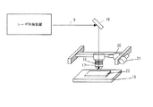
図4は従来のレーザ加工装置の概略構成の一例を示している。以下、図4を参照しながら従来のレーザ加工装置を説明する。 FIG. 4 shows an example of a schematic configuration of a conventional laser processing apparatus. Hereinafter, a conventional laser processing apparatus will be described with reference to FIG.
この図4において、レーザービーム9は、反射鏡15にて反射され、ワーク16近傍へ導かれる。レーザービーム9は、トーチ17内部に備えられた集光レンズ18によって高密度のエネルギビームに集光され、ワーク16に照射され、加工が行われる。ワーク16は加工テーブル19上に固定されており、X軸モータ20あるいはY軸モータ21によって、トーチ17はワーク16に対して相対的に移動する事で、所定の形状の加工が行われる。
In FIG. 4, the
このようなレーザ加工装置では、加工品質を向上させるため所望のレーザ出力を安定して取り出せる放電電流のフィードバック制御機能を有したレーザ発振装置が一般的である。 In such a laser processing apparatus, a laser oscillation apparatus having a discharge current feedback control function that can stably extract a desired laser output in order to improve processing quality is generally used.
しかしながら、従来のレーザ加工装置の構成であると、放電励起するための銅などの金属からなる電極の表面には経年的に酸化膜が生成される。酸化膜の生成は放電による温度の上昇と雰囲気の酸素およびオゾン濃度の上昇によって促進される。放電により酸化膜は都度局部的に絶縁破壊されているが、放電していない期間が継続すると電極表面全体を酸化膜が覆い電気絶縁材として放電を妨げる。 However, with the configuration of a conventional laser processing apparatus, an oxide film is formed over time on the surface of an electrode made of a metal such as copper for discharge excitation. The formation of the oxide film is promoted by the temperature rise due to the discharge and the oxygen and ozone concentrations in the atmosphere. Although the oxide film is locally broken down each time by the discharge, if the non-discharge period continues, the oxide film covers the entire electrode surface to prevent discharge as an electrical insulating material.
この様な場合において、上記従来のガスレーザ発振装置の制御方法やガスレーザ装置、およびレーザ加工装置の、放電電流目標値設定器からの信号と、高電圧電源の出力電圧と、放電電流の関係について図3(b)を参照しながら説明する。 In such a case, the relationship between the signal from the discharge current target value setter, the output voltage of the high-voltage power supply, and the discharge current in the control method of the conventional gas laser oscillation apparatus, the gas laser apparatus, and the laser processing apparatus is illustrated. This will be described with reference to 3 (b).
放電電流目標値設定器から所望のレーザ出力に対応した放電電流目標値が信号として出力される。最初は放電していないため放電電流は流れておらず、放電電流検出器からの信号はゼロであり、差動増幅器からの信号は大となり加算器へ入力される。その結果、高電圧電源の出力電圧は上昇を加速する。その後高電圧電源の出力電圧が放電管内で放電を開始するに必要な電圧であるところの放電開始電圧Vaに至っても電極表面の酸化膜の電気絶縁により放電せず、高電圧電源の出力電圧は更に上昇する。 A discharge current target value corresponding to a desired laser output is output as a signal from the discharge current target value setter. Since the discharge current does not flow at the beginning, the discharge current does not flow, the signal from the discharge current detector is zero, the signal from the differential amplifier becomes large and is input to the adder. As a result, the output voltage of the high voltage power supply accelerates the rise. After that, even when the output voltage of the high voltage power source reaches the discharge start voltage Va which is a voltage necessary for starting the discharge in the discharge tube, no discharge occurs due to the electrical insulation of the oxide film on the electrode surface, and the output voltage of the high voltage power source is It rises further.
この様な場合には、一般的には高電圧電源の過電圧保護機能などにより出力電圧がある値以上になった場合にアラーム停止とするため、ガスレーザ発振装置およびレーザ加工装置の継続使用を阻害するという課題を有していた。 In such a case, since the alarm is stopped when the output voltage exceeds a certain value due to an overvoltage protection function of a high voltage power supply, etc., the continuous use of the gas laser oscillation device and the laser processing device is hindered. It had the problem that.
本発明は、安定して継続使用ができる信頼性の高いガスレーザ発振装置およびレーザ加工装置を提供することを目的とする。 An object of the present invention is to provide a highly reliable gas laser oscillation apparatus and laser processing apparatus that can be stably used continuously.
本発明は、上記問題点を解決するために、レーザ媒質ガスを内部に有する放電管と、前記レーザ媒質ガスを放電励起するために電極を介して電圧を可変し印加する高電圧電源と、レーザ媒質ガスからのレーザ光を共振させてレーザ出力を得る光共振器と、前記放電管内のレーザ媒質への電圧印加によって発生した放電電流を検出する放電電流検出器と、放電電流の目標値を設定する放電電流目標値設定器と、前記放電電流検出器からの信号と、前記放電電流目標値設定器からの信号の差分を増幅する差動増幅器と、前記差動増幅器からの信号と、前記放電電流目標値設定器からの信号を加算する加算器とを備え、前記高電圧電源に前記加算器からの信号を入力し、放電電流を所望のレーザ出力に対応した値になるように、レーザ媒質に印加する電圧を可変しフィードバック制御するガスレーザ発振装置を用い、レーザ出力の開始時に、前記放電電流目標値設定器は、前記高電圧電源の回路定数およびレーザ媒質ガスに依存する無放電状態から放電するまでに要する放電開始電圧Vaへ上昇するに至るまでの予め設定された立ち上がり時間taの間、放電電流の目標値を設定して前記高電圧電源より電圧を出力し、その後、前記高電圧電源の回路定数およびレーザ媒質ガスに依存する放電を維持するための放電維持電圧Vbまで低下するに至るまでの予め設定された立下り時間tbの間、放電電流の目標値をゼロと設定して前記高電圧電源の電圧の出力を停止し、その後、放電電流目標値設定器は放電電流の目標値を設定して前記高電圧電源からの電圧出力を再開して、放電電流を所望のレーザ出力に対応した値になるように放電電流をフィードバック制御するガスレーザ発振装置の制御方法である。
また、上記のガスレーザ発振装置の制御方法を使用したガスレーザ発振装置、またそのガスレーザ発振装置を設けたレーザ加工装置である。
In order to solve the above-described problems, the present invention provides a discharge tube having a laser medium gas therein, a high-voltage power supply that varies and applies a voltage via an electrode to excite the laser medium gas, and a laser. An optical resonator that resonates laser light from a medium gas to obtain laser output, a discharge current detector that detects a discharge current generated by applying a voltage to the laser medium in the discharge tube, and sets a target value for the discharge current A discharge current target value setter, a signal from the discharge current detector, a differential amplifier for amplifying a difference between signals from the discharge current target value setter, a signal from the differential amplifier, and the discharge An adder for adding a signal from a current target value setter, and inputting the signal from the adder to the high voltage power supply so that the discharge current becomes a value corresponding to a desired laser output. Apply to Using a gas laser oscillation device that varies the voltage and performs feedback control, at the start of laser output, the discharge current target value setter is discharged from a non-discharge state depending on the circuit constant of the high-voltage power supply and the laser medium gas. A target value of discharge current is set and a voltage is output from the high-voltage power source for a preset rise time ta until it reaches the required discharge start voltage Va, and then the circuit constant of the high-voltage power source is set. The target value of the discharge current is set to zero during the preset fall time tb until the discharge sustain voltage Vb for decreasing the discharge depending on the laser medium gas is maintained, and the high voltage power supply After that, the discharge current target value setter sets the target value of the discharge current and restarts the voltage output from the high-voltage power supply, thereby setting the discharge current. A control method for a gas laser oscillator apparatus for feedback control of the discharge current so that the value corresponding to the laser output.
Further, the present invention is a gas laser oscillating device using the above-described control method of the gas laser oscillating device, and a laser processing apparatus provided with the gas laser oscillating device.
以上の構成により、本発明は、放電励起するための電極の表面に経年的に酸化膜が生成されても安定した放電励起ができるため、ガスレーザ発振装置およびレーザ加工装置の継続使用ができ、信頼性の高い装置を得ることができる。 With the above configuration, the present invention can perform stable discharge excitation even when an oxide film is formed over time on the surface of the electrode for discharge excitation, so that the gas laser oscillation apparatus and the laser processing apparatus can be used continuously and reliable. A highly functional device can be obtained.
(実施の形態)
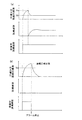
以下に本発明の実施の形態におけるレーザ発振装置の制御方法について図面によって説明する。図1は本発明の実施の形態におけるレーザ発振装置の放電電流のフィードバック制御を説明するための波形図である。
(Embodiment)
Hereinafter, a method for controlling a laser oscillation apparatus according to an embodiment of the present invention will be described with reference to the drawings. FIG. 1 is a waveform diagram for explaining feedback control of discharge current of the laser oscillation apparatus according to the embodiment of the present invention.
制御回路構成は前述の技術背景で述べた図2に示す制御回路構成と同じであるので、その構成詳細と基本的な動作の説明は省略し、本発明のポイントである放電電流のフィードバック制御による放電電流目標値設定器6からの信号、高電圧電源4の出力電圧、および放電電流の関係について図1(a)および図1(b)を参照しながら説明する。
Since the control circuit configuration is the same as the control circuit configuration shown in FIG. 2 described in the above technical background, the detailed configuration and description of the basic operation will be omitted, and the discharge current feedback control which is the point of the present invention will be omitted. The relationship between the signal from the discharge current target value setter 6, the output voltage of the high
図1(a)では電極3の酸化膜が放電に影響を与えない状態の場合を示している。以下、図1(a)を参照しながら詳細に説明する。
FIG. 1A shows a case where the oxide film of the
レーザ出力の開始時に、放電電流目標値設定器6から所望のレーザ出力に対応した放電電流目標値が信号として立ち上がり時間taの間だけ出力する。 At the start of laser output, the discharge current target value setter 6 outputs a discharge current target value corresponding to the desired laser output as a signal only during the rise time ta.
放電電流のフィードバック制御経路であるところの高電圧電源4の回路常数および、放電管1内のレーザ媒質ガスの組成や圧力などによる放電回路定数および、レーザ媒質ガスの組成や圧力などによる放電管1内で放電を開始するに必要な電圧であるところの放電開始電圧Vaにより、立ち上がり時間taは一定値として決定されるため、予め算出や測定により導き設定することが可能である。
その後、立下り時間tbの間、放電電流目標値設定器6の信号をゼロと設定して高電圧電源4の電圧の出力を停止する。
Thereafter, during the fall time tb, the signal of the discharge current target value setter 6 is set to zero and the output of the voltage of the high
高電圧電源4の回路定数およびレーザ媒質ガスの組成や圧力などによる放電回路定数および、レーザ媒質ガスの組成や圧力などによる放電を維持するための放電維持電圧Vbにより、立下り時間tbは一定値として決定されるため、予め算出や測定により導き設定することが可能である。
The fall time tb is a constant value due to the circuit constant of the high
その後、放電電流目標値設定器6は放電電流の目標値を設定して高電圧電源4からの電圧出力を再開して、放電電流を所望のレーザ出力に対応した値になるように放電電流をフィードバック制御する。
Thereafter, the discharge current target value setter 6 sets the target value of the discharge current and restarts the voltage output from the high-
この動作によれば、立下り時間tbの間、放電電流目標値設定器6の信号をゼロと設定して高電圧電源4の電圧の出力を停止しても、放電管1内の放電は維持継続されているため、技術背景で説明した従来例の図3(a)と同じ放電電流のフィードバック制御が可能である。
According to this operation, during the fall time tb, even if the signal of the discharge current target value setter 6 is set to zero and the output of the voltage of the high
図1(b)では電極3表面全体を酸化膜が覆い電気絶縁材として放電を妨げる場合での放電電流目標値設定器6からの信号と、高電圧電源4の出力電圧と、放電電流の関係を示している。以下、図1(b)を参照しながら詳細に説明する。
In FIG. 1B, the relationship between the signal from the discharge current target value setter 6, the output voltage of the high-
放電電流目標値設定器6の信号の出力方法は図1(a)を参照に説明した出力方法と同じである。しかしながら、電極3表面の酸化膜が放電を妨げているため立ち上がり時間taを経過した後、高電圧電源4の出力電圧が放電開始電圧Vaに到達しても放電せず放電電流は流れない。
The signal output method of the discharge current target value setter 6 is the same as the output method described with reference to FIG. However, since the oxide film on the surface of the
その後、立ち下がり時間tbの間は強制的に高電圧電源4の出力を停止するため、従来の様に高電圧電源4の過電圧保護機能などよりアラーム停止するという状態には至らない。
Thereafter, since the output of the high
その後、放電電流目標値設定器6は放電電流の目標値を設定して高電圧電源4からの電圧出力を再開するが、電極3には直前に高電圧が印加されているため酸化膜は脆くなっており、再度の高電圧印加によってついには酸化膜が一部破壊され放電が開始され放電電流のフィードバック制御は安定して実施されるためガスレーザ発振装置の継続使用ができ、信頼性の高い装置を得ることができる。
Thereafter, the discharge current target value setter 6 sets the target value of the discharge current and restarts the voltage output from the high
次にレーザ加工装置について説明する。 Next, a laser processing apparatus will be described.
従来の技術で図4を用いて説明したが、ワーク16を乗せる加工テーブル19と、加工テーブル19の移動とレーザ加工トーチ17の少なくとも一方を移動するX軸モータ20やY軸モータ21などの駆動手段と、この駆動手段を制御する数値制御装置(図示せず)と、レーザービーム9を、集光レンズ18を通過させてレーザを発生するレーザ加工装置に、上述した実施の形態におけるレーザ発振装置の制御方法およびその制御方法を用いたレーザ発信装置を構成とすることにより、レーザ加工装置の継続使用ができ、信頼性の高い装置を得ることができる。
As described in the prior art with reference to FIG. 4, the machining table 19 on which the
本発明は、放電励起するための電極の表面に経年的に酸化膜が生成されても安定した放電励起ができるため、ガスレーザ発振装置およびレーザ加工装置の継続使用ができ、信頼性の高い装置を提供できる。 The present invention enables stable discharge excitation even when an oxide film is formed on the surface of an electrode for discharge excitation over time, so that a gas laser oscillation apparatus and a laser processing apparatus can be used continuously, and a highly reliable apparatus is provided. Can be provided.
1 レーザ媒質ガスを内部に有する放電管
2 光共振器
3 電極
4 高電圧電源
5 放電電流検出器
6 放電電流目標値設定器
7 差動増幅器
8 加算器
9 レーザービーム
15 反射鏡
16 ワーク
17 トーチ
18 集光レンズ
19 加工テーブル
20 X軸モータ
21 Y軸モータ
DESCRIPTION OF
Claims (3)
Priority Applications (1)
| Application Number | Priority Date | Filing Date | Title |
|---|---|---|---|
| JP2009287124A JP2011129727A (en) | 2009-12-18 | 2009-12-18 | Control method for gas laser oscillator, the gas laser oscillator and laser processing device |
Applications Claiming Priority (1)
| Application Number | Priority Date | Filing Date | Title |
|---|---|---|---|
| JP2009287124A JP2011129727A (en) | 2009-12-18 | 2009-12-18 | Control method for gas laser oscillator, the gas laser oscillator and laser processing device |
Publications (1)
| Publication Number | Publication Date |
|---|---|
| JP2011129727A true JP2011129727A (en) | 2011-06-30 |
Family
ID=44292001
Family Applications (1)
| Application Number | Title | Priority Date | Filing Date |
|---|---|---|---|
| JP2009287124A Pending JP2011129727A (en) | 2009-12-18 | 2009-12-18 | Control method for gas laser oscillator, the gas laser oscillator and laser processing device |
Country Status (1)
| Country | Link |
|---|---|
| JP (1) | JP2011129727A (en) |
-
2009
- 2009-12-18 JP JP2009287124A patent/JP2011129727A/en active Pending
Similar Documents
| Publication | Publication Date | Title |
|---|---|---|
| US7599407B2 (en) | Laser control method, laser apparatus, laser treatment method used for the same, laser treatment apparatus | |
| CN102056703B (en) | Laser processing device and laser processing method | |
| KR101210653B1 (en) | Laser processing method and apparatus using electric field | |
| JP2013107089A (en) | Laser beam machining system having auxiliary control unit | |
| JP6367858B2 (en) | Laser processing apparatus and laser processing method for performing laser processing while suppressing reflected light | |
| CN110280914A (en) | A laser ultrasonic technology assisted pulse laser drilling device and method | |
| GB2485985A (en) | Laser Pulse Generation Method and Apparatus | |
| JP2017177174A (en) | Laser processing apparatus and laser processing method provided with pre-processing control unit | |
| Pallav et al. | Comparative assessment of the laser induced plasma micromachining and the micro-EDM processes | |
| KR20140115250A (en) | Laser processing apparatus and laser processing method | |
| JP2005118821A (en) | Ultrashort pulse laser beam machining method | |
| JP2015153917A (en) | Laser processing device | |
| KR101425337B1 (en) | Laser processing apparatus, processing control apparatus, and pulse frequency control method | |
| JPH08155670A (en) | Laser beam machine and its machining method | |
| JP6915073B2 (en) | Plasma ignition method and plasma generator | |
| JP6205603B2 (en) | Carbon dioxide laser device | |
| US8068520B2 (en) | Method for generating a laser pulse for the fine machining of workpieces using a fiber laser | |
| JP2006128374A (en) | Semiconductor laser-excited solid state laser | |
| JP3916734B2 (en) | Laser processing equipment | |
| JP6322801B2 (en) | Carbon dioxide laser excitation medium gas, marking apparatus using carbon dioxide laser, carbon dioxide laser generation method, marking method using carbon dioxide laser, and carbon dioxide laser light source | |
| JP4107158B2 (en) | Laser oscillation device and laser processing machine | |
| Wollermann-Windgasse et al. | rf-excited high power CO2-lasers for industrial material processing | |
| JPH01185987A (en) | Oscillation of pulse laser and apparatus therefor | |
| JPH0323274B2 (en) | ||
| JP2007163452A (en) | Device and method for regulating leakage vibration of piezoelectric vibrator |