JP2011133763A - Developing cartridge - Google Patents
Developing cartridge Download PDFInfo
- Publication number
- JP2011133763A JP2011133763A JP2009294591A JP2009294591A JP2011133763A JP 2011133763 A JP2011133763 A JP 2011133763A JP 2009294591 A JP2009294591 A JP 2009294591A JP 2009294591 A JP2009294591 A JP 2009294591A JP 2011133763 A JP2011133763 A JP 2011133763A
- Authority
- JP
- Japan
- Prior art keywords
- gear
- developing
- roller
- supply
- supply roller
- Prior art date
- Legal status (The legal status is an assumption and is not a legal conclusion. Google has not performed a legal analysis and makes no representation as to the accuracy of the status listed.)
- Pending
Links
- 238000011161 development Methods 0.000 claims abstract description 11
- 230000008878 coupling Effects 0.000 claims description 31
- 238000010168 coupling process Methods 0.000 claims description 31
- 238000005859 coupling reaction Methods 0.000 claims description 31
- 230000005540 biological transmission Effects 0.000 claims description 8
- 238000004804 winding Methods 0.000 claims description 5
- 230000002093 peripheral effect Effects 0.000 abstract description 35
- 238000012546 transfer Methods 0.000 description 7
- 238000003780 insertion Methods 0.000 description 6
- 230000037431 insertion Effects 0.000 description 6
- 238000000034 method Methods 0.000 description 6
- 230000008569 process Effects 0.000 description 5
- 230000007246 mechanism Effects 0.000 description 4
- 238000000926 separation method Methods 0.000 description 4
- 125000006850 spacer group Chemical group 0.000 description 4
- 230000015572 biosynthetic process Effects 0.000 description 2
- 230000006866 deterioration Effects 0.000 description 2
- 238000013459 approach Methods 0.000 description 1
- 230000008859 change Effects 0.000 description 1
- 238000010586 diagram Methods 0.000 description 1
- 238000010438 heat treatment Methods 0.000 description 1
- 239000000463 material Substances 0.000 description 1
- 238000012986 modification Methods 0.000 description 1
- 230000004048 modification Effects 0.000 description 1
- 238000000465 moulding Methods 0.000 description 1
- 238000003825 pressing Methods 0.000 description 1
- 239000011347 resin Substances 0.000 description 1
- 229920005989 resin Polymers 0.000 description 1
Images


Classifications
-
- G—PHYSICS
- G03—PHOTOGRAPHY; CINEMATOGRAPHY; ANALOGOUS TECHNIQUES USING WAVES OTHER THAN OPTICAL WAVES; ELECTROGRAPHY; HOLOGRAPHY
- G03G—ELECTROGRAPHY; ELECTROPHOTOGRAPHY; MAGNETOGRAPHY
- G03G15/00—Apparatus for electrographic processes using a charge pattern
- G03G15/06—Apparatus for electrographic processes using a charge pattern for developing
- G03G15/08—Apparatus for electrographic processes using a charge pattern for developing using a solid developer, e.g. powder developer
- G03G15/0822—Arrangements for preparing, mixing, supplying or dispensing developer
- G03G15/0865—Arrangements for supplying new developer
- G03G15/0867—Arrangements for supplying new developer cylindrical developer cartridges, e.g. toner bottles for the developer replenishing opening
-
- G—PHYSICS
- G03—PHOTOGRAPHY; CINEMATOGRAPHY; ANALOGOUS TECHNIQUES USING WAVES OTHER THAN OPTICAL WAVES; ELECTROGRAPHY; HOLOGRAPHY
- G03G—ELECTROGRAPHY; ELECTROPHOTOGRAPHY; MAGNETOGRAPHY
- G03G15/00—Apparatus for electrographic processes using a charge pattern
- G03G15/06—Apparatus for electrographic processes using a charge pattern for developing
- G03G15/08—Apparatus for electrographic processes using a charge pattern for developing using a solid developer, e.g. powder developer
- G03G15/0806—Apparatus for electrographic processes using a charge pattern for developing using a solid developer, e.g. powder developer on a donor element, e.g. belt, roller
- G03G15/0808—Apparatus for electrographic processes using a charge pattern for developing using a solid developer, e.g. powder developer on a donor element, e.g. belt, roller characterised by the developer supplying means, e.g. structure of developer supply roller
-
- G—PHYSICS
- G03—PHOTOGRAPHY; CINEMATOGRAPHY; ANALOGOUS TECHNIQUES USING WAVES OTHER THAN OPTICAL WAVES; ELECTROGRAPHY; HOLOGRAPHY
- G03G—ELECTROGRAPHY; ELECTROPHOTOGRAPHY; MAGNETOGRAPHY
- G03G15/00—Apparatus for electrographic processes using a charge pattern
- G03G15/06—Apparatus for electrographic processes using a charge pattern for developing
- G03G15/08—Apparatus for electrographic processes using a charge pattern for developing using a solid developer, e.g. powder developer
- G03G15/0822—Arrangements for preparing, mixing, supplying or dispensing developer
- G03G15/0865—Arrangements for supplying new developer
-
- G—PHYSICS
- G03—PHOTOGRAPHY; CINEMATOGRAPHY; ANALOGOUS TECHNIQUES USING WAVES OTHER THAN OPTICAL WAVES; ELECTROGRAPHY; HOLOGRAPHY
- G03G—ELECTROGRAPHY; ELECTROPHOTOGRAPHY; MAGNETOGRAPHY
- G03G21/00—Arrangements not provided for by groups G03G13/00 - G03G19/00, e.g. cleaning, elimination of residual charge
- G03G21/16—Mechanical means for facilitating the maintenance of the apparatus, e.g. modular arrangements
- G03G21/1642—Mechanical means for facilitating the maintenance of the apparatus, e.g. modular arrangements for connecting the different parts of the apparatus
- G03G21/1647—Mechanical connection means
Landscapes
- Physics & Mathematics (AREA)
- General Physics & Mathematics (AREA)
- Dry Development In Electrophotography (AREA)
- Electrophotography Configuration And Component (AREA)
Abstract
【課題】供給ローラの周速を大きく変更することができ、かつ、現像ローラ駆動ギヤおよび供給ローラ駆動ギヤに駆動力を伝達するギヤ部の摩耗の度合いを下げることができる、現像カートリッジを提供する。
【解決手段】現像ローラ11には、現像ギヤ71が連結されている。供給ローラ37には、供給ギヤ72が連結されている。また、現像カートリッジ32には、現像ギヤ71および供給ギヤ72に駆動力を伝達するための入力ギヤ70が備えられている。入力ギヤ70は、第1ギヤ部75および第2ギヤ部76を備え、左右方向に延びるギヤ軸線を中心に回転可能に設けられている。現像ギヤ71および供給ギヤ72は、それぞれ第1ギヤ部75および第2ギヤ部76に噛合している。
【選択図】図7There is provided a developing cartridge capable of greatly changing the peripheral speed of a supply roller and reducing the degree of wear of a developing roller driving gear and a gear portion for transmitting driving force to the supplying roller driving gear. .
A developing gear is connected to the developing roller. A supply gear 72 is connected to the supply roller 37. Further, the developing cartridge 32 is provided with an input gear 70 for transmitting a driving force to the developing gear 71 and the supply gear 72. The input gear 70 includes a first gear portion 75 and a second gear portion 76, and is provided so as to be rotatable about a gear axis extending in the left-right direction. The development gear 71 and the supply gear 72 mesh with the first gear portion 75 and the second gear portion 76, respectively.
[Selection] Figure 7
Description
本発明は、画像形成装置の装置本体に着脱可能な現像カートリッジに関する。 The present invention relates to a developing cartridge that can be attached to and detached from an apparatus body of an image forming apparatus.
レーザプリンタなどの電子写真方式の画像形成装置には、静電潜像が形成される感光ドラムと、その感光ドラムに形成される静電潜像を現像するための現像カートリッジとが備えられている。
現像カートリッジには、現像ローラと、現像ローラにトナーを供給するための供給ローラとが備えられている。現像カートリッジの一方の側壁には、現像ローラおよび供給ローラを駆動させるためのギヤ機構部が設けられている。ギヤ機構部には、装置本体から駆動力が入力される入力ギヤと、現像ローラの現像ローラ軸の端部に取り付けられ、入力ギヤに噛合する現像ローラ駆動ギヤと、供給ローラの供給ローラ軸の端部に取り付けられ、入力ギヤに噛合する供給ローラ駆動ギヤとが備えられている。すなわち、現像ローラの現像ローラ軸の端部に取り付けられる現像ローラ駆動ギヤと、供給ローラの供給ローラ軸の端部に取り付けられる供給ローラ駆動ギヤとは、装置本体から駆動力が入力される入力ギヤの同じギヤ歯に噛合している。
An electrophotographic image forming apparatus such as a laser printer includes a photosensitive drum on which an electrostatic latent image is formed, and a developing cartridge for developing the electrostatic latent image formed on the photosensitive drum. .
The developing cartridge includes a developing roller and a supply roller for supplying toner to the developing roller. A gear mechanism for driving the developing roller and the supply roller is provided on one side wall of the developing cartridge. The gear mechanism includes an input gear to which driving force is input from the apparatus main body, a developing roller driving gear that is attached to an end of the developing roller shaft of the developing roller and meshes with the input gear, and a supply roller shaft of the supplying roller. A supply roller driving gear attached to the end and meshing with the input gear is provided. That is, the developing roller driving gear attached to the end of the developing roller shaft of the developing roller and the supply roller driving gear attached to the end of the supplying roller shaft of the supplying roller are an input gear to which driving force is input from the apparatus main body. Mesh with the same gear teeth.
画像形成時には、装置本体から入力ギヤに駆動力が入力されて、入力ギヤが回転される。そして、入力ギヤから現像ローラ駆動ギヤおよび供給ローラ駆動ギヤに駆動力が伝達されることにより、現像ローラ駆動ギヤを介して現像ローラが回転されるとともに、供給ローラ駆動ギヤを介して供給ローラが回転される。 At the time of image formation, a driving force is input from the apparatus main body to the input gear, and the input gear is rotated. When the driving force is transmitted from the input gear to the developing roller driving gear and the supply roller driving gear, the developing roller is rotated via the developing roller driving gear, and the supplying roller is rotated via the supply roller driving gear. Is done.
トナーの劣化を防止するために、供給ローラの周速を下げ、供給ローラと現像ローラとの間で生じる摩擦を小さくすることが考えられる。たとえば、供給ローラ駆動ギヤのギヤ径を大きくすることにより、供給ローラの周速を下げることができる。
供給ローラから現像ローラにトナーを良好に供給するために、現像ローラと供給ローラとは、一定のニップ幅で接している。このニップ幅は、現像ローラおよび供給ローラの径ならびに現像ローラ軸と供給ローラ軸との軸間距離により決まる。そのため、現像ローラおよび供給ローラの径ならびに現像ローラ軸と供給ローラ軸との軸間距離を変更して、供給ローラの周速を下げることは容易に行うことができない。また、現像ローラの周速(回転速度)は、現像プロセスに最も影響する因子であるため、所望の周速を維持すべく、現像ローラ駆動ギヤのギヤ径も容易に変更することができない。そこで、供給ローラの周速を下げるには、供給ローラ駆動ギヤのギヤ径または入力ギヤの位置を変更することが考えられるが、スペース的な制約もあり、供給ローラの周速を下げるには限界がある。
In order to prevent the deterioration of the toner, it is conceivable to reduce the friction generated between the supply roller and the developing roller by reducing the peripheral speed of the supply roller. For example, the peripheral speed of the supply roller can be reduced by increasing the gear diameter of the supply roller drive gear.
In order to satisfactorily supply toner from the supply roller to the development roller, the development roller and the supply roller are in contact with each other with a constant nip width. The nip width is determined by the diameters of the developing roller and the supply roller and the distance between the developing roller shaft and the supply roller shaft. For this reason, it is not possible to easily reduce the peripheral speed of the supply roller by changing the diameters of the development roller and the supply roller and the distance between the development roller shaft and the supply roller shaft. Further, since the peripheral speed (rotational speed) of the developing roller is a factor that most affects the developing process, the gear diameter of the developing roller drive gear cannot be easily changed in order to maintain a desired peripheral speed. Therefore, to reduce the peripheral speed of the supply roller, it is conceivable to change the gear diameter of the supply roller drive gear or the position of the input gear. However, there is a space limitation, and there is a limit to decrease the peripheral speed of the supply roller. There is.
また、入力ギヤに現像ローラ駆動ギヤおよび供給ローラ駆動ギヤの両方が噛合するため、入力ギヤのギヤ歯が摩耗しやすい。入力ギヤのギヤ歯が摩耗すると、現像ローラを安定して駆動することができず、現像ローラにより形成されるトナー像に乱れが生じるおそれがある。
本発明の目的は、供給ローラの周速を大きく変更することができ、かつ、現像ローラ駆動ギヤおよび供給ローラ駆動ギヤに駆動力を伝達するギヤ部の摩耗の度合いを下げることができる、現像カートリッジを提供することである。
Further, since both the developing roller driving gear and the supply roller driving gear mesh with the input gear, the gear teeth of the input gear are likely to wear. If the gear teeth of the input gear are worn, the developing roller cannot be driven stably, and the toner image formed by the developing roller may be disturbed.
An object of the present invention is to provide a developing cartridge capable of greatly changing the peripheral speed of the supply roller and reducing the degree of wear of the developing roller driving gear and the gear portion that transmits the driving force to the supplying roller driving gear. Is to provide.
前記の目的を達成するため、本発明は、画像形成装置の装置本体に着脱可能な現像カートリッジであって、所定方向に延びる現像ローラ軸線を中心に回転可能に設けられる現像ローラと、前記所定方向に延びる供給ローラ軸線を中心に回転可能に設けられ、現像ローラに現像剤を供給するための供給ローラと、前記現像ローラに連結される現像ローラ駆動ギヤと、前記供給ローラに連結される供給ローラ駆動ギヤと、前記所定方向に延びるギヤ軸線を中心に回転可能に設けられ、前記現像ローラ駆動ギヤと噛合する第1ギヤ部および前記供給ローラ駆動ギヤと噛合する第2ギヤ部を一体的に有し、前記現像ローラ駆動ギヤおよび前記供給ローラ駆動ギヤに駆動力を伝達するための駆動力伝達ギヤとを備えることを特徴としている。 In order to achieve the above object, the present invention provides a developing cartridge that can be attached to and detached from an apparatus main body of an image forming apparatus, the developing roller provided rotatably about a developing roller axis extending in a predetermined direction, and the predetermined direction. A supply roller for supplying a developer to the developing roller, a developing roller driving gear connected to the developing roller, and a supplying roller connected to the supplying roller A drive gear is provided integrally with a first gear portion meshing with the developing roller driving gear and a second gear portion meshing with the supply roller driving gear, which is rotatably provided around a gear axis extending in the predetermined direction. And a driving force transmission gear for transmitting a driving force to the developing roller driving gear and the supply roller driving gear.
本発明によれば、現像カートリッジには、現像ローラおよび供給ローラが備えられている。現像ローラは、所定方向に延びる現像ローラ軸線を中心に回転可能に設けられている。現像ローラには、現像ローラ駆動ギヤが連結されている。供給ローラは、所定方向に延びる供給ローラ軸線を中心に回転可能に設けられている。供給ローラには、供給ローラ駆動ギヤが連結されている。また、現像カートリッジには、現像ローラ駆動ギヤおよび供給ローラ駆動ギヤに駆動力を伝達するための駆動力伝達ギヤが備えられている。駆動力伝達ギヤは、第1ギヤ部および第2ギヤ部を備え、所定方向に延びるギヤ軸線を中心に回転可能に設けられている。現像ローラ駆動ギヤおよび供給ローラ駆動ギヤは、それぞれ第1ギヤ部および第2ギヤ部に噛合している。そのため、第2ギヤ部および供給ローラ駆動ギヤの各ギヤ径を変更することにより、現像ローラの周速を変更することなく、供給ローラの周速を大きく変更することができる。 According to the present invention, the developing cartridge is provided with a developing roller and a supply roller. The developing roller is provided to be rotatable about a developing roller axis extending in a predetermined direction. A developing roller driving gear is connected to the developing roller. The supply roller is provided to be rotatable about a supply roller axis extending in a predetermined direction. A supply roller driving gear is connected to the supply roller. The developing cartridge is provided with a driving force transmission gear for transmitting a driving force to the developing roller driving gear and the supply roller driving gear. The driving force transmission gear includes a first gear portion and a second gear portion, and is provided to be rotatable around a gear axis extending in a predetermined direction. The developing roller driving gear and the supply roller driving gear mesh with the first gear portion and the second gear portion, respectively. Therefore, by changing the gear diameters of the second gear portion and the supply roller drive gear, the peripheral speed of the supply roller can be greatly changed without changing the peripheral speed of the developing roller.
また、現像ローラ駆動ギヤと供給ローラ駆動ギヤとが別々のギヤ部に噛合するので、現像ローラ駆動ギヤおよび供給ローラ駆動ギヤが同一のギヤ部に噛合する構成と比べて、ギヤ部の摩耗の度合いを下げることができる。 In addition, since the developing roller driving gear and the supply roller driving gear mesh with separate gear portions, the degree of wear of the gear portion compared to the configuration in which the developing roller driving gear and the supply roller driving gear mesh with the same gear portion. Can be lowered.
以下では、本発明の実施形態について、添付図面を参照しながら詳細に説明する。
1.プリンタの全体構成
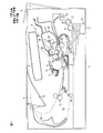
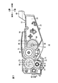
図1に示すように、画像形成装置の一例としてのプリンタ1は、装置本体の一例としての本体ケーシング2を備えている。
本体ケーシング2内の中央部には、プロセスカートリッジ3が設けられている。プロセスカートリッジ3は、本体ケーシング2の一方側壁に設けられたフロントカバー4を介して、本体ケーシング2に対して着脱可能に装着される。
Hereinafter, embodiments of the present invention will be described in detail with reference to the accompanying drawings.
1. Overall Configuration of Printer As shown in FIG. 1, a
A process cartridge 3 is provided at the center of the main casing 2. The process cartridge 3 is detachably attached to the main body casing 2 via a front cover 4 provided on one side wall of the main body casing 2.
なお、以下の説明において、本体ケーシング2におけるフロントカバー4が設けられている側を前側とし、その反対側を後側とする。また、プリンタ1を前側から見たときを左右の基準とする。また、後述する現像カートリッジ32については、本体ケーシング2に装着された状態を前後左右の基準とする。
プロセスカートリッジ3は、ドラムカートリッジ31と、そのドラムカートリッジ31に着脱自在に装着される現像カートリッジ32とを備えている。
In the following description, the side of the main casing 2 where the front cover 4 is provided is the front side, and the opposite side is the rear side. In addition, when the
The process cartridge 3 includes a
ドラムカートリッジ31には、感光ドラム6が回転可能に設けられている。また、ドラムカートリッジ31には、帯電器7および転写ローラ9が設けられている。
感光ドラム6は、図1の紙面に垂直な方向に延びる軸線を中心に回転可能に設けられている。
帯電器7は、スコロトロン型帯電器であり、感光ドラム6の周面に対して間隔を空けて対向配置されている。
In the
The photosensitive drum 6 is provided to be rotatable around an axis extending in a direction perpendicular to the paper surface of FIG.
The charger 7 is a scorotron charger, and is disposed so as to face the circumferential surface of the photosensitive drum 6 with a space therebetween.
現像カートリッジ32は、トナーを収容する筐体の一例としての現像筐体10を備えている。現像筐体10の内部には、現像室33と現像室33に供給するトナーが収容されるトナー収容室34とが互いに隣接して形成されている。
現像室33内には、現像ローラ11および供給ローラ37が回転可能に保持されている。
The developing
In the developing chamber 33, the developing
現像ローラ11は、その周面の一部が現像筐体10の後端部から露出している。また、供給ローラ37は、その周面が現像ローラ11の前側部分に接触している。そして、現像カートリッジ32は、現像ローラ11における現像筐体10から露出した部分が感光ドラム6の周面と接触するようにドラムカートリッジ31に装着されている。
トナー収容室34内には、アジテータ25が回転可能に保持されている。トナー収容室34内のトナーは、アジテータ25の回転により攪拌されつつ、現像室33内に供給される。
A part of the peripheral surface of the developing
An
転写ローラ9は、感光ドラム6の下方において、感光ドラム6の回転軸線と平行な軸線を中心に回転可能に設けられ、その周面が感光ドラム6の周面に接触するように配置されている。
本体ケーシング2内において、プロセスカートリッジ3の上方には、レーザなどを備える露光器5が配置されている。
The transfer roller 9 is provided below the photosensitive drum 6 so as to be rotatable about an axis parallel to the rotational axis of the photosensitive drum 6, and is arranged so that the peripheral surface thereof is in contact with the peripheral surface of the photosensitive drum 6. .
In the main casing 2, an exposure unit 5 having a laser or the like is disposed above the process cartridge 3.
画像形成時には、感光ドラム6が図1における時計回りに一定速度で回転される。感光ドラム6の回転に伴って、感光ドラム6の周面(表面)は、帯電器7からの放電により、一様に帯電される。一方、プリンタ1に接続されたパーソナルコンピュータ(図示せず)から受信する画像データに基づいて、露光器5からレーザビームが出射される。レーザビームは、帯電器7と現像カートリッジ32との間を通り、一様に正帯電された感光ドラム6の周面に照射される。これにより、感光ドラム6の周面が選択的に露光され、その露光された部分から電荷が選択的に除去されて、感光ドラム6の周面に静電潜像が形成される。感光ドラム6の回転により、静電潜像が現像ローラ11に対向すると、現像ローラ11から静電潜像にトナーが供給される。これによって、感光ドラム6の周面にトナー像が形成される。
At the time of image formation, the photosensitive drum 6 is rotated at a constant speed clockwise in FIG. As the photosensitive drum 6 rotates, the peripheral surface (surface) of the photosensitive drum 6 is uniformly charged by the discharge from the charger 7. On the other hand, a laser beam is emitted from the exposure device 5 based on image data received from a personal computer (not shown) connected to the
本体ケーシング2の底部には、用紙Pを収容する給紙カセット12が配置されている。給紙カセット12の上方には、給紙カセット12から用紙を送り出すためのピックアップローラ13が設けられている。
また、本体ケーシング2内には、側面視S字状の搬送路14が形成されている。この搬送路14は、給紙カセット12から感光ドラム6と転写ローラ9との間を経由して、本体ケーシング2の上面に形成された排紙トレイ15に至る。搬送路14上には、互いに対向配置される分離ローラ16および分離パッド17、1対の給紙ローラ18、1対のレジストローラ19ならびに1対の排紙ローラ20が設けられている。
A
Further, a conveying
給紙カセット12から送り出された用紙Pは、分離ローラ16と分離パッド17との間を通過し、その際に1枚ずつに捌かれる。その後、用紙Pは、給紙ローラ18により、レジストローラ19に向けて搬送される。そして、その用紙Pは、レジストローラ19によるレジスト後に、レジストローラ19により、感光ドラム6と転写ローラ9との間に向けて搬送される。
The paper P sent out from the
感光ドラム6の周面上のトナー像は、感光ドラム6の回転により、感光ドラム6と転写ローラ9との間を通過する用紙Pと対向したときに、転写ローラ9により電気的に引き寄せられて、用紙Pに転写される。
搬送路14上には、転写ローラ9に対して用紙Pの搬送方向の下流側に、定着器21が設けられている。トナー像が転写された用紙Pは、搬送路14を搬送されて、定着器21を通過する。定着器21では、加熱および加圧により、トナー像が画像となって用紙Pに定着される。
The toner image on the circumferential surface of the photosensitive drum 6 is electrically attracted by the transfer roller 9 when the photosensitive drum 6 rotates and faces the paper P passing between the photosensitive drum 6 and the transfer roller 9. And transferred to the paper P.
A fixing
このプリンタ1は、動作モードとして、用紙Pの片面に画像(トナー像)を形成する片面モードと、用紙Pの一方面に画像を形成した後、その用紙Pの一方面と反対の他方面に画像を形成する両面モードとを有している。
片面モードでは、一方面に画像が形成された用紙Pは、排紙ローラ20により、排紙トレイ15に排出される。
The
In the single-sided mode, the paper P on which an image is formed on one side is discharged to the
両面モードを実現するための構成として、本体ケーシング2内には、反転搬送路22が形成されている。反転搬送路22は、排紙ローラ20の近傍から搬送路14と給紙カセット12との間を延び、搬送路14における給紙ローラ18とレジストローラ19との間の部分に接続されている。反転搬送路22上には、1対の第1反転搬送ローラ23および1対の第2反転搬送ローラ24が設けられている。
As a configuration for realizing the double-sided mode, a
両面モードでは、用紙Pの一方面に画像が形成された後、その用紙Pは、排紙トレイ15に排出されずに、反転搬送路22に送り込まれる。そして、用紙Pは、第1反転搬送ローラ23および第2反転搬送ローラ24により、反転搬送路22を搬送され、その表裏が反転されて、画像が形成されていない他方面が感光ドラム6の周面と対向する姿勢で搬送路14に送り込まれる。そして、用紙Pの他方面に画像が形成されることにより、用紙Pの両面への画像の形成が達成される。
2.現像カートリッジ
現像カートリッジ32の現像筐体10は、後側が開放されたボックス形状に形成されている。
In the double-side mode, after an image is formed on one side of the paper P, the paper P is sent to the
2. Developing Cartridge The developing
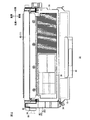
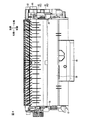
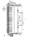
図2に示すように、現像筐体10は、左右方向に対向する1対の側壁36を備えている。図2,3に示すように、両側壁36間には、上壁38および下壁39が架設されている。上壁38および下壁39は、現像筐体10の前端部で連結されている。この連結部分には、把持部40が設けられている。把持部40は、現像筐体10の前端部から前側上方に向けて延び、その前側部分が開放された断面コ字状に形成されている。
As shown in FIG. 2, the
現像ローラ11および供給ローラ37(図1参照)は、両側壁36間に回転可能に保持されている。
(1)現像ローラ
図2,3に示すように、現像ローラ11は、両側壁36の後端部間に配置されている。図5に示すように、現像ローラ11は、左右方向に延びる円筒状の現像ローラ本体45と、現像ローラ本体45の中心軸線に沿って延びる現像ローラ軸46とを備えている。
The developing
(1) Developing Roller As shown in FIGS. 2 and 3, the developing
現像ローラ軸46の両端部は、現像筐体10の両側壁36を貫通している。
(2)供給ローラ
図1に示すように、供給ローラ37は、現像ローラ11に対して前側下方の位置に配置されている。図5に示すように、供給ローラ37は、左右方向に延びる円筒状の供給ローラ本体47と、供給ローラ本体47の中心軸線に沿って延びる供給ローラ軸48とを備えている。
Both end portions of the developing
(2) Supply Roller As shown in FIG. 1, the
供給ローラ本体47の周面は、現像ローラ本体45の周面に対して前側下方から接触している。
供給ローラ軸48の両端部は、現像筐体10の両側壁36を貫通している。
(3)軸受部材
図5に示すように、右側の側壁36の外側には、右側軸受部材50が設けられている。現像ローラ軸46および供給ローラ軸48の右端部は、右側軸受部材50を介して、右側の側壁36に相対回転可能に支持されている。すなわち、右側軸受部材50は、現像ローラ軸46の右端部および供給ローラ軸48の右端部を一括して保持している。
The peripheral surface of the supply roller main body 47 is in contact with the peripheral surface of the developing roller
Both end portions of the
(3) Bearing Member As shown in FIG. 5, the
図5に示すように、左側の側壁36の外側には、現像軸受部材51および供給軸受部材52が設けられている。
現像軸受部材51は、円筒状に形成され、左側の側壁36に相対回転不能に取り付けられている。現像ローラ軸46は、現像軸受部材51の内側に挿通されている。これにより、現像ローラ軸46の左端部は、現像軸受部材51を介して、左側の側壁36に相対回転可能に支持されている。
As shown in FIG. 5, a developing bearing
The
供給軸受部材52は、係止部53、鍔部54およびスペーサ55を一体的に備えている。
係止部53は、略円筒状に形成され、左側の側壁36に相対回転不能に取り付けられている。係止部53の右端部には、供給ローラ軸48に近づくように屈曲された鉤状部56が形成されている。供給ローラ軸48には、鉤状部56と対向する位置に、その周面から周方向に沿って切り欠かれた被係止溝57が形成されている。この被係止溝57に鉤状部56が入り込むことにより、供給ローラ軸48がその軸線方向(左右方向)に位置決めされる。
The
The locking
図9に示すように、鍔部54は、略四角形状に形成されている。鍔部54は、左側の側壁36に対して左側から当接している。
図5,9に示すように、スペーサ55は、円筒状に形成されている。スペーサ55の内側には、供給ローラ軸48が挿通されている。
これにより、供給ローラ軸48の左端部は、供給軸受部材52を介して、左側の側壁36に相対回転不能に支持されている。
(4)ギヤ機構
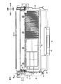
図2〜4に示すように、現像カートリッジ32の左端部には、ギヤカバー42が取り付けられている。
(4−1)ギヤカバー
ギヤカバー42は、左側の側壁36に左側から対向する側板60と、側板60の周縁部から現像筐体10側に向けて延びる周板61とを一体的に備えている。
As shown in FIG. 9, the
As shown in FIGS. 5 and 9, the
Thereby, the left end portion of the
(4) Gear Mechanism As shown in FIGS. 2 to 4, a
(4-1) Gear Cover The
図3に示すように、側板60は、前後方向および上下方向に延びる板状をなし、現像室33およびトナー収容室34(図1参照)のほぼ全域と対向するサイズに形成されている。
図3,5に示すように、現像ローラ軸46の左端部は、ギヤカバー42から左方に突出しており、その突出した部分には、円筒状のカラー部材62が取り付けられている。
As shown in FIG. 3, the
As shown in FIGS. 3 and 5, the left end portion of the developing
また、側板60の前端部および後端部には、2つのねじ孔(図示せず)が形成されている。これらのねじ孔を介して、ねじ65が左側の側壁36に螺着されることにより、側板60が左側の側壁36(現像筐体10)に固定される。
また、カラー部材62に対して前側上方の位置には、カップリング挿入部66が形成されている。カップリング挿入部66は、左方に突出する円筒状をなしている。カップリング挿入部66には、後述するカップリング部材77が相対回転可能に挿入される。
Further, two screw holes (not shown) are formed in the front end portion and the rear end portion of the
A
図6に破線で示すように、周板61(ギヤカバー42)の右端部は、左側の側壁36にと上下方向に対向するようにオーバーラップしている。
(4−2)ギヤ
図6に示すように、ギヤカバー42と左側の側板36との間には、駆動伝達ギヤの一例としての入力ギヤ70、現像ローラ駆動ギヤの一例としての現像ギヤ71、供給ローラ駆動ギヤの一例としての供給ギヤ72、連結ギヤ73およびアジテータギヤ74が設けられている。各ギヤ70〜74は、左右方向に沿った回転軸線を中心に回転可能に設けられている。
(4−2−1)入力ギヤ
図7に示すように、入力ギヤ70は、現像筐体10の前端部の上側に配置されている。入力ギヤ70は、左側の側壁36に相対回転可能に支持されている。図6〜9に示すように、入力ギヤ70は、第1ギヤ部75、第2ギヤ部76およびカップリング部材77を一体的に備えている。第1ギヤ部75、第2ギヤ部76およびカップリング部材77は、側壁36側からこの順に並んで配置されている。
As indicated by a broken line in FIG. 6, the right end portion of the peripheral plate 61 (gear cover 42) overlaps the
(4-2) Gear As shown in FIG. 6, between the
(4-2-1) Input Gear As shown in FIG. 7, the
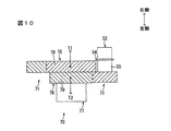
図10に示すように、第1ギヤ部75の周面には、所定のつる巻き線に沿った歯すじを有する第1はすば78が形成されている。
第2ギヤ部76は、第1ギヤ部75よりも小径に形成されている。第2ギヤ部76の周面には、第1ギヤ部75とは逆向きのつる巻き線に沿った歯すじを有する第2はすば79が形成されている。
As shown in FIG. 10, a first helical 78 having a tooth line along a predetermined helical winding is formed on the peripheral surface of the
The
言い換えれば、第1はすば78と第2はすば79とは、互いに向きが異なるつる巻き線に沿った歯すじを有している。
図3,7に示すように、カップリング部材77の左側面には、結合部80が形成されている。結合部80は、カップリング部材77の左側面から右方に掘り下がって形成され、円の一部がその周囲から扇状に部分的に切り欠かれた形状を有している。
(4−2−2)現像ギヤ
図7〜9に示すように、現像ギヤ71は、入力ギヤ70に対して後側下方の位置に配置されている。現像ギヤ71は、現像ローラ軸46に相対回転不能に取り付けられている。現像ローラ軸46の左端部は、現像ギヤ71から左方に突出している。そして、その突出部分には、側面視C字状の止め具81が取り付けられている。これにより、現像ギヤ71の現像ローラ軸46の軸線方向(左右方向)の移動が規制されている。
In other words, the first helical 78 and the second helical 79 have tooth traces along helical windings having different directions.
As shown in FIGS. 3 and 7, a
(4-2-2) Developing Gear As shown in FIGS. 7 to 9, the developing
現像ギヤ71は、入力ギヤ70の第1ギヤ部75に噛合している。
(4−2−3)供給ギヤ
供給ギヤ72は、入力ギヤ70に対して下方の位置に配置されている。図5,9に示すように、供給ギヤ72は、供給軸受部材52のスペーサ55の外側において、供給ローラ軸48まわりに相対回転不能に取り付けられている。具体的には、供給ローラ軸48の左端部は、その周面の一部が切り落とされた断面D字状にDカット加工されている。そして、そのD字状部分が供給ギヤ72に挿入されることにより、供給ローラ軸48に供給ギヤ72が相対回転不能に取り付けられる。供給ローラ軸48の左端部は、供給ギヤ72に挿入された状態で、供給ギヤ72の左端面よりも内側(右側)に配置されている。
The
(4-2-3) Supply Gear The
図7〜9に示すように、供給ギヤ72は、入力ギヤ70の第2ギヤ部76に噛合している。
(4−2−4)連結ギヤ
図7〜9に示すように、連結ギヤ73は、入力ギヤ70に対して前方の位置に配置されている。連結ギヤ73は、周面にギヤ歯を有する第1ギヤ部85および第2ギヤ部86を一体的に備えている。第1ギヤ部85および第2ギヤ部86は、側壁36側からこの順に並んで配置されている。
As shown in FIGS. 7 to 9, the
(4-2-4) Connection Gear As shown in FIGS. 7 to 9, the
第1ギヤ部85は、円筒状に形成されている。左側の側壁36には、左方に突出する支持突起(図示せず)が突設されている。第1ギヤ部85の内側に支持突起が相対回転可能に挿入されることにより、連結ギヤ73は、左側の側壁36に相対回転可能に支持されている。
第2ギヤ部86は、第1ギヤ部85よりも大きな外径を有している。第2ギヤ部86は、入力ギヤ70の第2ギヤ部76に噛合している。
(4−2−5)アジテータギヤ
図7に示すように、アジテータギヤ74は、連結ギヤ73に対して前側下方の位置に配置されている。アジテータギヤ74は、支持部88およびギヤ部89を一体的に備えている。
The
The
(4-2-5) Agitator Gear As shown in FIG. 7, the
図7,9に示すように、支持部88は、円筒状に形成されている。支持部88の中心部には、断面D字状の軸挿入孔90がその軸線方向に貫通して形成されている。軸挿入孔90には、アジテータ軸91が相対回転不能に挿入される。具体的には、アジテータ軸91の左端部は、その周面の一部が切り落とされた断面D字状にDカット加工されている。そして、そのD字状部分が軸挿入孔90に挿入されることにより、アジテータ軸91にアジテータギヤ74が相対回転不能に取り付けられる。アジテータ軸91は、図1に示すアジテータ25に連結されている。これにより、アジテータギヤ74が回転すると、アジテータ軸91を介して、アジテータ25が回転する。
As shown in FIGS. 7 and 9, the
ギヤ部89は、連結ギヤ73の第1ギヤ部85に噛合している。
4.本体ケーシング内の構成
図2に仮想線で示すように、本体ケーシング2内には、駆動部材の一例としての本体側カップリング99が設けられている。本体側カップリング99は、現像カートリッジ32が本体ケーシング2(図1参照)に装着された状態で、カップリング部材77(図7参照)に左方から対向する位置に配置されている。本体側カップリング99は、右方に突出する図示しない係合突起を有している。
The
4). Configuration in Main Body Casing As shown by phantom lines in FIG. 2, a main body side coupling 99 as an example of a drive member is provided in the main body casing 2. The main body side coupling 99 is disposed at a position facing the coupling member 77 (see FIG. 7) from the left in a state where the developing
現像カートリッジ32の本体ケーシング2内への装着が完了した後、本体側カップリング99が右方に進出されると、本体側カップリング99の係合突起がカップリング部材77の結合部80(図7参照)内に挿入される。本体側カップリング99がさらに右方に進出されることにより、カップリング部材77が右方に押圧される。これにより、入力ギヤ70の左右方向の位置決めが達成される。その後、本体側カップリング99に図示しないモータからの回転駆動力が入力されると、本体側カップリング99を介して、カップリング部材77が回転する。
After the mounting of the developing
なお、本体側カップリング99の右方への進出は、図1に示すフロントカバー4の閉止動作に連動させることができる。このような連動動作は、周知であるため、連動機構についての詳細な説明を省略する。
5.ギヤの駆動
本体側カップリング99がカップリング部材77に連結され、入力ギヤ70に回転駆動力が入力されると、入力ギヤ70は、図7における時計回り方向に回転する。
The advancement of the main body side coupling 99 to the right can be interlocked with the closing operation of the front cover 4 shown in FIG. Since such an interlocking operation is well known, detailed description of the interlocking mechanism is omitted.
5. Gear Driving When the main body side coupling 99 is coupled to the
入力ギヤ70の第1ギヤ部75には、現像ギヤ71が噛合している。そのため、現像ギヤ71は、入力ギヤ70の回転に伴って、図7における反時計回り方向に回転する。これにより、現像ギヤ71を介して、現像ローラ11(図1参照)が図1における反時計回り方向に回転する。
また、図10に示すように、入力ギヤ70の第1ギヤ部75に形成された第1はすば78により、入力ギヤ70には、右側に向かう方向のスラスト力T1が発生する。
The developing
Also, as shown in FIG. 10, a thrust force T <b> 1 in the right direction is generated in the
図7に示すように、入力ギヤ70の第2ギヤ部76には、供給ギヤ72が噛合している。そのため、供給ギヤ72は、入力ギヤ70の回転に伴って、図7における反時計回り方向に回転する。これにより、供給ギヤ72を介して、供給ローラ37(図1参照)が図1における反時計回り方向に回転する。
このとき、図10に示すように、入力ギヤ70の第2ギヤ部76に形成された第2はすば79により、入力ギヤ70には、左側に向かう方向のスラスト力T2が発生する。
As shown in FIG. 7, the
At this time, as shown in FIG. 10, the
図7に示すように、第1ギヤ部75よりも第2ギヤ部76のギヤ径が小さいため、第1ギヤ部75に噛合する現像ギヤ71の回転速度よりも、第2ギヤ部76に噛合する供給ギヤ部72の回転速度が小さくなる。よって、現像ローラ11の周速よりも供給ローラ37(図1参照)の周速が小さくなる。
また、入力ギヤ70の第2ギヤ部76には、連結ギヤ73の第2ギヤ部86が噛合している。そのため、連結ギヤ73は、入力ギヤ70の回転に伴って、図7における反時計回り方向に回転する。
As shown in FIG. 7, since the gear diameter of the
In addition, the
連結ギヤ73の第1ギヤ部85には、アジテータギヤ74のギヤ部89が噛合している。そのため、アジテータギヤ74は、連結ギヤ73の回転に伴って、図7における時計回り方向に回転する。これにより、アジテータギヤ74を介して、アジテータ25(図1参照)が図1における時計回り方向に回転する。
5.作用効果
以上のように、現像カートリッジ32には、現像ローラ11および供給ローラ37が備えられている。現像ローラ11は、左右方向に延びる現像ローラ軸46を中心に回転可能に設けられている。現像ローラ11には、現像ギヤ71が連結されている。供給ローラ37は、左右方向に延びる供給ローラ軸48を中心に回転可能に設けられている。供給ローラ37には、供給ギヤ72が連結されている。また、現像カートリッジ32には、現像ギヤ71および供給ギヤ72に駆動力を伝達するための入力ギヤ70が備えられている。入力ギヤ70は、第1ギヤ部75および第2ギヤ部76を備え、左右方向に延びるギヤ軸線を中心に回転可能に設けられている。現像ギヤ71および供給ギヤ72は、それぞれ第1ギヤ部75および第2ギヤ部76に噛合している。そのため、第2ギヤ部76および供給ギヤ72の各ギヤ径を変更することにより、現像ローラ11の周速を変更することなく、供給ローラ37の周速を大きく変更することができる。
The
5. As described above, the developing
また、現像ギヤ71と供給ギヤ72とが別々のギヤ部75,76に噛合するので、現像ギヤ71および供給ギヤ72が同一のギヤ部に噛合する構成と比べて、ギヤ部75,76の摩耗の度合いを下げることができる。
また、第1ギヤ部75および第2ギヤ部76は、入力ギヤ70の回転時に、互いに逆方向のスラスト力T1,T2を発生する。これにより、入力ギヤ70の回転時に、入力ギヤ70が左右方向の一方側に偏るのを防止することができる。
Further, since the developing
Further, the
また、第1ギヤ部75および第2ギヤ部76には、それぞれ第1はすば78および第2はすば79が形成されている。第1はすば78および第2はすば79は、互いに向きが異なるつる巻き線に沿った歯すじを有している。これにより、入力ギヤ70の回転時に、第1ギヤ部75および第2ギヤ部76に互いに逆方向のスラスト力T1,T2を発生させることができる。
The
また、入力ギヤ70の結合部80には、駆動力を入力するための本体側カップリング99が左側から結合される。これにより、本体側カップリング99から入力ギヤ70に駆動力を入力することができ、その駆動力を現像ギヤ71を介して現像ローラ11に伝達するとともに、供給ギヤ72を介して供給ローラ37に伝達することができる。
また、第1ギヤ部75のギヤ径は、第2ギヤ部76のギヤ径よりも大きい。これにより、第2ギヤ部76に噛合する供給ギヤ72の回転速度は、第1ギヤ部75に噛合する現像ギヤ71よりも小さく、供給ローラ37の周速は、現像ローラ11よりも小さい。そのため、供給ローラ37と現像ローラ11との間で摩擦を小さくすることができ、供給ローラ37と現像ローラ11との間で生じる摩擦によるトナーの劣化を抑制することができる。
A main body side coupling 99 for inputting driving force is coupled to the
The gear diameter of the
また、現像カートリッジ32の現像筐体10には、現像ローラ11および供給ローラ37に対して左右方向の両側から対向する1対の側壁36が設けられている。また、現像ギヤ71、供給ギヤ72および入力ギヤ70は、ギヤカバー42により一括して覆われている。また、ギヤカバー42は、現像筐体10と部分的にオーバラップしている。これにより、ギヤカバー42と現像筐体10との間から異物が混入するのを防止することができる。よって、各ギヤ間の噛合部分に異物が混入することによる噛合不良が生じるのを防止することができる。
7.変形例
以上、本発明の一実施形態を説明したが、本発明は、他の形態で実施することもできる。
Further, the developing
7). Modifications Although one embodiment of the present invention has been described above, the present invention can be implemented in other forms.
たとえば、上記の実施形態では、画像形成装置の一例として、モノクロのプリンタを例示したが、画像形成装置の一例として、カラープリンタが採用されてもよい。この場合、本発明は、カラープリンタに着脱可能に装着される現像カートリッジに適用することができる。
また、第1ギヤ部75および第2ギヤ部76は、樹脂材料を用いた一体成形技術により一体的に形成されてもよいし、個別に形成されて、それらが共通の軸線を有するように軸方向に結合されてもよい。
For example, in the above embodiment, a monochrome printer is illustrated as an example of the image forming apparatus, but a color printer may be employed as an example of the image forming apparatus. In this case, the present invention can be applied to a developing cartridge that is detachably attached to a color printer.
Further, the
1 プリンタ
2 本体ケーシング
10 現像筐体
11 現像ローラ
32 現像カートリッジ
36 側壁
37 供給ローラ
42 ギヤカバー
70 入力ギヤ
71 現像ギヤ
72 供給ギヤ
75 第1ギヤ部
76 第2ギヤ部
78 第1はすば
79 第2はすば
99 本体側カップリング
T1 スラスト力
T2 スラスト力
DESCRIPTION OF
Claims (6)
所定方向に延びる現像ローラ軸線を中心に回転可能に設けられる現像ローラと、
前記所定方向に延びる供給ローラ軸線を中心に回転可能に設けられ、現像ローラに現像剤を供給するための供給ローラと、
前記現像ローラに連結される現像ローラ駆動ギヤと、
前記供給ローラに連結される供給ローラ駆動ギヤと、
前記所定方向に延びるギヤ軸線を中心に回転可能に設けられ、前記現像ローラ駆動ギヤと噛合する第1ギヤ部および前記供給ローラ駆動ギヤと噛合する第2ギヤ部を有し、前記現像ローラ駆動ギヤおよび前記供給ローラ駆動ギヤに駆動力を伝達するための駆動力伝達ギヤとを備える、現像カートリッジ。 A developing cartridge that can be attached to and detached from the main body of the image forming apparatus,
A developing roller provided rotatably around a developing roller axis extending in a predetermined direction;
A supply roller provided to be rotatable about a supply roller axis extending in the predetermined direction, and for supplying a developer to the development roller;
A developing roller driving gear coupled to the developing roller;
A supply roller drive gear coupled to the supply roller;
The developing roller driving gear includes a first gear portion that is rotatably provided about a gear axis extending in the predetermined direction and meshes with the developing roller driving gear and a second gear portion that meshes with the supply roller driving gear. And a driving force transmission gear for transmitting a driving force to the supply roller driving gear.
前記第1はすばおよび前記第2はすばは、互いに向きが異なるつる巻き線に沿った歯すじを有している、請求項2に記載の現像カートリッジ。 The first gear part and the second gear part are formed with first and second helical parts, respectively.
The developing cartridge according to claim 2, wherein the first helical and the second helical have tooth traces along helical windings having different directions.
前記現像ローラ駆動ギヤ、前記供給ローラ駆動ギヤおよび前記駆動力伝達ギヤを一括して覆うギヤカバーとを備えており、
前記ギヤカバーは、前記筐体の少なくとも一部とオーバラップしている、請求項1〜5のいずれか一項に記載の現像カートリッジ。 A housing having a pair of side walls facing the developing roller and the supply roller from both sides in the predetermined direction;
A gear cover that collectively covers the developing roller driving gear, the supply roller driving gear, and the driving force transmission gear;
The developing cartridge according to claim 1, wherein the gear cover overlaps at least a part of the housing.
Priority Applications (9)
| Application Number | Priority Date | Filing Date | Title |
|---|---|---|---|
| JP2009294591A JP2011133763A (en) | 2009-12-25 | 2009-12-25 | Developing cartridge |
| DE202010018295.6U DE202010018295U1 (en) | 2009-12-25 | 2010-12-22 | developer cartridge |
| US12/975,878 US8588664B2 (en) | 2009-12-25 | 2010-12-22 | Developing cartridge |
| DE202010018296.4U DE202010018296U1 (en) | 2009-12-25 | 2010-12-22 | developer cartridge |
| EP10015970.6A EP2343607B1 (en) | 2009-12-25 | 2010-12-22 | Developing cartridge |
| CN2010106230719A CN102109797B (en) | 2009-12-25 | 2010-12-27 | Developing cartridge |
| US14/053,391 US9086677B2 (en) | 2009-12-25 | 2013-10-14 | Developing cartridge |
| US14/493,918 US9128455B2 (en) | 2009-12-25 | 2014-09-23 | Developing cartridge |
| US14/818,622 US9383681B2 (en) | 2009-12-25 | 2015-08-05 | Developing cartridge |
Applications Claiming Priority (1)
| Application Number | Priority Date | Filing Date | Title |
|---|---|---|---|
| JP2009294591A JP2011133763A (en) | 2009-12-25 | 2009-12-25 | Developing cartridge |
Related Child Applications (1)
| Application Number | Title | Priority Date | Filing Date |
|---|---|---|---|
| JP2011278537A Division JP5152399B2 (en) | 2011-12-20 | 2011-12-20 | Developer cartridge |
Publications (1)
| Publication Number | Publication Date |
|---|---|
| JP2011133763A true JP2011133763A (en) | 2011-07-07 |
Family
ID=43859681
Family Applications (1)
| Application Number | Title | Priority Date | Filing Date |
|---|---|---|---|
| JP2009294591A Pending JP2011133763A (en) | 2009-12-25 | 2009-12-25 | Developing cartridge |
Country Status (5)
| Country | Link |
|---|---|
| US (4) | US8588664B2 (en) |
| EP (1) | EP2343607B1 (en) |
| JP (1) | JP2011133763A (en) |
| CN (1) | CN102109797B (en) |
| DE (2) | DE202010018295U1 (en) |
Cited By (6)
| Publication number | Priority date | Publication date | Assignee | Title |
|---|---|---|---|---|
| JP2014170142A (en) * | 2013-03-04 | 2014-09-18 | Brother Ind Ltd | Developing cartridge |
| US9256195B2 (en) | 2013-11-18 | 2016-02-09 | Brother Kogyo Kabushiki Kaisha | Development cartridge, process cartridge, and image forming apparatus having the same |
| US9354600B2 (en) | 2012-07-09 | 2016-05-31 | Brother Kogyo Kabushiki Kaisha | Process cartridge capable of suppressing developer from leaking out of developer cartridge, and image forming apparatus provided with the same |
| WO2017057489A1 (en) * | 2015-09-30 | 2017-04-06 | ブラザー工業株式会社 | Developing cartridge and drum cartridge |
| US9857731B2 (en) | 2015-02-06 | 2018-01-02 | Brother Kogyo Kabushiki Kaisha | Developing cartridge including protrusion positioned at outer surface of casing |
| US9904237B2 (en) | 2016-03-09 | 2018-02-27 | Brother Kogyo Kabushiki Kaisha | Developing cartridge including protrusion pivotally movable relative to casing |
Families Citing this family (15)
| Publication number | Priority date | Publication date | Assignee | Title |
|---|---|---|---|---|
| JP4793432B2 (en) * | 2008-12-08 | 2011-10-12 | ブラザー工業株式会社 | Process cartridge and developer cartridge |
| JP2011133763A (en) * | 2009-12-25 | 2011-07-07 | Brother Industries Ltd | Developing cartridge |
| JP5962274B2 (en) * | 2012-07-09 | 2016-08-03 | ブラザー工業株式会社 | Developer cartridge |
| US9696684B2 (en) | 2012-12-14 | 2017-07-04 | Canon Kabushiki Kaisha | Process cartridge and image forming apparatus |
| JP6242201B2 (en) * | 2012-12-14 | 2017-12-06 | キヤノン株式会社 | Process cartridge and image forming apparatus |
| EP3062155B1 (en) * | 2015-02-26 | 2018-10-17 | Kyocera Document Solutions Inc. | Image forming apparatus |
| JP1550182S (en) * | 2015-10-15 | 2016-05-30 | ||
| USD795340S1 (en) * | 2015-10-15 | 2017-08-22 | Brother Industries, Ltd. | Toner cartridge |
| CN107132746A (en) * | 2016-02-26 | 2017-09-05 | 中山诚威科技有限公司 | a processing box |
| JP7039226B2 (en) * | 2017-09-21 | 2022-03-22 | キヤノン株式会社 | Developer replenishment container and developer replenishment system |
| JP7009132B2 (en) | 2017-09-21 | 2022-01-25 | キヤノン株式会社 | Developer replenishment container and developer replenishment system |
| JP2019174625A (en) * | 2018-03-28 | 2019-10-10 | ブラザー工業株式会社 | Developing cartridge |
| JP1647818S (en) * | 2019-06-14 | 2019-12-16 | Printer paper feeder | |
| CN212623588U (en) * | 2019-08-22 | 2021-02-26 | 江西亿铂电子科技有限公司 | Developing box |
| EP4318122B1 (en) * | 2021-03-31 | 2026-04-01 | FUJIFILM Corporation | Printer device and printer-mounted digital camera |
Citations (4)
| Publication number | Priority date | Publication date | Assignee | Title |
|---|---|---|---|---|
| JP2000131950A (en) * | 1998-10-28 | 2000-05-12 | Canon Inc | Method of assembling developing cartridge and method of replacing developing blade |
| JP2002040808A (en) * | 2000-07-27 | 2002-02-06 | Canon Inc | Cartridge and image forming apparatus |
| JP2003091184A (en) * | 2001-09-18 | 2003-03-28 | Canon Inc | Fixing device and image forming apparatus having the same |
| JP2008268685A (en) * | 2007-04-24 | 2008-11-06 | Canon Inc | Process cartridge with gear train and method for assembling the gear train |
Family Cites Families (17)
| Publication number | Priority date | Publication date | Assignee | Title |
|---|---|---|---|---|
| JPH0648606A (en) | 1992-06-04 | 1994-02-22 | Ricoh Co Ltd | Paper sheet processing device |
| JPH06317960A (en) * | 1993-04-28 | 1994-11-15 | Canon Inc | Image forming device |
| JPH0848432A (en) | 1994-08-04 | 1996-02-20 | Minolta Co Ltd | Image forming device |
| JPH10161477A (en) | 1996-12-04 | 1998-06-19 | Minolta Co Ltd | Photoreceptor driving device |
| JP3997817B2 (en) * | 2002-04-02 | 2007-10-24 | ブラザー工業株式会社 | Developing device and image forming apparatus |
| JP4320571B2 (en) * | 2003-08-07 | 2009-08-26 | ブラザー工業株式会社 | Developing cartridge, process device, and image forming apparatus |
| EP1640820B1 (en) | 2004-08-06 | 2011-12-14 | Brother Kogyo Kabushiki Kaisha | Developer cartridges with a projection on an outer surface of the casing |
| JP4348625B2 (en) | 2004-08-06 | 2009-10-21 | ブラザー工業株式会社 | Process cartridge, photoreceptor cartridge, developing cartridge, and image forming apparatus |
| JP4305393B2 (en) * | 2005-01-19 | 2009-07-29 | ブラザー工業株式会社 | Development device regeneration method |
| JP4239100B2 (en) * | 2005-01-31 | 2009-03-18 | ブラザー工業株式会社 | Developing cartridge and image forming apparatus |
| CN100541347C (en) * | 2005-07-08 | 2009-09-16 | 兄弟工业株式会社 | Developing box |
| JP4765501B2 (en) * | 2005-09-14 | 2011-09-07 | ブラザー工業株式会社 | Image forming apparatus and developing cartridge |
| JP4857739B2 (en) * | 2005-11-30 | 2012-01-18 | ブラザー工業株式会社 | Image forming apparatus and developing cartridge |
| JP2007168561A (en) | 2005-12-21 | 2007-07-05 | Mitsubishi Heavy Ind Ltd | Power transmission device for helicopter |
| JP2008289239A (en) | 2007-05-16 | 2008-11-27 | Fuji Xerox Co Ltd | Drive unit, and image forming apparatus using the same |
| JP4502008B2 (en) * | 2007-12-28 | 2010-07-14 | ブラザー工業株式会社 | Developer cartridge |
| JP2011133763A (en) * | 2009-12-25 | 2011-07-07 | Brother Industries Ltd | Developing cartridge |
-
2009
- 2009-12-25 JP JP2009294591A patent/JP2011133763A/en active Pending
-
2010
- 2010-12-22 DE DE202010018295.6U patent/DE202010018295U1/en not_active Expired - Lifetime
- 2010-12-22 EP EP10015970.6A patent/EP2343607B1/en active Active
- 2010-12-22 DE DE202010018296.4U patent/DE202010018296U1/en not_active Expired - Lifetime
- 2010-12-22 US US12/975,878 patent/US8588664B2/en active Active
- 2010-12-27 CN CN2010106230719A patent/CN102109797B/en active Active
-
2013
- 2013-10-14 US US14/053,391 patent/US9086677B2/en active Active
-
2014
- 2014-09-23 US US14/493,918 patent/US9128455B2/en active Active
-
2015
- 2015-08-05 US US14/818,622 patent/US9383681B2/en active Active
Patent Citations (4)
| Publication number | Priority date | Publication date | Assignee | Title |
|---|---|---|---|---|
| JP2000131950A (en) * | 1998-10-28 | 2000-05-12 | Canon Inc | Method of assembling developing cartridge and method of replacing developing blade |
| JP2002040808A (en) * | 2000-07-27 | 2002-02-06 | Canon Inc | Cartridge and image forming apparatus |
| JP2003091184A (en) * | 2001-09-18 | 2003-03-28 | Canon Inc | Fixing device and image forming apparatus having the same |
| JP2008268685A (en) * | 2007-04-24 | 2008-11-06 | Canon Inc | Process cartridge with gear train and method for assembling the gear train |
Cited By (16)
| Publication number | Priority date | Publication date | Assignee | Title |
|---|---|---|---|---|
| US9354600B2 (en) | 2012-07-09 | 2016-05-31 | Brother Kogyo Kabushiki Kaisha | Process cartridge capable of suppressing developer from leaking out of developer cartridge, and image forming apparatus provided with the same |
| JP2014170142A (en) * | 2013-03-04 | 2014-09-18 | Brother Ind Ltd | Developing cartridge |
| US9256195B2 (en) | 2013-11-18 | 2016-02-09 | Brother Kogyo Kabushiki Kaisha | Development cartridge, process cartridge, and image forming apparatus having the same |
| US9417558B2 (en) | 2013-11-18 | 2016-08-16 | Brother Kogyo Kabushiki Kaisha | Development cartridge, process cartridge, and image forming apparatus having the same |
| US11327418B2 (en) | 2015-02-06 | 2022-05-10 | Brother Kogyo Kabushiki Kaisha | Developing cartridge including protrusion positioned at outer surface of casing |
| US9857731B2 (en) | 2015-02-06 | 2018-01-02 | Brother Kogyo Kabushiki Kaisha | Developing cartridge including protrusion positioned at outer surface of casing |
| US10222724B2 (en) | 2015-02-06 | 2019-03-05 | Brother Kogyo Kabushiki Kaisha | Developing cartridge including protrusion positioned at outer surface of casing |
| US10551768B2 (en) | 2015-02-06 | 2020-02-04 | Brother Kogyo Kabushiki Kaisha | Developing cartridge including protrusion positioned at outer surface of casing |
| US10928750B2 (en) | 2015-02-06 | 2021-02-23 | Brother Kogyo Kabushiki Kaisha | Developing cartridge including protrusion positioned at outer surface of casing |
| US11635708B2 (en) | 2015-02-06 | 2023-04-25 | Brother Kogyo Kabushiki Kaisha | Developing cartridge including protrusion positioned at outer surface of casing |
| US11934113B2 (en) | 2015-02-06 | 2024-03-19 | Brother Kogyo Kabushiki Kaisha | Developing cartridge including protrusion positioned at outer surface of casing |
| US12366817B2 (en) | 2015-02-06 | 2025-07-22 | Brother Kogyo Kabushiki Kaisha | Developing cartridge including protrusion positioned at outer surface of casing |
| JP2017068066A (en) * | 2015-09-30 | 2017-04-06 | ブラザー工業株式会社 | Developer cartridge and drum cartridge |
| WO2017057489A1 (en) * | 2015-09-30 | 2017-04-06 | ブラザー工業株式会社 | Developing cartridge and drum cartridge |
| US9904237B2 (en) | 2016-03-09 | 2018-02-27 | Brother Kogyo Kabushiki Kaisha | Developing cartridge including protrusion pivotally movable relative to casing |
| US10429793B2 (en) | 2016-03-09 | 2019-10-01 | Brother Kogyo Kabushiki Kaisha | Developing cartridge including configurable protrusion |
Also Published As
| Publication number | Publication date |
|---|---|
| CN102109797B (en) | 2013-07-17 |
| DE202010018295U1 (en) | 2015-06-15 |
| US9128455B2 (en) | 2015-09-08 |
| CN102109797A (en) | 2011-06-29 |
| EP2343607B1 (en) | 2018-03-14 |
| EP2343607A2 (en) | 2011-07-13 |
| US20140153973A1 (en) | 2014-06-05 |
| US8588664B2 (en) | 2013-11-19 |
| US9086677B2 (en) | 2015-07-21 |
| US20150338773A1 (en) | 2015-11-26 |
| DE202010018296U1 (en) | 2015-06-17 |
| EP2343607A3 (en) | 2012-01-25 |
| US20150010332A1 (en) | 2015-01-08 |
| US9383681B2 (en) | 2016-07-05 |
| US20110158704A1 (en) | 2011-06-30 |
Similar Documents
| Publication | Publication Date | Title |
|---|---|---|
| JP2011133763A (en) | Developing cartridge | |
| CN104471490B (en) | Cartridge and Image Forming Device | |
| JP5660312B2 (en) | Developer transport device, developer container, developing device, process unit, and image forming apparatus | |
| JP5293663B2 (en) | Developer cartridge and process cartridge | |
| KR100979137B1 (en) | Drive transmission mechanism and image forming device | |
| JP5136582B2 (en) | Developer cartridge | |
| CN101470383B (en) | Developing cartridge | |
| JP2011133766A (en) | Developer cartridge | |
| JP2009288549A (en) | Developing cartridge and image forming apparatus | |
| JP5392302B2 (en) | Developer cartridge | |
| JP5487954B2 (en) | Developer cartridge | |
| JP4697339B2 (en) | Developer cartridge | |
| US8953976B2 (en) | Developing device, image forming apparatus, and process cartridge | |
| CN110209026A (en) | Delevoping cartridge | |
| JP5152399B2 (en) | Developer cartridge | |
| JP5365506B2 (en) | Developer cartridge | |
| JP5884445B2 (en) | Image forming apparatus and cartridge | |
| JP2017090744A (en) | Developing device, process cartridge, and image forming apparatus | |
| JP2006113086A (en) | Developing device | |
| JP2013003379A (en) | Drive transmission device and image forming apparatus | |
| JP2011075748A (en) | Image forming apparatus | |
| JP2008083629A (en) | Toner cartridge and image forming apparatus | |
| JP2011133624A (en) | Image forming apparatus | |
| JP2011170010A (en) | Image forming device |
Legal Events
| Date | Code | Title | Description |
|---|---|---|---|
| A621 | Written request for application examination |
Free format text: JAPANESE INTERMEDIATE CODE: A621 Effective date: 20110308 |
|
| A977 | Report on retrieval |
Free format text: JAPANESE INTERMEDIATE CODE: A971007 Effective date: 20111017 |
|
| A131 | Notification of reasons for refusal |
Free format text: JAPANESE INTERMEDIATE CODE: A131 Effective date: 20111025 |
|
| A521 | Request for written amendment filed |
Free format text: JAPANESE INTERMEDIATE CODE: A523 Effective date: 20111220 |
|
| A131 | Notification of reasons for refusal |
Free format text: JAPANESE INTERMEDIATE CODE: A131 Effective date: 20120529 |
|
| A521 | Request for written amendment filed |
Free format text: JAPANESE INTERMEDIATE CODE: A523 Effective date: 20120727 |
|
| A02 | Decision of refusal |
Free format text: JAPANESE INTERMEDIATE CODE: A02 Effective date: 20121106 |