JP2011165663A - Apparatus and method for coating functional membrane - Google Patents
Apparatus and method for coating functional membrane Download PDFInfo
- Publication number
- JP2011165663A JP2011165663A JP2011016271A JP2011016271A JP2011165663A JP 2011165663 A JP2011165663 A JP 2011165663A JP 2011016271 A JP2011016271 A JP 2011016271A JP 2011016271 A JP2011016271 A JP 2011016271A JP 2011165663 A JP2011165663 A JP 2011165663A
- Authority
- JP
- Japan
- Prior art keywords
- functional film
- doctor blade
- active material
- material layer
- gravure roll
- Prior art date
- Legal status (The legal status is an assumption and is not a legal conclusion. Google has not performed a legal analysis and makes no representation as to the accuracy of the status listed.)
- Granted
Links
Images





Classifications
-
- H—ELECTRICITY
- H01—ELECTRIC ELEMENTS
- H01M—PROCESSES OR MEANS, e.g. BATTERIES, FOR THE DIRECT CONVERSION OF CHEMICAL ENERGY INTO ELECTRICAL ENERGY
- H01M4/00—Electrodes
- H01M4/02—Electrodes composed of, or comprising, active material
- H01M4/36—Selection of substances as active materials, active masses, active liquids
- H01M4/362—Composites
- H01M4/366—Composites as layered products
-
- B—PERFORMING OPERATIONS; TRANSPORTING
- B05—SPRAYING OR ATOMISING IN GENERAL; APPLYING FLUENT MATERIALS TO SURFACES, IN GENERAL
- B05C—APPARATUS FOR APPLYING FLUENT MATERIALS TO SURFACES, IN GENERAL
- B05C1/00—Apparatus in which liquid or other fluent material is applied to the surface of the work by contact with a member carrying the liquid or other fluent material, e.g. a porous member loaded with a liquid to be applied as a coating
- B05C1/04—Apparatus in which liquid or other fluent material is applied to the surface of the work by contact with a member carrying the liquid or other fluent material, e.g. a porous member loaded with a liquid to be applied as a coating for applying liquid or other fluent material to work of indefinite length
- B05C1/08—Apparatus in which liquid or other fluent material is applied to the surface of the work by contact with a member carrying the liquid or other fluent material, e.g. a porous member loaded with a liquid to be applied as a coating for applying liquid or other fluent material to work of indefinite length using a roller or other rotating member which contacts the work along a generating line
-
- B—PERFORMING OPERATIONS; TRANSPORTING
- B05—SPRAYING OR ATOMISING IN GENERAL; APPLYING FLUENT MATERIALS TO SURFACES, IN GENERAL
- B05C—APPARATUS FOR APPLYING FLUENT MATERIALS TO SURFACES, IN GENERAL
- B05C1/00—Apparatus in which liquid or other fluent material is applied to the surface of the work by contact with a member carrying the liquid or other fluent material, e.g. a porous member loaded with a liquid to be applied as a coating
- B05C1/04—Apparatus in which liquid or other fluent material is applied to the surface of the work by contact with a member carrying the liquid or other fluent material, e.g. a porous member loaded with a liquid to be applied as a coating for applying liquid or other fluent material to work of indefinite length
- B05C1/08—Apparatus in which liquid or other fluent material is applied to the surface of the work by contact with a member carrying the liquid or other fluent material, e.g. a porous member loaded with a liquid to be applied as a coating for applying liquid or other fluent material to work of indefinite length using a roller or other rotating member which contacts the work along a generating line
- B05C1/0817—Apparatus in which liquid or other fluent material is applied to the surface of the work by contact with a member carrying the liquid or other fluent material, e.g. a porous member loaded with a liquid to be applied as a coating for applying liquid or other fluent material to work of indefinite length using a roller or other rotating member which contacts the work along a generating line characterised by means for removing partially liquid or other fluent material from the roller, e.g. scrapers
-
- B—PERFORMING OPERATIONS; TRANSPORTING
- B05—SPRAYING OR ATOMISING IN GENERAL; APPLYING FLUENT MATERIALS TO SURFACES, IN GENERAL
- B05C—APPARATUS FOR APPLYING FLUENT MATERIALS TO SURFACES, IN GENERAL
- B05C1/00—Apparatus in which liquid or other fluent material is applied to the surface of the work by contact with a member carrying the liquid or other fluent material, e.g. a porous member loaded with a liquid to be applied as a coating
- B05C1/04—Apparatus in which liquid or other fluent material is applied to the surface of the work by contact with a member carrying the liquid or other fluent material, e.g. a porous member loaded with a liquid to be applied as a coating for applying liquid or other fluent material to work of indefinite length
- B05C1/08—Apparatus in which liquid or other fluent material is applied to the surface of the work by contact with a member carrying the liquid or other fluent material, e.g. a porous member loaded with a liquid to be applied as a coating for applying liquid or other fluent material to work of indefinite length using a roller or other rotating member which contacts the work along a generating line
- B05C1/0826—Apparatus in which liquid or other fluent material is applied to the surface of the work by contact with a member carrying the liquid or other fluent material, e.g. a porous member loaded with a liquid to be applied as a coating for applying liquid or other fluent material to work of indefinite length using a roller or other rotating member which contacts the work along a generating line the work being a web or sheets
-
- B—PERFORMING OPERATIONS; TRANSPORTING
- B05—SPRAYING OR ATOMISING IN GENERAL; APPLYING FLUENT MATERIALS TO SURFACES, IN GENERAL
- B05C—APPARATUS FOR APPLYING FLUENT MATERIALS TO SURFACES, IN GENERAL
- B05C1/00—Apparatus in which liquid or other fluent material is applied to the surface of the work by contact with a member carrying the liquid or other fluent material, e.g. a porous member loaded with a liquid to be applied as a coating
- B05C1/04—Apparatus in which liquid or other fluent material is applied to the surface of the work by contact with a member carrying the liquid or other fluent material, e.g. a porous member loaded with a liquid to be applied as a coating for applying liquid or other fluent material to work of indefinite length
- B05C1/08—Apparatus in which liquid or other fluent material is applied to the surface of the work by contact with a member carrying the liquid or other fluent material, e.g. a porous member loaded with a liquid to be applied as a coating for applying liquid or other fluent material to work of indefinite length using a roller or other rotating member which contacts the work along a generating line
- B05C1/0826—Apparatus in which liquid or other fluent material is applied to the surface of the work by contact with a member carrying the liquid or other fluent material, e.g. a porous member loaded with a liquid to be applied as a coating for applying liquid or other fluent material to work of indefinite length using a roller or other rotating member which contacts the work along a generating line the work being a web or sheets
- B05C1/083—Apparatus in which liquid or other fluent material is applied to the surface of the work by contact with a member carrying the liquid or other fluent material, e.g. a porous member loaded with a liquid to be applied as a coating for applying liquid or other fluent material to work of indefinite length using a roller or other rotating member which contacts the work along a generating line the work being a web or sheets being passed between the coating roller and one or more backing rollers
-
- B—PERFORMING OPERATIONS; TRANSPORTING
- B05—SPRAYING OR ATOMISING IN GENERAL; APPLYING FLUENT MATERIALS TO SURFACES, IN GENERAL
- B05C—APPARATUS FOR APPLYING FLUENT MATERIALS TO SURFACES, IN GENERAL
- B05C1/00—Apparatus in which liquid or other fluent material is applied to the surface of the work by contact with a member carrying the liquid or other fluent material, e.g. a porous member loaded with a liquid to be applied as a coating
- B05C1/04—Apparatus in which liquid or other fluent material is applied to the surface of the work by contact with a member carrying the liquid or other fluent material, e.g. a porous member loaded with a liquid to be applied as a coating for applying liquid or other fluent material to work of indefinite length
- B05C1/08—Apparatus in which liquid or other fluent material is applied to the surface of the work by contact with a member carrying the liquid or other fluent material, e.g. a porous member loaded with a liquid to be applied as a coating for applying liquid or other fluent material to work of indefinite length using a roller or other rotating member which contacts the work along a generating line
- B05C1/0856—Reverse coating rollers
-
- B—PERFORMING OPERATIONS; TRANSPORTING
- B05—SPRAYING OR ATOMISING IN GENERAL; APPLYING FLUENT MATERIALS TO SURFACES, IN GENERAL
- B05C—APPARATUS FOR APPLYING FLUENT MATERIALS TO SURFACES, IN GENERAL
- B05C1/00—Apparatus in which liquid or other fluent material is applied to the surface of the work by contact with a member carrying the liquid or other fluent material, e.g. a porous member loaded with a liquid to be applied as a coating
- B05C1/04—Apparatus in which liquid or other fluent material is applied to the surface of the work by contact with a member carrying the liquid or other fluent material, e.g. a porous member loaded with a liquid to be applied as a coating for applying liquid or other fluent material to work of indefinite length
- B05C1/08—Apparatus in which liquid or other fluent material is applied to the surface of the work by contact with a member carrying the liquid or other fluent material, e.g. a porous member loaded with a liquid to be applied as a coating for applying liquid or other fluent material to work of indefinite length using a roller or other rotating member which contacts the work along a generating line
- B05C1/086—Apparatus in which liquid or other fluent material is applied to the surface of the work by contact with a member carrying the liquid or other fluent material, e.g. a porous member loaded with a liquid to be applied as a coating for applying liquid or other fluent material to work of indefinite length using a roller or other rotating member which contacts the work along a generating line a pool of coating material being formed between a roller, e.g. a dosing roller and an element cooperating therewith
- B05C1/0869—Apparatus in which liquid or other fluent material is applied to the surface of the work by contact with a member carrying the liquid or other fluent material, e.g. a porous member loaded with a liquid to be applied as a coating for applying liquid or other fluent material to work of indefinite length using a roller or other rotating member which contacts the work along a generating line a pool of coating material being formed between a roller, e.g. a dosing roller and an element cooperating therewith the work contacting the pool
-
- B—PERFORMING OPERATIONS; TRANSPORTING
- B05—SPRAYING OR ATOMISING IN GENERAL; APPLYING FLUENT MATERIALS TO SURFACES, IN GENERAL
- B05C—APPARATUS FOR APPLYING FLUENT MATERIALS TO SURFACES, IN GENERAL
- B05C1/00—Apparatus in which liquid or other fluent material is applied to the surface of the work by contact with a member carrying the liquid or other fluent material, e.g. a porous member loaded with a liquid to be applied as a coating
- B05C1/04—Apparatus in which liquid or other fluent material is applied to the surface of the work by contact with a member carrying the liquid or other fluent material, e.g. a porous member loaded with a liquid to be applied as a coating for applying liquid or other fluent material to work of indefinite length
- B05C1/08—Apparatus in which liquid or other fluent material is applied to the surface of the work by contact with a member carrying the liquid or other fluent material, e.g. a porous member loaded with a liquid to be applied as a coating for applying liquid or other fluent material to work of indefinite length using a roller or other rotating member which contacts the work along a generating line
- B05C1/12—Apparatus in which liquid or other fluent material is applied to the surface of the work by contact with a member carrying the liquid or other fluent material, e.g. a porous member loaded with a liquid to be applied as a coating for applying liquid or other fluent material to work of indefinite length using a roller or other rotating member which contacts the work along a generating line the work being fed round the roller
-
- B—PERFORMING OPERATIONS; TRANSPORTING
- B05—SPRAYING OR ATOMISING IN GENERAL; APPLYING FLUENT MATERIALS TO SURFACES, IN GENERAL
- B05C—APPARATUS FOR APPLYING FLUENT MATERIALS TO SURFACES, IN GENERAL
- B05C1/00—Apparatus in which liquid or other fluent material is applied to the surface of the work by contact with a member carrying the liquid or other fluent material, e.g. a porous member loaded with a liquid to be applied as a coating
- B05C1/04—Apparatus in which liquid or other fluent material is applied to the surface of the work by contact with a member carrying the liquid or other fluent material, e.g. a porous member loaded with a liquid to be applied as a coating for applying liquid or other fluent material to work of indefinite length
- B05C1/16—Apparatus in which liquid or other fluent material is applied to the surface of the work by contact with a member carrying the liquid or other fluent material, e.g. a porous member loaded with a liquid to be applied as a coating for applying liquid or other fluent material to work of indefinite length only at particular parts of the work
- B05C1/165—Apparatus in which liquid or other fluent material is applied to the surface of the work by contact with a member carrying the liquid or other fluent material, e.g. a porous member loaded with a liquid to be applied as a coating for applying liquid or other fluent material to work of indefinite length only at particular parts of the work using a roller or other rotating member which contacts the work along a generating line
-
- B—PERFORMING OPERATIONS; TRANSPORTING
- B05—SPRAYING OR ATOMISING IN GENERAL; APPLYING FLUENT MATERIALS TO SURFACES, IN GENERAL
- B05C—APPARATUS FOR APPLYING FLUENT MATERIALS TO SURFACES, IN GENERAL
- B05C11/00—Component parts, details or accessories not specifically provided for in groups B05C1/00 - B05C9/00
- B05C11/02—Apparatus for spreading or distributing liquids or other fluent materials already applied to a surface ; Controlling means therefor; Control of the thickness of a coating by spreading or distributing liquids or other fluent materials already applied to the coated surface
- B05C11/04—Apparatus for spreading or distributing liquids or other fluent materials already applied to a surface ; Controlling means therefor; Control of the thickness of a coating by spreading or distributing liquids or other fluent materials already applied to the coated surface with blades
-
- B—PERFORMING OPERATIONS; TRANSPORTING
- B05—SPRAYING OR ATOMISING IN GENERAL; APPLYING FLUENT MATERIALS TO SURFACES, IN GENERAL
- B05C—APPARATUS FOR APPLYING FLUENT MATERIALS TO SURFACES, IN GENERAL
- B05C11/00—Component parts, details or accessories not specifically provided for in groups B05C1/00 - B05C9/00
- B05C11/02—Apparatus for spreading or distributing liquids or other fluent materials already applied to a surface ; Controlling means therefor; Control of the thickness of a coating by spreading or distributing liquids or other fluent materials already applied to the coated surface
- B05C11/04—Apparatus for spreading or distributing liquids or other fluent materials already applied to a surface ; Controlling means therefor; Control of the thickness of a coating by spreading or distributing liquids or other fluent materials already applied to the coated surface with blades
- B05C11/041—Apparatus for spreading or distributing liquids or other fluent materials already applied to a surface ; Controlling means therefor; Control of the thickness of a coating by spreading or distributing liquids or other fluent materials already applied to the coated surface with blades characterised by means for positioning, loading, or deforming the blades
-
- B—PERFORMING OPERATIONS; TRANSPORTING
- B05—SPRAYING OR ATOMISING IN GENERAL; APPLYING FLUENT MATERIALS TO SURFACES, IN GENERAL
- B05C—APPARATUS FOR APPLYING FLUENT MATERIALS TO SURFACES, IN GENERAL
- B05C11/00—Component parts, details or accessories not specifically provided for in groups B05C1/00 - B05C9/00
- B05C11/10—Storage, supply or control of liquid or other fluent material; Recovery of excess liquid or other fluent material
-
- B—PERFORMING OPERATIONS; TRANSPORTING
- B05—SPRAYING OR ATOMISING IN GENERAL; APPLYING FLUENT MATERIALS TO SURFACES, IN GENERAL
- B05D—PROCESSES FOR APPLYING FLUENT MATERIALS TO SURFACES, IN GENERAL
- B05D1/00—Processes for applying liquids or other fluent materials
- B05D1/28—Processes for applying liquids or other fluent materials performed by transfer from the surfaces of elements carrying the liquid or other fluent material, e.g. brushes, pads, rollers
-
- B—PERFORMING OPERATIONS; TRANSPORTING
- B05—SPRAYING OR ATOMISING IN GENERAL; APPLYING FLUENT MATERIALS TO SURFACES, IN GENERAL
- B05D—PROCESSES FOR APPLYING FLUENT MATERIALS TO SURFACES, IN GENERAL
- B05D1/00—Processes for applying liquids or other fluent materials
- B05D1/40—Distributing applied liquids or other fluent materials by members moving relatively to surface
-
- H—ELECTRICITY
- H01—ELECTRIC ELEMENTS
- H01M—PROCESSES OR MEANS, e.g. BATTERIES, FOR THE DIRECT CONVERSION OF CHEMICAL ENERGY INTO ELECTRICAL ENERGY
- H01M10/00—Secondary cells; Manufacture thereof
- H01M10/04—Construction or manufacture in general
- H01M10/0431—Cells with wound or folded electrodes
-
- H—ELECTRICITY
- H01—ELECTRIC ELEMENTS
- H01M—PROCESSES OR MEANS, e.g. BATTERIES, FOR THE DIRECT CONVERSION OF CHEMICAL ENERGY INTO ELECTRICAL ENERGY
- H01M10/00—Secondary cells; Manufacture thereof
- H01M10/42—Methods or arrangements for servicing or maintenance of secondary cells or secondary half-cells
- H01M10/4235—Safety or regulating additives or arrangements in electrodes, separators or electrolyte
-
- H—ELECTRICITY
- H01—ELECTRIC ELEMENTS
- H01M—PROCESSES OR MEANS, e.g. BATTERIES, FOR THE DIRECT CONVERSION OF CHEMICAL ENERGY INTO ELECTRICAL ENERGY
- H01M4/00—Electrodes
- H01M4/02—Electrodes composed of, or comprising, active material
- H01M4/04—Processes of manufacture in general
- H01M4/0402—Methods of deposition of the material
-
- H—ELECTRICITY
- H01—ELECTRIC ELEMENTS
- H01M—PROCESSES OR MEANS, e.g. BATTERIES, FOR THE DIRECT CONVERSION OF CHEMICAL ENERGY INTO ELECTRICAL ENERGY
- H01M4/00—Electrodes
- H01M4/02—Electrodes composed of, or comprising, active material
- H01M4/04—Processes of manufacture in general
- H01M4/0402—Methods of deposition of the material
- H01M4/0404—Methods of deposition of the material by coating on electrode collectors
-
- H—ELECTRICITY
- H01—ELECTRIC ELEMENTS
- H01M—PROCESSES OR MEANS, e.g. BATTERIES, FOR THE DIRECT CONVERSION OF CHEMICAL ENERGY INTO ELECTRICAL ENERGY
- H01M4/00—Electrodes
- H01M4/02—Electrodes composed of, or comprising, active material
- H01M4/04—Processes of manufacture in general
- H01M4/0402—Methods of deposition of the material
- H01M4/0409—Methods of deposition of the material by a doctor blade method, slip-casting or roller coating
-
- Y—GENERAL TAGGING OF NEW TECHNOLOGICAL DEVELOPMENTS; GENERAL TAGGING OF CROSS-SECTIONAL TECHNOLOGIES SPANNING OVER SEVERAL SECTIONS OF THE IPC; TECHNICAL SUBJECTS COVERED BY FORMER USPC CROSS-REFERENCE ART COLLECTIONS [XRACs] AND DIGESTS
- Y02—TECHNOLOGIES OR APPLICATIONS FOR MITIGATION OR ADAPTATION AGAINST CLIMATE CHANGE
- Y02E—REDUCTION OF GREENHOUSE GAS [GHG] EMISSIONS, RELATED TO ENERGY GENERATION, TRANSMISSION OR DISTRIBUTION
- Y02E60/00—Enabling technologies; Technologies with a potential or indirect contribution to GHG emissions mitigation
- Y02E60/10—Energy storage using batteries
-
- Y—GENERAL TAGGING OF NEW TECHNOLOGICAL DEVELOPMENTS; GENERAL TAGGING OF CROSS-SECTIONAL TECHNOLOGIES SPANNING OVER SEVERAL SECTIONS OF THE IPC; TECHNICAL SUBJECTS COVERED BY FORMER USPC CROSS-REFERENCE ART COLLECTIONS [XRACs] AND DIGESTS
- Y02—TECHNOLOGIES OR APPLICATIONS FOR MITIGATION OR ADAPTATION AGAINST CLIMATE CHANGE
- Y02P—CLIMATE CHANGE MITIGATION TECHNOLOGIES IN THE PRODUCTION OR PROCESSING OF GOODS
- Y02P70/00—Climate change mitigation technologies in the production process for final industrial or consumer products
- Y02P70/50—Manufacturing or production processes characterised by the final manufactured product
Landscapes
- Chemical & Material Sciences (AREA)
- Chemical Kinetics & Catalysis (AREA)
- Electrochemistry (AREA)
- General Chemical & Material Sciences (AREA)
- Engineering & Computer Science (AREA)
- Manufacturing & Machinery (AREA)
- Composite Materials (AREA)
- Coating Apparatus (AREA)
- Battery Electrode And Active Subsutance (AREA)
- Application Of Or Painting With Fluid Materials (AREA)
Abstract
【課題】機能性膜をコーティングする前の活物質層厚さの偏差に依存せず、機能性膜をコーティングした後、活物質層と機能性膜との合計厚さを均一にする機能性膜コーティング装置を提供する。
【解決手段】本発明の一実施形態による機能性膜コーティング装置は、活物質層が形成された集電体に機能性膜をコーティングする装置であって、前記集電体を進行させる第1ロールと第2ロール;前記機能性膜を前記活物質層にコーティングするように構成されたグラビアロール;前記活物質層と機能性膜との合計厚さと前記活物質層の厚さのうちの少なくとも一つを測定するように構成された厚さ測定器;および前記厚さ測定器と連結され、前記グラビアロールの回転速度を制御するように構成された制御部を含む。
【選択図】図1A functional film that makes the total thickness of the active material layer and the functional film uniform after coating the functional film without depending on the deviation of the thickness of the active material layer before coating the functional film A coating apparatus is provided.
A functional film coating apparatus according to an embodiment of the present invention is an apparatus for coating a current collector on which an active material layer is formed with a functional film, and a first roll for advancing the current collector. And a second roll; a gravure roll configured to coat the functional film on the active material layer; at least one of a total thickness of the active material layer and the functional film and a thickness of the active material layer A thickness measuring device configured to measure one; and a controller coupled to the thickness measuring device and configured to control a rotational speed of the gravure roll.
[Selection] Figure 1
Description
本記載は、電極板の活物質層に機能性膜をコーティングする機能性膜コーティング装置およびコーティング方法に関する。 The present description relates to a functional film coating apparatus and a coating method for coating a functional film on an active material layer of an electrode plate.
2次電池は熱的安全性を高めるために、集電体上の活物質層上に異種の機能性膜をコーティングして電極板を形成する。機能性膜を形成する物質はコーティング装置に供給される時にスラリー(slurry)状態を維持する。 In the secondary battery, in order to improve thermal safety, an electrode plate is formed by coating different types of functional films on the active material layer on the current collector. The material forming the functional film maintains a slurry state when supplied to the coating apparatus.
例えば、コーティング装置は機能性物質を薄膜で形成するために、グラビアロール(gravure roll)と集電体を直接接触させてコーティングするマイクログラビア(micro gravure)コーティング方式を適用し、集電体にパターンで形成された活物質層に機能性膜をパターンコーティングする。 For example, in order to form a functional material as a thin film, a coating apparatus applies a micro gravure coating method in which a gravure roll and a current collector are directly contacted to coat, and a pattern is applied to the current collector. A functional film is pattern-coated on the active material layer formed in (1).
したがって、電極板は、集電体、活物質層および機能性膜を含む異種レイヤー構造を形成し、湿潤(wet)状態で機能性膜のコーティング厚さは10μm〜15μmの薄膜である。機能性膜物質を正確な寸法(dimension)で活物質層にコーティングし、これによって、機能性膜を均一な厚さで形成することが2次電池において重要である。 Accordingly, the electrode plate forms a heterogeneous layer structure including a current collector, an active material layer, and a functional film, and the functional film has a coating thickness of 10 μm to 15 μm in a wet state. It is important in the secondary battery to coat the active material layer with a precise dimension to the active material layer, thereby forming the functional film with a uniform thickness.
しかしながら、集電体と共にコーティング装置に供給される活物質層は、集電体から突出する厚さを有し、活物質層の厚さは集電体の走行方向に沿って均一でなく、厚さの偏差を有する。したがって、厚さの偏差を有する活物質層上に均一な厚さで機能性膜をコーティングする場合、活物質層と機能性膜との合計厚さは機能性膜をコーティングする前の活物質層の厚さの偏差をそのまま維持するようになる。そして、活物質層がない無地部と活物質層との境界で、段差を置き、無地部上の機能性コーティング膜の厚さが活物質層の厚さだけ薄く形成される。 However, the active material layer supplied to the coating apparatus together with the current collector has a thickness protruding from the current collector, and the thickness of the active material layer is not uniform along the traveling direction of the current collector. Have a deviation. Therefore, when the functional film is coated with a uniform thickness on the active material layer having a thickness deviation, the total thickness of the active material layer and the functional film is the active material layer before coating the functional film. The thickness deviation is maintained as it is. And a level | step difference is set | placed on the boundary of the plain part which does not have an active material layer, and an active material layer, and the thickness of the functional coating film on a plain part is thinly formed only by the thickness of the active material layer.
機能性膜コーティング後、厚さの偏差を有する電極板は、ワインディング(winding)工程時、部分的に集中圧力を受けるようになり、ワインディング後、セル形状を不均一にする。部分的に集中圧力を受けた部分で電解液の含浸が行われないおそれがあり、これによって正極電極板と負極電極板との間でイオンの移動が円滑に行われないおそれがある。 After the functional film coating, the electrode plate having a thickness deviation is partially subjected to concentrated pressure during the winding process, and the cell shape becomes non-uniform after winding. There is a possibility that impregnation with the electrolytic solution may not be performed in a portion that has received a partial concentration pressure, and thus, ions may not be smoothly moved between the positive electrode plate and the negative electrode plate.
本発明は、機能性膜をコーティングする前の活物質層の厚さの偏差に関係なく、活物質層と機能性膜との合計厚さを均一にする機能性膜コーティング装置とコーティング方法を提供することにその目的がある。 The present invention provides a functional film coating apparatus and a coating method that make the total thickness of the active material layer and the functional film uniform regardless of the thickness deviation of the active material layer before coating the functional film. The purpose is to do.
本発明の一実施形態による機能性膜コーティング装置は、活物質層が形成された集電体に機能性膜をコーティングする装置であって、前記集電体を進行させる第1ロールと第2ロール;前記機能性膜を前記活物質層にコーティングするように構成されたグラビアロール;前記活物質層と機能性膜との合計厚さと前記活物質層の厚さのうちの少なくとも一つを測定するように構成された厚さ測定器;および前記厚さ測定器と連結され、前記グラビアロールの回転速度を制御するように構成された制御部を含む。 A functional film coating apparatus according to an embodiment of the present invention is an apparatus for coating a current collector on which an active material layer is formed with a functional film, and includes a first roll and a second roll that advance the current collector. A gravure roll configured to coat the functional film on the active material layer; measure at least one of a total thickness of the active material layer and the functional film and a thickness of the active material layer; A thickness measuring device configured as described above; and a controller coupled to the thickness measuring device and configured to control a rotation speed of the gravure roll.
前記制御部は、前記活物質層の厚さと設定された厚さとの差に基づいて前記グラビアロールの回転速度を制御するように構成されても良い。 The control unit may be configured to control a rotation speed of the gravure roll based on a difference between a thickness of the active material layer and a set thickness.
前記制御部は、前記合計厚さと設定された厚さとの差に基づいて前記グラビアロールの回転速度を制御するように構成されても良い。 The control unit may be configured to control a rotation speed of the gravure roll based on a difference between the total thickness and a set thickness.
前記グラビアロールから余剰分の機能性膜物質をかき出すように構成されたドクターブレードユニットをさらに含み、前記制御部は前記ドクターブレードユニットの位置を制御するように構成されても良い。 The apparatus may further include a doctor blade unit configured to scrape excess functional film material from the gravure roll, and the control unit may be configured to control the position of the doctor blade unit.
活物質層が形成された集電体に機能性膜をコーティングする方法において、本発明の他の実施形態による機能性膜コーティング方法は、第1ロールと第2ロールに沿って前記活物質層が形成された集電体を進行させ、グラビアロールを利用して前記機能性膜を前記活物質層にコーティングし、前記活物質層と機能性膜との合計厚さが前記機能性膜の長さに沿って均一であるように前記グラビアロールの回転速度を制御する段階を含む。 In the method of coating a functional film on a current collector on which an active material layer is formed, the functional film coating method according to another embodiment of the present invention includes a method in which the active material layer is disposed along a first roll and a second roll. The formed current collector is advanced, and the functional film is coated on the active material layer using a gravure roll, and the total thickness of the active material layer and the functional film is the length of the functional film. And controlling the rotational speed of the gravure roll to be uniform along.
前記機能性膜をコーティングする段階は、測定器で前記活物質層の厚さを測定し、前記活物質層の厚さと設定された厚さとを比較し、前記機能性膜と活物質層との合計厚さが設定された厚さと同一であるように前記活物質層に機能性膜を形成する過程を含んでも良い。 In the step of coating the functional film, the thickness of the active material layer is measured with a measuring instrument, the thickness of the active material layer is compared with the set thickness, and the functional film and the active material layer are compared. A process of forming a functional film on the active material layer may be included so that the total thickness is the same as the set thickness.
前記回転速度を制御する段階は、前記測定器で前記活物質層と前記機能性膜との合計厚さを測定し、前記合計厚さと設定された厚さとを比較し、前記合計厚さと前記設定された厚さとの差に基づいて前記グラビアロールの回転速度を制御する過程を含んでも良い。 The step of controlling the rotation speed is performed by measuring a total thickness of the active material layer and the functional film with the measuring instrument, comparing the total thickness with a set thickness, and comparing the total thickness with the setting. A process of controlling the rotation speed of the gravure roll based on the difference between the thickness and the thickness may be included.
前記活物質層と前記機能性膜との合計厚さを測定する段階は、前記グラビアロールの下流(down stream)で行われ、前記合計厚さと前記設定された厚さとの差に基づいて前記グラビアロールの回転速度を制御する段階は、活物質層と機能性膜との合計厚さを制御する過程を含み、前記グラビアロールの下流で前記測定器による前記合計厚さの測定に基づいて前記測定器の上流(up stream)で行われても良い。 The step of measuring the total thickness of the active material layer and the functional film is performed downstream of the gravure roll, and the gravure is determined based on a difference between the total thickness and the set thickness. The step of controlling the rotation speed of the roll includes a step of controlling a total thickness of the active material layer and the functional film, and the measurement is performed based on the measurement of the total thickness by the measuring device downstream of the gravure roll. It may be performed upstream of the vessel.
本発明の他の実施形態による機能性膜コーティング装置は、活物質層が形成された集電体に機能性膜をコーティングする装置であって、前記機能性膜を前記活物質層にコーティングするように構成されたグラビアロール;余剰分の機能性膜物質を前記グラビアロールからかき出すドクターブレードと、前記ドクターブレードの応力変形(strain)を測定するように構成された少なくとも一つのストレインゲージとを含むドクターブレードユニット;および前記少なくとも一つのストレインゲージと連結されて前記ドクターブレードユニットの位置を制御するように構成された制御部を含む。 A functional film coating apparatus according to another embodiment of the present invention is an apparatus that coats a functional film on a current collector on which an active material layer is formed, and coats the functional film on the active material layer. A gravure roll comprising: a doctor blade for scraping excess functional film material from the gravure roll; and a doctor comprising at least one strain gauge configured to measure stress strain of the doctor blade A blade unit; and a controller coupled to the at least one strain gauge and configured to control the position of the doctor blade unit.
前記制御部は、前記ドクターブレードの応力変形に基づいた前記ドクターブレードの位置を制御するように構成されても良い。 The controller may be configured to control a position of the doctor blade based on stress deformation of the doctor blade.
前記ドクターブレードユニットは、前記ドクターブレードと前記少なくとも一つのストレインゲージとの間に位置する支持台、前記支持台と前記ドクターブレードを固定するホルダー、および前記制御部により制御され、前記ホルダーを前記グラビアロールに対して動かして前記ドクターブレードと前記グラビアロールとの間の圧力を変更するように構成された少なくとも一つのサーボモータを含んでも良い。 The doctor blade unit is controlled by a support base positioned between the doctor blade and the at least one strain gauge, a holder for fixing the support base and the doctor blade, and the control unit, and the gravure is controlled by the control unit. It may include at least one servomotor configured to move relative to the roll to change the pressure between the doctor blade and the gravure roll.
前記制御部は、前記グラビアロールの回転速度を制御するように構成されても良い。 The controller may be configured to control a rotation speed of the gravure roll.
本発明の他の実施形態による機能性膜コーティング方法は、ドクターブレードで測定された応力変形(strain)を感知し、前記ドクターブレードの応力変形の最適値と前記測定された応力変形とを比較し、前記測定された応力変形を感知する段階と、前記応力変形の最適値と前記測定された応力変形とを比較する段階とに基づいて最適のブレーディング状態で前記ドクターブレードを維持することによって、前記グラビアロールから余剰分の機能性膜物質を除去し、前記活物質層が形成された前記集電体を進行させ、前記機能性膜と前記活物質層との合計厚さが前記機能性膜の長さに沿って均一であるように前記グラビアロールで前記活物質層に前記機能性膜をコーティングさせる段階を含む。 The functional film coating method according to another embodiment of the present invention senses stress strain measured by a doctor blade, and compares the stress stress optimal value of the doctor blade with the measured stress deformation. Maintaining the doctor blade in an optimal braiding condition based on sensing the measured stress deformation and comparing the optimal value of the stress deformation with the measured stress deformation; The surplus functional film material is removed from the gravure roll, the current collector on which the active material layer is formed is advanced, and the total thickness of the functional film and the active material layer is the functional film Coating the functional film on the active material layer with the gravure roll so as to be uniform along the length of the active material layer.
前記最適のブレーディング状態で前記ドクターブレードを維持する段階は、前記測定された応力変形と前記応力変形の最適値との差に基づいて少なくとも一つのサーボモータを利用して前記グラビアロールに対して前記ドクターブレードを動かすことによって、前記ドクターブレードと前記グラビアロールとの間の圧力を変更する段階を含んでも良い。 The step of maintaining the doctor blade in the optimum braiding state may be performed on the gravure roll using at least one servo motor based on a difference between the measured stress deformation and an optimum value of the stress deformation. The method may include changing the pressure between the doctor blade and the gravure roll by moving the doctor blade.
前記最適のブレーディング状態で前記ドクターブレードを維持する段階は、少なくとも一つのストレインゲージで前記測定された応力変形を感知する段階を含んでも良い。 Maintaining the doctor blade in the optimal braiding condition may include sensing the measured stress deformation with at least one strain gauge.
前記少なくとも一つのストレインゲージは支持台に位置し、前記支持台は前記ストレインゲージと前記ドクターブレードとの間に位置しても良い。 The at least one strain gauge may be located on a support base, and the support base may be located between the strain gauge and the doctor blade.
前記支持台と前記ドクターブレードはホルダーにより固定され、前記サーボモータは前記ドクターブレードと前記グラビアロールとの間の圧力を変更するために、前記ホルダーを前記グラビアホールに対して動かしても良い。 The support base and the doctor blade may be fixed by a holder, and the servo motor may move the holder with respect to the gravure hole in order to change a pressure between the doctor blade and the gravure roll.
前記最適のブレーディング状態で前記ドクターブレードを維持する段階は、前記グラビアロールに対して前記最適のブレーディング状態で前記ドクターブレードをセッティングし、前記ドクターブレードが前記最適のブレーディング状態にある間、ストレインゲージで前記応力変形の最適値を測定し、制御部に前記応力変形の最適値を入力し、前記ストレインゲージで前記ドクターブレードで測定された応力変形を持続的に測定し、前記測定された応力変形を前記応力変形の最適値と比較し、前記測定された応力変形が前記応力変形の最適値と同一でない場合、前記グラビアロールに対して前記ドクターブレードを動かすことによって、前記ドクターブレードと前記グラビアロールとの間の圧力を最適化する段階を含んでも良い。 The step of maintaining the doctor blade in the optimal braiding state is to set the doctor blade in the optimal blade state with respect to the gravure roll, while the doctor blade is in the optimal blade state. The optimum value of the stress deformation is measured with a strain gauge, the optimum value of the stress deformation is input to the control unit, the stress deformation measured with the doctor blade is continuously measured with the strain gauge, and the measured value is measured. Comparing the stress deformation with the optimal value of the stress deformation, and if the measured stress deformation is not the same as the optimal value of the stress deformation, by moving the doctor blade relative to the gravure roll, A step of optimizing the pressure between the gravure rolls may be included.
前記最適のブレーディング状態で前記ドクターブレードを維持する段階は、前記ドクターブレードが前記グラビアロールに対して動いた距離が予め設定された上限距離よりも大きい場合に警報を鳴らすことをさらに含んでも良い。 The step of maintaining the doctor blade in the optimal braiding state may further include sounding an alarm when a distance that the doctor blade moves with respect to the gravure roll is larger than a preset upper limit distance. .
このように本発明の一実施形態である機能性膜コーティング装置によれば、機能性膜物質をコーティングしながらストレインゲージを利用してドクターブレード(doctor blade)の状態(つまり、ドクターブレードとグラビアロールとの間の圧力)をリアルタイムで計測し、グラビアロールの機能性膜物質のブレーディング(blading)を均一にし、ドクターブレードの摩耗を最少化する効果がある。 As described above, according to the functional film coating apparatus according to an embodiment of the present invention, a doctor blade is used in a state of a doctor blade (i.e., a doctor blade and a gravure roll while coating a functional film substance). Pressure) between the gravure roll and the functional film material of the gravure roll is uniformed, and the wear of the doctor blade is minimized.
本発明の一実施形態である機能性膜コーティング方法によれば、活物質層と機能性膜との合計厚さに対する設定値と、集電体がコーティング装置に進行する流入側で活物質層の厚さを測定した第1測定値とを互いに比較し、設定値と第1測定値との差に基づいてグラビアロールの回転速度を変更してコーティングすることによって、活物質層と機能性膜との合計厚さが設定値に一致するように機能性膜をコーティングする効果がある。つまり、活物質層の厚さの偏差に関係なく活物質層と機能性膜との合計厚さは均一になる。 According to the functional film coating method according to an embodiment of the present invention, the set value for the total thickness of the active material layer and the functional film, and the active material layer on the inflow side where the current collector proceeds to the coating apparatus. The active material layer and the functional film are coated with each other by comparing the first measured value obtained by measuring the thickness and coating by changing the rotation speed of the gravure roll based on the difference between the set value and the first measured value. There is an effect of coating the functional film so that the total thickness of the film matches the set value. That is, the total thickness of the active material layer and the functional film is uniform regardless of the thickness deviation of the active material layer.
本発明の一実施形態の機能性膜コーティング方法によれば、第1測定値でグラビアロールの回転速度を変更して活物質層と機能性膜との合計厚さを均一に形成することができるが、コーティング装置の流出側で合計厚さを測定した第2測定値を設定値と比較し、設定値と第2測定値との差に基づいてグラビアロールの回転速度をさらに変更してコーティングすることによって、活物質層と機能性膜との合計厚さが設定値にさらに一致するように機能性膜をコーティングする効果がある。 According to the functional film coating method of one embodiment of the present invention, the total thickness of the active material layer and the functional film can be uniformly formed by changing the rotation speed of the gravure roll with the first measurement value. However, the second measured value obtained by measuring the total thickness on the outflow side of the coating apparatus is compared with the set value, and coating is performed by further changing the rotation speed of the gravure roll based on the difference between the set value and the second measured value. Thus, there is an effect of coating the functional film so that the total thickness of the active material layer and the functional film further matches the set value.
本発明の一実施形態である2次電池によれば、電極板で活物質層の厚さに反比例して機能性膜の厚さを備えて活物質層と機能性膜との合計厚さを均一に形成することによって、電極板のワインディング時、均一な圧力によりセル形態を均一にし、これによって電解液の未含浸による不良を防止する効果がある。 According to the secondary battery of one embodiment of the present invention, the electrode plate has the thickness of the functional film in inverse proportion to the thickness of the active material layer, and the total thickness of the active material layer and the functional film is The uniform formation has the effect of making the cell form uniform with a uniform pressure during winding of the electrode plate, thereby preventing defects due to non-impregnation of the electrolyte.
以下、添付図面を参照して本発明の実施形態について本発明が属する技術分野で通常の知識を有する者が容易に実施することができるように詳しく説明する。しかしながら、本発明は多様な異なる形態で具現することができ、ここで説明する実施形態に限定されない。図面において、本発明を明確に説明するために、説明上不要な部分は省略し、明細書全体を通して同一または類似する構成要素については同一の参照符号を付した。 Hereinafter, embodiments of the present invention will be described in detail with reference to the accompanying drawings so that a person having ordinary knowledge in the technical field to which the present invention can easily carry out. However, the present invention may be embodied in a variety of different forms and is not limited to the embodiments described herein. In the drawings, in order to clearly describe the present invention, unnecessary portions for the description are omitted, and the same or similar components are denoted by the same reference numerals throughout the specification.
図面において、説明の明確化のために、層または領域の寸法は誇張して図示されても良い。一つの層または要素が他の層または基材の「上」にあるということは、直接的に上にあったり、その間にまた他の層を介在していることと理解され得る。そして、一つの層が他の層の「下」にあるということは、直接的に下にあったり、その間に一つ以上のまた他の層を介在していることと理解され得る。ひいては、一つの層が二つの層の「間」にあるということは、その一つの層が二つの層の間の唯一の層であったり、その間に一つ以上のまた他の層が介在していることと理解され得る。 In the drawings, the dimensions of layers or regions may be exaggerated for clarity of explanation. The fact that one layer or element is “on top” of another layer or substrate can be understood to be directly on top or interposing another layer therebetween. And when one layer is “under” another layer, it can be understood that it is directly underneath, or that one or more other layers are interposed therebetween. As a result, a layer is “between” two layers, so that one layer is the only layer between the two layers, or there are one or more other layers in between. It can be understood that
図1は、本発明の一実施形態による機能性膜コーティング装置の構成図であり、図2は、図1の機能性膜コーティング装置を制御するブロック図である。図1および図2を参照すれば、機能性膜コーティング装置(以下、「コーティング装置」という)はマイクログラビアコーティング方法で基材に機能性膜を薄く形成するように構成される。例えば、マイクログラビアコーティング方法は0.1μm〜200μmの薄膜を基材に形成しても良い。 FIG. 1 is a configuration diagram of a functional film coating apparatus according to an embodiment of the present invention, and FIG. 2 is a block diagram for controlling the functional film coating apparatus of FIG. Referring to FIGS. 1 and 2, a functional film coating apparatus (hereinafter referred to as “coating apparatus”) is configured to thinly form a functional film on a substrate by a microgravure coating method. For example, the micro gravure coating method may form a thin film of 0.1 μm to 200 μm on the substrate.
本発明の一実施形態のコーティング装置は、2次電池で電極板2を形成する集電体21を基材とし、集電体21には活物質層22が形成されている。活物質層22は、集電体21に、図1に示されているように、設定されたパターンで形成されても良く、集電体21に連続的につながる一体の構造(図示せず)で形成されても良い。
In the coating apparatus according to an embodiment of the present invention, a
例えば、コーティング装置は、集電体21を一方向、一例として上方から下方に進行させる第1ロール31と第2ロール32、活物質層22に機能性膜23をコーティングするグラビアロール(gravure roll)33、機能性膜物質を収容するダム(dam)34、グラビアロール33から余剰の機能性膜物質をかき出す、つまり、グラビアロール33の機能性膜物質をブレーディング(blading)するドクターブレード42を含むドクターブレードユニット(doctor blade unit)40、活物質層22の厚さT1を測定する第1厚さ測定器51、および活物質層22と機能性膜23との合計厚さT2を測定する第2厚さ測定器52を含む。機能性膜物質は、2次電池の熱的安全性を高めることができるように電気絶縁性を有するセラミックスラリーで形成されても良い。
For example, the coating apparatus is a gravure roll that coats the
コーティング装置について具体的に説明すれば、第1、第2ロール31、32は互いに同一の方向(図1で時計方向)で回転しながら集電体21を一方向に進行させ、グラビアロール33は反対方向(図1で時計方向)で回転する。また、第1、第2ロール31、32は上下方向に昇降作動しながら集電体21に機能性膜23パターンを形成することができるようにする。つまり、第1、第2ロール31、32は下降して集電体21に機能性膜23をコーティングし、上昇してコーティングを一時停止することによって、活物質層22上に機能性膜23パターンを形成する。グラビアロール33は、ダム34の内側上方で機能性膜物質に部分的に浸った状態で設置されて回転するため、微細溝(図示せず)および表面に機能性膜物質を付け、さらに回転して微細溝に収容された機能性膜物質を集電体21の活物質層22上にコーティングする。したがって、グラビアロール33を経由した集電体21は活物質層22と機能性膜23を含む電極板2を形成する。機能性膜物質のコーティング時、グラビアロール33は第1、第2ロール31、32により進行される集電体21を加圧する。
The coating apparatus will be described in detail. The first and
第1、第2ロール31、32は、機能性膜物質を活物質層22パターンにコーティングすることができるように設定された時間差をおいて昇降作動する。また、第1、第2ロール31、32が下降した状態で集電体21の進行長さL1は集電体21の進行方向に設定される活物質層22の長さL2よりも長く形成されたり同一に形成されても良く、活物質層22の両端に機能性膜物質による機能性膜23の側端部L3、L4をさらに形成することができるようにする(図8、図10参照)。
The first and
ドクターブレード42は、集電体21の流入側で端部をグラビアロール33に加圧する状態で密着配置されてグラビアロール33で機能性膜物質をブレーディングする。このブレーディング作用によって、グラビアロール33で微細溝の外部およびグラビアロール33の表面に余剰分の機能性膜物質が除去され、微細溝内に機能性膜物質が満たされる。
The
第1厚さ測定器51は、活物質層22の厚さT1を測定するために、集電体21の進行方向Mにおいて、流入側であるグラビアロール33の前方に配置される。つまり、第1厚さ測定器51は、機能性膜物質をコーティングする前の状態で活物質層22の厚さT1を測定する。第2厚さ測定器52は、活物質層22と機能性膜23との合計厚さT2を測定するために、集電体21の進行方向Mにおいて、流出側であるグラビアロール33の後方に配置される。最終的に、活物質層22の厚さT1の偏差に関係なく、電極板2で活物質層22と機能性膜23との合計厚さT2を一定に維持することが好ましい。第1、第2厚さ測定器51、52は、集電体21の厚さを含んで測定しても良い。集電体21の厚さは一定であるため、第1、第2厚さ測定器51、52で同一に無視しても良く、便宜上、本実施形態の説明で集電体21の厚さを無視する。
The first
合計厚さT2を均一に維持するために、まず、コーティング工程によりドクターブレード42が磨耗される場合にも、グラビアロール33に対するドクターブレード42の圧力を一定に維持した状態で機能性膜物質をブレーディングする必要がある。つまり、コーティング装置の長時間駆動時にもブレーディングを均一にし、またドクターブレード42の摩耗を最小化する必要がある。
In order to maintain the total thickness T2 uniformly, first, even when the
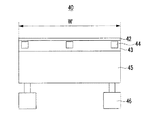
図3は、ドクターブレードユニットの平面図である。図3を参照すれば、ドクターブレードユニット40は、ドクターブレード42とグラビアロール33との間に形成される圧力を一定に維持し、ドクターブレード42の摩耗により圧力が低下する場合、ドクターブレード42をグラビアロール33側に移動させて一定の水準で圧力を調節することができるように構成される。したがって、ドクターブレード42は、図1に示されているように、グラビアロール33に対して常時一定の加圧状態を維持し、グラビアロール33で機能性膜物質の均一なブレーディングを可能とする。
FIG. 3 is a plan view of the doctor blade unit. Referring to FIG. 3, the
例えば、ドクターブレードユニット40は、ドクターブレード42の一側に取付けられる支持台43、支持台43に取付けられてドクターブレード42の応力変形(strain)を感知するストレインゲージ44、支持台43とドクターブレード42を固定させるホルダー(holder)45、およびホルダー45を移動させてグラビアロール33にドクターブレード42を加圧させるサーボモータ46をさらに含む。
For example, the
支持台43は、互いに開閉作用する上板451と下板452を有するホルダー45の上板451に取付けられた状態で固定される。ストレインゲージ44、支持台43およびドクターブレード42は柔軟性を有するため、ドクターブレード42の摩耗によって、グラビアロール33とドクターブレード42との間の圧力が弱化する。この時、ドクターブレード42は曲がった状態で広がったり曲がる方向に変形される。圧力の弱化または増加によりドクターブレード42が広がったり曲がる方向に変形されれば、ブレーディング状態、つまり、前記ドクターブレード42と前記グラビアロール33との間の応力変形が変化することがある。ドクターブレード42に従って支持台43とストレインゲージ44は変形され得る。つまり、ドクターブレード42の状態変化、つまり、応力変形はストレインゲージ44の応力変形値の変化で測定され得る。
The
ストレインゲージ44を支持台43に具備し、支持台43をドクターブレード42の一側に取付けることによって、摩耗によるドクターブレード42の交換時、使用していたストレインゲージ44を新規なドクターブレード42に移して設置する不便が除去され得る。また、支持台43は、支持台43を新規なドクターブレード42に取付ける比較的簡単な作業でストレインゲージ44を新規なドクターブレード42に設置することができるようにする。この時、新規なドクターブレード42に対するストレインゲージ44の対応状態は、廃棄されるドクターブレード42に対するストレインゲージ44の対応状態と同一になる。つまり、ストレインゲージ44は同一の状態でドクターブレード42の応力変形を感知することができるようになる。
The
一方、ドクターブレード42は、集電体21の進行方向Mに交差する方向に設定されるグラビアロール33の長さ全体範囲に対応して機能性膜物質をブレーディングすることができる十分な幅Wを有する。このようにドクターブレード42は、ホルダー45でグラビアロール33に到達する距離D(図1参照)に比べ、比較的大きな幅Wを有する。したがって、ストレインゲージ44は設定された間隔を維持して支持台43に複数が具備される。複数のストレインゲージ44は、ドクターブレード42の幅W全体範囲にわたってドクターブレード42の応力変形を感知する。また、サーモモータ46は、ドクターブレード42の幅W両側に対応するようにホルダー45の両側にそれぞれ具備され、ホルダー45を通じてドクターブレード42の前進移動を制御する。
On the other hand, the
図4は、ストレインゲージの動作原理を示す構成図である。図4を参照すれば、ストレインゲージ44の動作原理は、1個のストレインゲージ44、2個の固定抵抗Rfおよび1個の可変抵抗Rvで形成されるホイートストーンブリッジ(wheatstone bridge)回路を例に挙げて説明する。
FIG. 4 is a configuration diagram showing the operation principle of the strain gauge. Referring to FIG. 4, the operation principle of the
ストレインゲージ44は、曲がったり広がる変形に応じて抵抗値が変化する素子である。つまり、ドクターブレード42とグラビアロール33との間の圧力変化に依存し、ストレインゲージ44は支持台43を媒介としてドクターブレード42と共に曲がったり広がる。したがって、ストレインゲージ44でリアルタイムで測定される抵抗値(つまり、リアルタイムで測定されるストレインゲージ44の状態値)の変化は、リアルタイムでドクターブレード42の応力変形(つまり、リアルタイムドクターブレード42の状態が最適のブレーディング状態から離隔した程度)を分かるようになる。ストレインゲージ44と制御部47との間にOP AMPとADコンバータ(Analog to Digital Convert、ADC)が連結される。
The
つまり、最適ブレーディング状態でストレインゲージ44が変形され、これによってストレインゲージ44の抵抗値が変化され、ストレインゲージ44の抵抗値に応じてホイートストーンブリッジ回路でストレインゲージ44に分配される電圧または電流が変化される。このように微細に変化する電圧または電流をOP AMPで増幅した後、これをADコンバータ(ADC)でデジタルに変換し、リアルタイムで確認されるドクターブレード42測定応力変形値N2を制御部47に保存する。制御部47は、セッティング時、ドクターブレード42状態の初期応力変形値N1を保存している。制御部47は、ドクターブレード42の最適ブレーディング状態維持のために、初期値N1とリアルタイムで確認されるドクターブレード42の測定応力変形値N2とが同一になるようにドクターブレード42を制御する。
That is, the
図5は、ドクターブレードを制御するフローチャートである。図5を参照してドクターブレード42の応力変形(つまり、ブレーディング状態)によるドクターブレード42の制御を説明する。ドクターブレード制御は、ドクターブレード42を最適ブレーディング状態で設定する第1段階(ST1)、最適ブレーディング状態でストレインゲージ44の状態値を入力する第2段階(ST2)、およびこのストレインゲージ44の応力変形値からドクターブレード42状態の初期応力変形値N1を設定する第3段階(ST3)を含む。
FIG. 5 is a flowchart for controlling the doctor blade. With reference to FIG. 5, the control of the
ドクターブレード制御は、リアルタイムで入力されるストレインゲージ44状態値からリアルタイムでドクターブレード42応力変形値N2を確認する第4段階(ST4)、リアルタイムのドクターブレード42応力変形値N2と初期応力変形値N1とが同一であるかを判断し、N1=N2である場合、第4段階(ST4)を再び遂行する第5段階(ST5)、N1≠N2である場合、ドクターブレード42の移動距離が設定された上限値を超えたかを判断し、ドクターブレード42の移動距離が上限値を越えた場合に制御を終了する第6段階(ST6)、およびドクターブレード42の移動距離が上限値を越えていない場合にサーボモータ46を駆動してドクターブレード42を前進移動させる第7段階(ST7)を含む。
The doctor blade control is a fourth stage (ST4) for confirming the
第1段階(ST1)において、ホルダー45およびドクターブレード42の前進移動速度および移動可能距離の上限値を使用者が直接セッティングしても良い。
In the first stage (ST1), the user may directly set the forward moving speed and the upper limit value of the movable distance of the
第1段階(ST1)において、ドクターブレード42を最適ブレーディング状態でセッティングし、第2段階(ST2)においてストレインゲージ44により測定された応力変形を入力し、第3段階(ST3)においてドクターブレード42の初期応力変形値N1を設定する。初期応力変形値N1のセッティング時、固定抵抗Rfは固定された抵抗値を有し、可変抵抗Rvは別途の抵抗値で設定する。ドクターブレード42をホルダー45に設置後、グラビアロール33に接触すれば、ストレインゲージ44が変形され、この変形状態で一定の抵抗値を有するようになるが、この抵抗値を可変抵抗Rvの抵抗値で設定しても良い。そうすれば、ホイートストーンブリッジ回路の第1地点Aと第2地点Bで検出される電圧は0であり、この値をドクターブレード42応力変形の初期値N1で設定しても良い。
In the first stage (ST1), the
第4段階(ST4)において、リアルタイムで確認されるドクターブレード42応力変形値N2を、第5段階(ST5)において、初期応力変形値N1と比較しても良い。また、初期応力変形値N1を電流で設定する場合、電流の最初値を初期応力変形値N1で設定し、これをリアルタイムで確認されるドクターブレード42の応力変形値N2と互いに比較しても良い。
In the fourth stage (ST4), the
第5段階(ST5)において、制御部47はコーティング中にリアルタイムで確認されるドクターブレード42応力変形値N2を初期応力変形値N1と比較し、その差に基づいてドクターブレード42が最適ブレーディング状態から離隔した程度を判断する。例えば、制御部47は、N1≠N2である場合、ドクターブレード42が磨耗されたと判断し、第7段階(ST7)において、サーボモータ46を駆動させてホルダー45とドクターブレード42をグラビアロール33側に前進移動させる。制御部47は、第5〜第7段階(ST5〜ST7)を同時に遂行しながら、ストレインゲージ44に分配される電圧または電流によりリアルタイムで確認されるドクターブレード42応力変形値N2が初期応力変形値N1に到達するまで微細にドクターブレード42を前進移動させ、コーティング中に最適ブレーディング状態で再びセッティングする。
In the fifth stage (ST5), the
第6段階(ST6)において、制御部47はドクターブレード42の移動距離がその上限値を越えた場合(つまり、ドクターブレード42が集電体21に過度に近接した状態)、制御を終了する前に警報(alarm)を発生させても良い(ST8)。第6段階(ST6)において、ドクターブレード42が移動距離上限値に到達したことは、ホルダー45やドクターブレード42の移動経路に設置されてタッチされるリミットスイッチ48の感知信号から制御部47で判断しても良い。前記ホルダー45またはドクターブレード42はリミットスイッチ48と接触する時、前記リミットスイッチ48は制御部に信号を送り、設定された上限値に到達したことを知らせても良い。また、ドクターブレード42の移動距離上限値は、サーボモータ46回転数のエンコーダー値で分かることもできる。
In the sixth stage (ST6), when the movement distance of the
再び図3を参照すれば、第6段階(ST6)においてサーボモータ46でホルダー45が前進移動時、ドクターブレード42の右側が左側よりも磨耗されたり、左側が右側よりも磨耗される場合、3個のストレインゲージ44のそれぞれで測定される抵抗値(つまり、ドクターブレード応力変形値)が互いに異なるように示される。これによって、制御部47は2個のサーボモータ46をホルダー45の右側と左側のそれぞれでリアルタイムで互いに異なるように制御し、グラビアロール33に作用するドクターブレード42の加圧力をドクターブレード42幅W全体範囲内で均一にすることができる。つまり、制御部47は、ドクターブレード42の左側よりも右側がさらに摩耗された場合、左側よりも右側に位置するサーボモータ46をさらに前進移動させ、ドクターブレード42幅W全体範囲で均一なブレーディングを可能とする。
Referring to FIG. 3 again, in the sixth stage (ST6), when the
図6は、本発明の一実施形態による機能性膜コーティング方法のフローチャートである。図6を参照すれば、本発明の一実施形態の機能性膜コーティング方法(以下、「コーティング方法」という)は、図1のコーティング装置と図5のドクターブレード制御を含む。つまり、本発明の一実施形態のコーティング方法は、グラビアロール33の機能性物質をブレーディングするドクターブレード42の応力変形をリアルタイムで感知し、リアルタイムで感知したドクターブレード42の測定された応力変形を最適ブレーディング状態と比較し、ドクターブレード42を最適ブレーディング状態で制御する段階(図3参照)、および一方向に進行される集電体21に形成された活物質層22の厚さT1を測定し、この測定値を設定値と比較し、測定値と設定値とが一致するようにグラビアロール33の回転速度を制御する段階(図6参照)を含む。
FIG. 6 is a flowchart of a functional film coating method according to an embodiment of the present invention. Referring to FIG. 6, a functional film coating method (hereinafter referred to as “coating method”) according to an embodiment of the present invention includes the coating apparatus of FIG. 1 and the doctor blade control of FIG. That is, in the coating method according to the embodiment of the present invention, the stress deformation of the
ここでは、第1、第2厚さ測定器51、52およびクライビオロール33を中心として説明する。図5のドクターブレード制御は、図6のコーティング方法が遂行される間に共に進行される。
Here, the first and second
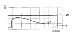
図7は、機能性膜のコーティング前後の厚さを測定する第1厚さ測定器と第2厚さ測定器の波形図であり、図8は機能性膜のコーティング前後の電極板の断面図である。図7および図8を参照すれば、第1厚さ測定器51は、機能性膜23をコーティングする前に流入される活物質層22の厚さT1を測定し、活物質層22の表面形状に対応する第1波形W1を形成する。第2厚さ測定器52は、機能性膜23をコーティングした後に活物質層22と機能性膜23との合計厚さT2を測定し、図6に示されているように活物質層22の表面形状と関係なく均一な第2波形W2を形成する。
FIG. 7 is a waveform diagram of the first thickness measuring instrument and the second thickness measuring instrument for measuring the thickness before and after coating of the functional film, and FIG. 8 is a cross-sectional view of the electrode plate before and after coating of the functional film. It is. Referring to FIGS. 7 and 8, the first
再び図6を参照すれば、本発明の一実施形態のコーティング方法は、図8に示されているように活物質層22に機能性膜23を形成した後、図7に示されているように第2厚さ測定器52で第2波形W2が出力されるように行われる。例えば、コーティング方法は、機能性膜物質を収容するグラビアロール33の微細溝の容積量を調節しても良く、グラビアロール33の回転速度および集電体21の進行速度を制御しても良く、便宜上、本実施形態で集電体21の進行速度を一定にし、グラビアロール33の回転速度を制御しても良い。集電体21の進行速度が一定な場合、グラビアロール33の回転速度を増加させれば機能性膜23のコーティング厚さ(T2−T1)は薄くなり、回転速度を減少させればコーティング厚さ(T2−T1)は厚くなる。
Referring to FIG. 6 again, in the coating method according to an embodiment of the present invention, the
本発明の一実施形態のコーティング方法は、コーティング後、活物質層22と機能性膜23で形成される合計厚さT2の設定値S2を入力し、設定値S2と活物質層22厚さT1の第1測定値M1との差(S2−M1)、および設定値S2と第2測定値M2(活物質層22と機能性膜23の合計厚さT2の測定値)との差(S2−M2)に対するグラビアロール33の回転速度変更比(ΔV)を入力する第11段階(ST11)、第1厚さ測定器51で活物質層22の厚さT1を測定し、第1測定値M1を入力する第12段階(ST12)、設定値S2と入力される第1測定値M1とを比較する第13段階(ST13)、厚さの差、つまり、設定値S2と第1測定値M1との差(S2−M1)による回転速度変更比(ΔV)を確認し、グラビアロール33の回転速度を設定する第14段階(ST14)、活物質層22が集電体21上で順序(n)が1であるかを判断する第15段階(ST15)、およびnが1である時、入力された回転速度でコーティングする第19段階(ST19)を含む。
In the coating method of one embodiment of the present invention, after coating, a set value S2 of the total thickness T2 formed by the
第19段階(ST19)は、活物質層22の前端前で設定された時間の間にさらに進行され、活物質層22の後端後で設定された時間の間にさらに進行された後に終了され、活物質層22の両端に機能性膜物質による機能性膜23の側端部L3、L4をさらに形成しても良い。側端部L3、L4は、活物質層22と無地部との境界に合計厚さT2の偏差を除去することができる。
The nineteenth stage (ST19) proceeds further during a time set before the front end of the
第13段階(ST13)で第1測定値M1が連続的に測定されると活物質層を連続的に具備した(図示せず)場合であり、第1測定値M1が一定時間毎に断絶する状態で測定されると活物質層22をパターンで形成した場合である(図8参照)。
When the first measured value M1 is continuously measured in the thirteenth stage (ST13), the active material layer is continuously provided (not shown), and the first measured value M1 is cut off at regular intervals. When measured in a state, the
本実施形態のコーティング方法は、基本的に、第1厚さ測定器51の第1波形W1を根拠として活物質層22と機能性膜23との合計厚さT2を均一に形成しても良いが、第2厚さ測定器52の第2波形W2を根拠として合計厚さT2をさらに均一に形成しても良い。この場合、第11段階(ST11)は、設定値S2と合計厚さT2の第2測定値M2との差(S2−M2)に対するグラビアロール33の回転速度変更比(ΔV)をさらに入力する。
In the coating method of this embodiment, basically, the total thickness T2 of the
コーティング方法は、第19段階(ST19)でコーティング後、nが1ではない時、例えばnが2以上である時、第2厚さ測定器52で合計厚さT2を測定し、第2測定値M2をフィードバックする第16段階(ST16)、設定値S2とフィードバックされる第2測定値M2とを比較する第17段階(ST17)、厚さの差、つまり、設定値S2と第2測定値M2との差(S2−M2)による回転速度変更比(ΔV)を確認し、グラビアロール33の回転速度を第14段階(ST14)で設定された回転速度に変更する第18段階(ST18)、およびこの状態でコーティングする第19段階(ST19)を含む。また。第16段階(ST16)〜第19段階(ST19)は、第2厚さ測定器52により以前の工程でコーティングされた機能性膜23の厚さを活物質層22の厚さと共に測定して、後続する工程で厚さ合計T2をより均一にすることができる。言い換えれば、前記第2厚さ測定器52は、前記機能性膜23/活物質層22構造のうちの一つの合計厚さT2を測定して、前記全体的な合計厚さT2が設定値S2から外れるかどうかを判断することができる。先に形成された機能性膜23/活物質層22構造の全体的な合計厚さT2が設定値S2から外れる場合、前記グラビアロール33の回転速度が調整されて、後続形成される機能性膜23/活物質層22構造の全体的な合計厚さT2が前記設定値S2と同一になる。
In the coating method, after coating in the nineteenth stage (ST19), when n is not 1, for example, when n is 2 or more, the total thickness T2 is measured by the second
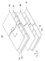
図9は、本発明の一実施形態による2次電池において、電極組立体の分解斜視図であり、図10は図9のX−X線に沿って切断した断面図である。図9および図10を参照すれば、電極組立体200を中心として本発明の一実施形態の2次電池を説明する。電極組立体200を内蔵するケースおよび電極組立体200に電気的に連結されるキャップ組立体は、公知の技術を適用することができるため、これらに対する説明は省略する。
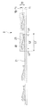
FIG. 9 is an exploded perspective view of an electrode assembly in a secondary battery according to an embodiment of the present invention, and FIG. 10 is a cross-sectional view taken along line XX of FIG. Referring to FIGS. 9 and 10, a secondary battery according to an embodiment of the present invention will be described with an
電極組立体200は、正極と負極を選択的に形成する第1電極板102と第2電極板202およびこれらの間に配置される分離膜302を含み、第1、第2電極板102、202の間に分離膜302を配置してワインディングすることにより形成される。第1電極板102は、第1集電体121に第1活物質層122と第1機能性膜123を備える。第2電極板202は、第2集電体221に第2活物質層222と第2機能性膜223を備える。ワインディング状態で、第2活物質層222と第2機能性膜223の積層構造は分離膜302を間において第1活物質層122と第1機能性膜123の積層構造に互いに対向する。
The
第1、第2電極板102、202は同一の構造を形成するため、第1電極板102を基準として説明する。第1電極板102で第1活物質層122は第1集電体121の長さ方向(x軸方向)に不規則な厚さT1を有し、前記第1活物質層122と共に第1機能性膜123は厚さT1の偏差にも拘わらず均一な合計厚さT2を有する。つまり、合計厚さT2は設定値S2に一致する。
Since the first and
また、第1機能性膜123は、第1活物質層122の長さL2よりも長くL1形成され、第1活物質層122の両端に機能性膜物質で形成される第1機能性膜123の側端部L3、L4をさらに形成する。側端部L3、L4が第1活物質層122と無地部との境界に合計厚さT2の偏差を除去するため、セル形状が不均一になることを防止することができる。特に、前記側端部L3、L4はワインディング時、電極組立体200に不均一な圧力が加わることを防止でき、従って、不均一な形状と不均一な圧力によって電解液の含浸が行われないことを防止することができる。
In addition, the first
以上で本発明の好適な実施形態について説明したが、本発明はこれに限定されるのではなく、特許請求の範囲と発明の詳細な説明および添付図面の範囲内で多様に変形して実施することが可能であり、これも本発明の範囲に属することは当然である。 The preferred embodiments of the present invention have been described above, but the present invention is not limited to these embodiments, and various modifications can be made within the scope of the claims, the detailed description of the invention, and the accompanying drawings. Of course, this is also within the scope of the present invention.
2 電極板
102、202 第1、第2電極板
21 集電体
121、221 第1、第2集電体
22 活物質層
122、222 第1、第2活物質層
23 機能性膜
123、223 第1、第2機能性膜
200 電極組立体
302 分離膜
31、32 第1、第2ロール
33 グラビアロール
G 微細溝
34 ダム(dam)
40 ドクターブレードユニット
42 ドクターブレード
W ドクターブレード幅
43 支持台
44 ストレインゲージ
45 ホルダー(holder)
451、452 上下板
46 サーボモータ
47 制御部
48 リミットスイッチ
51、52 第1、第2厚さ測定器
L1 機能性膜の長さ
L2 活物質層の長さ
L3、L4 側端部
M 集電体の進行方向
M1、M2 第1、第2測定値
N1 ドクターブレード状態の初期応力変形値
N2 リアルタイムで確認されるドクターブレード測定応力変形値
Rf 固定抵抗
Rv 可変抵抗
S2 合計厚さの設定値
T1 活物質層厚さ
T2 活物質層と機能性膜との合計厚さ
ΔV 回転速度変更比
2
40
451, 452 Upper and
Claims (19)
前記集電体を進行させる第1ロールと第2ロール;
前記機能性膜を前記活物質層にコーティングするように構成されたグラビアロール;
前記活物質層と機能性膜との合計厚さと前記活物質層の厚さのうちの少なくとも一つを測定するように構成された厚さ測定器;および
前記厚さ測定器と連結され、前記グラビアロールの回転速度を制御するように構成された制御部;
を含む、機能性膜コーティング装置。 In an apparatus for coating a current collector on which an active material layer is formed with a functional film,
A first roll and a second roll for advancing the current collector;
A gravure roll configured to coat the functional film on the active material layer;
A thickness measuring device configured to measure at least one of a total thickness of the active material layer and the functional film and a thickness of the active material layer; and connected to the thickness measuring device, A controller configured to control the rotational speed of the gravure roll;
A functional film coating apparatus.
第1ロールと第2ロールに沿って前記活物質層が形成された集電体を進行させ、
グラビアロールを利用して前記機能性膜を前記活物質層にコーティングし、
前記活物質層と機能性膜との合計厚さが前記機能性膜の長さに沿って均一であるように前記グラビアロールの回転速度を制御する段階を含む、機能性膜コーティング方法。 In the method of coating a functional film on a current collector formed with an active material layer,
Advancing the current collector formed with the active material layer along the first roll and the second roll,
Coating the functional film on the active material layer using a gravure roll,
A functional film coating method comprising the step of controlling a rotation speed of the gravure roll so that a total thickness of the active material layer and the functional film is uniform along a length of the functional film.
測定器で前記活物質層の厚さを測定し、
前記活物質層の厚さと設定された厚さとを比較し、
前記機能性膜と活物質層との合計厚さが設定された厚さと同一であるように前記活物質層に機能性膜を形成する過程を含む、請求項5に記載の機能性膜コーティング方法。 Coating the functional film comprises:
Measure the thickness of the active material layer with a measuring instrument,
Compare the thickness of the active material layer with the set thickness,
The functional film coating method according to claim 5, comprising a step of forming a functional film on the active material layer so that a total thickness of the functional film and the active material layer is the same as a set thickness. .
前記測定器で前記活物質層と前記機能性膜との合計厚さを測定し、
前記合計厚さと設定された厚さとを比較し、
前記合計厚さと前記設定された厚さとの差に基づいて前記グラビアロールの回転速度を制御する過程を含む、請求項5に記載の機能性膜コーティング方法。 Controlling the rotational speed comprises:
Measure the total thickness of the active material layer and the functional film with the measuring device,
Compare the total thickness with the set thickness,
The functional film coating method according to claim 5, comprising a step of controlling a rotation speed of the gravure roll based on a difference between the total thickness and the set thickness.
前記合計厚さと前記設定された厚さとの差に基づいて前記グラビアロールの回転速度を制御する段階は、
活物質層と機能性膜との合計厚さを制御する過程を含み、
前記グラビアロールの下流で前記測定器による前記合計厚さの測定に基づいて前記測定器の上流(up stream)で行われる、請求項7に記載の機能性膜コーティング方法。 The step of measuring the total thickness of the active material layer and the functional film is performed downstream of the gravure roll,
Controlling the rotational speed of the gravure roll based on the difference between the total thickness and the set thickness,
Including the process of controlling the total thickness of the active material layer and the functional film,
The functional film coating method according to claim 7, wherein the functional film coating method is performed upstream of the measuring device based on the measurement of the total thickness by the measuring device downstream of the gravure roll.
前記機能性膜を前記活物質層にコーティングするように構成されたグラビアロール;
余剰分の機能性膜物質を前記グラビアロールからかき出すドクターブレードと、前記ドクターブレードの応力変形を測定するように構成された少なくとも一つのストレインゲージとを含むドクターブレードユニット;および
前記少なくとも一つのストレインゲージと連結されて前記ドクターブレードユニットの位置を制御するように構成された制御部;
を含む、機能性膜コーティング装置。 In an apparatus for coating a current collector on which an active material layer is formed with a functional film,
A gravure roll configured to coat the functional film on the active material layer;
A doctor blade unit comprising: a doctor blade for scraping excess functional membrane material from the gravure roll; and at least one strain gauge configured to measure stress deformation of the doctor blade; and the at least one strain gauge And a controller configured to control the position of the doctor blade unit connected to the controller;
A functional film coating apparatus.
前記ドクターブレードと前記少なくとも一つのストレインゲージとの間に位置する支持台、
前記支持台と前記ドクターブレードを固定するホルダー、および
前記制御部により制御され、前記ホルダーを前記グラビアロールに対して動かして前記ドクターブレードと前記グラビアロールとの間の圧力を変更するように構成された少なくとも一つのサーボモータを含む、請求項10に記載の機能性膜コーティング装置。 The doctor blade unit is
A support base positioned between the doctor blade and the at least one strain gauge;
A holder for fixing the support base and the doctor blade, and controlled by the control unit, and configured to change the pressure between the doctor blade and the gravure roll by moving the holder relative to the gravure roll. The functional film coating apparatus according to claim 10, further comprising at least one servo motor.
ドクターブレードで測定された応力変形を感知し、
前記ドクターブレードの応力変形の最適値と前記測定された応力変形とを比較し、
前記測定された応力変形を感知する段階と、前記応力変形の最適値と前記測定された応力変形とを比較する段階とに基づいて最適のブレーディング状態で前記ドクターブレードを維持することによって、前記グラビアロールから余剰分の機能性膜物質を除去し、
前記活物質層が形成された前記集電体を進行させ、
前記機能性膜と前記活物質層との合計厚さが前記機能性膜の長さに沿って均一であるように前記グラビアロールで前記活物質層に前記機能性膜をコーティングさせる段階を含む、機能性膜コーティング方法。 In the method of coating a functional film on a current collector formed with an active material layer,
Senses stress deformation measured with a doctor blade,
Comparing the optimum stress deformation of the doctor blade with the measured stress deformation;
Maintaining the doctor blade in an optimal braiding state based on sensing the measured stress deformation and comparing the optimal value of the stress deformation with the measured stress deformation; Remove excess functional film material from the gravure roll,
Advancing the current collector on which the active material layer is formed;
Coating the active material layer with the gravure roll so that the total thickness of the functional film and the active material layer is uniform along the length of the functional film, Functional film coating method.
前記測定された応力変形と前記応力変形の最適値との差に基づいて少なくとも一つのサーボモータを利用して前記グラビアロールに対して前記ドクターブレードを動かすことによって、前記ドクターブレードと前記グラビアロールとの間の圧力を変更する段階を含む、請求項13に記載の機能性膜コーティング方法。 Maintaining the doctor blade in the optimal braiding condition comprises:
By moving the doctor blade relative to the gravure roll using at least one servo motor based on the difference between the measured stress deformation and the optimum value of the stress deformation, the doctor blade and the gravure roll 14. The method of coating a functional film according to claim 13, comprising the step of changing the pressure between the two.
少なくとも一つのストレインゲージで前記測定された応力変形を感知する段階を含む、請求項13に記載の機能性膜コーティング方法。 Maintaining the doctor blade in the optimal braiding condition comprises:
The functional film coating method according to claim 13, comprising sensing the measured stress deformation with at least one strain gauge.
前記支持台は前記ストレインゲージと前記ドクターブレードとの間に位置する、請求項15に記載の機能性膜コーティング方法。 The at least one strain gauge is located on a support;
The functional film coating method according to claim 15, wherein the support base is located between the strain gauge and the doctor blade.
前記サーボモータは前記ドクターブレードと前記グラビアロールとの間の圧力を変更するために、前記ホルダーを前記グラビアホールに対して動かす、請求項16に記載の機能性膜コーティング方法。 The support base and the doctor blade are fixed by a holder,
The functional film coating method according to claim 16, wherein the servo motor moves the holder with respect to the gravure hole in order to change a pressure between the doctor blade and the gravure roll.
前記グラビアロールに対して前記最適のブレーディング状態で前記ドクターブレードをセッティングし、
前記ドクターブレードが前記最適のブレーディング状態にある間、ストレインゲージで前記応力変形の最適値を測定し、
制御部に前記応力変形の最適値を入力し、
前記ストレインゲージで前記ドクターブレードで測定された応力変形を持続的に測定し、
前記測定された応力変形を前記応力変形の最適値と比較し、
前記測定された応力変形が前記応力変形の最適値と同一でない場合、前記グラビアロールに対して前記ドクターブレードを動かすことによって、前記ドクターブレードと前記グラビアロールとの間の圧力を最適化する段階を含む、請求項13に記載の機能性膜コーティング方法。 Maintaining the doctor blade in the optimal braiding condition comprises:
Setting the doctor blade in the optimal braiding state for the gravure roll,
While the doctor blade is in the optimal braiding state, measure the optimum value of the stress deformation with a strain gauge,
Enter the optimal value of stress deformation into the control unit,
Continuously measure the stress deformation measured by the doctor blade with the strain gauge,
Comparing the measured stress deformation with the optimum value of the stress deformation;
Optimizing the pressure between the doctor blade and the gravure roll by moving the doctor blade relative to the gravure roll if the measured stress deformation is not the same as the optimum value of the stress deformation; The functional film coating method according to claim 13, further comprising:
前記ドクターブレードが前記グラビアロールに対して動いた距離が予め設定された上限距離よりも大きい場合に警報を鳴らすことをさらに含む、請求項18に記載の機能性膜コーティング方法。 Maintaining the doctor blade in the optimal braiding condition comprises:
The functional film coating method according to claim 18, further comprising sounding an alarm when a distance that the doctor blade moves with respect to the gravure roll is larger than a preset upper limit distance.
Applications Claiming Priority (4)
| Application Number | Priority Date | Filing Date | Title |
|---|---|---|---|
| US28240910P | 2010-02-04 | 2010-02-04 | |
| US61/282,409 | 2010-02-04 | ||
| US12/923,506 | 2010-09-24 | ||
| US12/923,506 US20110189378A1 (en) | 2010-02-04 | 2010-09-24 | Apparatus and method for coating a functional layer |
Publications (2)
| Publication Number | Publication Date |
|---|---|
| JP2011165663A true JP2011165663A (en) | 2011-08-25 |
| JP5517358B2 JP5517358B2 (en) | 2014-06-11 |
Family
ID=44053051
Family Applications (1)
| Application Number | Title | Priority Date | Filing Date |
|---|---|---|---|
| JP2011016271A Active JP5517358B2 (en) | 2010-02-04 | 2011-01-28 | Functional film coating apparatus and coating method |
Country Status (5)
| Country | Link |
|---|---|
| US (2) | US20110189378A1 (en) |
| EP (1) | EP2355224B1 (en) |
| JP (1) | JP5517358B2 (en) |
| KR (1) | KR101256068B1 (en) |
| CN (1) | CN102145327B (en) |
Cited By (7)
| Publication number | Priority date | Publication date | Assignee | Title |
|---|---|---|---|---|
| JP2014182992A (en) * | 2013-03-21 | 2014-09-29 | Toyota Industries Corp | Electrode manufacturing method and electrode manufacturing device |
| JP2015231620A (en) * | 2014-05-27 | 2015-12-24 | パロ アルト リサーチ センター インコーポレイテッド | Method and system for creating aerosol |
| JP2017212097A (en) * | 2016-05-25 | 2017-11-30 | 日本電気株式会社 | Electrode manufacturing method and electrode inspection method |
| JP2018020287A (en) * | 2016-08-03 | 2018-02-08 | 凸版印刷株式会社 | Coating apparatus and ink coating method |
| JP2018181781A (en) * | 2017-04-21 | 2018-11-15 | トヨタ自動車株式会社 | Electrode plate manufacturing device |
| WO2020195055A1 (en) * | 2019-03-27 | 2020-10-01 | パナソニックIpマネジメント株式会社 | Secondary battery |
| JP7471113B2 (en) | 2020-03-10 | 2024-04-19 | 住友化学株式会社 | Manufacturing method and management method of laminate |
Families Citing this family (24)
| Publication number | Priority date | Publication date | Assignee | Title |
|---|---|---|---|---|
| US20110189378A1 (en) | 2010-02-04 | 2011-08-04 | Moon So-Ii | Apparatus and method for coating a functional layer |
| US9561522B2 (en) * | 2011-03-28 | 2017-02-07 | Helmut Knorr | Ultrasonic transmitting and receiving device for thickness and/or grammage measurement |
| DE102012201378B4 (en) * | 2012-01-31 | 2015-10-08 | Koenig & Bauer Ag | Method for using a device for setting a doctor blade on a lateral surface of a rotatable roller |
| CN102921604B (en) * | 2012-11-14 | 2015-07-08 | 深圳市信宇人科技有限公司 | Flexible scraper and micro-gravure coating head |
| WO2014176590A1 (en) * | 2013-04-26 | 2014-10-30 | Kadant Inc. | Systems and methods for doctor blade load and vibration measurement as well as blade vibration mitigation |
| DE102013007602A1 (en) * | 2013-05-03 | 2014-11-06 | Schattdecor Ag | Process for producing a printable single-layer or multilayer material web and a material web produced thereon and an associated system for producing such a material web |
| CN103521389B (en) * | 2013-09-30 | 2015-11-18 | 天津市永昌焊丝有限公司 | A kind of flux-cored wire oiling device |
| DE102013225691B4 (en) * | 2013-12-12 | 2017-11-16 | Koenig & Bauer Ag | A system for feeding and metering ink into an inking unit of a printing machine and method for renewing a metering edge effective for color metering |
| JP6371527B2 (en) * | 2014-01-07 | 2018-08-08 | 富士機械工業株式会社 | Coating equipment |
| CN104324859B (en) * | 2014-06-27 | 2017-07-28 | 中航锂电(江苏)有限公司 | A kind of battery diaphragm coats the method and apparatus of scraping |
| KR101689645B1 (en) * | 2015-06-19 | 2016-12-26 | (주)피엔티 | Apparatus for coating edge of electrode layer web with electrode layer |
| US9925555B2 (en) * | 2016-02-08 | 2018-03-27 | Valmet Technologies, Inc. | Folded sealing blade for a coating applicator |
| CN106269388B (en) * | 2016-08-19 | 2019-08-20 | 南通皋鑫电子股份有限公司 | High-voltage diode inside courtyard apparatus for coating |
| KR102039704B1 (en) * | 2019-06-14 | 2019-12-03 | 김상윤 | Apparatus and method for manufacturing a filter of visible light transmitting multilayer structure for blocking fine dusts |
| KR102072945B1 (en) * | 2019-07-29 | 2020-02-04 | 주식회사 명배메탈 | Film coating device using nontoxic coating liquid |
| CN111013920A (en) * | 2019-12-22 | 2020-04-17 | 安徽本色印刷有限公司 | Wine box packing printing is with brush mucilage binding and is put |
| KR102657146B1 (en) | 2020-04-07 | 2024-04-11 | 주식회사 엘지화학 | Gravure coater testing apparatus and gravure coater |
| JP7261783B2 (en) | 2020-11-18 | 2023-04-20 | プライムプラネットエナジー&ソリューションズ株式会社 | Electrode manufacturing method and electrode paste coating device |
| CN113275209B (en) * | 2021-07-21 | 2021-09-28 | 浙江双元科技股份有限公司 | Lithium battery pole piece coating thickness detection device, system and method |
| CN113910673A (en) * | 2021-10-13 | 2022-01-11 | 浙江中包派克包装有限公司 | Automatic case equipment that sticks with paste of overlength type |
| CN114308519A (en) * | 2021-12-22 | 2022-04-12 | 山东膜丽东方新材料科技有限公司 | Reverse coating structure of coating machine |
| CN114824505B (en) * | 2022-04-06 | 2023-11-03 | 苏州时代华景新能源有限公司 | A zero-deformation manufacturing process for rolled batteries and its production line system |
| CN217774594U (en) * | 2022-05-05 | 2022-11-11 | 宁德时代新能源科技股份有限公司 | Coating system |
| WO2026024052A1 (en) * | 2024-07-23 | 2026-01-29 | 주식회사 엘지에너지솔루션 | Coating device and method of manufacturing separator using same |
Citations (12)
| Publication number | Priority date | Publication date | Assignee | Title |
|---|---|---|---|---|
| JPH01118403A (en) * | 1987-10-30 | 1989-05-10 | Toyota Motor Corp | Manufacture of green sheet and its device |
| JPH02106809A (en) * | 1988-10-13 | 1990-04-18 | Fujitsu Ltd | Ceramics substrate green sheet molding device |
| JPH03123670A (en) * | 1989-10-06 | 1991-05-27 | Toray Ind Inc | Preparation of resin-supported release sheet |
| JPH05115832A (en) * | 1991-10-30 | 1993-05-14 | Kawasaki Steel Corp | Control method for continuous insulating coating of thin metal strip |
| JPH06129978A (en) * | 1992-10-19 | 1994-05-13 | New Oji Paper Co Ltd | Film quality inspection method and device |
| JPH07289982A (en) * | 1994-04-28 | 1995-11-07 | Sekisui Chem Co Ltd | Method of controlling coating thickness of coating agent |
| JPH11101615A (en) * | 1997-09-25 | 1999-04-13 | Murata Mfg Co Ltd | Film thickness control device in sheet forming machine |
| JP2001266943A (en) * | 2000-03-17 | 2001-09-28 | Sony Corp | Battery manufacturing method and coating device used therefor |
| JP2003145705A (en) * | 2001-11-15 | 2003-05-21 | Dainippon Printing Co Ltd | Doctor device |
| JP2007253108A (en) * | 2006-03-24 | 2007-10-04 | Matsushita Electric Ind Co Ltd | Gravure coating equipment |
| JP2009028719A (en) * | 2007-07-05 | 2009-02-12 | Toyota Motor Corp | Coating device |
| JP2009193906A (en) * | 2008-02-18 | 2009-08-27 | Panasonic Corp | Application weight measuring method, manufacturing method and manufacturing apparatus for heat-resistant layer of battery electrode plate |
Family Cites Families (21)
| Publication number | Priority date | Publication date | Assignee | Title |
|---|---|---|---|---|
| CH530233A (en) * | 1970-03-26 | 1972-04-14 | Triatex Internat Ag Fuer Texti | Process for the finishing of cellulosic textile goods |
| DE2913421C3 (en) * | 1979-04-04 | 1982-04-29 | J.M. Voith Gmbh, 7920 Heidenheim | Method and device for stripping off excess coating material from a moving web |
| JPH027663Y2 (en) * | 1985-09-06 | 1990-02-23 | ||
| JPH0671849A (en) | 1992-08-28 | 1994-03-15 | Murata Mfg Co Ltd | Screen printing method |
| WO1996006430A1 (en) * | 1994-08-22 | 1996-02-29 | Minnesota Mining And Manufacturing Company | Differential-speed gravure coating of magnetizable layers in the manufacture of magnetic recording media |
| US5783042A (en) * | 1995-12-06 | 1998-07-21 | Thermo Web Systems, Inc. | System and method of measuring deflected doctor blade angle and loading force |
| DE19627456A1 (en) * | 1996-07-08 | 1998-01-15 | Voith Sulzer Papiermasch Gmbh | Coater for use in web products, especially paper or paper board |
| DE19734262A1 (en) * | 1997-08-07 | 1999-02-11 | Voith Sulzer Papiermasch Gmbh | Process for the direct or indirect application of a liquid or pasty medium to a running material web, in particular made of paper or cardboard |
| DE19755411A1 (en) * | 1997-12-12 | 1999-06-17 | Voith Sulzer Papiertech Patent | Doctor device |
| IT1299644B1 (en) * | 1998-02-05 | 2000-03-24 | Uteco Spa Roto Flexo & Convert | MACHINE FOR ROTOCALCO PRINTING AND FOR PAINTING UP TO EIGHT COLORS |
| FI4290U1 (en) * | 1999-09-14 | 2000-01-19 | Valmet Corp | Paper machine scraper |
| KR100603268B1 (en) * | 1999-11-15 | 2006-07-20 | 삼성에스디아이 주식회사 | Current collector carbon coating device for lithium secondary battery |
| HUP0101103A2 (en) * | 2000-03-17 | 2001-11-28 | Sony Corporation | Method and equipment for manufacturing thereof dry reserve accumulators |
| JP2003145703A (en) | 2001-11-16 | 2003-05-21 | Ks Shokai:Kk | Transparent substrate material |
| JP2005034733A (en) | 2003-07-14 | 2005-02-10 | Tomoegawa Paper Co Ltd | Gravure coating apparatus and gravure coating method |
| JP4172641B2 (en) * | 2003-09-01 | 2008-10-29 | 日東電工株式会社 | Coating method and coating apparatus used therefor |
| JP4772465B2 (en) * | 2004-11-26 | 2011-09-14 | パナソニック株式会社 | Thin film intermittent coating method |
| JP2008166113A (en) * | 2006-12-28 | 2008-07-17 | Matsushita Electric Ind Co Ltd | Battery electrode manufacturing method and battery electrode manufacturing apparatus |
| JP5169395B2 (en) * | 2008-04-07 | 2013-03-27 | トヨタ自動車株式会社 | Coating apparatus and coating method |
| JP2009262070A (en) * | 2008-04-25 | 2009-11-12 | Panasonic Corp | Coating film forming apparatus, coating film forming method, polar plate for cell, and nonaqueous electrolyte secondary cell |
| US20110189378A1 (en) | 2010-02-04 | 2011-08-04 | Moon So-Ii | Apparatus and method for coating a functional layer |
-
2010
- 2010-09-24 US US12/923,506 patent/US20110189378A1/en not_active Abandoned
-
2011
- 2011-01-28 JP JP2011016271A patent/JP5517358B2/en active Active
- 2011-01-30 CN CN201110034897.6A patent/CN102145327B/en active Active
- 2011-01-31 EP EP11152716.4A patent/EP2355224B1/en active Active
- 2011-01-31 KR KR1020110009553A patent/KR101256068B1/en active Active
-
2012
- 2012-09-14 US US13/617,068 patent/US9088043B2/en active Active
Patent Citations (12)
| Publication number | Priority date | Publication date | Assignee | Title |
|---|---|---|---|---|
| JPH01118403A (en) * | 1987-10-30 | 1989-05-10 | Toyota Motor Corp | Manufacture of green sheet and its device |
| JPH02106809A (en) * | 1988-10-13 | 1990-04-18 | Fujitsu Ltd | Ceramics substrate green sheet molding device |
| JPH03123670A (en) * | 1989-10-06 | 1991-05-27 | Toray Ind Inc | Preparation of resin-supported release sheet |
| JPH05115832A (en) * | 1991-10-30 | 1993-05-14 | Kawasaki Steel Corp | Control method for continuous insulating coating of thin metal strip |
| JPH06129978A (en) * | 1992-10-19 | 1994-05-13 | New Oji Paper Co Ltd | Film quality inspection method and device |
| JPH07289982A (en) * | 1994-04-28 | 1995-11-07 | Sekisui Chem Co Ltd | Method of controlling coating thickness of coating agent |
| JPH11101615A (en) * | 1997-09-25 | 1999-04-13 | Murata Mfg Co Ltd | Film thickness control device in sheet forming machine |
| JP2001266943A (en) * | 2000-03-17 | 2001-09-28 | Sony Corp | Battery manufacturing method and coating device used therefor |
| JP2003145705A (en) * | 2001-11-15 | 2003-05-21 | Dainippon Printing Co Ltd | Doctor device |
| JP2007253108A (en) * | 2006-03-24 | 2007-10-04 | Matsushita Electric Ind Co Ltd | Gravure coating equipment |
| JP2009028719A (en) * | 2007-07-05 | 2009-02-12 | Toyota Motor Corp | Coating device |
| JP2009193906A (en) * | 2008-02-18 | 2009-08-27 | Panasonic Corp | Application weight measuring method, manufacturing method and manufacturing apparatus for heat-resistant layer of battery electrode plate |
Cited By (10)
| Publication number | Priority date | Publication date | Assignee | Title |
|---|---|---|---|---|
| JP2014182992A (en) * | 2013-03-21 | 2014-09-29 | Toyota Industries Corp | Electrode manufacturing method and electrode manufacturing device |
| JP2015231620A (en) * | 2014-05-27 | 2015-12-24 | パロ アルト リサーチ センター インコーポレイテッド | Method and system for creating aerosol |
| JP2017212097A (en) * | 2016-05-25 | 2017-11-30 | 日本電気株式会社 | Electrode manufacturing method and electrode inspection method |
| JP2018020287A (en) * | 2016-08-03 | 2018-02-08 | 凸版印刷株式会社 | Coating apparatus and ink coating method |
| JP2018181781A (en) * | 2017-04-21 | 2018-11-15 | トヨタ自動車株式会社 | Electrode plate manufacturing device |
| WO2020195055A1 (en) * | 2019-03-27 | 2020-10-01 | パナソニックIpマネジメント株式会社 | Secondary battery |
| JPWO2020195055A1 (en) * | 2019-03-27 | 2020-10-01 | ||
| JP7394327B2 (en) | 2019-03-27 | 2023-12-08 | パナソニックIpマネジメント株式会社 | secondary battery |
| US12683146B2 (en) | 2019-03-27 | 2026-07-14 | Panasonic Intellectual Property Management Co., Ltd. | Secondary battery |
| JP7471113B2 (en) | 2020-03-10 | 2024-04-19 | 住友化学株式会社 | Manufacturing method and management method of laminate |
Also Published As
| Publication number | Publication date |
|---|---|
| EP2355224B1 (en) | 2013-07-31 |
| KR20110090807A (en) | 2011-08-10 |
| US9088043B2 (en) | 2015-07-21 |
| KR101256068B1 (en) | 2013-04-18 |
| EP2355224A1 (en) | 2011-08-10 |
| CN102145327A (en) | 2011-08-10 |
| US20110189378A1 (en) | 2011-08-04 |
| JP5517358B2 (en) | 2014-06-11 |
| US20130017319A1 (en) | 2013-01-17 |
| CN102145327B (en) | 2014-01-29 |
Similar Documents
| Publication | Publication Date | Title |
|---|---|---|
| JP5517358B2 (en) | Functional film coating apparatus and coating method | |
| JP6524307B2 (en) | Method of manufacturing separator | |
| KR101241337B1 (en) | Flexible Electrode based on PDMS using Parylene Coating Layer and Fabrication Method thereof | |
| JP2004275810A (en) | Coating die using shim plate and coating method using the same | |
| KR20220061188A (en) | battery electrode with sensor | |
| WO2015198185A1 (en) | Electrochemical coating stress sensor, apparatus and method for accurately monitoring and controlling electrochemical reactions and material coating | |
| CN112097946B (en) | Integrated flexible temperature and pressure sensor, method for making same, and system for non-planar temperature measurement | |
| KR101201124B1 (en) | Method of coating electrode materials for secondary battery | |
| JP2009150738A (en) | Sensor and detection device | |
| US9935330B2 (en) | Battery manufacturing method and battery manufacturing apparatus | |
| US20150382477A1 (en) | Burning method | |
| JP3960040B2 (en) | Sheet forming device | |
| KR20240090090A (en) | Electrode manufacturing apparatus and method | |
| JP2016140832A (en) | CONTINUOUS COATING APPARATUS AND METHOD FOR PRODUCING A COATED SUBSTRATE | |
| KR101664110B1 (en) | Apparatus of treating bared wafer | |
| JP5510222B2 (en) | Electronic component manufacturing apparatus and manufacturing method thereof | |
| JP7521209B2 (en) | Continuous coating device and method for manufacturing gas diffusion electrode using the same | |
| CN118125373B (en) | Preparation method of hydrogen sensor and hydrogen sensor | |
| KR20260002878A (en) | Method and device for manufacturing electrodes of battery cells | |
| KR102417516B1 (en) | Method for manufacturing sensing apparatus, and apparatus thereof | |
| JP2018081769A (en) | Electrode inspection method and electrode inspection device | |
| JP5150071B2 (en) | Manufacturing method of heating head | |
| FI121753B (en) | Method for setting scraper support bar and scraper position | |
| CN121079197A (en) | Press and method for producing a multilayer product | |
| CN121375271A (en) | Methods for compensating the roller surface height of thermal laminating rollers |
Legal Events
| Date | Code | Title | Description |
|---|---|---|---|
| A977 | Report on retrieval |
Free format text: JAPANESE INTERMEDIATE CODE: A971007 Effective date: 20130115 |
|
| A131 | Notification of reasons for refusal |
Free format text: JAPANESE INTERMEDIATE CODE: A131 Effective date: 20130122 |
|
| A521 | Request for written amendment filed |
Free format text: JAPANESE INTERMEDIATE CODE: A523 Effective date: 20130419 |
|
| A131 | Notification of reasons for refusal |
Free format text: JAPANESE INTERMEDIATE CODE: A131 Effective date: 20130514 |
|
| A521 | Request for written amendment filed |
Free format text: JAPANESE INTERMEDIATE CODE: A523 Effective date: 20130812 |
|
| A02 | Decision of refusal |
Free format text: JAPANESE INTERMEDIATE CODE: A02 Effective date: 20130910 |
|
| A521 | Request for written amendment filed |
Free format text: JAPANESE INTERMEDIATE CODE: A523 Effective date: 20140109 |
|
| A911 | Transfer to examiner for re-examination before appeal (zenchi) |
Free format text: JAPANESE INTERMEDIATE CODE: A911 Effective date: 20140124 |
|
| TRDD | Decision of grant or rejection written | ||
| A01 | Written decision to grant a patent or to grant a registration (utility model) |
Free format text: JAPANESE INTERMEDIATE CODE: A01 Effective date: 20140304 |
|
| A61 | First payment of annual fees (during grant procedure) |
Free format text: JAPANESE INTERMEDIATE CODE: A61 Effective date: 20140331 |
|
| R150 | Certificate of patent or registration of utility model |
Ref document number: 5517358 Country of ref document: JP Free format text: JAPANESE INTERMEDIATE CODE: R150 |
|
| R250 | Receipt of annual fees |
Free format text: JAPANESE INTERMEDIATE CODE: R250 |
|
| R250 | Receipt of annual fees |
Free format text: JAPANESE INTERMEDIATE CODE: R250 |
|
| R250 | Receipt of annual fees |
Free format text: JAPANESE INTERMEDIATE CODE: R250 |
|
| R250 | Receipt of annual fees |
Free format text: JAPANESE INTERMEDIATE CODE: R250 |
|
| R250 | Receipt of annual fees |
Free format text: JAPANESE INTERMEDIATE CODE: R250 |
|
| R250 | Receipt of annual fees |
Free format text: JAPANESE INTERMEDIATE CODE: R250 |
|
| R250 | Receipt of annual fees |
Free format text: JAPANESE INTERMEDIATE CODE: R250 |
|
| R250 | Receipt of annual fees |
Free format text: JAPANESE INTERMEDIATE CODE: R250 |
|
| R250 | Receipt of annual fees |
Free format text: JAPANESE INTERMEDIATE CODE: R250 |
|
| R250 | Receipt of annual fees |
Free format text: JAPANESE INTERMEDIATE CODE: R250 |