JP2011171237A - Luminaire - Google Patents
Luminaire Download PDFInfo
- Publication number
- JP2011171237A JP2011171237A JP2010036056A JP2010036056A JP2011171237A JP 2011171237 A JP2011171237 A JP 2011171237A JP 2010036056 A JP2010036056 A JP 2010036056A JP 2010036056 A JP2010036056 A JP 2010036056A JP 2011171237 A JP2011171237 A JP 2011171237A
- Authority
- JP
- Japan
- Prior art keywords
- lighting fixture
- housing
- heat
- lighting
- light source
- Prior art date
- Legal status (The legal status is an assumption and is not a legal conclusion. Google has not performed a legal analysis and makes no representation as to the accuracy of the status listed.)
- Withdrawn
Links
Images


Landscapes
- Led Device Packages (AREA)
- Fastening Of Light Sources Or Lamp Holders (AREA)
- Arrangement Of Elements, Cooling, Sealing, Or The Like Of Lighting Devices (AREA)
- Non-Portable Lighting Devices Or Systems Thereof (AREA)
Abstract
【課題】放熱性を向上し、信頼性の高い照明器具を提供する。
【解決手段】この照明器具は、筐体1と、筐体1に収容される光源(LEDパッケージ5)と、を有する照明器具であって、光源が実装される実装基板51と筐体1とが熱的に接続されており、筐体1の外周面の少なくとも一部が熱放射性部材2b、7bで覆われている。
【選択図】図2An object of the present invention is to provide a lighting device with improved heat dissipation and high reliability.
The lighting apparatus includes a housing 1 and a light source (LED package 5) accommodated in the housing 1, and includes a mounting substrate 51 on which the light source is mounted, and the housing 1. Are thermally connected, and at least a part of the outer peripheral surface of the housing 1 is covered with the heat radiating members 2b and 7b.
[Selection] Figure 2
Description
本発明は、照明器具に係り、特に光源からの熱を効率的に放熱する放熱機能を備えた照明器具に関する。 The present invention relates to a luminaire, and more particularly to a luminaire having a heat dissipation function for efficiently radiating heat from a light source.
白熱電球に代わる照明装置として、光源としてLED(発光ダイオード)素子を用いた照明器具が用いられるようになってきている(例えば、特許文献1、段落0032)。LED素子を用いたダウンライトにおいては、LED素子を搭載したLED素子パッケージを実装基板に実装し、器具内に配置する。 As an illuminating device that replaces an incandescent lamp, an illuminating device using an LED (light emitting diode) element as a light source has been used (for example, Patent Document 1, paragraph 0032). In a downlight using an LED element, an LED element package on which the LED element is mounted is mounted on a mounting substrate and placed in a fixture.
この照明器具では、LED素子を光源とし、これを収容する金属製の筐体が開示されているが、この場合、光源からの熱が最終的に外気に伝達される場合に、金属自体の熱放射率が低いことから十分な放熱が期待できず、照明器具自体の温度上昇を招き、筐体自体の熱による劣化を招くことがあった。 In this luminaire, an LED element is used as a light source, and a metal housing that houses the LED element is disclosed. However, in this case, when the heat from the light source is finally transferred to the outside air, the heat of the metal itself is disclosed. Since the emissivity is low, sufficient heat dissipation cannot be expected, leading to an increase in the temperature of the luminaire itself, and deterioration of the casing itself due to heat.
本発明は、前記実情に鑑みてなされたもので、放熱性、特に熱放射による放熱性を向上し、信頼性の高い照明器具を提供することを目的とする。 This invention is made | formed in view of the said situation, and it aims at providing the reliable lighting fixture which improves heat dissipation, especially the heat dissipation by thermal radiation, and is highly reliable.
上記課題を解決するため、本発明の照明器具は、筐体と、筐体に収容される光源と、を有する照明器具であって、光源が実装される実装基板と筐体とが熱的に接続されており、筐体の外周面の少なくとも一部が熱放射性部材で覆われていることを特徴とする。
また本発明は、上記照明器具において、筐体は、少なくとも表面が金属で形成される。
また本発明の照明器具は、さらに光源を点灯させる点灯回路を有し、点灯回路は筐体に収容され、かつ上記点灯回路と上記筐体とが熱的に接続されていてもよい。
また本発明の照明器具は、取り付け孔に挿入されて、又は取り付け面に接触されて、固定されるものであり、熱放射性部材は、筐体の外周面のうち、取り付け孔又は取り付け面に臨む部位を除いて配設されている。
また本発明は、上記照明器具において、熱放射性部材が、塗布膜で構成される。
また本発明は、上記照明器具において、熱放射性部材が、カーボン、金属酸化物セラミック、マグネタイトのいずれかを含有する樹脂からなる塗布膜で構成される。
In order to solve the above-described problems, a lighting fixture of the present invention is a lighting fixture having a casing and a light source accommodated in the casing, and the mounting substrate on which the light source is mounted and the casing are thermally It is connected and at least one part of the outer peripheral surface of a housing | casing is covered with the heat radiation member, It is characterized by the above-mentioned.
According to the present invention, in the luminaire described above, at least the surface of the housing is formed of a metal.
Moreover, the lighting fixture of this invention has a lighting circuit which lights a light source further, a lighting circuit is accommodated in a housing | casing, and the said lighting circuit and the said housing | casing may be thermally connected.
The lighting fixture of the present invention is fixed by being inserted into the mounting hole or in contact with the mounting surface, and the heat-radiating member faces the mounting hole or the mounting surface of the outer peripheral surface of the housing. It is arranged excluding the part.
Moreover, this invention WHEREIN: A heat radiation member is comprised with a coating film in the said lighting fixture.
Moreover, this invention is comprised in the said lighting fixture with a coating film which consists of resin in which a thermal radiation member contains either carbon, a metal oxide ceramic, or a magnetite.
この構成によれば、光源が実装される実装基板と筐体とが熱的に接続されており、かつ筐体の外周面の少なくとも一部が熱放射性部材で覆われているので、光源からの熱が確実に筐体に伝導され、さらに熱放射性部材により熱放射率が改善された筐体の外周面から十分に放射され、放熱性を高めることが可能となる。 According to this configuration, the mounting substrate on which the light source is mounted and the housing are thermally connected, and at least a part of the outer peripheral surface of the housing is covered with the heat radiating member. Heat is reliably conducted to the housing, and is further sufficiently radiated from the outer peripheral surface of the housing whose thermal emissivity is improved by the heat radiating member, so that heat dissipation can be improved.
まず、実施の形態の説明に先立ち、熱放射性部材について説明する。
熱放射性部材とは、熱放射性材料で構成された部材あるいは熱放射性材料を含む塗布膜で被覆された部材をいうものとする。熱放射とは電磁波による物体からのエネルギーの放出と吸収の内、温度によりその量が決定されるものをいう。物体からの熱放射は単一波長の電磁波の放出ではなく、多くの波長の電磁波が混在した状態で行われる。物体により放出される電磁波の分布は異なるがすべての電磁波に対して放射率が1となるような物体が黒体である。
効率的な熱放射では、放熱板の開口面内の温度を均一にかつ高温に維持する必要があり、そのためには高い熱伝導率で黒体と同等の放射率を有する材料が必要となる。
First, prior to the description of the embodiment, the thermal radiation member will be described.
The heat radiating member refers to a member made of a heat radiating material or a member coated with a coating film containing the heat radiating material. Thermal radiation refers to the amount of energy released and absorbed from an object by electromagnetic waves, the amount of which is determined by temperature. Thermal radiation from an object is not a single-wavelength electromagnetic wave, but a mixture of electromagnetic waves with many wavelengths. An object whose emissivity is 1 for all electromagnetic waves is a black body, although the distribution of the electromagnetic waves emitted by the object is different.
For efficient heat radiation, it is necessary to maintain the temperature in the opening surface of the heat sink uniformly and at a high temperature. For this purpose, a material having a high thermal conductivity and an emissivity equivalent to that of a black body is required.
(実施の形態1)
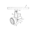
本実施の形態の照明器具は図1乃至4に示すように、天井部Tに設けられる配線ダクトレール(図示せず)に取り付けられるスポットライトであって、金属製の筐体1と、この筐体1に収容されるLEDパッケージ5を用いた光源とを有し、このLEDパッケージ5が実装される実装基板51と筐体1とが熱的に接続されており、筐体1の外周面が熱放射性部材で覆われたことを特徴とする。ここで筐体1は、前面の枠部2とこれに続く本体部7とで構成されており、枠部2も本体部7もアルミダイキャスト製の下地2a、7aに、高放熱塗料(ブラック)の塗布形成によって熱放射性部材2b、7bが形成されている。図1はこの照明器具の斜視図、図2は側面図、図3は要部破断断面図、図4は要部拡大断面図である。6はライティングプラグである。ここでLEDパッケージ5とは、LED素子を封止樹脂で被覆し、光源として用いられる発光素子をいうものとする。
(Embodiment 1)
As shown in FIGS. 1 to 4, the lighting fixture of the present embodiment is a spotlight attached to a wiring duct rail (not shown) provided on the ceiling T, and includes a metal casing 1 and the casing. A light source using the
この照明器具においては、光源としてLED(発光ダイオード)素子を実装したLEDパッケージを実装基板に実装し、筐体1と熱接触するように筐体1内に配置されている。このダウンライトにおいて、光の出射する方向にはポリカーボネート製集光レンズ54が配置され、LED素子52からの光を集光させ対象物への照射がなされる。
そしてこの実装基板51背面は絶縁性が高く熱伝導率の高いシリコン系の熱伝導シート53を介してアルミダイカスト製の下地7aに熱放射性部材7bが形成された本体部7に密着される。
In this lighting fixture, an LED package on which an LED (light emitting diode) element is mounted as a light source is mounted on a mounting substrate, and is disposed in the casing 1 so as to be in thermal contact with the casing 1. In this downlight, a
The back surface of the
なお、絶縁に問題がなければ、熱放射による放熱に加えて実装基板51とアルミダイカスト製の本体部7を直接接触させるようにして熱的接合を図るようにしてもよい。
If there is no problem with insulation, in addition to heat radiation by thermal radiation, the
アルミダイカスト製の本体部7は枠部2(外枠)を構成するダイカストに密着接合されている。集光レンズ54によりダイカストに実装基板51が押し付けられ、柔軟性のある熱伝導シート53によりダイカストに密着されることで熱抵抗の低減をはかることができる。LEDパッケージ5の発熱は枠部2および本体部7の下地2a、7aを構成するアルミダイカストに効率よく伝導され、この部位での冷却効率を高めることができれば、LEDパッケージ5の温度を下げることができ、発光効率の上昇や劣化による光束減退を抑え長寿命化およびコンパクト化が可能となる。
The
一般的に光源部を構成するLEDパッケージ5の温度上昇の抑制を図る場合、光源部上部の筐体1を熱伝導性の高い、例えばアルミのような素材で構成し、この上層に熱放射性材料からなる塗布膜からなる熱放射性部材2b、7bが器具外郭に露出する形で構成される。
このとき、アルミダイキャスト等の金属は熱伝導性に優れており(熱伝導率237 W・m-1・K-1 程度)、吸熱した熱を外枠に分散させ、外気への熱伝導で放熱を図ることができる。
しかし、一般的に赤外線放射率は0.03〜0.1程度と低く、放射での放熱には期待できない。
In general, when the temperature rise of the
At this time, metal such as aluminum die-casting has excellent thermal conductivity (thermal conductivity of about 237 W · m −1 · K −1 ), and the absorbed heat is dispersed in the outer frame, which allows heat conduction to the outside air. Heat dissipation can be achieved.
However, in general, the infrared emissivity is as low as about 0.03 to 0.1 and cannot be expected for heat dissipation by radiation.
そこで、アルミダイカスト等の金属で構成された前面の枠部2あるいは筐体の本体部の枠に高放熱性塗料、アクリル塗料にAl2O3、SiO2などを含有させ、少なくとも外面に塗装を施す。このときの塗布膜の平均塗装厚は20μm程度とするのが望ましい。20μm程度とすることで、放射性を発揮しつつかつ熱伝導性を低下させない様にすることが可能となる。
Therefore, the
ここで、塗装皮膜は膜厚が20μm程度と、薄いためアルミダイキャストからの熱伝導を大きく妨げることはない。実際に定常電圧を印加し無風で35℃定常状態の室内で温度が飽和するまで約3時間放置し表面温度を測定した。アクリル塗装のみの場合、塗装表面温度は最高温度で84℃であった。高熱放射性塗装を行った本実施の形態の照明器具の場合は79℃となり、5℃程度の温度の低減をはかることができた。 Here, since the coating film is as thin as about 20 μm, heat conduction from the aluminum die-casting is not greatly hindered. Actually, a steady voltage was applied, and the surface temperature was measured by leaving for about 3 hours until the temperature was saturated in a room at 35 ° C. with no wind. In the case of only acrylic coating, the maximum coating surface temperature was 84 ° C. In the case of the lighting apparatus of the present embodiment on which high thermal radiation coating was applied, the temperature was 79 ° C., and the temperature could be reduced by about 5 ° C.
このとき、高熱放射性塗装を形成する部位は、照明器具の器具外郭の放熱部全体ではなく、一部であり、ここでは前面の枠部2、本体部7である。
天井部Tに用いられる天井造営材としては塩化ビニールクロスなどを用いることが多く、このような天井造営材は、耐熱性が60度程度ときわめて低い。
このように天井造営材などの内装部材を照明器具からの放熱(熱放射)で痛めないようにするため、天井に近接する部分は塗布しない工夫をしている。
また、天井部が耐熱性の高い材料で構成されている場合には、本体まで熱放射性塗装を施し、更に放熱効率を上げることもできる。
At this time, the part where the high heat radiation coating is formed is not the entire heat radiating part of the outer shell of the lighting fixture, but a part thereof, and here is the
In many cases, a vinyl chloride cloth or the like is used as a ceiling construction material used for the ceiling portion T, and such a ceiling construction material has an extremely low heat resistance of about 60 degrees.
Thus, in order to prevent the interior members such as the ceiling construction material from being damaged by the heat radiation (heat radiation) from the lighting fixtures, the portion adjacent to the ceiling is not applied.
Moreover, when the ceiling part is comprised with the material with high heat resistance, heat radiation coating can be given to a main body, and also heat dissipation efficiency can also be raised.
また、照明器具内にLED素子を点灯させる点灯回路を内蔵して器具をコンパクト化する場合もある。
このときも、上記手法は有効となる。点灯回路は基板上に実装されている。基板は本体内面の凹凸部にセットされ、ねじもしくは金属板を介して本体に結合される。
従って、光源を点灯させるための点灯回路は大量の熱を発生するが、この点灯回路が筐体に収容され、熱的に接続されることで、熱放射性塗料の塗布された筐体の外周面から点灯回路からの熱を十分に放熱させることができる。
In some cases, the lighting device is made compact by incorporating a lighting circuit for lighting the LED element.
Also at this time, the above method is effective. The lighting circuit is mounted on the substrate. The substrate is set on the concavo-convex portion on the inner surface of the main body, and is coupled to the main body via screws or a metal plate.
Therefore, the lighting circuit for lighting the light source generates a large amount of heat, but this lighting circuit is housed in the housing and thermally connected, so that the outer peripheral surface of the housing to which the heat-radiating paint is applied Can sufficiently dissipate heat from the lighting circuit.
この構成によれば、光源が実装される実装基板と筐体とが熱的に接続されており、かつ筐体の外周面の一部に熱放射性塗料が塗布されているため、光源からの熱が確実に筐体に伝導される。そして、さらに熱放射性塗料により熱放射率が改善された筐体の外周面から十分に熱が放射され、十分な放熱を行うことができる。 According to this configuration, the mounting substrate on which the light source is mounted and the housing are thermally connected, and the thermal radiation paint is applied to a part of the outer peripheral surface of the housing. Is reliably conducted to the housing. Further, heat is sufficiently radiated from the outer peripheral surface of the housing whose thermal emissivity is improved by the thermal radiation paint, and sufficient heat dissipation can be performed.
(実施の形態2)
実施の形態2の照明器具としてのダウンライトは、図5乃至7に示すように、筐体で構成される本体部11の表面全体に熱放射性材料を用いて高放射塗装を行ったもので、取り付け孔に挿入されて、又は取り付け面に接触されて、固定されるものである。本実施の形態では、熱放射性部材11Sは、本体部11の外周面のうち、取り付け孔又は取り付け面に臨む部位を除いて配設される。図5は要部断面図、図6は上面図、図7は下面図である。
(Embodiment 2)
As shown in FIGS. 5 to 7, the downlight as the lighting fixture according to the second embodiment is obtained by performing high-radiation coating on the entire surface of the
本体部11は放熱フィンとLEDパッケージ15と接合する面にて構成されており、熱伝導率の高いアルミダイカストにて構成される。LEDパッケージ15はシリコン放熱シートを介して本体接合面に密着される。
本体部11に熱放射性部材を配して高放熱塗装を施した本実施の形態の照明器具の場合は、77℃となり、9℃の温度低減効果があった。
これに対し本体部11に塗装により熱放射性部材11Sを形成しなかった場合、上記同様条件にて穴あき木製ボードに設置し温度測定した場合、本体部11の最高温度部は86℃であった。
The
In the case of the lighting fixture of the present embodiment in which a heat radiating member is arranged on the
On the other hand, when the
枠部17は天井埋込穴に対しては、通常あそびをもって大きな穴を施工するため、一部天井材に接しているポイントをのぞいて0〜4mm程度の空間を介して設置される。
これは、器具成型精度・穴あけ施工精度の問題からある程度のあそびを前提として製造・施工されているためである。
The
This is because it is manufactured and constructed on the premise of a certain amount of play due to the problems of instrument molding accuracy and drilling construction accuracy.
天井材は石膏ボードのような耐火性のものや一般木材などさまざまな部材が用いられるが、木材の場合は一般的に引火点が240℃以上、低温着火点が100℃以上といわれており、器具点灯時も90℃以下にすることが望ましい。 The ceiling material is made of fire-resistant materials such as gypsum board and various materials such as general wood. In the case of wood, it is generally said that the flash point is 240 ° C or higher and the low temperature ignition point is 100 ° C or higher. It is desirable to keep it at 90 ° C. or lower even when it is lit.
この枠部をアルミダイキャストのような熱伝導性の高い素材で構成して表面に高放射性塗料を塗布した場合、枠部17近傍の天井材の温度上昇を増大させるため好ましくない。
実際に同じ条件で、ダウンライトの本体部11に熱放射性材料を用いて高放熱塗装し、枠部にも熱放射性材料を用いて高放熱塗装をした場合、天井材の開口部周辺の最高温度は92℃であった。
これに対し、ダウンライトの本体部11にのみ高放熱塗装し、アクリル塗装をした場合は、87℃であった。
If this frame portion is made of a material having high thermal conductivity such as aluminum die cast and a high-radiation paint is applied to the surface, the temperature rise of the ceiling material in the vicinity of the
Under the same conditions, if the heat radiation material is applied to the
On the other hand, when high heat radiation coating was applied only to the
よって、本体部11は樹脂などの熱伝導性の低い素材とするか、もしくは、アルミ等の熱伝導性の高い素材を使いつつ、通常塗装処理をするなどして天井材への熱供給を抑える構成とする。天井造営材に熱的影響の少ない本体部にのみ高放熱塗装をすることにより、造営材を保護しつつLED素子等の熱的許容限界にて器具設計をすることが可能となる。
Therefore, the
(実施の形態3)
実施の形態3の照明器具としてのシーリングライトは、図8乃至10に示すように、天井面に対向する面を除いてセード21を構成するアルミダイカストからなるセード本体21aの外表面に高放射塗装で形成した熱放射性部材21bを形成したものである。図8は斜視図、図9は分解斜視図、図10は要部断面図である。25はLEDパッケージである。
(Embodiment 3)
As shown in FIGS. 8 to 10, the ceiling light as the lighting apparatus according to the third embodiment has a high radiation coating on the outer surface of the shade
この構成によれば、天井面に面を向けている本体20には塗装をしないようにすることにより、天井面への熱的ダメージを避けることができる。
According to this configuration, it is possible to avoid thermal damage to the ceiling surface by not painting the
またセード本体21aをマグネタイトを含有する樹脂の成型体で構成し、セード自体を放熱性部材で構成するようにしてもよい。
Alternatively, the
なお、上記実施の形態1乃至3では、高放熱塗料としては、一般的な樹脂塗装、例えば、アクリル・シリコーン・メラミン・ポリエステル樹脂等の塗料材料に主に熱を赤外域の電磁波として放出する材料を混入させたものを用いる。含有させる材料としては、カーボンやAl2O3、SiO2、TiO2、ZrO2、Fe2O3、CuO、MgO、NiO、Li2O、CoOなどの金属酸化セラミック、Fe3O4などのマグネタイト、SnO2-Sb2O5が用いられる。 In the first to third embodiments, as the high heat dissipation paint, a general resin coating, for example, a material that mainly emits heat as an electromagnetic wave in the infrared region to a paint material such as acrylic, silicone, melamine, or polyester resin. Use a mixture of Examples of the material to be included include carbon, metal oxide ceramics such as Al 2 O 3 , SiO 2 , TiO 2 , ZrO 2 , Fe 2 O 3 , CuO, MgO, NiO, Li 2 O, and CoO, Fe 3 O 4, and the like. Magnetite, SnO 2 —Sb 2 O 5 is used.
また、熱放射性材料の含有率を傾斜させた構造も有効である。これはバルクとしての樹脂、塗装膜のいずれにも有効である。たとえば放熱性の良好なALNセラミックス内に金属タングステンW粒子を分散させ、分散比率を傾斜させるようにしてもよい。例えば、ALN/W系傾斜構造材料を用いることで、より高効率の熱放射性を得ることが可能となる。
このように、カーボン、金属酸化物セラミック、マグネタイトのいずれかを含有する樹脂からなる塗布膜を用いることにより、薄型で、放熱性の良好な照明器具を形成することができるが、必ずしも塗布膜に限定するものではなく、熱放射性に優れたフィルムで覆う、あるいは熱放射性材料の成形体で形成するなど適宜変形可能である。
Further, a structure in which the content of the heat radiating material is inclined is also effective. This is effective for both bulk resin and coating film. For example, metallic tungsten W particles may be dispersed in ALN ceramics having good heat dissipation properties, and the dispersion ratio may be inclined. For example, it is possible to obtain more efficient thermal radiation by using an ALN / W-based gradient structure material.
Thus, by using a coating film made of a resin containing any of carbon, metal oxide ceramics, and magnetite, it is possible to form a thin lighting device with good heat dissipation, but the coating film is not necessarily applied to the coating film. It is not limited, and it can be suitably modified such as covering with a film excellent in heat radiation or forming with a molded body of heat radiation material.
1 筐体
2 枠部
2a,7a 下地
2b,7b 熱放射性部材
5、15 LEDパッケージ
51 実装基板
54 集光レンズ
7 本体部
11 本体部
11S 熱放射性部材
21 セード
21a セード本体
21b 熱放射性部材
DESCRIPTION OF SYMBOLS 1
Claims (6)
前記光源が実装される実装基板と前記筐体とが熱的に接続されており、
前記筐体の外周面の少なくとも一部が熱放射性部材で覆われた照明器具。 A lighting fixture having a housing and a light source accommodated in the housing,
The mounting substrate on which the light source is mounted and the housing are thermally connected,
A lighting fixture in which at least a part of an outer peripheral surface of the casing is covered with a heat-radiating member.
前記筐体は、少なくとも表面が金属で形成された照明器具。 The lighting fixture according to claim 1,
The casing is a luminaire having at least a surface made of metal.
前記照明器具は、
前記光源を点灯させる点灯回路を有し、
前記点灯回路は前記筐体に収容され、かつ前記点灯回路と前記筐体とが熱的に接続される照明器具。 The lighting apparatus according to claim 1 or 2,
The lighting fixture is:
A lighting circuit for lighting the light source;
The lighting device is housed in the housing, and the lighting circuit and the housing are thermally connected.
前記照明器具は取り付け孔に挿入されて、又は取り付け面に接触されて、固定されるものであり、
前記放熱性部材は、前記筐体の外周面のうち、前記取り付け孔又は取り付け面に臨む部位を除いて配設される照明器具。 It is a lighting fixture in any one of Claims 1 thru | or 3, Comprising:
The lighting fixture is fixed by being inserted into a mounting hole or in contact with a mounting surface,
The said heat radiating member is a lighting fixture arrange | positioned except the site | part which faces the said attachment hole or an attachment surface among the outer peripheral surfaces of the said housing | casing.
前記熱放射性部材は、塗布膜である照明器具。 It is a lighting fixture in any one of Claims 1 thru | or 4, Comprising:
The said heat radiation member is a lighting fixture which is a coating film.
前記熱放射性部材は、カーボン、金属酸化物セラミック、マグネタイトのいずれかを含有する樹脂からなる塗布膜である照明器具。 It is a lighting fixture of Claim 5, Comprising:
The said heat radiation member is a lighting fixture which is a coating film which consists of resin containing any of carbon, a metal oxide ceramic, and a magnetite.
Priority Applications (1)
| Application Number | Priority Date | Filing Date | Title |
|---|---|---|---|
| JP2010036056A JP2011171237A (en) | 2010-02-22 | 2010-02-22 | Luminaire |
Applications Claiming Priority (1)
| Application Number | Priority Date | Filing Date | Title |
|---|---|---|---|
| JP2010036056A JP2011171237A (en) | 2010-02-22 | 2010-02-22 | Luminaire |
Publications (1)
| Publication Number | Publication Date |
|---|---|
| JP2011171237A true JP2011171237A (en) | 2011-09-01 |
Family
ID=44685122
Family Applications (1)
| Application Number | Title | Priority Date | Filing Date |
|---|---|---|---|
| JP2010036056A Withdrawn JP2011171237A (en) | 2010-02-22 | 2010-02-22 | Luminaire |
Country Status (1)
| Country | Link |
|---|---|
| JP (1) | JP2011171237A (en) |
Cited By (4)
| Publication number | Priority date | Publication date | Assignee | Title |
|---|---|---|---|---|
| CN104033746A (en) * | 2013-03-06 | 2014-09-10 | 深圳市鼎芯东方科技有限公司 | Novel ceramic LED (Light Emitting Diode) integrated bulb lamp |
| JP2016054140A (en) * | 2014-09-02 | 2016-04-14 | 周煥球Chou, Huan−Chiu | Internally reflective lighting fixture |
| JP2017033682A (en) * | 2015-07-29 | 2017-02-09 | 日亜化学工業株式会社 | Lighting device |
| JP2017199596A (en) * | 2016-04-28 | 2017-11-02 | アイリスオーヤマ株式会社 | Lighting device |
-
2010
- 2010-02-22 JP JP2010036056A patent/JP2011171237A/en not_active Withdrawn
Cited By (4)
| Publication number | Priority date | Publication date | Assignee | Title |
|---|---|---|---|---|
| CN104033746A (en) * | 2013-03-06 | 2014-09-10 | 深圳市鼎芯东方科技有限公司 | Novel ceramic LED (Light Emitting Diode) integrated bulb lamp |
| JP2016054140A (en) * | 2014-09-02 | 2016-04-14 | 周煥球Chou, Huan−Chiu | Internally reflective lighting fixture |
| JP2017033682A (en) * | 2015-07-29 | 2017-02-09 | 日亜化学工業株式会社 | Lighting device |
| JP2017199596A (en) * | 2016-04-28 | 2017-11-02 | アイリスオーヤマ株式会社 | Lighting device |
Similar Documents
| Publication | Publication Date | Title |
|---|---|---|
| JP5320555B2 (en) | Light emitting element lamp and lighting apparatus | |
| CN101737689B (en) | Recessed luminaire | |
| JP4569683B2 (en) | Light emitting element lamp and lighting apparatus | |
| CN101592295A (en) | Lighting device | |
| JP4919488B2 (en) | Lighting device | |
| JP4406854B2 (en) | Light emitting element lamp and lighting apparatus | |
| JP5126631B2 (en) | Light emitting element lamp and lighting apparatus | |
| JP2009266703A (en) | Embedded illumination fixture | |
| JP2011171237A (en) | Luminaire | |
| JP2012146552A (en) | Lighting device | |
| JP5575624B2 (en) | Lighting unit and lighting device | |
| JP2013037852A (en) | Lighting fixture | |
| JP5331511B2 (en) | LED lighting equipment | |
| JP5019264B2 (en) | Light emitting element lamp and lighting apparatus | |
| JP2010073569A (en) | Lamp device and illumination fixture | |
| JP2015008114A (en) | Lighting device | |
| JP2013118198A (en) | Illumination apparatus | |
| JP6043676B2 (en) | LED lighting device | |
| JP6019497B2 (en) | LED lighting device | |
| US20150077993A1 (en) | Lighting apparatus | |
| KR20100099520A (en) | Illuminator | |
| JP5887533B2 (en) | Recessed lighting fixture | |
| JP2012119090A (en) | Bulb type lamp and lighting fixture | |
| JP2011090846A (en) | LED lighting fixtures | |
| JP2010086750A (en) | Lamp device and illumination fixture |
Legal Events
| Date | Code | Title | Description |
|---|---|---|---|
| A711 | Notification of change in applicant |
Free format text: JAPANESE INTERMEDIATE CODE: A712 Effective date: 20120116 |
|
| A300 | Withdrawal of application because of no request for examination |
Free format text: JAPANESE INTERMEDIATE CODE: A300 Effective date: 20130507 |