JP2011190876A - Disk brake device - Google Patents
Disk brake device Download PDFInfo
- Publication number
- JP2011190876A JP2011190876A JP2010057964A JP2010057964A JP2011190876A JP 2011190876 A JP2011190876 A JP 2011190876A JP 2010057964 A JP2010057964 A JP 2010057964A JP 2010057964 A JP2010057964 A JP 2010057964A JP 2011190876 A JP2011190876 A JP 2011190876A
- Authority
- JP
- Japan
- Prior art keywords
- piston
- diameter
- cylinder hole
- hole
- outer peripheral
- Prior art date
- Legal status (The legal status is an assumption and is not a legal conclusion. Google has not performed a legal analysis and makes no representation as to the accuracy of the status listed.)
- Pending
Links
Images
Landscapes
- Sealing With Elastic Sealing Lips (AREA)
- Braking Arrangements (AREA)
- Sealing Of Bearings (AREA)
Abstract
【課題】アジャスタのピストンへの良好な組み付け性を確保しながら、ピストン先端部に形成していたエア抜き孔を省略することができるディスクブレーキ装置を提供する。
【解決手段】アジャストボルト13の小径ピストン13aは、シリンダ孔先端側大径部13cと、シリンダ孔底部側中径部13dと、カップシール15を嵌着する小径軸部13eとを有する。カップシール15は、小径軸部13eに嵌着される内周リップ部15aと、嵌合孔9aの内周面に弾接する外周リップ部15bと、外周リップ部15bと内周リップ部15aとを繋ぐベース部15cとを備え、真空保持圧以下の緊迫力に設定される。アジャストボルト13の小径ピストン13aをピストン9の嵌合孔9a内に挿入する際に、小径ピストン13aよりもピストン底壁側の嵌合孔内に形成される空間部E1のエアを、カップシール15の外周リップ部15bの外周側からシリンダ孔底部側に通過可能とする。
【選択図】図1Disclosed is a disc brake device capable of omitting an air vent hole formed in a tip end of a piston while ensuring good assembly of an adjuster to a piston.
A small-diameter piston 13a of an adjusting bolt 13 has a large-diameter portion 13c on a cylinder hole tip side, a medium-diameter portion 13d on a cylinder-hole bottom side, and a small-diameter shaft portion 13e on which a cup seal 15 is fitted. The cup seal 15 includes an inner peripheral lip portion 15a fitted to the small diameter shaft portion 13e, an outer peripheral lip portion 15b elastically contacting the inner peripheral surface of the fitting hole 9a, an outer peripheral lip portion 15b, and an inner peripheral lip portion 15a. And a base portion 15c to be connected, and is set to a tightening force equal to or lower than the vacuum holding pressure. When the small-diameter piston 13a of the adjusting bolt 13 is inserted into the fitting hole 9a of the piston 9, the air in the space E1 formed in the fitting hole closer to the piston bottom wall than the small-diameter piston 13a is supplied to the cup seal 15 It is possible to pass from the outer peripheral side of the outer peripheral lip portion 15b to the bottom side of the cylinder hole.
[Selection] Figure 1
Description
本発明は、ディスクブレーキ装置に関し、詳しくは、液圧によって摩擦パッドを押圧するピストンと、摩擦パッドとディスクロータとの間隙を自動調整するためのアジャスタと、推力変換機構により前記アジャスタを介してピストンを押圧するパーキングブレーキとを備えたディスクブレーキ装置に関する。 The present invention relates to a disc brake device, and more specifically, a piston that presses a friction pad by hydraulic pressure, an adjuster for automatically adjusting a gap between the friction pad and the disc rotor, and a piston through the adjuster by a thrust conversion mechanism. The present invention relates to a disc brake device provided with a parking brake that presses the.
四輪自動車等に用いられるディスクブレーキ装置として、ブレーキペダルによる液圧式作動機構と、ハンドレバーやフットペダルによって牽引操作される機械式作動機構とを備えたパーキングブレーキ付きのディスクブレーキ装置がある。このパーキングブレーキ付きのディスクブレーキ装置は、一般に、キャリパボディに設けたシリンダ孔の先端開口側に液圧式作動機構を構成するピストンを配置し、このピストンの後面側にアジャストナット及びアジャストボルトを有するアジャスタを配置すると共に、シリンダ孔の底部側に機械式作動機構を構成する推力変換機構を配置している。また、前記アジャスタは、シリンダ孔の先端開口側に配置されるアジャストナットとアジャストボルトの何れか一方の先端部に、シール材を装着した小径ピストンが形成されると共に、前記ピストンの底壁内面には、前記小径ピストンを前記シール材を介して嵌合する嵌合孔を備えていた。 As a disc brake device used for a four-wheeled vehicle or the like, there is a disc brake device with a parking brake that includes a hydraulic operation mechanism using a brake pedal and a mechanical operation mechanism that is pulled by a hand lever or a foot pedal. In this disc brake device with a parking brake, generally, a piston that constitutes a hydraulic operating mechanism is disposed on the end opening side of a cylinder hole provided in a caliper body, and an adjuster having an adjusting nut and an adjusting bolt on the rear surface side of the piston. And a thrust conversion mechanism that constitutes a mechanical operation mechanism is disposed on the bottom side of the cylinder hole. The adjuster is formed with a small-diameter piston fitted with a seal material at the tip of one of an adjustment nut and an adjustment bolt arranged on the tip opening side of the cylinder hole, and on the inner surface of the bottom wall of the piston. Had a fitting hole for fitting the small-diameter piston through the sealing material.
このような、パーキングブレーキ付きのディスクブレーキ装置では、前記アジャスタの小径ピストンを前記ピストンの嵌合孔内に挿入する際に、小径ピストンよりもピストン底壁側の嵌合孔内に形成される空間部の圧力を抜いて、小径ピストンを嵌合孔内に良好に挿入できるように、前記シール材が配置される位置よりもシリンダ孔開口側となるピストン先端部にエア抜き孔が穿設され、該エア抜き孔の開口部にはダストブーツが嵌着されているものがあった(例えば、特許文献1参照。)。 In such a disc brake device with a parking brake, when the small-diameter piston of the adjuster is inserted into the fitting hole of the piston, a space formed in the fitting hole on the piston bottom wall side than the small-diameter piston. In order to release the pressure of the part and insert the small-diameter piston into the fitting hole satisfactorily, an air vent hole is drilled in the piston tip part on the cylinder hole opening side from the position where the sealing material is disposed, Some openings of the air vent holes are fitted with dust boots (for example, see Patent Document 1).
しかし、上述のディスクブレーキ装置では、ピストンにエア抜き孔を加工する必要がありコストが嵩んでいた。また、作動液の充填時に油圧経路を真空引きし、前記シール材のシリンダ孔開口側とシリンダ孔底部側とに圧力差が生じた際に、エア抜き孔からピストン内に外気が入り込むことを防止するため、前記小径ピストンに装着する前記シール材は、例えば、大気圧以上の圧力差を生じても気密性を保持する緊迫力を備えていなければならなかった。さらに、エア抜き孔の開口部にダストブーツが嵌着され、エア抜き孔から水や塵芥がピストン内部に浸入しないようにしているが、ダストブーツのシール力が低い場合、エア抜き孔から水や塵芥がピストン内部に浸入する虞があった。 However, in the above-described disc brake device, it is necessary to process an air vent hole in the piston, which is expensive. Also, when the hydraulic fluid is filled, the hydraulic path is evacuated to prevent outside air from entering the piston through the air vent hole when a pressure difference occurs between the cylinder hole opening side and the cylinder hole bottom side of the sealing material. Therefore, for example, the sealing material to be mounted on the small-diameter piston has to have a tightening force that maintains hermeticity even when a pressure difference equal to or higher than atmospheric pressure occurs. In addition, dust boots are fitted into the openings of the air vent holes to prevent water and dust from entering the piston from the air vent holes. There was a risk that dust would enter the piston.
そこで本発明は、ピストンへのアジャスタの良好な組み付け性を確保しながら、ピストン先端部に形成していたエア抜き孔を省略することができるディスクブレーキ装置を提供することを目的としている。 SUMMARY OF THE INVENTION Accordingly, an object of the present invention is to provide a disc brake device that can omit the air vent hole formed in the tip of the piston while ensuring good assembly of the adjuster to the piston.
上記目的を達成するため、本発明のディスクブレーキ装置は、キャリパボディに形成されるシリンダ孔の先端開口側に、底壁をディスクロータ側に向けて収納されたピストンと、シリンダ孔の底部側に配設された推力変換機構と、該推力変換機構と前記ピストンとの間に設けられたアジャストナット及びアジャストボルトを有するアジャスタと、前記推力変換機構からアジャスタを介して前記ピストンを押動するパーキングブレーキとを備え、前記アジャスタは、前記シリンダ孔の先端開口側に配置される先端部に、シール材を装着した小径ピストンを備え、前記ピストンは、底壁内面に前記小径ピストンを前記シール材を介して嵌合する嵌合孔を備えた車両用ディスクブレーキ装置において、前記小径ピストンは、シリンダ孔先端側大径部とシリンダ孔底部側中径部と、該シリンダ孔底部側中径部と前記シリンダ孔先端側大径部との間に形成され、前記シール材を嵌着する小径軸部とを備え、前記シール材は、前記小径軸部に嵌着される内周リップ部と、前記嵌合孔の内周面に弾接する外周リップ部と、該外周リップ部と前記内周リップ部とを繋ぎ前記先端側大径部のシリンダ孔底部側面に当接するベース部とを備えた環状のカップシールで形成されると共に、前記外周リップ部は、前記カップシールのシリンダ孔開口側とシリンダ孔底部側とに圧力差が生じた際に、前記外周リップ部の外周面と前記嵌合孔の内周面との間が通気可能となる緊迫力に設定されていることを特徴とし、また、前記カップシールの外周面は、前記ベース部のシリンダ孔底部側から前記外周リップ部のシリンダ孔底部側端部に向けて漸次大径に形成される円錐部を備え、該円錐部のシリンダ軸方向の長さ寸法を、前記円錐部よりもシリンダ孔先端側に設けられる円筒部のシリンダ軸方向の長さ寸法よりも長く形成すると共に、前記外周リップ部は前記内周リップ部よりも薄肉に形成することもできる。 In order to achieve the above object, a disc brake device according to the present invention is provided on the tip opening side of a cylinder hole formed in a caliper body, on a piston housed with the bottom wall facing the disc rotor side, and on the bottom side of the cylinder hole. A disposed thrust converting mechanism; an adjuster having an adjusting nut and an adjusting bolt provided between the thrust converting mechanism and the piston; and a parking brake that pushes the piston from the thrust converting mechanism through the adjuster. The adjuster includes a small-diameter piston having a sealing material attached to a tip portion disposed on the tip opening side of the cylinder hole, and the piston has the small-diameter piston disposed on an inner surface of a bottom wall via the sealing material. In the vehicular disc brake device having a fitting hole for fitting, the small diameter piston is a large diameter portion on the tip end side of the cylinder hole. A cylinder hole bottom side medium diameter part; a cylinder hole bottom side medium diameter part; and a cylinder hole tip side large diameter part, and a small diameter shaft part into which the seal material is fitted, and the seal material The inner peripheral lip portion fitted to the small-diameter shaft portion, the outer peripheral lip portion elastically contacting the inner peripheral surface of the fitting hole, and the outer peripheral lip portion and the inner peripheral lip portion are connected to each other on the distal end side. The outer peripheral lip portion has a pressure difference between the cylinder hole opening side and the cylinder hole bottom side of the cup seal. When generated, the outer peripheral surface of the outer peripheral lip portion and the inner peripheral surface of the fitting hole are set to a tight force that allows ventilation, and the outer peripheral surface of the cup seal is , From the cylinder hole bottom side of the base portion, A cylinder of a cylindrical portion provided with a conical portion formed with a gradually increasing diameter toward the end portion on the bottom side of the Linda hole, and having a length dimension in the cylinder axial direction of the conical portion that is provided closer to the tip end side of the cylinder hole than the conical portion The outer circumferential lip portion can be formed to be thinner than the inner circumferential lip portion while being longer than the axial length.
本発明のディスクブレーキ装置によれば、アジャスタの小径ピストンをピストンの嵌合孔内に挿入する際に、ピストンシールが撓んで、小径ピストンよりもピストン底壁側の嵌合孔内に形成される空間部のエアを、ピストンシールの外周リップ部の外周側からシリンダ孔底部側に通過可能となることから、空間部の圧力を開放し、小径ピストンを嵌合孔内に良好に組み付けることができる。これにより、従来設けていたエア抜き孔を省略することができ、コストの削減化を図ることができ、さらに、従来のように、エア抜き孔から水や塵芥がピストン内部に浸入することがない。また、各部品を組み付けた後に、液圧系統を真空引きして作動液を充填する際にも、カップシールは、小径ピストンをピストンの嵌合孔に挿入する際と同様に撓み、空間部の圧力を開放することができる。 According to the disc brake device of the present invention, when the small-diameter piston of the adjuster is inserted into the fitting hole of the piston, the piston seal is bent and formed in the fitting hole on the piston bottom wall side than the small-diameter piston. Since the air in the space can be passed from the outer peripheral side of the outer peripheral lip of the piston seal to the bottom of the cylinder hole, the pressure in the space can be released and the small-diameter piston can be assembled well in the fitting hole. . As a result, the air vent hole provided in the past can be omitted, the cost can be reduced, and water or dust does not enter the piston from the air vent hole as in the conventional case. . Also, after assembling each part, when the hydraulic system is evacuated and filled with hydraulic fluid, the cup seal bends in the same way as when inserting the small diameter piston into the fitting hole of the piston, The pressure can be released.
さらに、カップシールの外周面に円錐部を備え、該円錐部のシリンダ軸方向の長さ寸法を、前記円錐部よりもシリンダ孔先端側に設けられる円筒部のシリンダ軸方向の長さ寸法よりも長く形成すると共に、外周リップ部を内周リップ部よりも薄肉に形成したことにより、小径ピストンを嵌合孔内に挿入する際に、前記ピストンシールが良好に撓み、前記空間部の圧力を容易に開放することができる。 Furthermore, the outer peripheral surface of the cup seal is provided with a conical portion, and the length in the cylinder axial direction of the conical portion is larger than the length in the cylinder axial direction of the cylindrical portion provided on the tip side of the cylinder hole than the conical portion. By forming the outer peripheral lip part thinner than the inner peripheral lip part, the piston seal is flexed well when the small-diameter piston is inserted into the fitting hole, and the pressure in the space part is easy. Can be opened.
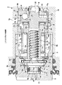
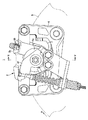
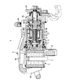
図1乃至図5に示すディスクブレーキ装置1は、キャリパボディ2にブレーキペダル(図示せず)にて操作させる液圧式作動機構3と、ハンドレバーやフットペダル(いずれも図示せず)にて操作されるパーキングブレーキ用の機械式作動機構4とを併設したパーキングブレーキ付きのディスクブレーキ装置であって、キャリパボディ2は、ディスクロータ5の一側部で車体に固設されるキャリパブラケット6に、図示しない一対の摺動ピンを介してディスク軸方向に移動可能に支持される。
The
前記キャリパボディ2は、ディスクロータ5の両側に対向配置される作用部2a及び反作用部2bと、ディスクロータ5の外側を跨いでこれらを連結するブリッジ部2cとを有しており、作用部2aと反作用部2bとの間には、一対の摩擦パッド7,7がディスクロータ5を挟んで配置されている。
The caliper body 2 includes an
作用部2aには、ディスクロータ側に開口するシリンダ孔8が形成されている。シリンダ孔8は、先端開口側に大径部8a、シリンダ孔底部側に小径部8bがそれぞれ形成され、大径部8aには開口側にシール溝8cとブーツ溝8dが周設され、小径部8bにはシリンダ軸方向に複数の係合溝8eが小径部8bの周方向に等間隔に設けられると共に、これら係合溝8eの軸方向中間部を繋ぐ周方向溝8fが形成されている。また、作用部2aの上部側には、前記係合溝8eの1つと、周方向溝8fとに連通し、車体取り付け時に、車体上方に位置するブリーダ孔8gが穿設されている。
A
シリンダ孔8の大径部8aには、液圧式作動機構3を構成する有底円筒状のピストン9が収容され、小径部8bには、機械式作動機構4を構成する推力変換機構10が収容されると共に、ピストン9と推力変換機構10との間には、ディスクロータ5と摩擦パッド7との制動間隙を自動的に調整するためのアジャスタ11が配設されている。また、シリンダ孔底壁8hには、固定側カム板12が配設されている。
The
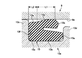
アジャスタ11は、アジャストボルト13とアジャストナット14とで構成され、アジャストボルト13の頭部には小径ピストン13aとクラッチ板13bとが設けられている。小径ピストン13aは、シリンダ孔先端側大径部13cと、シリンダ孔底部側中径部13dと、カップシール15を嵌着する小径軸部13eとを備え、該小径軸部13eは前記シリンダ孔先端側大径部13cと前記シリンダ孔底部側中径部13dとの間に形成されている。カップシール15は、環状に形成され、小径軸部13eに嵌着される内周リップ部15aと、ピストン9に形成した嵌合孔9aの内周面に弾接する外周リップ部15bと、外周リップ部15bと内周リップ部15aとを繋ぎ前記シリンダ孔先端側大径部13cのシリンダ孔底部側面13fに当接するベース部15cとを備えている。また、カップシール15の外周面は、ベース部15cのシリンダ孔底部側から外周リップ部15bのシリンダ孔底部側端部に向けて漸次大径に形成される円錐部15dを備え、該円錐部15dのシリンダ軸方向の長さ寸法L1を、円錐部15dよりもシリンダ孔先端側に設けられる円筒部15eのシリンダ軸方向の長さ寸法L2よりも長く形成すると共に、外周リップ部15bを内周リップ部15aよりも薄肉に形成し、外周リップ部15bは、カップシール15のシリンダ孔開口側とシリンダ孔底部側とに圧力差が生じた際に、円錐部15dの外周面と嵌合孔aの内周面との間が通気可能となる緊迫力に設定されている。なお、この外周リップ部15bの緊迫力は、大気圧の半分程度の圧力差を生じた際に、カップシール15のシリンダ孔開口側とシリンダ孔底部側とが通気可能となるように設定すると好適である。
The adjuster 11 includes an adjusting
アジャストナット14は、内部にアジャストボルト13と螺合する多条ねじ14aが形成され、シリンダ孔底部側の端部に推力伝達板14bが設けられている。また、アジャストナット14の外周側には、カムスプリング16と前記推力伝達板14bとを収容する円筒状のハウジング17がシリンダ孔8内に配設されている。
The
ピストン9は、底壁9bをディスクロータ側に向けてシリンダ孔8の大径部8aに収容されており、ピストン9の内部中心軸上に、前記アジャストナット14とアジャストボルト13とが設けられている。ピストン9の底壁内面には、前記嵌合孔9aが設けられ、嵌合孔9aに前記小径ピストン13aが前記カップシール15を介して嵌合し、クラッチ板13bは、嵌合孔9aの開口部から拡開する円錐面9cに、ばね部材18の作用で圧接している。また、ばね部材18は、一端がベアリング受け19に、他端がピストン9の内周壁に形成された止め輪装着溝9dに嵌着された止め輪20に当接し、ベアリング受け19及びベアリング21を介してアジャストボルト13を回動可能な状態で底壁9b側に付勢している。
The
前記推力変換機構10は、固定側カム板12に対して回動可能、且つ、シリンダ軸方向に移動可能に貫通したカムシャフト22と、該カムシャフト22のシリンダ孔開口側端部に設けられた駆動側カム板22aと該駆動側カム板22a及び前記固定側カム板12の対向位置にそれぞれ形成される複数のランプ溝23及び該ランプ溝23に収容されるカムベアリング24とを備えている。
The
駆動側カム板22aは、シリンダ孔開口側端部の中央に、円筒部22bが突設され、シリンダ孔開口側面に、スラストベアリング25とスペーサ26とを介して前記推力伝達板14bが当接する。
The driving
推力伝達板14bは、シリンダ孔底部側端部の中央に、前記円筒部22bと、アジャストボルト13のねじ部先端を収容する収容孔14cが形成され、また、外周には複数の係合用突部14dが周方向に等間隔で設けられている。
The
固定側カム板12は、円盤状に形成され、中央にはカムシャフト22を挿通させる挿通孔12aが設けられ、外周側にはシリンダ孔8の各係合溝8eにそれぞれ係合する複数の係合リブ12bが周方向に等間隔に突設されている。
The fixed-side cam plate 12 is formed in a disc shape, and is provided with an insertion hole 12a through which the
ハウジング17は、シリンダ孔8の小径部8bの径よりもやや小径に形成される大径筒部17aと、アジャストナット14に形成した推力伝達板14bの外径よりも大きな内径を有する小径筒部17bとを一体に備えたもので、小径筒部17bの周壁にはハウジング17の内外を貫通する通孔17cが穿設されると共に、小径筒部17bのシリンダ孔開口側から、大径筒部17aのシリンダ孔底部側に亘って、前記推力伝達板14bの各係合用突部14dが軸方向にのみ移動可能に係合する係合孔17dが穿設されている。さらに、小径筒部17bのシリンダ孔開口部側端部にはカムスプリング16の支持片17eが内周側に突設されている。大径筒部17aのシリンダ孔底部側には、シリンダ孔8の各係合溝8eにそれぞれ係合されると共に、周方向溝8fに嵌着する複数の係合リブ17fが周方向に等間隔で突設され、大径筒部17aの隣り合う係合リブ17f間の周壁は、シリンダ孔底部側に延設され、前記固定側カム板12の周壁に係合させる折曲げ片17gが形成されている。また、係合リブ17fのシリンダ孔底部側で、隣り合う折曲げ片17g間は、空隙部となっており、この空隙部が、ディスクブレーキ装置を組み立て後に、ハウジング17の内外を連通させる連通孔17hとなる。
The
このように形成した本形態例のディスクブレーキ装置1の組み付けは、ハウジング17のシリンダ孔底部側の開口から、カムスプリング16を挿入し、その一端を支持片17eに当接させ、カムスプリング16の内周にアジャストナット14を挿通する。該アジャストナット14に設けた推力伝達板14bのシリンダ孔開口側面にカムスプリング16の他端を当接させ、アジャストナット14の係合用突部14dをハウジング17の係合孔17dに係合させて、推力伝達板14bをシリンダ軸方向に移動可能な状態で回り止めする。次に、推力伝達板14bの収容孔14cに、スペーサ26とスラストベアリング25とを挿通した駆動側カム板22aの円筒部22bを収容させ、推力伝達板14bのシリンダ孔底部側面と駆動側カム板22aのシリンダ孔開口側面とをスペーサ26とスラストベアリング25とを介して当接させる。次いで、各カムベアリング24を各ランプ溝23に収容するように固定側カム板12の挿通孔12aにカムシャフト22を挿通し、固定側カム板12の係合リブ12bとハウジング17の係合リブ17fの位置をシリンダ軸方向に合わせ、ハウジング17の折曲げ片17gを固定側カム板12の周壁に係合させる。これにより、固定側カム板12がハウジング17のシリンダ孔底部側に配設され、推力変換機構10と、推力伝達板14bと、カムスプリング16とをハウジング17内に組み付けてユニット化することができ、また、固定側カム板12の係合リブ12bとハウジング17の係合リブ17fとは、同一のシリンダ軸方向線状にそれぞれ1つずつ配設される。
The
このように組み付けられたユニットは、固定側カム板12をシリンダ孔底壁8h側に向けてシリンダ孔8内に挿入され、固定側カム板12の係合リブ12bとハウジング17の係合リブ17fとを、シリンダ孔8の小径部8bに形成された係合溝8eにそれぞれ係合させると共に、ハウジング17の係合リブ17fを周方向溝8fに係合させ、固定側カム板12から突出したカムシャフト22をシリンダ孔底壁8hの挿通孔8iから外部に突出させる。このように、固定側カム板12の係合リブ12bとハウジング17の係合リブ17fとをシリンダ孔8の係合溝8eにそれぞれ係合させることによって、固定側カム板12とハウジング17の回動を規制する。また、ハウジング17に形成した連通孔17hが、ブリーダ孔8gに連通する前記係合溝8eの位置に配設され、ハウジング17の内部と前記ブリーダ孔8gとが、連通孔17hと係合溝8eとを介して連通する。
The unit assembled in this manner is inserted into the
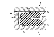
一方、アジャストボルト13は、小径軸部13eにカップシール15を嵌着し、クラッチ板13bのシリンダ孔底部側にベアリング21とベアリング受け19とばね部材18と止め輪20とを順に挿通した状態で、小径ピストン13aをピストン9の嵌合孔9aに挿入し、止め輪20をピストン9の内周壁に形成された止め輪装着溝9dに嵌着して、こちらも1つのユニットとする。小径ピストン13aを嵌合孔9aに挿入する際には、挿入に伴って小径ピストン13aのピストン底壁側に形成される嵌合孔9a内に形成される空間部E1の圧力が高くなると、カップシール15は、外周リップ部に設定されている緊迫力により、図3に示されるように、ベース部15c外周リップ部15bが内周リップ部側に撓み、カップシール15の外周面に形成した円錐部15dに沿って、空間部E1のエアが抜け、空間部E1内の圧力を開放することができる。これにより、小径ピストン13aを嵌合孔9a内に良好に挿入させることができる。さらに、円錐部15dのシリンダ軸方向の長さ寸法L1を、円錐部15dよりもシリンダ孔先端側に設けられた円筒部15eのシリンダ軸方向の長さ寸法L2よりも長く形成すると共に、外周リップ部15bを内周リップ部15aよりも薄肉に形成したことにより、カップシール15を、上述のように良好に撓ませることができる。また、カップシール15の外周側から抜けた空間部E1のエアは、嵌合孔9aとシリンダ孔底部側中径部13dとの隙間、クラッチ板13bと円錐面9cとの隙間、クラッチ板13bに形成された通孔13gを介してシリンダ孔底部側に抜ける。
On the other hand, the
次に、アジャストボルト13をアジャストナット14に螺合させながら、ピストン9をシリンダ孔8に押し込み、カムシャフト22の突出端に操作レバー27を取り付ける。これにより、キャリパボディ2に液圧式作動機構3,機械式作動機構4及びアジャスタ11が組み付けられる。
Next, the
このように組み付けられたディスクブレーキ装置1の液圧系統を真空引きして、作動液が充填されるが、この真空引き作業の際に、カップシール15は、小径ピストン13aをピストン9の嵌合孔9aに挿入する際と同様に撓み、空間部E1がエア抜きされる。
The hydraulic system of the
このディスクブレーキ装置1は、液圧式作動機構3を用いたブレーキ操作では、シリンダ孔8内に導入された作動液の圧力によってピストン9がディスクロータ方向に押動され、作用部2aの摩擦パッド7をディスクロータ5の一側面に押圧すると共に、その反力によってキャリパボディ2が作用部2a方向に移動し、反作用部2bが反作用部2b側の摩擦パッド7をディスクロータ5の他側面に押圧し、制動作用が行われる。
In this
この時、摩擦パッド7とディスクロータ5との制動間隙が所定範囲内にある場合は、ピストン9の移動量がアジャストボルト13とアジャストナット14とのバックラッシ分を移動するのみでアジャスト作用は行われない。摩擦パッド7の摩耗によってディスクロータ5との制動間隙が所定値を超えると、ピストン9が前記バックラッシ分を超えてディスクロータ側に大きく移動し、クラッチ板13bとピストン9の円錐面9cとが離れるが、アジャストボルト13が回って前進し、クラッチ板13bとピストン9の円錐面9cとは再び当接する。この状態でブレーキ操作を解除すると、ピストン9及びアジャストボルト13がバックラッシ分を後退することにより、摩擦パッド7とディスクロータ5との制動間隙が所定範囲に自動的に調節されることになる。
At this time, if the braking gap between the friction pad 7 and the disk rotor 5 is within a predetermined range, the adjusting operation is performed only by the movement amount of the
また、機械式作動機構4によるパーキングブレーキ操作では、ハンドレバーやフットペダルによって操作レバー27が回動操作されると、カムシャフト22と共に駆動側カム板22aが回動し、駆動側カム板22aの各ランプ溝23と固定側カム板12の各ランプ溝23との位相がずれることにより、各カムベアリング24がランプ溝23の浅い部分にそれぞれ移動し、固定側カム板12から駆動側カム板22aが離反するようにしてディスクロータ側に移動する。この駆動側カム板22aの軸方向の移動は、アジャストナット14からアジャストボルト13を介してピストン9に伝達され、該ピストン9をディスクロータ側に押動する推力となり、前記液圧式作動機構3による制動作用と同じようにして制動作用が行われる。
In the parking brake operation by the mechanical operation mechanism 4, when the
上述のディスクブレーキ装置1では、小径ピストン13aを嵌合孔9a内に挿入する際や液圧系統を真空引きする際に、カップシール15が撓んで、小径ピストン13aよりもピストン底壁側の嵌合孔9aに形成される空間部E1の圧力を開放することから、従来、ピストン9の底部側に形成していたエア抜き孔を省略することができ、コストの削減化を図ることができると共に、エア抜き孔から水や塵芥がピストン内部に浸入することがない。また、カップシール15の外周面に円錐部15dを備え、該円錐部15dのシリンダ軸方向の長さ寸法L1を、前記円錐部15dよりもシリンダ孔先端側に設けられた円筒部15eのシリンダ軸方向の長さ寸法L2よりも長く形成すると共に、外周リップ部15bを内周リップ部15aよりも薄肉に形成したことにより、小径ピストン13aを嵌合孔9a内に挿入する際や液圧系統を真空引きする際に、カップシール15が良好に撓み、前記空間部E1の圧力を容易に開放することができる。
In the
尚、本発明は上述の形態例のように、アジャストナットに推力伝達板を形成し、アジャストナットをハウジングに収容するようにするものに限らず、アジャストボルトに推力伝達板を形成し、アジャストボルトをハウジングに収容しても良い。 The present invention is not limited to the case where the thrust transmission plate is formed on the adjustment nut and the adjustment nut is accommodated in the housing as in the above-described embodiment, and the adjustment bolt is formed by forming the thrust transmission plate on the adjustment bolt. May be accommodated in a housing.
1…ディスクブレーキ装置、2…キャリパボディ、2…作用部、2…反作用部、2…ブリッジ部、3…液圧式作動機構、4…機械式作動機構、5…ディスクロータ、6…キャリパブラケット、7…摩擦パッド、8…シリンダ孔、8a…大径部、8b…小径部、8c…シール溝、8d…ブーツ溝、8e…係合溝、8f…周方向溝、8g…ブリーダ孔、8h…シリンダ孔底壁、8i…挿通孔、9…ピストン、9a…嵌合孔、9b…底壁、9c…円錐面、9d…止め輪装着溝、10…推力変換機構、11…アジャスタ、12…固定側カム板、12a…挿通孔、12b…係合リブ、13…アジャストボルト、13a…小径ピストン、13b…クラッチ板、13c…シリンダ孔先端側大径部、13d…シリンダ孔底部側中径部、13e…小径軸部、13f…シリンダ孔底部側面、14…アジャストナット、14a…多条ねじ、14b…推力伝達板、14c…収容孔、14d…係合用突部、15…カップシール、15a…内周リップ部、15b…外周リップ部、15c…ベース部、15d…円錐部、15e…円筒部、16…カムスプリング、17…ハウジング、17a…大径筒部、17b…小径筒部、17c…通孔、17d…係合孔、17e…支持片、17f…係合リブ、17g…折曲げ片、17h…連通孔、18…ばね部材、19…ベアリング受け、20…止め輪、21…ベアリング、22…カムシャフト、22a…駆動側カム板、22b…円筒部、23…ランプ溝、24…カムベアリング、25…スラストベアリング、26…スペーサ、27…操作レバー、28…ブリーダスクリュ
DESCRIPTION OF
Claims (2)
Priority Applications (1)
| Application Number | Priority Date | Filing Date | Title |
|---|---|---|---|
| JP2010057964A JP2011190876A (en) | 2010-03-15 | 2010-03-15 | Disk brake device |
Applications Claiming Priority (1)
| Application Number | Priority Date | Filing Date | Title |
|---|---|---|---|
| JP2010057964A JP2011190876A (en) | 2010-03-15 | 2010-03-15 | Disk brake device |
Publications (1)
| Publication Number | Publication Date |
|---|---|
| JP2011190876A true JP2011190876A (en) | 2011-09-29 |
Family
ID=44796012
Family Applications (1)
| Application Number | Title | Priority Date | Filing Date |
|---|---|---|---|
| JP2010057964A Pending JP2011190876A (en) | 2010-03-15 | 2010-03-15 | Disk brake device |
Country Status (1)
| Country | Link |
|---|---|
| JP (1) | JP2011190876A (en) |
Cited By (3)
| Publication number | Priority date | Publication date | Assignee | Title |
|---|---|---|---|---|
| CN103089869A (en) * | 2013-01-25 | 2013-05-08 | 徐浩钟 | Double-cavity separation type brake master cylinder |
| CN105276039A (en) * | 2015-11-05 | 2016-01-27 | 常州南车铁马科技实业有限公司 | Rail vehicle braking clamp |
| CN115539537A (en) * | 2022-11-09 | 2022-12-30 | 武汉万向汽车制动器有限公司 | EPB brake calipers |
-
2010
- 2010-03-15 JP JP2010057964A patent/JP2011190876A/en active Pending
Cited By (5)
| Publication number | Priority date | Publication date | Assignee | Title |
|---|---|---|---|---|
| CN103089869A (en) * | 2013-01-25 | 2013-05-08 | 徐浩钟 | Double-cavity separation type brake master cylinder |
| CN103089869B (en) * | 2013-01-25 | 2017-10-31 | 徐毓艺 | Double-cavity separation type brake master cylinder |
| CN105276039A (en) * | 2015-11-05 | 2016-01-27 | 常州南车铁马科技实业有限公司 | Rail vehicle braking clamp |
| CN115539537A (en) * | 2022-11-09 | 2022-12-30 | 武汉万向汽车制动器有限公司 | EPB brake calipers |
| CN115539537B (en) * | 2022-11-09 | 2023-09-29 | 武汉万向汽车制动器有限公司 | EPB brake caliper |
Similar Documents
| Publication | Publication Date | Title |
|---|---|---|
| US8069961B2 (en) | Disk brake apparatus | |
| KR930000191B1 (en) | Disk brake caliper assembly | |
| US8668057B2 (en) | Parking brake | |
| JP4823984B2 (en) | Disc brake device | |
| US8177038B2 (en) | Disk brake apparatus | |
| JPWO2016104685A1 (en) | Disc brake | |
| JP6602307B2 (en) | Drum brake device suitable for having a conventional parking brake or a parking brake operating in duo-servo mode | |
| WO2010024400A1 (en) | Disc brake | |
| JP2011052734A (en) | Disk brake | |
| JP4767227B2 (en) | Disc brake device | |
| JP2011190876A (en) | Disk brake device | |
| US5715916A (en) | Wheel brake assembly | |
| JP4355311B2 (en) | Disc brake device | |
| JP4674690B2 (en) | Disc brake | |
| JP2006002867A (en) | Disc brake device | |
| JP4782738B2 (en) | Disc brake device | |
| JP6448362B2 (en) | Disc brake | |
| KR101405190B1 (en) | Sealing member of disk type parking brake | |
| JP4381335B2 (en) | Disc brake device and method for forming cylinder hole in disc brake device | |
| JP4205073B2 (en) | Disc brake device | |
| JP2007146957A (en) | Disc brake device | |
| JP2006266296A (en) | Disc brake device and method for forming cylinder hole in disc brake device | |
| KR20160094139A (en) | Modular actuator and ball in ramp brake caliper type parking brake system | |
| KR20080023876A (en) | Car parking brake | |
| JP2005042753A (en) | Disc brake device |