JP2011192543A - Lithium ion secondary battery - Google Patents
Lithium ion secondary battery Download PDFInfo
- Publication number
- JP2011192543A JP2011192543A JP2010058092A JP2010058092A JP2011192543A JP 2011192543 A JP2011192543 A JP 2011192543A JP 2010058092 A JP2010058092 A JP 2010058092A JP 2010058092 A JP2010058092 A JP 2010058092A JP 2011192543 A JP2011192543 A JP 2011192543A
- Authority
- JP
- Japan
- Prior art keywords
- positive electrode
- porous layer
- negative electrode
- ion secondary
- lithium ion
- Prior art date
- Legal status (The legal status is an assumption and is not a legal conclusion. Google has not performed a legal analysis and makes no representation as to the accuracy of the status listed.)
- Pending
Links
Images
Classifications
-
- Y—GENERAL TAGGING OF NEW TECHNOLOGICAL DEVELOPMENTS; GENERAL TAGGING OF CROSS-SECTIONAL TECHNOLOGIES SPANNING OVER SEVERAL SECTIONS OF THE IPC; TECHNICAL SUBJECTS COVERED BY FORMER USPC CROSS-REFERENCE ART COLLECTIONS [XRACs] AND DIGESTS
- Y02—TECHNOLOGIES OR APPLICATIONS FOR MITIGATION OR ADAPTATION AGAINST CLIMATE CHANGE
- Y02E—REDUCTION OF GREENHOUSE GAS [GHG] EMISSIONS, RELATED TO ENERGY GENERATION, TRANSMISSION OR DISTRIBUTION
- Y02E60/00—Enabling technologies; Technologies with a potential or indirect contribution to GHG emissions mitigation
- Y02E60/10—Energy storage using batteries
-
- Y—GENERAL TAGGING OF NEW TECHNOLOGICAL DEVELOPMENTS; GENERAL TAGGING OF CROSS-SECTIONAL TECHNOLOGIES SPANNING OVER SEVERAL SECTIONS OF THE IPC; TECHNICAL SUBJECTS COVERED BY FORMER USPC CROSS-REFERENCE ART COLLECTIONS [XRACs] AND DIGESTS
- Y02—TECHNOLOGIES OR APPLICATIONS FOR MITIGATION OR ADAPTATION AGAINST CLIMATE CHANGE
- Y02P—CLIMATE CHANGE MITIGATION TECHNOLOGIES IN THE PRODUCTION OR PROCESSING OF GOODS
- Y02P70/00—Climate change mitigation technologies in the production process for final industrial or consumer products
- Y02P70/50—Manufacturing or production processes characterised by the final manufactured product
Landscapes
- Cell Electrode Carriers And Collectors (AREA)
- Cell Separators (AREA)
- Secondary Cells (AREA)
- Battery Electrode And Active Subsutance (AREA)
Abstract
【課題】 非水電解液の注液性を高め、これにより生産性を向上させたリチウムイオン二次電池を提供する。
【解決手段】 正極、負極、非水電解液およびセパレータを有するリチウムイオン二次電池であって、前記正極は、集電体であるアルミニウム箔の少なくとも一方の面に、リチウム含有複合酸化物を正極活物質として含む正極合剤層を有しており、前記正極の集電体を構成するアルミニウム箔は、表面の濡れ性が40mN/m以上であることを特徴とするリチウムイオン二次電池により、前記課題を解決する。
【選択図】 なしPROBLEM TO BE SOLVED: To provide a lithium ion secondary battery in which the liquid injection property of a non-aqueous electrolyte is improved and thereby the productivity is improved.
SOLUTION: A lithium ion secondary battery having a positive electrode, a negative electrode, a non-aqueous electrolyte, and a separator, wherein the positive electrode is formed of a lithium-containing composite oxide on at least one surface of an aluminum foil as a current collector. A lithium ion secondary battery having a positive electrode mixture layer containing as an active material, wherein the aluminum foil constituting the positive electrode current collector has a surface wettability of 40 mN / m or more, The problem is solved.
[Selection figure] None
Description
本発明は、注液性の良好なリチウムイオン二次電池に関するものである。 The present invention relates to a lithium ion secondary battery with good liquid injection properties.
近年、携帯機器の小型化・軽量化や高性能化に伴い、電源となるリチウムイオン二次電池の高性能化および安全性向上の要請が高まっている。また、リチウムイオン二次電池では、電気自動車や電動式自転車など、大型や中型のサイズでの用途も広がりを見せている。 In recent years, with the reduction in size, weight, and performance of portable devices, there is an increasing demand for higher performance and improved safety of lithium ion secondary batteries that serve as power sources. Lithium-ion secondary batteries are also expanding their use in large and medium sizes such as electric cars and electric bicycles.
このように、リチウムイオン二次電池は、その需要が高まりを見せていることから、その生産量が年々増え続けており、これに付随して低コスト化への期待も大きい。リチウムイオン二次電池における供給量の増大と低コスト化の両方のニーズに応えるには、その生産効率を改善することが求められる。 Thus, since the demand for lithium ion secondary batteries is increasing, the production volume thereof continues to increase year by year, and there is a great expectation for cost reduction. In order to meet the needs of both supply increase and cost reduction in lithium ion secondary batteries, it is required to improve production efficiency.
リチウムイオン二次電池の生産性を高める要因はいくつもあるが、例えば、非水電解液の注液性を高めることは、最も重要な改善項目といえる。その理由としては、非水電解液には揮発性の高い有機溶媒が使用されているために、注液工程中に非水電解液組成が変動しないように短時間で注液を完了することが求められることや、均一かつ十分に非水電解液を電極に浸透させることが、電池性能に大きな影響を与えることなどが挙げられる。 There are a number of factors that increase the productivity of the lithium ion secondary battery. For example, increasing the liquid injection property of the non-aqueous electrolyte is the most important improvement item. The reason for this is that since a highly volatile organic solvent is used for the non-aqueous electrolyte, the injection can be completed in a short time so that the composition of the non-aqueous electrolyte does not fluctuate during the injection process. What is required is that the non-aqueous electrolyte is uniformly and sufficiently permeated into the electrode, which greatly affects the battery performance.
昨今のリチウムイオン二次電池では、例えば、集電体となる金属箔などの片面または両面に、活物質を含む電極合剤層を形成した電極が使用されているが、高容量化の観点から、電極合剤層における活物質の高充填化(電極合剤層の高密度化)が図られている。特に正極は、反応源となるリチウムを含んだ酸化物が活物質として使用されるため、より高充填にして電池内へ挿入する必要がある。電極合剤層を高密度化すると、その空孔率が必然的に減少し、それに伴って非水電解液の電極合剤層における浸透性が低下する。電極合剤層への非水電解液の浸透性が低下すると、電池製造時の非水電解液注入工程において、多大な時間と労力を払うことになり、また、非水電解液の浸透が不十分となることで、電池間での特性にばらつきが生じて、歩留まりが低下するため、電池の生産性が低下するといった問題がある。 In recent lithium ion secondary batteries, for example, an electrode in which an electrode mixture layer containing an active material is formed on one or both sides of a metal foil or the like as a current collector is used. The active material in the electrode mixture layer is highly filled (the electrode mixture layer has a higher density). In particular, in the positive electrode, since an oxide containing lithium as a reaction source is used as an active material, it is necessary to insert it into the battery with higher filling. When the density of the electrode mixture layer is increased, the porosity is inevitably reduced, and accordingly, the permeability of the nonaqueous electrolytic solution in the electrode mixture layer is lowered. If the permeability of the non-aqueous electrolyte into the electrode mixture layer decreases, a great amount of time and labor will be spent in the non-aqueous electrolyte injection process at the time of battery production, and the penetration of the non-aqueous electrolyte will not be possible. If sufficient, there will be variations in the characteristics between the batteries, resulting in a decrease in yield, and there is a problem in that the productivity of the batteries decreases.
こうしたことから、電池製造時における非水電解液の注液性を改善して、その生産性を高める検討がなされている(例えば、特許文献1、2)。
For these reasons, studies have been made to improve the liquid injection property of the non-aqueous electrolyte during battery production and increase the productivity (for example,
本発明は、従来とは異なる手段によって非水電解液の注液性を高め、これにより生産性を向上させたリチウムイオン二次電池を提供することを目的とする。 An object of the present invention is to provide a lithium ion secondary battery in which the injection property of a non-aqueous electrolyte is improved by means different from the conventional one, thereby improving the productivity.
前記目的を達成し得た本発明のリチウムイオン二次電池は、正極、負極、非水電解液およびセパレータを有しており、前記正極は、集電体であるアルミニウム箔の少なくとも一方の面に、リチウム含有複合酸化物を正極活物質として含む正極合剤層を有しており、前記正極の集電体を構成するアルミニウム箔は、表面の濡れ性が40mN/m以上であることを特徴とするものである。 The lithium ion secondary battery of the present invention that has achieved the above object has a positive electrode, a negative electrode, a non-aqueous electrolyte, and a separator, and the positive electrode is on at least one surface of an aluminum foil that is a current collector. And a positive electrode mixture layer containing a lithium-containing composite oxide as a positive electrode active material, and the aluminum foil constituting the positive electrode current collector has a surface wettability of 40 mN / m or more. To do.
本発明によれば、非水電解液の注液性を高め、これにより生産性を向上させたリチウムイオン二次電池を提供することができる。 According to the present invention, it is possible to provide a lithium ion secondary battery in which the liquid-injecting property of the non-aqueous electrolyte is improved and thereby the productivity is improved.
本発明のリチウムイオン二次電池に係る正極は、集電体であるアルミニウム箔の片面または両面に、リチウム含有複合酸化物を正極活物質とする正極合剤層を有している。そして、正極集電体となるアルミニウム箔は、表面の濡れ性が40mN/m以上である。 The positive electrode according to the lithium ion secondary battery of the present invention has a positive electrode mixture layer using a lithium-containing composite oxide as a positive electrode active material on one or both sides of an aluminum foil as a current collector. The aluminum foil serving as the positive electrode current collector has a surface wettability of 40 mN / m or more.
正極集電体に使用されるアルミニウム箔は、通常、圧延工程を経て製造されるが、その圧延時に使用される油が表面に残存しやすく、これにより表面の濡れ性が、例えば31〜33mN/m程度となる。このように表面の濡れ性が低いアルミニウム箔を用いて構成した正極では、正極合剤層中に非水電解液が浸透し難いため、これを用いて電池を製造すると、非水電解液を注入(以下、「注液」ともいう)し難く、その工程に時間がかかったり、正極合剤層中に非水電解液が均一かつ十分に浸透せずに、特性の低い電池の製造割合が増大したりして、生産性が損なわれる場合がある。 The aluminum foil used for the positive electrode current collector is usually manufactured through a rolling process, but the oil used at the time of rolling tends to remain on the surface, whereby the wettability of the surface is, for example, 31 to 33 mN / m. In the positive electrode configured using the aluminum foil having low surface wettability in this way, the non-aqueous electrolyte does not easily penetrate into the positive electrode mixture layer. Therefore, when a battery is manufactured using this, the non-aqueous electrolyte is injected. (Hereinafter referred to as “injection”) is difficult, and the process takes time, and the non-aqueous electrolyte does not penetrate uniformly and sufficiently into the positive electrode mixture layer. As a result, productivity may be impaired.
そこで、本発明では、正極の集電体となるアルミニウム箔の表面の濡れ性を40mN/mとすることで、正極合剤層への非水電解液の浸透性を高めて、電池の生産性向上を達成した。すなわち、表面の濡れ性が40mN/m以上のアルミニウム箔を集電体とする正極では、集電体と正極合剤層との界面に非水電解液が効率よく且つ迅速に回り込み、その結果、正極合剤層内への非水電解液の浸透が促進されて、その浸透性が向上する。また、本発明のリチウムイオン二次電池では、正極合剤層中に非水電解液が均一かつ十分に浸透し得るため、電池の充放電特性自体も良好となる。 Therefore, in the present invention, the wettability of the surface of the aluminum foil serving as the positive electrode current collector is set to 40 mN / m, thereby increasing the permeability of the non-aqueous electrolyte into the positive electrode mixture layer, thereby improving the productivity of the battery. Achieved improvement. That is, in the positive electrode having a current collector of aluminum foil having a surface wettability of 40 mN / m or more, the non-aqueous electrolyte efficiently and quickly wraps around the interface between the current collector and the positive electrode mixture layer. The penetration of the non-aqueous electrolyte into the positive electrode mixture layer is promoted, and the permeability is improved. Further, in the lithium ion secondary battery of the present invention, the non-aqueous electrolyte can penetrate uniformly and sufficiently into the positive electrode mixture layer, so that the charge / discharge characteristics of the battery itself are also good.
正極の集電体となるアルミニウム箔の表面の濡れ性は60mN/m以上であることが好ましく、これにより、正極合剤層の密度が非常に高い場合(例えば、3.8g/cm3以上)でも、非水電解液の注液性が良好な電池とすることができる。 The wettability of the surface of the aluminum foil serving as the positive electrode current collector is preferably 60 mN / m or more, whereby the density of the positive electrode mixture layer is very high (for example, 3.8 g / cm 3 or more). However, it is possible to obtain a battery in which the non-aqueous electrolyte has good liquid injection properties.
アルミニウム箔の表面の濡れ性は、Wilhelmy法により、市販の装置(例えば、協和界面科学社製「CBVP−Z」)を用いて測定することができる。 The wettability of the surface of the aluminum foil can be measured by a Wilhelmy method using a commercially available device (for example, “CBVP-Z” manufactured by Kyowa Interface Science Co., Ltd.).
アルミニウム箔の表面の濡れ性は、例えば、有機溶剤(例えば、後述する非水電解液に用いる有機溶媒、具体的には、エチレンカーボネート、プロピレンカーボネート、ブチレンカーボネート、ビニレンカーボネートなどの環状カーボネート;ジメチルカーボネート、ジエチルカーボネート、メチルエチルカーボネートなどの鎖状カーボネート;プロピオン酸メチルなどの鎖状エステル;γ−ブチロラクトンなどの環状エステル;ジメトキシエタン、ジエチルエーテル、1,3−ジオキソラン、ジグライム、トリグライム、テトラグライムなどの鎖状エーテル;ジオキサン、テトラヒドロフラン、2−メチルテトラヒドロフランなどの環状エーテル;アセトニトリル、プロピオニトリル、メトキシプロピオニトリルなどのニトリル類;エチレングリコールサルファイトなどの亜硫酸エステル類;など)による洗浄や、アルミニウム箔の焼鈍処理、アルミニウム箔の表面処理(コロナ放電処理など)によって前記の値に調整することができる。 The wettability of the surface of the aluminum foil is, for example, an organic solvent (for example, an organic solvent used in a non-aqueous electrolyte described later, specifically, cyclic carbonates such as ethylene carbonate, propylene carbonate, butylene carbonate, vinylene carbonate; dimethyl carbonate Chain carbonates such as methyl carbonate, diethyl carbonate and methyl ethyl carbonate; chain esters such as methyl propionate; cyclic esters such as γ-butyrolactone; dimethoxyethane, diethyl ether, 1,3-dioxolane, diglyme, triglyme, tetraglyme Chain ethers; Cyclic ethers such as dioxane, tetrahydrofuran and 2-methyltetrahydrofuran; Nitriles such as acetonitrile, propionitrile and methoxypropionitrile; Ethylene Sulfites such as glycol sulfite; etc.) cleaning and by annealing treatment of aluminum foil, it can be adjusted to a value of the by surface treatment of the aluminum foil (such as corona discharge treatment).
アルミニウム箔の形状は、従来から知られているリチウムイオン二次電池で正極の集電体に使用されているものと同等でよく、例えば、厚みは10〜30μmであることが好ましい。また、アルミニウム箔の幅は、例えば、正極合剤含有組成物(後述する)を塗布する塗布機の仕様に合わせて、30〜100cmなどとすることができる。なお、本発明に係るアルミニウム箔は、本発明の効果を損なわない範囲で、アルミニウム以外の金属元素を含むアルミニウム(アルミニウム合金)により構成されていてもよい。 The shape of the aluminum foil may be the same as that used for a positive electrode current collector in a conventionally known lithium ion secondary battery. For example, the thickness is preferably 10 to 30 μm. Moreover, the width | variety of aluminum foil can be 30-100 cm etc. according to the specification of the coating device which apply | coats a positive mix containing composition (after-mentioned), for example. In addition, the aluminum foil which concerns on this invention may be comprised with the aluminum (aluminum alloy) containing metal elements other than aluminum in the range which does not impair the effect of this invention.
前記のアルミニウム箔からなる集電体の表面に形成される正極合剤層は、正極活物質の他にバインダや導電助剤を含む正極合剤により構成される。 The positive electrode mixture layer formed on the surface of the current collector made of the aluminum foil is composed of a positive electrode mixture containing a binder and a conductive additive in addition to the positive electrode active material.
正極活物質には、従来から知られているリチウムイオン二次電池に使用されているもの、すなわち、Li(リチウム)イオンを吸蔵放出可能なリチウム含有複合酸化物が使用される。具体的には、例えば、Li1+xMO2(−0.1<x<0.1、M:Co、Ni、Mn、Al、Mgなど。なお、元素MはLi以外の他の金属元素で10原子%まで置換されていてもよい。)で表される層状構造のリチウム含有遷移金属酸化物、LiMn2O4やその元素の一部を他元素で置換したスピネル構造のリチウムマンガン酸化物、LiMPO4(M:Co、Ni、Mn、Feなど)で表されるオリビン型化合物などを用いることが可能である。前記層状構造のリチウム含有遷移金属酸化物の具体例としては、LiCoO2やLiNi1−xCox−yAlyO2(0.1≦x≦0.3、0.01≦y≦0.2)などのほか、少なくともCo、NiおよびMnを含む酸化物(LiMn1/3Ni1/3Co1/3O2、LiMn5/12Ni5/12Co1/6O2、LiNi3/5Mn1/5Co1/5O2など)などを例示することができる。特に、Niを40%以上含む活物質の場合には、電池が高容量となるので好ましく、また、O(酸素原子)はフッ素、イオウ原子で1原子%まで置換されていてもよい。 As the positive electrode active material, those conventionally used for lithium ion secondary batteries, that is, lithium-containing composite oxides capable of occluding and releasing Li (lithium) ions are used. Specifically, for example, Li 1 + x MO 2 (−0.1 <x <0.1, M: Co, Ni, Mn, Al, Mg, etc. Note that the element M is a metal element other than Li and is 10 Lithium-containing transition metal oxide having a layered structure represented by the following formula: LiMn 2 O 4 or a part of its element substituted with another element, Limanganese oxide having a spinel structure, LiMPO 4 (M: Co, Ni, Mn, Fe, etc.) represented by an olivine type compound can be used. Specific examples of the lithium-containing transition metal oxide having a layered structure include LiCoO 2 and LiNi 1-x Co xy Al y O 2 (0.1 ≦ x ≦ 0.3, 0.01 ≦ y ≦ 0. 2) and other oxides containing at least Co, Ni and Mn (LiMn 1/3 Ni 1/3 Co 1/3 O 2 , LiMn 5/12 Ni 5/12 Co 1/6 O 2 , LiNi 3 / 5 Mn 1/5 Co 1/5 O 2 etc.). In particular, an active material containing 40% or more of Ni is preferable because the battery has a high capacity, and O (oxygen atom) may be substituted with 1 atom% of fluorine or sulfur atom.
正極合剤層に係るバインダとしては、例えば、ポリフッ化ビニリデン(PVDF)、ポリテトラフルオロエチレン(PTFE)、スチレンブタジエンゴム(SBR)、カルボキシメチルセルロース(CMC)などが好適に用いられる。また、正極合剤層に係る導電助剤としては、例えば、天然または人造の黒鉛、カーボンブラック、炭素繊維、カーボンナノチューブなどが好適に用いられる。 As the binder related to the positive electrode mixture layer, for example, polyvinylidene fluoride (PVDF), polytetrafluoroethylene (PTFE), styrene butadiene rubber (SBR), carboxymethyl cellulose (CMC) and the like are preferably used. Moreover, as a conductive support agent which concerns on a positive mix layer, natural or artificial graphite, carbon black, carbon fiber, a carbon nanotube etc. are used suitably, for example.
正極は、例えば、正極活物質、バインダおよび導電助剤を、N−メチル−2−ピロリドン(NMP)などの溶剤に分散させたペースト状やスラリー状の正極合剤含有組成物を調製し(ただし、バインダは溶剤に溶解していてもよい)、これを前記のアルミニウム箔からなる集電体の片面または両面に塗布し、乾燥した後に、必要に応じてカレンダー処理を施す工程を経て製造される。ただし、正極の製造方法は、前記の方法に制限される訳ではなく、他の製造方法で製造してもよい。 For the positive electrode, for example, a paste-like or slurry-like positive electrode mixture-containing composition in which a positive electrode active material, a binder, and a conductive additive are dispersed in a solvent such as N-methyl-2-pyrrolidone (NMP) is prepared. The binder may be dissolved in a solvent), and this is applied to one or both sides of the current collector made of the aluminum foil, dried, and then subjected to a calendering process as necessary. . However, the manufacturing method of the positive electrode is not limited to the above method, and may be manufactured by other manufacturing methods.
正極合剤層の厚みは、例えば、集電体の片面あたり10〜100μmであることが好ましい。また、正極合剤層の組成としては、例えば、正極活物質の量が60〜95質量%であることが好ましく、バインダの量が1〜15質量%であることが好ましく、導電助剤の量が3〜20質量%であることが好ましい。 The thickness of the positive electrode mixture layer is preferably, for example, 10 to 100 μm per one side of the current collector. Moreover, as a composition of a positive mix layer, it is preferable that the quantity of a positive electrode active material is 60-95 mass%, for example, it is preferable that the quantity of a binder is 1-15 mass%, and the quantity of a conductive support agent. Is preferably 3 to 20% by mass.
本発明のリチウムイオン二次電池に係る負極には、集電体の片面または両面に、負極活物質やバインダなどを含む負極合剤層を形成したものが使用できる。負極活物質は、従来から知られているリチウムイオン二次電池に使用されているもの、すなわち、Li(リチウム)イオンを吸蔵放出可能な活物質であれば、特に制限はない。具体的には、例えば、天然黒鉛、熱分解炭素類、コークス類、ガラス状炭素類、有機高分子化合物の焼成体、メソカーボンマイクロビーズ(MCMB)、炭素繊維などの炭素材料などが挙げられ、黒鉛質材料(天然黒鉛や、熱分解炭素類、MCMB、炭素繊維などの易黒鉛化炭素を2800℃以上で黒鉛化処理したもの)が特に好ましい。 As the negative electrode according to the lithium ion secondary battery of the present invention, one in which a negative electrode mixture layer containing a negative electrode active material or a binder is formed on one side or both sides of a current collector can be used. The negative electrode active material is not particularly limited as long as it is a conventionally used lithium ion secondary battery, that is, an active material capable of occluding and releasing Li (lithium) ions. Specifically, for example, natural graphite, pyrolytic carbons, cokes, glassy carbons, fired bodies of organic polymer compounds, mesocarbon microbeads (MCMB), carbon materials such as carbon fibers, etc. Graphite materials (natural graphite, pyrolytic carbons, MCMB, carbon fiber and other graphitized carbon obtained by graphitizing at 2800 ° C. or higher) are particularly preferable.
また、負極合剤層に係るバインダには、正極合剤層用のバインダとして先に例示した各種バインダと同じものが使用できる。更に、負極合剤層には、導電助剤として、アセチレンブラックなどの各種カーボンブラックやカーボンナノチューブなどを添加してもよい。 Moreover, the binder which concerns on a negative mix layer can use the same thing as the various binders illustrated previously as a binder for positive mix layers. Furthermore, you may add various carbon blacks, such as acetylene black, a carbon nanotube, etc. to a negative mix layer as a conductive support agent.
なお、本発明のリチウムイオン二次電池においては、負極合剤層表面の算術平均粗さ(Ra)が0.7μm以上の負極を用いることが好ましい。このような負極を用いると、負極表面のエンボス効果によって負極合剤層への非水電解液の浸透性も向上する。 In the lithium ion secondary battery of the present invention, it is preferable to use a negative electrode having an arithmetic average roughness (Ra) of 0.7 μm or more on the surface of the negative electrode mixture layer. When such a negative electrode is used, the permeability of the non-aqueous electrolyte into the negative electrode mixture layer is also improved by the embossing effect on the negative electrode surface.
ただし、表面粗度の大きな電極を用いると、電池内において、電極の凸部がセパレータにくい込んで、これと対向する電極との距離が縮まり、電池の充放電を繰り返し行うと、容量が低下しやすくなることがあり、極端な場合には、短絡することも予想される。また、表面粗度の大きな電極を、例えば突刺強度の低いセパレータと併用した場合には、電極の凸部がトリガーとなって、落下、振動などの衝撃が電池にかかった際に、セパレータが裂けて電極間が短絡することもある。よって、負極合剤層の表面粗度をある程度抑えて、電池の信頼性低下を抑制することが好ましい。具体的には、負極合剤層表面の算術平均粗さ(Ra)を1.2μm以下とすることが好ましく、この場合、例えば、後述する多孔質層(I)と多孔質層(II)とを有する積層型のセパレータを使用すれば、前記の理由による電池の信頼性低下を十分に抑制することができる。 However, when an electrode with a large surface roughness is used, the convex portion of the electrode is difficult to separate in the battery, the distance between the electrode and the opposite electrode is reduced, and the capacity decreases when the battery is repeatedly charged and discharged. In extreme cases, a short circuit is expected. In addition, when an electrode with a large surface roughness is used in combination with a separator having a low puncture strength, for example, the protruding portion of the electrode serves as a trigger and the separator tears when an impact such as dropping or vibration is applied to the battery. In some cases, the electrodes may be short-circuited. Therefore, it is preferable that the surface roughness of the negative electrode mixture layer is suppressed to some extent to suppress a decrease in battery reliability. Specifically, the arithmetic average roughness (Ra) of the negative electrode mixture layer surface is preferably 1.2 μm or less. In this case, for example, the porous layer (I) and the porous layer (II) described later If a laminated separator having the above is used, a decrease in battery reliability due to the above-described reason can be sufficiently suppressed.
なお、本明細書でいう負極合剤層表面の算術平均粗さ(Ra)は、JIS B 0601に規定の算術平均粗さであり、具体的には、共焦点レーザー顕微鏡(レーザテック株式会社製「リアルタイム走査型レーザ顕微鏡 1LM−21D」)を用い、1mm×1mmの視野を512×512ピクセルで測定し、各点の平均線からの絶対値を算術平均することにより求められる数値である。 In addition, the arithmetic mean roughness (Ra) of the negative electrode mixture layer surface referred to in the present specification is the arithmetic mean roughness defined in JIS B 0601, and specifically, a confocal laser microscope (manufactured by Lasertec Corporation). “Real-time scanning laser microscope 1LM-21D”) is used to measure a visual field of 1 mm × 1 mm with 512 × 512 pixels, and the numerical value is obtained by arithmetically averaging the absolute values from the average line of each point.
負極合剤層表面の算術平均粗さ(Ra)が0.7μm以上1.2μm以下である負極としては、例えば、表面が低結晶性の炭素材で被覆された黒鉛を負極活物質とした負極が挙げられ、更に具体的には、アルゴンイオンレーザーラマンスペクトルにおける1580cm−1のピーク強度に対する1360cm−1のピーク強度比であるR値(I1360/I1580)が0.1以上0.5以下であり、002面の面間隔d002が0.338nm以下である黒鉛質炭素を負極活物質として含む負極が挙げられる。この種の黒鉛質炭素は、負荷特性に優れ、特に0℃以下の低温での充電特性に優れる特長も有していることから、負極活物質として特に好ましく使用される。 Examples of the negative electrode having an arithmetic average roughness (Ra) on the surface of the negative electrode mixture layer of 0.7 μm or more and 1.2 μm or less include a negative electrode using graphite whose surface is coated with a low crystalline carbon material as a negative electrode active material and the like, and more specifically, R value is the peak intensity ratio of 1360 cm -1 to the peak intensity of 1580 cm -1 in the argon ion laser Raman spectrum (I 1360 / I 1580) of 0.1 to 0.5 And a negative electrode containing, as a negative electrode active material, graphitic carbon having a 002 plane spacing d 002 of 0.338 nm or less. This type of graphitic carbon is particularly preferably used as a negative electrode active material because it has excellent load characteristics, and particularly has excellent characteristics of charging at a low temperature of 0 ° C. or lower.
なお、前記R値は、波長514.5nmのアルゴンレーザー〔例えば、Ramanaor社製「T−5400」(レーザーパワー:1mW)〕を用いて得られるラマンスペクトルにより求められる。 The R value is obtained from a Raman spectrum obtained using an argon laser having a wavelength of 514.5 nm [for example, “T-5400” (Laser power: 1 mW) manufactured by Ramanaor Inc.].
R値およびd002が前記の値を満足する前記黒鉛質炭素は、例えばd002が0.338nm以下である天然黒鉛または人造黒鉛を球状に賦形した黒鉛を母材とし、その表面を有機化合物で被覆し、800〜1500℃で焼成した後、解砕し、篩を通して整粒することによって得ることができる。なお、前記母材を被覆する有機化合物としては、芳香族炭化水素;芳香族炭化水素を加熱加圧下で重縮合して得られるタールまたはピッチ類;芳香族炭化水素の混合物を主成分とするタール、ピッチまたはアスファルト類;などが挙げられる。前記母材を前記有機化合物で被覆するには、前記有機化合物に前記母材を含浸・混捏する方法が採用できる。また、プロパンやアセチレンなどの炭化水素ガスを熱分解により炭素化し、これをd002が0.338nm以下の黒鉛の表面に堆積させる気相法によっても、R値およびd002が前記の値を満足する黒鉛質炭素を作製することができる。 The graphitic carbon whose R value and d 002 satisfy the above values is, for example, natural graphite having d 002 of 0.338 nm or less or graphite obtained by spherically shaping artificial graphite, and the surface thereof is an organic compound. And calcining at 800-1500 ° C. and then pulverizing and sizing through a sieve. The organic compound covering the base material includes aromatic hydrocarbons; tars or pitches obtained by polycondensation of aromatic hydrocarbons under heat and pressure; tars mainly composed of a mixture of aromatic hydrocarbons. , Pitch or asphalt; In order to coat the base material with the organic compound, a method of impregnating and kneading the base material into the organic compound can be employed. Also, the R value and d 002 satisfy the above values by a vapor phase method in which hydrocarbon gas such as propane or acetylene is carbonized by pyrolysis and deposited on the surface of graphite having d 002 of 0.338 nm or less. Graphite carbon can be produced.
負極は、負極活物質として、前記R値が0.1以上0.5以下であり、d002が0.338nm以下の黒鉛質炭素のみを用いてもよく、例えば負極合剤層表面の算術平均粗さ(Ra)を前記の値に調整するために、前記例示の他の炭素材料と併用しても構わない。ただし、前記R値が0.1以上0.5以下であり、d002が0.338nm以下の黒鉛質炭素は、前記の通り、低温度(例えば0℃以下)での充電特性が良好であるなどの特長を有しているため、この黒鉛質炭素を使用する場合には、こうした効果をより良好に確保する観点から、負極活物質全量中に30質量%以上の割合で使用することが好ましく、80質量%以上の割合で使用することがより好ましい。 The negative electrode may use only the graphitic carbon having the R value of 0.1 or more and 0.5 or less and d 002 of 0.338 nm or less as the negative electrode active material. For example, the arithmetic average of the surface of the negative electrode mixture layer In order to adjust the roughness (Ra) to the above value, it may be used in combination with the other carbon materials exemplified above. However, the R value is 0.1 or more and 0.5 or less, the following graphitic carbon d 002 is 0.338nm, the street, has good charging characteristics at low temperature (e.g., 0 ℃ less) Therefore, when using this graphitic carbon, it is preferable to use it in a proportion of 30% by mass or more in the total amount of the negative electrode active material from the viewpoint of ensuring such effects better. , More preferably 80% by mass or more.
負極は、例えば、負極活物質およびバインダ、更には必要に応じて導電助剤を、N−メチル−2−ピロリドン(NMP)や水などの溶剤に分散させた負極合剤含有組成物を調製し(ただし、バインダは溶剤に溶解していてもよい)、これを集電体の片面または両面に塗布し、乾燥した後に、必要に応じてカレンダー処理を施す工程を経て製造される。ただし、負極の製造方法は、前記の方法に制限される訳ではなく、他の製造方法で製造してもよい。 The negative electrode is prepared, for example, by preparing a negative electrode mixture-containing composition in which a negative electrode active material and a binder and, if necessary, a conductive additive are dispersed in a solvent such as N-methyl-2-pyrrolidone (NMP) or water. (However, the binder may be dissolved in a solvent), which is applied to one or both sides of the current collector, dried, and then subjected to a calendering process as necessary. However, the manufacturing method of the negative electrode is not limited to the above method, and may be manufactured by other manufacturing methods.
負極合剤層の厚みは、集電体の片面あたり、集電体の片面あたり10〜100μmであることが好ましい。また、負極合剤層の組成としては、例えば、負極活物質の量が80〜95質量%であることが好ましく、バインダの量が1〜20質量%であることが好ましく、導電助剤を使用する場合には、その量が1〜10質量%であることが好ましい。 The thickness of the negative electrode mixture layer is preferably 10 to 100 μm per side of the current collector per side of the current collector. Moreover, as a composition of a negative mix layer, it is preferable that the quantity of a negative electrode active material is 80-95 mass%, for example, it is preferable that the quantity of a binder is 1-20 mass%, and uses a conductive support agent. When it does, it is preferable that the quantity is 1-10 mass%.
負極の集電体としては、銅製やニッケル製の箔、パンチングメタル、網、エキスパンドメタルなどを用い得るが、通常、銅箔が用いられる。この負極集電体は、高エネルギー密度の電池を得るために負極全体の厚みを薄くする場合、厚みの上限は30μmであることが好ましく、下限は5μmであることが望ましい。 As the current collector for the negative electrode, a foil made of copper or nickel, a punching metal, a net, an expanded metal, or the like can be used, but a copper foil is usually used. In the negative electrode current collector, when the thickness of the entire negative electrode is reduced in order to obtain a battery having a high energy density, the upper limit of the thickness is preferably 30 μm, and the lower limit is preferably 5 μm.
本発明のリチウムイオン二次電池に係るセパレータには、通常のリチウムイオン二次電池で使用されているセパレータ、例えば、ポリエチレン(PE)やポリプロピレン(PP)などのポリオレフィン製の微多孔膜を用いることができる。セパレータを構成する微多孔膜は、例えば、PEのみを使用したものやPPのみを使用したものであってもよく、また、PE製の微多孔膜とPP製の微多孔膜との積層体であってもよい。 As the separator according to the lithium ion secondary battery of the present invention, a separator used in a normal lithium ion secondary battery, for example, a microporous membrane made of polyolefin such as polyethylene (PE) or polypropylene (PP) is used. Can do. The microporous film constituting the separator may be, for example, one using only PE or one using PP, or a laminate of a PE microporous film and a PP microporous film. There may be.
なお、本発明の電池に係るセパレータには、熱可塑性樹脂を主体とする微多孔膜からなる多孔質層(I)と、耐熱温度が150℃以上の無機フィラーを主体として含む多孔質層(II)とを有する積層型のセパレータを使用することが好ましい。 The separator according to the battery of the present invention includes a porous layer (I) composed of a microporous film mainly composed of a thermoplastic resin, and a porous layer (II) mainly composed of an inorganic filler having a heat resistant temperature of 150 ° C. or higher. Is preferably used.
前記積層型のセパレータに係る多孔質層(I)は、主にシャットダウン機能を確保するためのものであり、リチウムイオン二次電池が多孔質層(I)の主体となる成分である熱可塑性樹脂の融点以上に達したときには、多孔質層(I)に係る熱可塑性樹脂が溶融してセパレータの空孔を塞ぎ、電気化学反応の進行を抑制するシャットダウンを生じる。 The porous layer (I) relating to the laminated separator is mainly for ensuring a shutdown function, and a thermoplastic resin in which a lithium ion secondary battery is a main component of the porous layer (I) When the temperature exceeds the melting point, the thermoplastic resin related to the porous layer (I) melts and closes the pores of the separator, thereby causing a shutdown that suppresses the progress of the electrochemical reaction.
また、前記積層型のセパレータに係る多孔質層(II)は、リチウムイオン二次電池の内部温度が上昇した際にも正極と負極との直接の接触による短絡を防止する機能を備えたものであり、耐熱温度が150℃以上の無機フィラーによって、その機能を確保している。すなわち、電池が高温となった場合には、喩え多孔質層(I)が収縮しても、収縮し難い多孔質層(II)によって、セパレータが熱収縮した場合に発生し得る正負極の直接の接触による短絡を防止することがでる。また、この耐熱性の多孔質層(II)がセパレータの骨格として作用するため、多孔質層(I)の熱収縮、すなわちセパレータ全体の熱収縮自体も抑制できる。 Further, the porous layer (II) according to the multilayer separator has a function of preventing a short circuit due to direct contact between the positive electrode and the negative electrode even when the internal temperature of the lithium ion secondary battery is increased. Yes, its function is secured by an inorganic filler having a heat resistant temperature of 150 ° C. or higher. That is, when the battery becomes hot, even if the porous layer (I) shrinks, the porous layer (II) that does not easily shrink can cause the positive and negative electrodes directly when the separator is thermally contracted. It is possible to prevent a short circuit due to the contact of. Moreover, since this heat-resistant porous layer (II) acts as a skeleton of the separator, the thermal contraction of the porous layer (I), that is, the thermal contraction of the entire separator itself can be suppressed.
更に、前記積層型のセパレータに係る多孔質層(II)は、従来のリチウムイオン二次電池のセパレータとして使用されているポリオレフィン製の微多孔膜に比べてポーラスであり、非水電解液の浸透性が良好である。よって、多孔質層(II)を正極に面するようにセパレータを配置することで、正極の集電体に使用する前記アルミニウム箔による作用と相俟って、正極合剤層への非水電解液の浸透性を更に高め、電池の注液性をより向上させることができる。 Further, the porous layer (II) of the laminated separator is more porous than the microporous membrane made of polyolefin used as a separator of a conventional lithium ion secondary battery, and penetrates the non-aqueous electrolyte. Good properties. Therefore, by arranging the separator so that the porous layer (II) faces the positive electrode, combined with the action of the aluminum foil used for the positive electrode current collector, non-aqueous electrolysis to the positive electrode mixture layer The permeability of the liquid can be further improved, and the liquid injection property of the battery can be further improved.
前記積層型のセパレータに係る多孔質層(I)の主体とする熱可塑性樹脂は、電気絶縁性を有しており、電気化学的に安定で、更に後で詳述する電池の有する非水電解液や、積層型のセパレータを製造する際に使用する溶媒(詳しくは後述する)に安定な熱可塑性樹脂であれば特に制限は無いが、PE、PP、エチレン−プロピレン共重合体などのポリオレフィン;ポリエチレンテレフタレートや共重合ポリエステルなどのポリエステル;などが好ましい。 The thermoplastic resin as the main component of the porous layer (I) of the laminated separator has an electrical insulation property, is electrochemically stable, and has a non-aqueous electrolysis provided in the battery described in detail later. There is no particular limitation as long as it is a thermoplastic resin that is stable to a liquid or a solvent (details will be described later) used in producing a laminated separator, but polyolefins such as PE, PP, ethylene-propylene copolymer; Polyesters such as polyethylene terephthalate and copolyesters are preferred.
なお、セパレータは、80℃以上(より好ましくは100℃以上)170℃以下(より好ましくは150℃以下)において、その孔が閉塞する性質(すなわちシャットダウン機能)を有していることが好ましい。そのため、多孔質膜(I)は、融点、すなわち、JIS K 7121の規定に準じて、示差走査熱量計(DSC)を用いて測定される融解温度が、80℃以上(更に好ましくは100℃以上)170℃以下(更に好ましくは150℃以下)の熱可塑性樹脂を、その構成成分とするものがより好ましく、PEを主成分とする単層の微多孔膜であるか、PEとPPとを2〜5層積層した積層微多孔膜などであることが好ましい。 In addition, it is preferable that a separator has the property (namely, shutdown function) which the hole obstruct | occludes in 80 degreeC or more (more preferably 100 degreeC or more) 170 degrees C or less (more preferably 150 degrees C or less). Therefore, the porous membrane (I) has a melting point, that is, a melting temperature measured using a differential scanning calorimeter (DSC) of 80 ° C. or higher (more preferably 100 ° C. or higher) in accordance with JIS K 7121. ) More preferably, a thermoplastic resin having a temperature of 170 ° C. or lower (more preferably 150 ° C. or lower) is used as its constituent component, which is a single-layer microporous film mainly composed of PE, or 2 of PE and PP. It is preferably a laminated microporous membrane having 5 layers laminated.
例えば、PEのように融点が80℃以上150℃以下の熱可塑性樹脂と、PPなどのように、融点が150℃を超える熱可塑性樹脂とを併用して多孔質層(I)を構成する場合、例えば、PEと、PPなどのPEよりも高融点の樹脂とを混合して構成された微多孔膜を多孔質層(I)としたり、PE層と、PP層などのPEよりも高融点の樹脂で構成された層とを積層して構成された積層微多孔膜を多孔質層(I)としたりする場合には、多孔質層(I)を構成する熱可塑性樹脂中、融点が80℃以上150℃以下の樹脂(例えばPE)が、30質量%以上であることが好ましく、50質量%以上であることがより好ましい。 For example, when the porous layer (I) is composed of a thermoplastic resin having a melting point of 80 ° C. or more and 150 ° C. or less such as PE and a thermoplastic resin having a melting point exceeding 150 ° C. such as PP. For example, a microporous film formed by mixing PE and a resin having a higher melting point than PE such as PP is used as a porous layer (I), or has a higher melting point than PE such as a PE layer and a PP layer. When the laminated microporous film constituted by laminating the layers made of the resin is used as the porous layer (I), the melting point of the thermoplastic resin constituting the porous layer (I) is 80 The resin (for example, PE) having a temperature of from 150 ° C. to 150 ° C. is preferably 30% by mass or more, and more preferably 50% by mass or more.
前記のような微多孔膜としては、例えば、従来から知られているリチウムイオン二次電池などで使用されている前記例示の熱可塑性樹脂で構成された微多孔膜、すなわち、溶剤抽出法、乾式または湿式延伸法などにより作製されたイオン透過性の微多孔膜を用いることができる。 As the microporous membrane as described above, for example, a microporous membrane composed of the above-mentioned exemplified thermoplastic resin used in a conventionally known lithium ion secondary battery or the like, that is, a solvent extraction method, a dry type Alternatively, an ion-permeable microporous film manufactured by a wet stretching method or the like can be used.
また、多孔質層(I)には、セパレータにシャットダウン機能を付与する作用を損なわない範囲で、その強度などを向上するためにフィラーなどを含有させることもできる。多孔質層(I)に使用可能なフィラーとしては、例えば、後述する多孔質層(II)に使用可能なフィラー(耐熱温度が150℃以上の無機フィラー)と同じものが挙げられる。 Further, the porous layer (I) may contain a filler or the like in order to improve the strength and the like within a range that does not impair the action of imparting the shutdown function to the separator. Examples of the filler that can be used for the porous layer (I) include the same fillers that can be used for the porous layer (II) described later (an inorganic filler having a heat resistant temperature of 150 ° C. or higher).
フィラーの粒径は、平均粒子径で、例えば、好ましくは0.01μm以上、より好ましくは0.1μm以上であって、好ましくは10μm以下、より好ましくは1μm以下である。なお、本明細書でいうフィラーの平均粒子径は、例えば、レーザー散乱粒度分布計(例えば、HORIBA社製「LA−920」)を用い、フィラーを溶解しない媒体に、これら微粒子を分散させて測定した平均粒子径D50%である[後述する多孔質層(II)に係る無機フィラーについても同じである。]。 The particle diameter of the filler is an average particle diameter, for example, preferably 0.01 μm or more, more preferably 0.1 μm or more, preferably 10 μm or less, more preferably 1 μm or less. The average particle diameter of the filler referred to in the present specification is measured by, for example, using a laser scattering particle size distribution meter (for example, “LA-920” manufactured by HORIBA), dispersing these fine particles in a medium in which the filler is not dissolved. The same applies to the inorganic filler according to the porous layer (II) described later. ].
前記のような構成の多孔質層(I)を備えることで、セパレータにシャットダウン機能を付与することが容易となり、電池の内部温度上昇時における安全性確保を容易に達成することが可能となる。 By providing the porous layer (I) having the above-described configuration, it becomes easy to provide a shutdown function to the separator, and it is possible to easily ensure safety when the internal temperature of the battery rises.
多孔質層(I)における前記熱可塑性樹脂の含有量は、シャットダウンの効果をより得やすくするために、例えば、下記のようであることが好ましい。前記熱可塑性樹脂は多孔質層(I)の主体となることから、多孔質層(I)全構成成分の全体積中、50体積%以上であり、70体積%以上であることがより好ましく、100体積%であってもよい。更に、後記の方法により求められる多孔質層(II)の空孔率が20〜60%であり、かつ前記熱可塑性樹脂の体積が、多孔質層(II)の空孔体積の50%以上であることが好ましい。 The content of the thermoplastic resin in the porous layer (I) is preferably as follows, for example, in order to make it easier to obtain the shutdown effect. Since the thermoplastic resin is the main component of the porous layer (I), it is 50% by volume or more, more preferably 70% by volume or more, in the total volume of all the components of the porous layer (I), It may be 100% by volume. Furthermore, the porosity of the porous layer (II) obtained by the method described later is 20 to 60%, and the volume of the thermoplastic resin is 50% or more of the pore volume of the porous layer (II). Preferably there is.
多孔質層(II)に係る無機フィラーは、耐熱温度が150℃以上で、電池の有する非水電解液に対して安定であり、更に電池の作動電圧範囲において酸化還元されにくい電気化学的に安定なものであればよいが、分散などの点から微粒子であることが好ましく、また、アルミナ、シリカ、ベーマイトが好ましい。アルミナ、シリカ、ベーマイトは、耐酸化性が高く、粒径や形状を所望の数値などに調整することが可能であるため、多孔質層(II)の空孔率を精度よく制御することが容易となる。なお、耐熱温度が150℃以上の無機フィラーは、例えば前記例示のものを1種単独で用いてもよく、2種以上を併用してもよい。 The inorganic filler related to the porous layer (II) has a heat-resistant temperature of 150 ° C. or higher, is stable to the non-aqueous electrolyte of the battery, and is electrochemically stable to be hardly oxidized or reduced in the battery operating voltage range. However, fine particles are preferable from the viewpoint of dispersion, and alumina, silica, and boehmite are preferable. Alumina, silica, and boehmite have high oxidation resistance, and the particle size and shape can be adjusted to the desired numerical values, making it easy to accurately control the porosity of the porous layer (II). It becomes. In addition, as for the inorganic filler whose heat-resistant temperature is 150 degreeC or more, the thing of the said illustration may be used individually by 1 type, and may use 2 or more types together, for example.
多孔質層(II)に係る耐熱温度が150℃以上の無機フィラーの形状については特に制限はなく、略球状(真球状を含む)、略楕円体状(楕円体状を含む)、板状などの各種形状のものを使用できる。 The shape of the inorganic filler having a heat resistant temperature of 150 ° C. or higher related to the porous layer (II) is not particularly limited, and is substantially spherical (including true spherical), substantially elliptical (including elliptical), plate-like, etc. Various shapes can be used.
また、多孔質層(II)に係る耐熱温度が150℃以上の無機フィラーの平均粒子径(板状フィラーおよび他形状フィラーの平均粒子径。以下同じ。)は、小さすぎるとイオンの透過性が低下することから、0.3μm以上であることが好ましく、0.5μm以上であることがより好ましい。また、耐熱温度が150℃以上の無機フィラーが大きすぎると、電気特性が劣化しやすくなることから、その平均粒子径は、5μm以下であることが好ましく、2μm以下であることがより好ましい。 In addition, if the average particle size of the inorganic filler having a heat resistance temperature of 150 ° C. or higher (the average particle size of the plate-like filler and other shape fillers; the same applies hereinafter) of the porous layer (II) is too small, the ion permeability is high. Since it falls, it is preferable that it is 0.3 micrometer or more, and it is more preferable that it is 0.5 micrometer or more. In addition, if the inorganic filler having a heat resistant temperature of 150 ° C. or higher is too large, the electrical characteristics are likely to be deteriorated. Therefore, the average particle diameter is preferably 5 μm or less, and more preferably 2 μm or less.
多孔質層(II)における耐熱温度が150℃以上の無機フィラーは、多孔質層(II)に主体として含まれるものであるため、多孔質層(II)における量は、多孔質層(II)の構成成分の全体積中、50体積%以上であり、70体積%以上であることが好ましく、80体積%以上であることがより好ましく、90体積%以上であることが更に好ましい。多孔質層(II)中の無機フィラーを前記のように高含有量とすることで、リチウムイオン二次電池が高温となった際にも、セパレータ全体の熱収縮を良好に抑制することができ、正極と負極との直接の接触による短絡の発生をより良好に抑制することができる。 Since the inorganic filler having a heat resistant temperature of 150 ° C. or higher in the porous layer (II) is mainly contained in the porous layer (II), the amount in the porous layer (II) Is 50% by volume or more, preferably 70% by volume or more, more preferably 80% by volume or more, and still more preferably 90% by volume or more. By making the inorganic filler in the porous layer (II) high as described above, the thermal contraction of the entire separator can be satisfactorily suppressed even when the lithium ion secondary battery becomes high temperature. The occurrence of a short circuit due to direct contact between the positive electrode and the negative electrode can be better suppressed.
また、多孔質層(II)には、耐熱温度が150℃以上の無機フィラー同士を結着したり、必要に応じて多孔質層(I)と多孔質層(II)とを結着したりするために有機バインダを含有させることが好ましく、このような観点から、多孔質層(II)における耐熱温度が150℃以上の無機フィラー量の好適上限値は、例えば、多孔質層(II)の構成成分の全体積中、99.5体積%である。なお、多孔質層(II)における耐熱温度が150℃以上の無機フィラーの量を70体積%未満とすると、例えば、多孔質層(II)中の有機バインダ量を多くする必要が生じるが、その場合には多孔質層(II)の空孔が有機バインダによって埋められやすく、セパレータとしての機能が低下する虞があり、また、開孔剤などを用いて多孔質化した場合には、前記フィラー同士の間隔が大きくなりすぎて、熱収縮を抑制する効果が低下する虞がある。 In addition, the porous layer (II) binds inorganic fillers having a heat-resistant temperature of 150 ° C. or higher, or binds the porous layer (I) and the porous layer (II) as necessary. In view of this, it is preferable to contain an organic binder. From such a viewpoint, the preferred upper limit of the amount of the inorganic filler having a heat resistant temperature of 150 ° C. or higher in the porous layer (II) is, for example, that of the porous layer (II) It is 99.5 volume% in the whole volume of a structural component. If the amount of the inorganic filler having a heat resistant temperature of 150 ° C. or higher in the porous layer (II) is less than 70% by volume, for example, it is necessary to increase the amount of the organic binder in the porous layer (II). In some cases, the pores of the porous layer (II) are easily filled with an organic binder, and the function as a separator may be lowered. In addition, when the porous layer is made porous by using a pore-opening agent, the filler There is a concern that the effect of suppressing heat shrinkage may be reduced due to an excessive increase in the distance between each other.
多孔質層(II)には、セパレータの形状安定性の確保や、多孔質層(II)と多孔質層(I)との一体化などのために、有機バインダを含有させることが好ましい。有機バインダとしては、エチレン−酢酸ビニル共重合体(EVA、酢酸ビニル由来の構造単位が20〜35モル%のもの)、エチレン−エチルアクリレート共重合体などのエチレン−アクリル酸共重合体、フッ素系ゴム、スチレンブタジエンゴム(SBR)、カルボキシメチルセルロース(CMC)、ヒドロキシエチルセルロース(HEC)、ポリビニルアルコール(PVA)、ポリビニルブチラール(PVB)、ポリビニルピロリドン(PVP)、架橋アクリル樹脂、ポリウレタン、エポキシ樹脂などが挙げられるが、特に、150℃以上の耐熱温度を有する耐熱性のバインダが好ましく用いられる。有機バインダは、前記例示のものを1種単独で用いてもよく、2種以上を併用してもよい。 The porous layer (II) preferably contains an organic binder in order to ensure the shape stability of the separator and to integrate the porous layer (II) and the porous layer (I). Examples of organic binders include ethylene-vinyl acetate copolymers (EVA, those having a structural unit derived from vinyl acetate of 20 to 35 mol%), ethylene-acrylic acid copolymers such as ethylene-ethyl acrylate copolymers, and fluorine-based binders. Rubber, styrene butadiene rubber (SBR), carboxymethyl cellulose (CMC), hydroxyethyl cellulose (HEC), polyvinyl alcohol (PVA), polyvinyl butyral (PVB), polyvinyl pyrrolidone (PVP), cross-linked acrylic resin, polyurethane, epoxy resin, etc. In particular, a heat-resistant binder having a heat-resistant temperature of 150 ° C. or higher is preferably used. As the organic binder, those exemplified above may be used singly or in combination of two or more.
前記例示の有機バインダの中でも、EVA、エチレン−アクリル酸共重合体、フッ素系ゴム、SBRなどの柔軟性の高いバインダが好ましい。このような柔軟性の高い有機バインダの具体例としては、三井デュポンポリケミカル社の「エバフレックスシリーズ(EVA)」、日本ユニカー社のEVA、三井デュポンポリケミカル社の「エバフレックス−EEAシリーズ(エチレン−アクリル酸共重合体)」、日本ユニカー社のEEA、ダイキン工業社の「ダイエルラテックスシリーズ(フッ素ゴム)」、JSR社の「TRD−2001(SBR)」、日本ゼオン社の「BM−400B(SBR)」などがある。 Among the organic binders exemplified above, highly flexible binders such as EVA, ethylene-acrylic acid copolymer, fluorine-based rubber, and SBR are preferable. Specific examples of such highly flexible organic binders include Mitsui DuPont Polychemical's “Evaflex Series (EVA)”, Nihon Unicar's EVA, Mitsui DuPont Polychemical's “Evaflex-EAA Series (Ethylene). -Acrylic acid copolymer) ", Nippon Unicar EEA, Daikin Industries" DAI-EL Latex Series (Fluororubber) ", JSR" TRD-2001 (SBR) ", Nippon Zeon" BM-400B " (SBR) ".
なお、前記の有機バインダを多孔質層(II)に使用する場合には、後述する多孔質層(II)形成用の組成物の溶媒に溶解させるか、または分散させたエマルジョンの形態で用いればよい。 When the organic binder is used for the porous layer (II), it can be used in the form of an emulsion dissolved or dispersed in the solvent for the composition for forming the porous layer (II) described later. Good.
前記積層型のセパレータは、例えば、耐熱温度が150℃以上の無機フィラーなどを含有する多孔質層(II)形成用組成物(スラリーなどの液状組成物など)を、多孔質層(I)を構成するための微多孔膜の表面に塗布し、所定の温度に乾燥して多孔質層(II)を形成することにより製造することができる。 For example, the laminated separator includes a porous layer (II) -forming composition (such as a liquid composition such as a slurry) containing an inorganic filler having a heat resistant temperature of 150 ° C. or higher, and a porous layer (I). It can be manufactured by coating the surface of a microporous membrane for construction and drying to a predetermined temperature to form a porous layer (II).
多孔質層(II)形成用組成物は、耐熱温度が150℃以上の無機フィラーの他、必要に応じて有機バインダなどを含有し、これらを溶媒(分散媒を含む。以下同じ。)に分散させたものである。なお、有機バインダについては溶媒に溶解させることもできる。多孔質層(II)形成用組成物に用いられる溶媒は、無機フィラーなどを均一に分散でき、また、有機バインダを均一に溶解または分散できるものであればよいが、例えば、トルエンなどの芳香族炭化水素、テトラヒドロフランなどのフラン類、メチルエチルケトン、メチルイソブチルケトンなどのケトン類など、一般的な有機溶媒が好適に用いられる。なお、これらの溶媒に、界面張力を制御する目的で、アルコール(エチレングリコール、プロピレングリコールなど)、または、モノメチルアセテートなどの各種プロピレンオキサイド系グリコールエーテルなどを適宜添加してもよい。また、有機バインダが水溶性である場合、エマルジョンとして使用する場合などでは、水を溶媒としてもよく、この際にもアルコール類(メチルアルコール、エチルアルコール、イソプロピルアルコール、エチレングリコールなど)を適宜加えて界面張力を制御することもできる。 The composition for forming the porous layer (II) contains an inorganic binder having a heat-resistant temperature of 150 ° C. or higher and, if necessary, an organic binder and the like, and these are dispersed in a solvent (including a dispersion medium, the same applies hereinafter). It has been made. The organic binder can be dissolved in a solvent. The solvent used in the composition for forming the porous layer (II) is not particularly limited as long as it can uniformly disperse the inorganic filler and can uniformly dissolve or disperse the organic binder. Common organic solvents such as hydrocarbons, furans such as tetrahydrofuran, and ketones such as methyl ethyl ketone and methyl isobutyl ketone are preferably used. In addition, for the purpose of controlling the interfacial tension, alcohols (ethylene glycol, propylene glycol, etc.) or various propylene oxide glycol ethers such as monomethyl acetate may be appropriately added to these solvents. In addition, when the organic binder is water-soluble or used as an emulsion, water may be used as a solvent. In this case, alcohols (methyl alcohol, ethyl alcohol, isopropyl alcohol, ethylene glycol, etc.) are appropriately added. It is also possible to control the interfacial tension.
多孔質層(II)形成用組成物は、耐熱温度が150℃以上の無機フィラー、および有機バインダなどを含む固形分含量を、例えば10〜80質量%とすることが好ましい。 The composition for forming the porous layer (II) preferably has a solid content containing, for example, an inorganic filler having a heat resistant temperature of 150 ° C. or higher and an organic binder, for example, 10 to 80% by mass.
また、多孔質層(II)形成用組成物をフィルムや金属箔などの基板上に塗布し、所定の温度で乾燥した後に、必要に応じて前記基板から剥離して多孔質層(II)となる多孔質膜を形成し、この多孔質膜と、多孔質層(I)を構成するための微多孔膜とを貼り合わせて一体化することで積層型のセパレータを製造することもできる。この場合、多孔質層(I)を構成するための微多孔膜と多孔質層(II)となる多孔質膜とを一体化させるには、例えば、多孔質層(I)と多孔質層(II)とを重ね合わせ、ロールプレスなどにより両者を貼り合わせる方法などが採用できる。 In addition, the porous layer (II) forming composition is applied onto a substrate such as a film or a metal foil, dried at a predetermined temperature, and then peeled off from the substrate as necessary to form the porous layer (II). A laminated separator can also be produced by forming a porous film and laminating and integrating the porous film and the microporous film for forming the porous layer (I). In this case, in order to integrate the microporous membrane for forming the porous layer (I) and the porous membrane to be the porous layer (II), for example, the porous layer (I) and the porous layer ( It is possible to use a method of superimposing II) and pasting them together using a roll press or the like.
なお、前記積層型のセパレータにおいて、多孔質層(I)と多孔質層(II)とは、それぞれ1層ずつである必要はなく、複数の層がセパレータ中にあってもよい。例えば、多孔質層(II)の両面に多孔質層(I)を配置した構成としたり、多孔質層(I)の両面に多孔質層(II)を配置した構成としてもよい。ただし、層数を増やすことで、セパレータの厚みを増やして電池の内部抵抗の増加やエネルギー密度の低下を招く虞があるので、層数を多くしすぎるのは好ましくなく、前記積層型のセパレータ中の多孔質層(I)と多孔質層(II)との合計層数は5層以下であることが好ましい。 In the laminated separator, the porous layer (I) and the porous layer (II) do not have to be one each, and a plurality of layers may be present in the separator. For example, a configuration in which the porous layer (I) is disposed on both sides of the porous layer (II) or a configuration in which the porous layer (II) is disposed on both sides of the porous layer (I) may be employed. However, increasing the number of layers may increase the thickness of the separator and increase the internal resistance of the battery or decrease the energy density. Therefore, it is not preferable to increase the number of layers. The total number of the porous layers (I) and (II) is preferably 5 or less.
本発明の電池に係るセパレータ(ポリオレフィン製の微多孔膜からなるセパレータや、前記積層型のセパレータ)の厚みは、例えば、10〜30μmであることが好ましい。 The thickness of the separator according to the battery of the present invention (a separator made of a microporous membrane made of polyolefin or the laminated separator) is preferably 10 to 30 μm, for example.
また、前記積層型のセパレータにおいては、多孔質層(II)の厚み[セパレータが多孔質層(II)を複数有する場合は、その総厚み]は、多孔質層(II)による前記の各作用をより有効に発揮させる観点から、3μm以上であることが好ましい。ただし、多孔質層(II)が厚すぎると、電池のエネルギー密度の低下を引き起こすなどの虞があることから、多孔質層(II)の厚みは、8μm以下であることが好ましい。 In the laminated separator, the thickness of the porous layer (II) [when the separator has a plurality of porous layers (II), the total thickness] is determined by each of the functions of the porous layer (II). From the viewpoint of exhibiting more effectively, it is preferably 3 μm or more. However, if the porous layer (II) is too thick, the energy density of the battery may be lowered. Therefore, the thickness of the porous layer (II) is preferably 8 μm or less.
更に、前記積層型のセパレータにおいては、多孔質層(I)の厚み[セパレータが多孔質層(I)を複数有する場合は、その総厚み。以下同じ。]は、多孔質層(I)の使用による前記作用(特にシャットダウン作用)をより有効に発揮させる観点から、6μm以上であることが好ましく、10μm以上であることがより好ましい。ただし、多孔質層(I)が厚すぎると、電池のエネルギー密度の低下を引き起こす虞があることに加えて、多孔質層(I)が熱収縮しようとする力が大きくなり、セパレータ全体の熱収縮を抑える作用が小さくなる虞がある。そのため、多孔質層(I)の厚みは、25μm以下であることが好ましく、20μm以下であることがより好ましく、14μm以下であることが更に好ましい。 Further, in the laminated separator, the thickness of the porous layer (I) [when the separator has a plurality of porous layers (I), the total thickness thereof. same as below. ] Is preferably 6 μm or more, and more preferably 10 μm or more, from the viewpoint of more effectively exerting the above-described action (particularly shutdown action) by using the porous layer (I). However, if the porous layer (I) is too thick, there is a possibility that the energy density of the battery may be lowered. In addition, the force that the porous layer (I) tends to shrink is increased, and the heat of the entire separator is increased. There is a possibility that the action of suppressing the shrinkage becomes small. Therefore, the thickness of the porous layer (I) is preferably 25 μm or less, more preferably 20 μm or less, and further preferably 14 μm or less.
セパレータ全体の空孔率としては、電解液の保液量を確保してイオン透過性を良好にするために、乾燥した状態で、30%以上であることが好ましい。一方、セパレータ強度の確保と内部短絡の防止の観点から、セパレータの空孔率は、乾燥した状態で、70%以下であることが好ましい。なお、セパレータの空孔率:P(%)は、セパレータの厚み、面積あたりの質量、構成成分の密度から、下記(1)式を用いて各成分iについての総和を求めることにより計算できる。
P = 100−(Σai/ρi)×(m/t) (1)
ここで、前記式中、ai:質量%で表した成分iの比率、ρi:成分iの密度(g/cm3)、m:セパレータの単位面積あたりの質量(g/cm2)、t:セパレータの厚み(cm)である。
The porosity of the separator as a whole is preferably 30% or more in a dried state in order to secure the amount of electrolyte solution retained and to improve ion permeability. On the other hand, from the viewpoint of securing separator strength and preventing internal short circuit, the separator porosity is preferably 70% or less in a dry state. The porosity of the separator: P (%) can be calculated by obtaining the sum of each component i from the thickness of the separator, the mass per area, and the density of the constituent components using the following equation (1).
P = 100− (Σa i / ρ i ) × (m / t) (1)
Here, in the above formula, a i : ratio of component i expressed by mass%, ρ i : density of component i (g / cm 3 ), m: mass per unit area of separator (g / cm 2 ), t: The thickness (cm) of the separator.
また、前記積層型のセパレータの場合、前記(1)式において、mを多孔質層(I)の単位面積あたりの質量(g/cm2)とし、tを多孔質層(I)の厚み(cm)とすることで、前記(1)式を用いて多孔質層(I)の空孔率:P(%)を求めることもできる。この方法により求められる多孔質層(I)の空孔率は、30〜70%であることが好ましい。 In the case of the multilayer separator, in the formula (1), m is the mass per unit area (g / cm 2 ) of the porous layer (I), and t is the thickness of the porous layer (I) ( cm), the porosity: P (%) of the porous layer (I) can also be obtained using the formula (1). The porosity of the porous layer (I) determined by this method is preferably 30 to 70%.
更に、前記積層型のセパレータの場合、前記(1)式において、mを多孔質層(II)の単位面積あたりの質量(g/cm2)とし、tを多孔質層(II)の厚み(cm)とすることで、前記(1)式を用いて多孔質層(II)の空孔率:P(%)を求めることもできる。この方法により求められる多孔質層(II)の空孔率は、20〜60%であることが好ましい。 Further, in the case of the multilayer separator, in the formula (1), m is the mass per unit area (g / cm 2 ) of the porous layer (II), and t is the thickness of the porous layer (II) ( cm), the porosity: P (%) of the porous layer (II) can also be obtained using the formula (1). The porosity of the porous layer (II) obtained by this method is preferably 20 to 60%.
前記の正極と前記の負極と前記のセパレータとは、正極と負極との間にセパレータを介在させて重ねた積層電極体や、更にこれを渦巻状に巻回した巻回電極体の形態で本発明の電池に使用することができる。 The positive electrode, the negative electrode, and the separator are formed in the form of a laminated electrode body in which a separator is interposed between the positive electrode and the negative electrode, or a wound electrode body in which the separator is wound in a spiral shape. It can be used for the battery of the invention.
前記の積層電極体や巻回電極体においては、前記積層型のセパレータを使用した場合、前記の通り、正極合剤層への非水電解液の浸透性がより向上し、電池の注液性をより高めることが可能となることから、多孔質層(II)が少なくとも正極と面するように配置することが好ましい。なお、この場合、耐熱温度が150℃以上の無機フィラーを主体として含み、より耐酸化性に優れる多孔質層(II)が正極と面することで、正極によるセパレータの酸化をより良好に抑制できるため、電池の高温時の保存特性や充放電サイクル特性を高めることもできる。 In the multilayer electrode body and the wound electrode body, when the multilayer separator is used, as described above, the permeability of the non-aqueous electrolyte into the positive electrode mixture layer is further improved, and the battery injection property is improved. Therefore, it is preferable that the porous layer (II) is disposed so as to face at least the positive electrode. In this case, the porous layer (II), which mainly contains an inorganic filler having a heat-resistant temperature of 150 ° C. or more, and more excellent in oxidation resistance, faces the positive electrode, so that the oxidation of the separator by the positive electrode can be suppressed more favorably. Therefore, the storage characteristics and charge / discharge cycle characteristics of the battery at a high temperature can be improved.
また、負極合剤層への非水電解液の浸透性も高める観点からは、多孔質層(I)の両面に多孔質層(II)を有するセパレータを使用し、多孔質層(II)の正極だけでなく負極にも面するようにすることが好ましい。 In addition, from the viewpoint of enhancing the permeability of the nonaqueous electrolyte solution to the negative electrode mixture layer, a separator having a porous layer (II) on both sides of the porous layer (I) is used, and the porous layer (II) It is preferable to face not only the positive electrode but also the negative electrode.
他方、前記積層型のセパレータの一方の表面が多孔質層(I)である場合には、多孔質層(I)が負極に面するようにすることが好ましく、これにより、例えば、シャットダウン時に多孔質層(I)から溶融した熱可塑性樹脂が電極の合剤層に吸収されることを抑制して、効率よくセパレータの空孔の閉塞に利用することができるようになる。 On the other hand, when one surface of the multi-layer separator is the porous layer (I), it is preferable that the porous layer (I) faces the negative electrode. The thermoplastic resin melted from the porous layer (I) is suppressed from being absorbed into the electrode mixture layer, and can be efficiently used to close the pores of the separator.
本発明のリチウムイオン二次電池に係る非水電解液には、リチウム塩を有機溶媒に溶解した溶液が用いられる。リチウム塩としては、溶媒中で解離してLi+イオンを形成し、電池として使用される電圧範囲で分解などの副反応を起こしにくいものであれば特に制限は無い。例えば、LiClO4、LiPF6、LiBF4、LiAsF6、LiSbF6などの無機リチウム塩、LiCF3SO3、LiCF3CO2、Li2C2F4(SO3)2、LiN(CF3SO2)2、LiC(CF3SO2)3、LiCnF2n+1SO3(n≧2)、LiN(RfOSO2)2〔ここでRfはフルオロアルキル基〕などの有機リチウム塩などを用いることができる。 As the non-aqueous electrolyte solution according to the lithium ion secondary battery of the present invention, a solution in which a lithium salt is dissolved in an organic solvent is used. The lithium salt is not particularly limited as long as it dissociates in a solvent to form Li + ions and hardly causes side reactions such as decomposition in a voltage range used as a battery. For example, LiClO 4 , LiPF 6 , LiBF 4 , LiAsF 6 , LiSbF 6 and other inorganic lithium salts, LiCF 3 SO 3 , LiCF 3 CO 2 , Li 2 C 2 F 4 (SO 3 ) 2 , LiN (CF 3 SO 2 ) 2 , LiC (CF 3 SO 2 ) 3 , LiC n F 2n + 1 SO 3 (n ≧ 2), LiN (RfOSO 2 ) 2 [where Rf is a fluoroalkyl group] and the like can be used. .
非水電解液に用いる有機溶媒としては、前記のリチウム塩を溶解し、電池として使用される電圧範囲で分解などの副反応を起こさないものであれば特に限定されない。例えば、エチレンカーボネート、プロピレンカーボネート、ブチレンカーボネート、ビニレンカーボネートなどの環状カーボネート;ジメチルカーボネート、ジエチルカーボネート、メチルエチルカーボネートなどの鎖状カーボネート;プロピオン酸メチルなどの鎖状エステル;γ−ブチロラクトンなどの環状エステル;ジメトキシエタン、ジエチルエーテル、1,3−ジオキソラン、ジグライム、トリグライム、テトラグライムなどの鎖状エーテル;ジオキサン、テトラヒドロフラン、2−メチルテトラヒドロフランなどの環状エーテル;アセトニトリル、プロピオニトリル、メトキシプロピオニトリルなどのニトリル類;エチレングリコールサルファイトなどの亜硫酸エステル類;などが挙げられ、これらは2種以上混合して用いることもできる。なお、より良好な特性の電池とするためには、エチレンカーボネートと鎖状カーボネートの混合溶媒など、高い導電率を得ることができる組み合わせで用いることが望ましい。また、これらの非水電解液に充放電サイクル特性の改善、高温貯蔵性や過充電防止などの安全性を向上させる目的で、無水酸、スルホン酸エステル、ジニトリル、ビニレンカーボネート類、1,3−プロパンサルトン、ジフェニルジスルフィド、シクロヘキシルベンゼン、ビフェニル、フルオロベンゼン、t−ブチルベンゼンなどの添加剤(これらの誘導体も含む)を適宜加えることもできる。 The organic solvent used for the non-aqueous electrolyte is not particularly limited as long as it dissolves the lithium salt and does not cause a side reaction such as decomposition in a voltage range used as a battery. For example, cyclic carbonates such as ethylene carbonate, propylene carbonate, butylene carbonate, vinylene carbonate; chain carbonates such as dimethyl carbonate, diethyl carbonate, and methyl ethyl carbonate; chain esters such as methyl propionate; cyclic esters such as γ-butyrolactone; Chain ethers such as dimethoxyethane, diethyl ether, 1,3-dioxolane, diglyme, triglyme and tetraglyme; cyclic ethers such as dioxane, tetrahydrofuran and 2-methyltetrahydrofuran; nitriles such as acetonitrile, propionitrile and methoxypropionitrile Sulfites such as ethylene glycol sulfite, etc., and these should be used as a mixture of two or more. It can be. In order to obtain a battery with better characteristics, it is desirable to use a combination that can obtain high conductivity, such as a mixed solvent of ethylene carbonate and chain carbonate. In addition, for the purpose of improving safety such as improvement of charge / discharge cycle characteristics, high-temperature storage properties and prevention of overcharge, these non-aqueous electrolytes may be used in acid anhydrides, sulfonic acid esters, dinitriles, vinylene carbonates, 1,3- Additives (including these derivatives) such as propane sultone, diphenyl disulfide, cyclohexylbenzene, biphenyl, fluorobenzene, and t-butylbenzene may be added as appropriate.
このリチウム塩の電解液中の濃度としては、0.5〜1.5mol/lとすることが好ましく、0.9〜1.25mol/lとすることがより好ましい。 The concentration of the lithium salt in the electrolytic solution is preferably 0.5 to 1.5 mol / l, and more preferably 0.9 to 1.25 mol / l.
本発明のリチウムイオン二次電池の形態としては、スチール缶やアルミニウム缶などを外装缶として使用した筒形(角筒形や円筒形など)などが挙げられる。また、金属を蒸着したラミネートフィルムを外装体としたソフトパッケージ電池とすることもできる。 Examples of the form of the lithium ion secondary battery of the present invention include a cylindrical shape (such as a rectangular tube shape or a cylindrical shape) using a steel can or an aluminum can as an outer can. Moreover, it can also be set as the soft package battery which used the laminated film which vapor-deposited the metal as an exterior body.
本発明のリチウムイオン二次電池は、従来から知られているリチウムイオン二次電池が適用されている各種用途と同じ用途に用いることができる。 The lithium ion secondary battery of this invention can be used for the same use as the various uses to which the conventionally known lithium ion secondary battery is applied.
以下、実施例に基づいて本発明を詳細に述べる。ただし、下記実施例は、本発明を制限するものではない。なお、本実施例におけるアルミニウム箔の表面の濡れ性は、Wilhelmy法により、協和界面科学社製「CBVP−Z」を用いて測定した値である。 Hereinafter, the present invention will be described in detail based on examples. However, the following examples do not limit the present invention. In addition, the wettability of the surface of the aluminum foil in a present Example is the value measured using Kyowa Interface Science company "CBVP-Z" by the Wilhelmy method.
実施例1
<正極の作製>
正極活物質であるLiCoO2:70質量部およびLiNi0.8Co0.2O2:15質量部、導電助剤であるアセチレンブラック:10質量部、並びにバインダであるPVDF:5質量部を、NMPを溶剤として均一になるように混合して、正極合剤含有ペーストを調製した。表面の濡れ性が40mN/mのアルミニウム箔(厚み15μm)の両面に、前記正極合剤含有ペーストを間欠塗布し、乾燥した後、カレンダー処理を行って、全厚が150μmになるように正極合剤層の厚みを調整し、幅43mmになるように切断して正極を作製した。更にこの正極のアルミニウム箔の露出部にタブを溶接してリード部を形成した。
Example 1
<Preparation of positive electrode>
LiCoO 2 as a positive electrode active material: 70 parts by mass and LiNi 0.8 Co 0.2 O 2 : 15 parts by mass, acetylene black as a conductive auxiliary agent: 10 parts by mass, and PVDF as a binder: 5 parts by mass, NMP was mixed uniformly as a solvent to prepare a positive electrode mixture-containing paste. The positive electrode mixture-containing paste is intermittently applied to both sides of an aluminum foil (thickness: 15 μm) having a surface wettability of 40 mN / m, dried, and then subjected to a calendering process so that the total thickness is 150 μm. The thickness of the agent layer was adjusted and cut to a width of 43 mm to produce a positive electrode. Further, a tab was welded to the exposed portion of the aluminum foil of the positive electrode to form a lead portion.
<負極の作製>
平均粒子径D50%が16μm、d002が0.3360nmで、R値が0.05の黒鉛(黒鉛A)と、平均粒子径D50%が18μm、d002が0.3380nmで、R値が0.18であり、比表面積が3.2m2/gである黒鉛質炭素(黒鉛B)とを、30:70の質量比で混合した混合物:98質量部、粘度が1500〜5000mPa・sの範囲に調整された1質量%の濃度のCMC水溶液:1.0質量部、およびSBR:1.0質量部を、比伝導度が2.0×105Ω/cm以上のイオン交換水を溶剤として混合して、水系の負極合剤含有ペーストを調製した。
<Production of negative electrode>
Graphite (graphite A) having an average particle diameter D 50% of 16 μm, d 002 of 0.3360 nm and an R value of 0.05, an average particle diameter D of 50% of 18 μm, d 002 of 0.3380 nm, an R value Is a mixture of graphite carbon (graphite B) having a specific surface area of 3.2 m 2 / g at a mass ratio of 30:70: 98 parts by mass, and a viscosity of 1500 to 5000 mPa · s. CMC aqueous solution having a concentration of 1% by mass adjusted to the range of: 1.0 part by mass and SBR: 1.0 part by mass of ion-exchanged water having a specific conductivity of 2.0 × 10 5 Ω / cm or more. Mixing as a solvent, an aqueous negative electrode mixture-containing paste was prepared.
前記の負極合剤含有ペーストを、銅箔からなる厚さ10μmの集電体の両面に間欠塗布し、乾燥した後、カレンダー処理を行って全厚が142μmになるように負極合剤層の厚みを調整し、幅45mmになるように切断して負極を作製した。更にこの負極の銅箔の露出部にタブを溶接してリード部を形成した。 The negative electrode mixture-containing paste is intermittently applied to both sides of a 10 μm-thick current collector made of copper foil, dried, and then calendered to give a total thickness of 142 μm. Was adjusted to a width of 45 mm to produce a negative electrode. Further, a tab was welded to the exposed portion of the copper foil of the negative electrode to form a lead portion.
なお、共焦点レーザー顕微鏡を用いて測定した前記負極の負極合剤層表面の算術平均粗さ(Ra)は、1.2μmであった。 In addition, the arithmetic mean roughness (Ra) of the negative electrode mixture layer surface of the negative electrode measured using a confocal laser microscope was 1.2 μm.
<セパレータの作製>
平均粒子径D50%が1μmのベーマイト5kgに、イオン交換水5kgと、分散剤(水系ポリカルボン酸アンモニウム塩、固形分濃度40質量%)0.5kgとを加え、内容積20L、転回数40回/分のボールミルで10時間解砕処理をして分散液を調製した。処理後の分散液を120℃で真空乾燥し、走査型電子顕微鏡(SEM)で観察したところ、ベーマイトの形状はほぼ板状であった。
<Preparation of separator>
Add 5 kg of ion-exchanged water and 0.5 kg of a dispersant (aqueous polycarboxylic acid ammonium salt, solid content concentration 40 mass%) to 5 kg of boehmite with an average particle diameter D of 50% of 1 μm. Dispersion was prepared by crushing for 10 hours with a ball mill at times / minute. The treated dispersion was vacuum-dried at 120 ° C. and observed with a scanning electron microscope (SEM).
前記分散液500gに、増粘剤としてキサンタンガムを0.5g、バインダとして樹脂バインダーディスパージョン(変性ポリブチルアクリレート、固形分含量45質量%)を17g加え、スリーワンモーターで3時間攪拌して均一なスラリー[多孔質層(II)形成用スラリー、固形分比率50質量%]を調製した。 To 500 g of the above dispersion, 0.5 g of xanthan gum as a thickener and 17 g of a resin binder dispersion (modified polybutyl acrylate, solid content 45% by mass) as a binder are added and stirred with a three-one motor for 3 hours to form a uniform slurry. [Slurry for forming porous layer (II), solid content ratio 50 mass%] was prepared.
リチウムイオン二次電池用PE製微多孔質セパレータ[多孔質層(I):厚み16μm、空孔率40%、平均孔径0.08μm、PEの融点135℃]の片面にコロナ放電処理(放電量40W・min/m2)を施し、この処理面に多孔質層(II)形成用スラリーをマイクログラビアコーターによって塗布し、乾燥して厚みが4μmの多孔質層(II)を形成して、積層型のセパレータを得た。このセパレータにおける多孔質層(II)の単位面積あたりの質量は5.5g/m2で、ベーマイトの体積含有率は95体積%であり、空孔率は45%であった。 PE microporous separator for lithium ion secondary battery [Porous layer (I): thickness 16 μm, porosity 40%, average pore size 0.08 μm, PE melting point 135 ° C.] on one side corona discharge treatment (discharge amount) 40 W · min / m 2 ), and a porous layer (II) forming slurry is applied to the treated surface by a micro gravure coater and dried to form a porous layer (II) having a thickness of 4 μm. A mold separator was obtained. The mass per unit area of the porous layer (II) in this separator was 5.5 g / m 2 , the boehmite volume content was 95% by volume, and the porosity was 45%.
<電池の組み立て>
前記のようにして得た正極と負極とを、セパレータの多孔質層(II)が正極に面するように介在させつつ重ね、渦巻状に巻回して巻回電極体を作製した。得られた巻回電極体を押しつぶして扁平状にし、厚み6mm、高さ50mm、幅34mmでのアルミニウム製外装缶に入れ、非水電解液(エチレンカーボネートとエチルメチルカーボネートを体積比で1:2に混合した溶媒にLiPF6を濃度1.2mol/lで溶解させ、更にシクロヘキシルベンゼンを4質量%添加したもの)を注入した。なお、外装缶へ注入する非水電解液の量は3.2gとした。そして、非水電解液の一部を溢れない量で外装缶に注入し、外装缶内を減圧し、注入した非水電解液が巻回電極体内に浸透した時点で圧を開放する一連の操作を1サイクルとして、これらの操作を繰り返し、非水電解液の注入開始から、その全量を注入し終えるまでの時間(以下、「注液時間」という)を測定した。
<Battery assembly>
The positive electrode and the negative electrode obtained as described above were stacked with the separator porous layer (II) facing the positive electrode and wound in a spiral shape to produce a wound electrode body. The obtained wound electrode body was crushed into a flat shape, put into an aluminum outer can having a thickness of 6 mm, a height of 50 mm, and a width of 34 mm, and a non-aqueous electrolyte (ethylene carbonate and ethyl methyl carbonate in a volume ratio of 1: 2). LiPF 6 was dissolved at a concentration of 1.2 mol / l in the solvent mixed in the above and further 4% by mass of cyclohexylbenzene was added). Note that the amount of the non-aqueous electrolyte injected into the outer can was 3.2 g. A series of operations to inject a portion of the non-aqueous electrolyte into the outer can in an amount that does not overflow, decompress the inside of the outer can, and release the pressure when the injected non-aqueous electrolyte penetrates into the wound electrode body. Was repeated as one cycle, and the time from the start of injection of the non-aqueous electrolyte to the end of injection of the entire amount (hereinafter referred to as “injection time”) was measured.
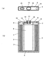
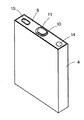
非水電解液の注入後に外装缶の封止を行って、図1に示す構造で、図2に示す外観のリチウムイオン二次電池を作製した。この電池は、缶の上部に内圧が上昇した場合に圧力を下げるための開裂ベントを備えている。 After injecting the non-aqueous electrolyte, the outer can was sealed to produce a lithium ion secondary battery having the structure shown in FIG. 1 and the appearance shown in FIG. This battery includes a cleavage vent for lowering the pressure when the internal pressure rises at the top of the can.
ここで図1および図2に示す電池について説明すると、図1の(a)は平面図、(b)はその部分断面図であって、図1(b)に示すように、正極1と負極2は前記のようにセパレータ3を介して渦巻状に巻回した後、扁平状になるように加圧して扁平状の巻回電極体6として、角筒形の外装缶4に電解液と共に収容されている。ただし、図1では、煩雑化を避けるため、正極1や負極2の作製にあたって使用した集電体としての金属箔や電解液などは図示していない。また、セパレータの各層も区別して示していない。
Here, the battery shown in FIGS. 1 and 2 will be described. FIG. 1A is a plan view, and FIG. 1B is a partial cross-sectional view thereof. As shown in FIG. 2 is spirally wound through the
外装缶6はアルミニウム合金製で電池の外装体を構成するものであり、この外装缶4は正極端子を兼ねている。そして、外装缶4の底部にはPEシートからなる絶縁体5が配置され、正極1、負極2およびセパレータ3からなる扁平状巻回電極体6からは、正極1および負極2のそれぞれ一端に接続された正極リード体7と負極リード体8が引き出されている。また、外装缶4の開口部を封口するアルミニウム合金製の封口用蓋板9にはPP製の絶縁パッキング10を介してステンレス鋼製の端子11が取り付けられ、この端子11には絶縁体12を介してステンレス鋼製のリード板13が取り付けられている。
The
そして、この蓋板9は外装缶4の開口部に挿入され、両者の接合部を溶接することによって、外装缶4の開口部が封口され、電池内部が密閉されている。また、図1の電池では、蓋板9に非水電解液注入口14が設けられており、この非水電解液注入口14には、封止部材が挿入された状態で、例えばレーザー溶接などにより溶接封止されて、電池の密閉性が確保されている(従って、図1および図2の電池では、実際には、非水電解液注入口14は、非水電解液注入口と封止部材であるが、説明を容易にするために、非水電解液注入口14として示している)。更に、蓋板9には、電池の温度が上昇した際に内部のガスを外部に排出する機構として、開裂ベント15が設けられている。
And this
この実施例1の電池では、正極リード体7を蓋板9に直接溶接することによって外装缶5と蓋板9とが正極端子として機能し、負極リード体8をリード板13に溶接し、そのリード板13を介して負極リード体8と端子11とを導通させることによって端子11が負極端子として機能するようになっているが、外装缶4の材質などによっては、その正負が逆になる場合もある。
In the battery of this Example 1, the
図2は前記図1に示す電池の外観を模式的に示す斜視図であり、この図2は前記電池が角形電池であることを示すことを目的として図示されたものであって、この図1では電池を概略的に示しており、電池の構成部材のうち特定のものしか図示していない。また、図1においても、電極群の内周側の部分は断面にしていない。 FIG. 2 is a perspective view schematically showing the external appearance of the battery shown in FIG. 1. FIG. 2 is shown for the purpose of showing that the battery is a square battery. FIG. 1 schematically shows a battery, and only specific members of the battery are shown. Also in FIG. 1, the inner peripheral portion of the electrode group is not cross-sectional.
実施例2〜8
正極の集電体に用いたアルミニウム箔を、表面の濡れ性が表1に示す値のものとし、負極活物質に用いた黒鉛Aと黒鉛Bとの混合比(質量比)を表1に示すようにした以外は、実施例1と同様にしてリチウムイオン二次電池を作製した。
Examples 2-8
The aluminum foil used for the current collector of the positive electrode has the surface wettability as shown in Table 1, and the mixing ratio (mass ratio) of graphite A and graphite B used for the negative electrode active material is shown in Table 1. A lithium ion secondary battery was produced in the same manner as in Example 1 except for the above.
実施例9
実施例1で積層型のセパレータに使用したものと同じPE製微多孔膜セパレータに、多孔質層(II)を形成することなくセパレータとして用いた以外は、実施例1と同様にしてリチウムイオン二次電池を作製した。
Example 9
In the same manner as in Example 1, except that the same microporous membrane separator made of PE as that used for the laminated separator in Example 1 was used as the separator without forming the porous layer (II). A secondary battery was produced.
比較例1
正極の集電体に用いたアルミニウム箔を、表面の濡れ性が表1に示す値のものとし、セパレータを、実施例1で積層型のセパレータの多孔質層(I)に用いたものと同じPE製微多孔膜に変更した以外は、実施例1と同様にしてリチウムイオン二次電池を作製した。
Comparative Example 1
The aluminum foil used for the current collector of the positive electrode has the surface wettability shown in Table 1, and the separator is the same as that used in Example 1 for the porous layer (I) of the multilayer separator. A lithium ion secondary battery was produced in the same manner as in Example 1 except that the microporous film made of PE was used.
<−5℃・10%充電での充電電流測定>
実施例1〜9および比較例1のリチウムイオン二次電池を−5℃の恒温槽内に5時間静置し、その後、各電池について、4.2Vまで1200mA(1.0C)の定電流で充電を行い、4.2Vに達した後は4.2Vで定電圧充電を行い、充電深度(規格容量に対する実際に充電した容量の割合)が10%に達したときの電流値を測定した。これらの結果を表1に併記する。
<Measurement of charge current at -5 ° C and 10% charge>
The lithium ion secondary batteries of Examples 1 to 9 and Comparative Example 1 were allowed to stand in a thermostatic bath at −5 ° C. for 5 hours, and then each battery was subjected to a constant current of 1200 mA (1.0 C) up to 4.2 V. After reaching 4.2V, constant voltage charging was performed at 4.2V, and the current value was measured when the charging depth (the ratio of the actually charged capacity to the standard capacity) reached 10%. These results are also shown in Table 1.
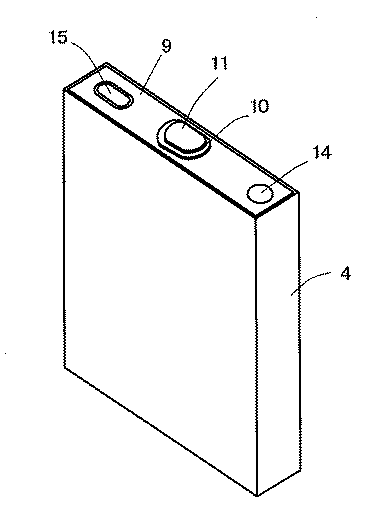
なお、表1には、各電池の負極について、実施例1の電池に係る負極と同様にして測定した負極合剤層表面の算術平均粗さ(Ra)を併記している。 Table 1 also shows the arithmetic average roughness (Ra) of the surface of the negative electrode mixture layer measured for the negative electrode of each battery in the same manner as the negative electrode for the battery of Example 1.
表1に示すように、表面の濡れ性が好適値にあるアルミニウム箔を正極集電体に用いて構成した実施例1〜9のリチウムイオン二次電池は、表面の濡れ性が低いアルミニウム箔を正極集電体に用いた比較例1の電池に比べて、製造時における非水電解液の注液時間が非常に短くなっており、高い生産性を有していることが分かる。 As shown in Table 1, the lithium ion secondary batteries of Examples 1 to 9 configured by using an aluminum foil having a surface wettability at a suitable value as the positive electrode current collector were prepared using an aluminum foil having a low surface wettability. Compared to the battery of Comparative Example 1 used for the positive electrode current collector, it can be seen that the time for injecting the non-aqueous electrolyte at the time of manufacture is very short, and the productivity is high.
1 正極
2 負極
3 セパレータ
1
Claims (5)
前記正極は、集電体であるアルミニウム箔の少なくとも一方の面に、リチウム含有複合酸化物を正極活物質として含む正極合剤層を有しており、
前記正極の集電体を構成するアルミニウム箔は、表面の濡れ性が40mN/m以上であることを特徴とするリチウムイオン二次電池。 A lithium ion secondary battery having a positive electrode, a negative electrode, a non-aqueous electrolyte, and a separator,
The positive electrode has a positive electrode mixture layer containing a lithium-containing composite oxide as a positive electrode active material on at least one surface of an aluminum foil as a current collector,
The aluminum foil constituting the positive electrode current collector has a surface wettability of 40 mN / m or more, and is a lithium ion secondary battery.
The negative electrode mixture layer is, with R-values 0.1 to 0.5 is the peak intensity ratio of 1360 cm -1 to the peak intensity of 1580 cm -1 in the argon ion laser Raman spectrum, the surface spacing d 002 of the 002 plane is 0. The lithium ion secondary battery in any one of Claims 1-4 which contains the graphite which is 338 nm or less as a negative electrode active material.
Priority Applications (1)
| Application Number | Priority Date | Filing Date | Title |
|---|---|---|---|
| JP2010058092A JP2011192543A (en) | 2010-03-15 | 2010-03-15 | Lithium ion secondary battery |
Applications Claiming Priority (1)
| Application Number | Priority Date | Filing Date | Title |
|---|---|---|---|
| JP2010058092A JP2011192543A (en) | 2010-03-15 | 2010-03-15 | Lithium ion secondary battery |
Publications (1)
| Publication Number | Publication Date |
|---|---|
| JP2011192543A true JP2011192543A (en) | 2011-09-29 |
Family
ID=44797227
Family Applications (1)
| Application Number | Title | Priority Date | Filing Date |
|---|---|---|---|
| JP2010058092A Pending JP2011192543A (en) | 2010-03-15 | 2010-03-15 | Lithium ion secondary battery |
Country Status (1)
| Country | Link |
|---|---|
| JP (1) | JP2011192543A (en) |
Cited By (9)
| Publication number | Priority date | Publication date | Assignee | Title |
|---|---|---|---|---|
| WO2013150937A1 (en) * | 2012-04-05 | 2013-10-10 | Necエナジーデバイス株式会社 | Lithium ion secondary cell |
| WO2014003067A1 (en) * | 2012-06-28 | 2014-01-03 | トヨタ自動車株式会社 | Non-aqueous electrolyte secondary battery |
| JP2015053116A (en) * | 2013-09-05 | 2015-03-19 | トヨタ自動車株式会社 | Nonaqueous electrolyte secondary battery |
| JP2016048668A (en) * | 2013-12-17 | 2016-04-07 | 日立マクセル株式会社 | Lithium ion secondary battery |
| JP2016181409A (en) * | 2015-03-24 | 2016-10-13 | 株式会社Gsユアサ | Electricity storage element |
| CN110419128A (en) * | 2017-09-15 | 2019-11-05 | 株式会社Lg化学 | Negative electrode for lithium secondary battery and lithium secondary battery including the same |
| CN111937189A (en) * | 2018-02-06 | 2020-11-13 | 积水化学工业株式会社 | Electrode for lithium ion secondary battery, method for producing the same, and lithium ion secondary battery |
| EP3340343B1 (en) * | 2016-12-20 | 2022-11-23 | Asahi Kasei Kabushiki Kaisha | Separator for power storage device, and laminated body, roll and secondary battery using it |
| EP3931895B1 (en) | 2019-02-25 | 2023-06-07 | Speira GmbH | Aluminium foil for battery electrodes and production method |
-
2010
- 2010-03-15 JP JP2010058092A patent/JP2011192543A/en active Pending
Cited By (13)
| Publication number | Priority date | Publication date | Assignee | Title |
|---|---|---|---|---|
| US10340550B2 (en) | 2012-04-05 | 2019-07-02 | Nec Energy Devices, Ltd. | Lithium ion secondary cell |
| JPWO2013150937A1 (en) * | 2012-04-05 | 2015-12-17 | Necエナジーデバイス株式会社 | Lithium ion secondary battery |
| WO2013150937A1 (en) * | 2012-04-05 | 2013-10-10 | Necエナジーデバイス株式会社 | Lithium ion secondary cell |
| WO2014003067A1 (en) * | 2012-06-28 | 2014-01-03 | トヨタ自動車株式会社 | Non-aqueous electrolyte secondary battery |
| JP2014010989A (en) * | 2012-06-28 | 2014-01-20 | Toyota Motor Corp | Nonaqueous electrolyte secondary battery |
| JP2015053116A (en) * | 2013-09-05 | 2015-03-19 | トヨタ自動車株式会社 | Nonaqueous electrolyte secondary battery |
| JP2016048668A (en) * | 2013-12-17 | 2016-04-07 | 日立マクセル株式会社 | Lithium ion secondary battery |
| JP2016181409A (en) * | 2015-03-24 | 2016-10-13 | 株式会社Gsユアサ | Electricity storage element |
| EP3340343B1 (en) * | 2016-12-20 | 2022-11-23 | Asahi Kasei Kabushiki Kaisha | Separator for power storage device, and laminated body, roll and secondary battery using it |
| CN110419128A (en) * | 2017-09-15 | 2019-11-05 | 株式会社Lg化学 | Negative electrode for lithium secondary battery and lithium secondary battery including the same |
| CN110419128B (en) * | 2017-09-15 | 2022-12-13 | 株式会社Lg新能源 | Negative electrode for lithium secondary battery and lithium secondary battery including the same |
| CN111937189A (en) * | 2018-02-06 | 2020-11-13 | 积水化学工业株式会社 | Electrode for lithium ion secondary battery, method for producing the same, and lithium ion secondary battery |
| EP3931895B1 (en) | 2019-02-25 | 2023-06-07 | Speira GmbH | Aluminium foil for battery electrodes and production method |
Similar Documents
| Publication | Publication Date | Title |
|---|---|---|
| JP5042400B2 (en) | Non-aqueous secondary battery | |
| JP4868556B2 (en) | Lithium secondary battery | |
| JP6499427B2 (en) | Lithium ion secondary battery | |
| JP6253411B2 (en) | Lithium secondary battery | |
| JP2011192543A (en) | Lithium ion secondary battery | |
| JP2011243558A (en) | Lithium secondary battery positive electrode and lithium secondary battery | |
| JP2008198596A (en) | Positive electrode for lithium secondary battery, method for producing the same, and lithium secondary battery | |
| JP5157222B2 (en) | Electrode and electrochemical device | |
| JP2011154936A (en) | Separator for battery and lithium secondary battery | |
| JP4840302B2 (en) | Separator and battery using the same | |
| JP2011154967A (en) | Separator for battery, and lithium ion secondary battery using it | |
| JP5566825B2 (en) | Lithium secondary battery | |
| JP2010027547A (en) | Separator for electrochemical element and lithium-ion battery using the same | |
| JP2017016944A (en) | Lithium ion secondary battery | |
| JP2013191345A (en) | Lithium secondary battery and manufacturing method thereof | |
| JP5658122B2 (en) | Lithium secondary battery | |
| JP2013030398A (en) | Negative electrode material, method for manufacturing the same, negative electrode for nonaqueous electrolyte secondary battery, and nonaqueous electrolyte secondary battery | |
| JP2010027551A (en) | Separator for electrochemical element and lithium-ion battery using the same | |
| JP2010027548A (en) | Separator for electrochemical element and lithium-ion battery using the same | |
| JP2019220357A (en) | Electrode for lithium ion secondary battery, and lithium ion secondary battery | |
| JP5785653B2 (en) | Lithium secondary battery | |
| JP2010027552A (en) | Separator for electrochemical element and lithium-ion battery using the same | |
| JP2010027550A (en) | Separator for electrochemical element and lithium-ion battery using the same | |
| JP2008234852A (en) | Non-aqueous electrolyte secondary battery |