JP2011227770A - Communication confirmation device, communication confirmation method and program - Google Patents

Communication confirmation device, communication confirmation method and program Download PDF

Info

Publication number
JP2011227770A
JP2011227770A JP2010098106A JP2010098106A JP2011227770A JP 2011227770 A JP2011227770 A JP 2011227770A JP 2010098106 A JP2010098106 A JP 2010098106A JP 2010098106 A JP2010098106 A JP 2010098106A JP 2011227770 A JP2011227770 A JP 2011227770A
Authority
JP
Japan
Prior art keywords
error
connection request
monitoring target
communication
monitored
Prior art date
Legal status (The legal status is an assumption and is not a legal conclusion. Google has not performed a legal analysis and makes no representation as to the accuracy of the status listed.)
Granted
Application number
JP2010098106A
Other languages
Japanese (ja)
Other versions
JP5471765B2 (en
Inventor
Tomohiro Ikeda
知弘 池田
Koichi Wakimoto
浩一 脇本
Hiroyuki Tanaka
博幸 田中
Yoshihiro Takeuchi
恵裕 竹内
Yukio Kise
幸雄 木瀬
Toru Natsumi
徹 夏見
Current Assignee (The listed assignees may be inaccurate. Google has not performed a legal analysis and makes no representation or warranty as to the accuracy of the list.)
Fujitsu Ltd
Original Assignee
Fujitsu Ltd
Priority date (The priority date is an assumption and is not a legal conclusion. Google has not performed a legal analysis and makes no representation as to the accuracy of the date listed.)
Filing date
Publication date
Application filed by Fujitsu Ltd filed Critical Fujitsu Ltd
Priority to JP2010098106A priority Critical patent/JP5471765B2/en
Publication of JP2011227770A publication Critical patent/JP2011227770A/en
Application granted granted Critical
Publication of JP5471765B2 publication Critical patent/JP5471765B2/en
Expired - Fee Related legal-status Critical Current
Anticipated expiration legal-status Critical

Links

Images

Landscapes

  • Debugging And Monitoring (AREA)
  • Computer And Data Communications (AREA)

Abstract

【課題】被監視装置に発生したエラーの重要度が被監視装置の通信状態によって決まる場合に、その通信状態を精度よく確認できる通信確認装置、通信確認方法及びプログラムを提供する。
【解決手段】監視対象装置10が接続された上位サーバ装置20と接続してあり、上位サーバ装置20へ接続要求を送信し、接続要求を受信した上位サーバ装置20が監視対象装置10に送信させた応答を受信することで、監視対象装置10の通信状態を確認する情報処理装置1において、監視対象装置10にエラーが発生した場合、接続要求を上位サーバ装置20へ第1及び第2送信に分けて二回送信し、第2送信で送信した接続要求に対する応答を受信したか否かにより、監視対象装置10の通信状態を確認する。
【選択図】図1
A communication confirmation device, a communication confirmation method, and a program capable of accurately confirming a communication state when the importance of an error that has occurred in the monitored device is determined by the communication state of the monitored device.
A monitoring target device is connected to a higher-level server device to which it is connected, transmits a connection request to the higher-level server device, and causes the higher-level server device that receives the connection request to transmit to the monitoring target device. In the information processing apparatus 1 that confirms the communication state of the monitoring target device 10 by receiving the received response, if an error occurs in the monitoring target device 10, the connection request is sent to the upper server device 20 in the first and second transmissions. The communication state of the monitoring target device 10 is confirmed based on whether or not a response to the connection request transmitted in the second transmission has been received.
[Selection] Figure 1

Description

本発明は、複数の被監視装置が接続された外部装置と接続してあり、外部装置へ接続要求信号を送信し、接続要求信号を受信した外部装置が被監視装置に送信させた応答信号を受信することで、被監視装置の通信状態を確認する通信確認装置、通信確認方法及びプログラムに関する。   The present invention is connected to an external device to which a plurality of monitored devices are connected, transmits a connection request signal to the external device, and transmits a response signal transmitted to the monitored device by the external device that has received the connection request signal. The present invention relates to a communication confirmation device, a communication confirmation method, and a program for confirming a communication state of a monitored device by receiving the information.

ネットワーク機器に障害が発生した場合、早急に障害を復旧するための保守システムがある。例えば、特許文献1は、ネットワーク機器の障害発生を自動的にサービスセンタで検知し、障害に応じた保守手順を自動的に編集して、保守手順を映像で示す保守画面を、ネットワーク機器のユーザに送信する保守システムが開示されている。特許文献1に記載の保守システムにより、ネットワーク機器のユーザは、コンピュータに詳しくない場合であっても、保守画面を見ながらエラー復旧作業を簡単に行うことができる。   There is a maintenance system for quickly recovering from a failure in a network device. For example, in Patent Document 1, a service center automatically detects the occurrence of a failure in a network device, automatically edits a maintenance procedure according to the failure, and displays a maintenance screen with a video image of the maintenance procedure. A maintenance system is disclosed for transmission. With the maintenance system described in Patent Document 1, even if the user of the network device is not familiar with the computer, the user can easily perform error recovery work while looking at the maintenance screen.

特開2004−086719号公報JP 2004-086719 A

しかしながら、特許文献1に記載の保守システムでは、障害の深刻度に関係なく、障害がユーザに通知されるため、発生した障害を早急に解決する必要があるかどうかを、ユーザには判断できない場合がある。   However, in the maintenance system described in Patent Document 1, since the failure is notified to the user regardless of the severity of the failure, the user cannot determine whether the occurring failure needs to be resolved immediately. There is.

本発明はかかる事情に鑑みてなされたものであり、その目的とするところは、被監視装置に発生したエラーの重要度が被監視装置の通信状態によって決まる場合に、その通信状態を精度よく確認できる通信確認装置、通信確認方法及びプログラムを提供することにある。   The present invention has been made in view of such circumstances, and an object of the present invention is to accurately check the communication status when the importance of an error occurring in the monitored device is determined by the communication status of the monitored device. An object of the present invention is to provide a communication confirmation device, a communication confirmation method, and a program.

本願に開示する通信確認装置は、複数の被監視装置が接続され、接続要求信号を前記被監視装置に分配する外部装置に、接続要求信号を送信することで、前記被監視装置の通信状態を確認する通信確認装置において、前記被監視装置にエラーが発生したことを検知する検知部と、前記被監視装置、及び該被監視装置が接続される外部装置の接続先を記憶する通信先記憶部と、該検知部がエラーを検知した場合、前記通信先記憶部に記憶した接続先に基づいて接続要求信号を前記外部装置へ二回送信する送信部と、該送信部が二回目に送信した接続要求信号に対する応答信号を受信したか否かを判定する判定部とを備える。   The communication confirmation device disclosed in the present application transmits a connection request signal to an external device to which a plurality of monitored devices are connected and distributes a connection request signal to the monitored device, thereby changing the communication state of the monitored device. In the communication confirmation device to be confirmed, a detection unit that detects that an error has occurred in the monitored device, and a communication destination storage unit that stores connection destinations of the monitored device and an external device to which the monitored device is connected When the detection unit detects an error, the transmission unit transmits the connection request signal to the external device twice based on the connection destination stored in the communication destination storage unit, and the transmission unit transmits the second time A determination unit that determines whether or not a response signal to the connection request signal has been received.

本願に開示する通信確認装置の一観点によれば、エラーが発生した被監視装置の通信状態を、より精度よく確認することができる。また、通信異常が被監視装置の運用に問題を引き起こす場合、確実に通信状態を把握することで、専門の担当者へ復旧依頼を早急に通知することができ、短時間でのエラーの復旧が可能となる。   According to one aspect of the communication confirmation apparatus disclosed in the present application, the communication state of the monitored apparatus in which an error has occurred can be confirmed more accurately. In addition, if a communication error causes a problem in the operation of the monitored device, it is possible to quickly notify the specialist in charge of a recovery request by ascertaining the communication status reliably, and error recovery in a short time. It becomes possible.

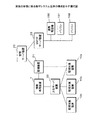
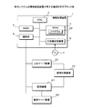
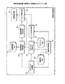
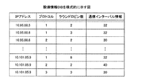
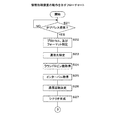
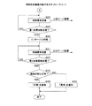
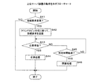
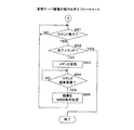
実施の形態に係る保守システム全体の構成を示す模式図である。It is a schematic diagram which shows the structure of the whole maintenance system which concerns on embodiment. 保守システムの情報処理装置が有する構成を示すブロック図である。It is a block diagram which shows the structure which the information processing apparatus of a maintenance system has. 情報処理装置で実現される機能を示すブロック図である。It is a block diagram which shows the function implement | achieved with information processing apparatus. プロトコルDBを模式的に示す図である。It is a figure which shows protocol DB typically. 通信先DBを模式的に示す図である。It is a figure which shows communication destination DB typically. 設備情報DBを模式的に示す図である。It is a figure which shows equipment information DB typically. SIPを利用する場合に、シナリオ生成部が生成するシナリオの一例を示す図である。It is a figure which shows an example of the scenario which a scenario production | generation part produces | generates when using SIP. HTTPを利用する場合に、シナリオ生成部が生成するシナリオの一例を示す図である。It is a figure which shows an example of the scenario which a scenario production | generation part produces | generates when using HTTP. SMTPを利用する場合に、シナリオ生成部が生成するシナリオの一例を示す図である。It is a figure which shows an example of the scenario which a scenario production | generation part produces | generates when using SMTP. 管理サーバ装置で実現される機能を示すブロック図である。It is a block diagram which shows the function implement | achieved by the management server apparatus. 重要度を決定する方法を説明するための模式図である。It is a schematic diagram for demonstrating the method to determine importance. 携帯電話機でエラー情報を確認する場合の模式図である。It is a schematic diagram when confirming error information with a mobile phone. 監視装置の動作を示すフローチャートである。It is a flowchart which shows operation | movement of a monitoring apparatus. 監視装置の動作を示すフローチャートである。It is a flowchart which shows operation | movement of a monitoring apparatus. 情報処理装置の動作を示すフローチャートである。It is a flowchart which shows operation | movement of information processing apparatus. 情報処理装置の動作を示すフローチャートである。It is a flowchart which shows operation | movement of information processing apparatus. 上位サーバ装置の動作を示すフローチャートである。It is a flowchart which shows operation | movement of a high-order server apparatus. 管理サーバ装置の動作を示すフローチャートである。It is a flowchart which shows operation | movement of a management server apparatus. 管理サーバ装置の動作を示すフローチャートである。It is a flowchart which shows operation | movement of a management server apparatus.

以下に、本願に開示する通信確認装置、通信確認方法及びプログラムについて、好適な実施の形態を、図面を参照しつつ詳述する。以下に説明する実施の形態では、本願に開示する通信確認装置を備える保守システムについて説明する。   Hereinafter, preferred embodiments of a communication confirmation device, a communication confirmation method, and a program disclosed in the present application will be described in detail with reference to the drawings. In the embodiments described below, a maintenance system including a communication confirmation device disclosed in the present application will be described.

本実施の形態に係る保守システムは、呼制御サーバ装置、WEBサーバ装置又はSimple Mail Transfer Protocol(SMTP)サーバ装置等のネットワーク装置に発生するエラーを監視し、発生したエラーの重要度に応じて、保守担当者へエラーを通知するシステムである。保守担当者への通知は、保守担当者が所有する携帯電話機又はパーソナルコンピュータ(以下、パソコンという)等へメールにて行われる。以下の説明では、監視するネットワーク装置を、監視対象装置という。   The maintenance system according to the present embodiment monitors an error that occurs in a network device such as a call control server device, a WEB server device, or a Simple Mail Transfer Protocol (SMTP) server device, and according to the importance of the generated error, This system notifies the maintenance staff of errors. The notification to the maintenance staff is made by e-mail to a mobile phone or a personal computer (hereinafter referred to as a personal computer) owned by the maintenance staff. In the following description, the network device to be monitored is referred to as a monitoring target device.

図1は、実施の形態に係る保守システム全体の構成を示す模式図である。保守システムは、監視対象装置(被監視装置)10a,10b,10cを監視するための情報処理装置(通信確認装置)1、上位サーバ装置(外部装置)20、監視装置21及び管理サーバ装置22等を備えている。監視対象装置10a,10b,10cは、同じ構成及び機能を有し、かつ、同じ動作を行う装置であって、同じグループとして上位サーバ装置20に接続されている。以下の説明では、監視対象装置10a,10b,10cをまとめて監視対象装置10という。   FIG. 1 is a schematic diagram illustrating a configuration of the entire maintenance system according to the embodiment. The maintenance system includes an information processing device (communication confirmation device) 1, a host server device (external device) 20, a monitoring device 21, a management server device 22, and the like for monitoring the devices to be monitored (monitored devices) 10a, 10b, and 10c. It has. The monitoring target devices 10a, 10b, and 10c are devices that have the same configuration and function and perform the same operation, and are connected to the upper server device 20 as the same group. In the following description, the monitoring target devices 10a, 10b, and 10c are collectively referred to as the monitoring target device 10.

上位サーバ装置20は、例えば、Session Initiation Protocol(SIP)サーバ装置、Hypertext Transfer Protocol(HTTP)を利用するWEBサーバ装置、又はSMTPサーバ装置等である。上位サーバ装置20は、後述の情報処理装置1から接続要求を受信した場合、自身に接続されている監視対象装置10と情報処理装置1とを接続する。例えば、上位サーバ装置20がSIPサーバ装置の場合、上位サーバ装置20は、SIPを利用して、情報処理装置1及び監視対象装置10が有する電話機(図示せず)を、電話番号をもとに接続し、又は切断する呼制御を行う。また、WEBサーバ装置の場合、上位サーバ装置20は、HTTPを利用して、情報処理装置1及び監視対象装置10間で、画像等のコンテンツの送受を行う。SMTPサーバ装置の場合、上位サーバ装置20は、SMTPを利用して、情報処理装置1及び監視対象装置10間でメールの送受を行う。なお、上位サーバ装置20は、複数あってもよく、複数の場合には、SIPサーバ装置及びWEBサーバ装置等が混在していてもよい。   The host server device 20 is, for example, a Session Initiation Protocol (SIP) server device, a WEB server device using a Hypertext Transfer Protocol (HTTP), or an SMTP server device. When the upper server apparatus 20 receives a connection request from the information processing apparatus 1 to be described later, the upper server apparatus 20 connects the monitoring target apparatus 10 and the information processing apparatus 1 connected to itself. For example, when the higher-level server device 20 is a SIP server device, the higher-level server device 20 uses SIP to call a telephone (not shown) of the information processing device 1 and the monitoring target device 10 based on the telephone number. Call control to connect or disconnect. In the case of a WEB server device, the upper server device 20 transmits and receives content such as an image between the information processing device 1 and the monitoring target device 10 using HTTP. In the case of an SMTP server device, the upper server device 20 transmits and receives mail between the information processing device 1 and the monitoring target device 10 using SMTP. Note that there may be a plurality of upper server devices 20, and in the case of a plurality of servers, a SIP server device and a WEB server device may be mixed.

本実施の形態では、上位サーバ装置20は、ラウンドロビン方式に従って、接続する監視対象装置10を選択し、通信を行う。例えば、上位サーバ装置20は、最初に接続要求を受信したとき、監視対象装置10aとの通信を行い、次に接続要求を受信したときには、監視対象装置10bとの通信を行う。続いて、接続要求を受信したときには、上位サーバ装置20は、監視対象装置10cとの通信を行う。また、上位サーバ装置20は、ラウンドロビン方式に従って監視対象装置10と通信した場合、監視対象装置10の一つが故障と判断したとき、その監視対象装置10に対して閉塞処理を実行する。閉塞処理を実行した場合、上位サーバ装置20は、接続要求を受信しても、閉塞処理を実行した監視対象装置10に対しては、通信をしなくなる。   In the present embodiment, the host server device 20 selects the monitoring target device 10 to be connected and performs communication according to the round robin method. For example, the host server device 20 communicates with the monitoring target device 10a when the connection request is first received, and communicates with the monitoring target device 10b when the connection request is received next. Subsequently, when a connection request is received, the upper server device 20 communicates with the monitoring target device 10c. In addition, when the upper server apparatus 20 communicates with the monitoring target apparatus 10 according to the round robin method, when it is determined that one of the monitoring target apparatuses 10 is out of order, the upper level server apparatus 20 executes a blocking process on the monitoring target apparatus 10. When the blocking process is executed, the upper server apparatus 20 does not communicate with the monitoring target apparatus 10 that has executed the blocking process even if it receives a connection request.

監視対象装置10は、Local Area Network(LAN)又はWide Area Network(WAN)等の通信網を介して監視装置21と接続している。監視装置21は、監視対象装置10にエラーが発生したことを検知する装置である。なお、図中は、監視対象装置10aのみが監視装置21と接続しているが、監視対象装置10b,10cも監視装置21と接続している。監視対象装置10は、監視装置21に対して、Simple Network Management Protocol(SNMP)トラップを送信する。監視装置21は、監視対象装置10から送信されたSNMPトラップに基づいて、監視対象装置10にエラーが発生したことを検知する。以下では、監視対象装置10aにエラーが発生し、監視対象装置10b,10cは正常に動作するものとして説明する。   The monitoring target device 10 is connected to the monitoring device 21 via a communication network such as a local area network (LAN) or a wide area network (WAN). The monitoring device 21 is a device that detects that an error has occurred in the monitoring target device 10. In the figure, only the monitoring target device 10 a is connected to the monitoring device 21, but the monitoring target devices 10 b and 10 c are also connected to the monitoring device 21. The monitoring target device 10 transmits a Simple Network Management Protocol (SNMP) trap to the monitoring device 21. The monitoring device 21 detects that an error has occurred in the monitoring target device 10 based on the SNMP trap transmitted from the monitoring target device 10. In the following description, it is assumed that an error occurs in the monitoring target device 10a and the monitoring target devices 10b and 10c operate normally.

監視装置21は、検知したエラーに対応するエラー番号を特定し、エラー番号を監視対象装置10aへ通知する。エラー番号が通知された監視対象装置10aは、エラー番号をもとに、発生したエラーの解析に必要なログを抽出して、エラーログとして監視装置21へ送信する。エラーログには、監視対象装置10aが状態確認コマンドを投入することで得られる自身の動作状態を含む。   The monitoring device 21 identifies an error number corresponding to the detected error and notifies the monitoring target device 10a of the error number. The monitoring target device 10a notified of the error number extracts a log necessary for analyzing the error that has occurred based on the error number, and transmits it to the monitoring device 21 as an error log. The error log includes its own operation state obtained by the monitoring target device 10a issuing a state confirmation command.

上位サーバ装置20及び監視装置21は、通信網を介して情報処理装置1と接続している。情報処理装置1は、監視対象装置10aに発生したエラーの重要度を決定するために、監視対象装置10aの通信状態を確認するための装置である。エラーの重要度は、後述の管理サーバ装置22で決定され、監視対象装置10aを含む他の監視対象装置10b,10cとの通信ができない場合には、高く決定される。情報処理装置1は、監視装置21から、エラーが発生した監視対象装置10aを特定する情報として、Internet Protocol(IP)アドレスを受信する。情報処理装置1は、そのIPアドレスから監視対象装置10a、及び、監視対象装置10aの運用に必要なプロトコルを特定する。情報処理装置1は、特定したプロトコルにより、特定した監視対象装置10aの通信状態の確認を上位サーバ装置20を介して行う。より具体的には、情報処理装置1は、監視対象装置10aを含めて、上位サーバ装置20に接続している監視対象装置10b,10cの通信状態を確認する。通信状態は、上位サーバ装置20に送信した接続要求に対して、監視対象装置10から応答を受信したか否かにより確認される。そして、情報処理装置1は、確認結果を監視装置21へ送信する。   The host server device 20 and the monitoring device 21 are connected to the information processing device 1 via a communication network. The information processing device 1 is a device for confirming the communication state of the monitoring target device 10a in order to determine the importance of the error that has occurred in the monitoring target device 10a. The importance of the error is determined by the management server device 22 described later, and is determined to be high when communication with the other monitoring target devices 10b and 10c including the monitoring target device 10a is impossible. The information processing apparatus 1 receives an Internet Protocol (IP) address from the monitoring apparatus 21 as information for specifying the monitoring target apparatus 10a in which an error has occurred. The information processing apparatus 1 identifies the monitoring target apparatus 10a and the protocol necessary for the operation of the monitoring target apparatus 10a from the IP address. The information processing apparatus 1 confirms the communication state of the specified monitoring target apparatus 10a via the higher-level server apparatus 20 using the specified protocol. More specifically, the information processing apparatus 1 checks the communication status of the monitoring target devices 10b and 10c connected to the higher-level server device 20 including the monitoring target device 10a. The communication state is confirmed by whether or not a response has been received from the monitoring target device 10 in response to the connection request transmitted to the upper server device 20. Then, the information processing device 1 transmits the confirmation result to the monitoring device 21.

監視装置21は、通信網を介して管理サーバ装置22と接続している。管理サーバ装置22は、発生したエラーを管理し、エラーの重要度を決定する装置である。管理サーバ装置22は、上述したエラー番号、通信状態の確認結果、及びエラーログを監視装置21から受信する。管理サーバ装置22は、受信したエラー番号、及びエラーログをもとに、エラー名、及びエラー発生時刻等のエラー情報をWEB表示可能にする。管理サーバ装置22は、SMTPサーバ装置23と接続しており、WEB表示可能にしたエラー情報へのリンクを含めたメールを、保守担当者が所有する携帯電話機100又はパソコン101,102等へ送信する。これにより、保守担当者は、携帯電話機100又はパソコン101,102等から管理サーバ装置22へアクセスすることで、エラー情報を確認することが可能となる。なお、本実施の形態では、保守担当者は、システムを運用する運用者、及び、システムに発生したエラーを解析する解析者を含む。そして、携帯電話機100及びパソコン101は解析者が所有し、パソコン102は運用者が所有するものとする。   The monitoring device 21 is connected to the management server device 22 via a communication network. The management server device 22 is a device that manages an error that has occurred and determines the importance of the error. The management server device 22 receives the error number, the communication state confirmation result, and the error log described above from the monitoring device 21. Based on the received error number and error log, the management server device 22 enables error information such as an error name and an error occurrence time to be displayed on the web. The management server device 22 is connected to the SMTP server device 23, and transmits a mail including a link to error information that can be displayed on the web to the mobile phone 100 or the personal computers 101, 102 owned by the maintenance staff. . As a result, the maintenance staff can check the error information by accessing the management server device 22 from the mobile phone 100 or the personal computers 101, 102 or the like. In this embodiment, the maintenance staff includes an operator who operates the system and an analyst who analyzes an error that has occurred in the system. The mobile phone 100 and the personal computer 101 are owned by an analyst, and the personal computer 102 is owned by an operator.

管理サーバ装置22は、受信したエラー番号、及び通信状態の確認結果から、監視対象装置10aに発生したエラーの重要度を決定し、重要度に応じて、メール送信先を決定する。例えば、エラーが発生した監視対象装置10aの通信状態が異常の場合には、管理サーバ装置22は、エラーの重要度を高く決定し、メール送信先を携帯電話機100に決定する。携帯電話機100は、解析者が常時携帯している可能性が高いため、メールを携帯電話機100へ送信することで、早急なエラー対策を行うことができる。監視対象装置10aの通信状態が正常であるため早急なエラー対策は必要ないが、解析者にしか解決できないエラーの場合、管理サーバ装置22は、エラーの重要度を低く決定し、メール送信先を解析者のパソコン101に決定する。また、運用者にでも解決できるエラーの場合、管理サーバ装置22は、エラーの重要度を低く決定し、メール送信先を運用者のパソコン102に決定する。   The management server device 22 determines the importance of the error that has occurred in the monitoring target device 10a from the received error number and the communication status confirmation result, and determines the mail transmission destination according to the importance. For example, when the communication state of the monitoring target device 10a in which an error has occurred is abnormal, the management server device 22 determines the importance of the error to be high and determines the mail transmission destination to the mobile phone 100. Since the mobile phone 100 is likely to be always carried by the analyst, it is possible to take immediate error countermeasures by sending an email to the mobile phone 100. Since the communication state of the monitoring target device 10a is normal, immediate error countermeasures are not necessary. However, in the case of an error that can be solved only by an analyst, the management server device 22 determines the importance of the error to be low and determines the mail transmission destination. The analyzer PC 101 is determined. In the case of an error that can be solved even by the operator, the management server device 22 determines the importance of the error to be low, and determines the mail transmission destination to the operator's personal computer 102.

なお、図1では、3つの監視対象装置を示しているが、監視対象装置の数はこれに限定されない。また、図1では、保守システムは、一つの上位サーバ装置20を介して監視対象装置10を監視する構成としているが、複数の上位サーバ装置を有し、それぞれの上位サーバ装置に接続される監視対象装置を監視する構成としてもよい。さらに、保守システムを構成する各装置は、キーボード及びマウス等を備えるパソコンで実現するようにしてもよい。   Although FIG. 1 shows three monitoring target devices, the number of monitoring target devices is not limited to this. In FIG. 1, the maintenance system is configured to monitor the monitoring target device 10 via one upper server device 20. However, the maintenance system has a plurality of upper server devices and is connected to each upper server device. The configuration may be such that the target device is monitored. Furthermore, each device constituting the maintenance system may be realized by a personal computer including a keyboard and a mouse.

以下、保守システムの各装置の具体的な構成及び動作について説明する。   Hereinafter, a specific configuration and operation of each device of the maintenance system will be described.

図2は、保守システムの情報処理装置1が有する構成を示すブロック図である。情報処理装置1は、Central Processing Unit(CPU)2、Read Only Memory(ROM)3、Random Access Memory(RAM)4、大容量記憶装置5、及び、通信網を介して、上位サーバ装置20及び監視装置21等との通信を可能にする通信部6等のハードウェア各部を備える。これらのハードウェア各部はバスを介して相互に接続されている。なお、図2では省略しているが、監視対象装置10、上位サーバ装置20、監視装置21及び管理サーバ装置22は、情報処理装置1と同様に、CPU、ROM、RAM、大容量記憶装置、及び通信部等のハードウェア各部等を備えている。   FIG. 2 is a block diagram illustrating a configuration of the information processing apparatus 1 of the maintenance system. The information processing apparatus 1 includes a central processing unit (CPU) 2, a read only memory (ROM) 3, a random access memory (RAM) 4, a large-capacity storage device 5, and a host server device 20 and a monitor via a communication network. Each hardware unit such as the communication unit 6 that enables communication with the device 21 and the like is provided. These hardware units are connected to each other via a bus. Although omitted in FIG. 2, the monitoring target device 10, the upper server device 20, the monitoring device 21, and the management server device 22 are similar to the information processing device 1, in that a CPU, a ROM, a RAM, a mass storage device, And each hardware part such as a communication part.

CPU2は、ROM3又は大容量記憶装置5に予め格納されているプログラムを適宜RAM4に読み出して実行すると共に、上述したハードウェア各部の動作を制御する。ROM3は、情報処理装置1に必要な動作をさせるためのプログラム3aを予め格納している。RAM4は、例えばStatic RAM(SRAM)、Dynamic RAM(DRAM)、フラッシュメモリ等である。RAM4は、CPU2による制御プログラムの実行時に発生する種々のデータを一時的に記憶する。   The CPU 2 reads out the program stored in advance in the ROM 3 or the large-capacity storage device 5 to the RAM 4 as appropriate and executes it, and also controls the operation of each part of the hardware described above. The ROM 3 stores in advance a program 3a for causing the information processing apparatus 1 to perform a necessary operation. The RAM 4 is, for example, a static RAM (SRAM), a dynamic RAM (DRAM), a flash memory, or the like. The RAM 4 temporarily stores various data generated when the control program is executed by the CPU 2.

大容量記憶装置5は、例えばハードディスクドライブであって、後述する必要なデータベース(DB)を記憶している。なお、ROM3が記憶するプログラム3aは、大容量記憶装置5に記憶されていてもよい。また、プログラム3aは、Compact Disc-ROM(CD−ROM)、Digital Versatile Disc-ROM(DVD−ROM)、又はMagneto-Optical disk(MO)等の記録媒体7により大容量記憶装置5にインストールし、又はネットワークからダウンロードして使用する形態でもよい。   The mass storage device 5 is, for example, a hard disk drive, and stores a necessary database (DB) to be described later. Note that the program 3 a stored in the ROM 3 may be stored in the mass storage device 5. The program 3a is installed in the mass storage device 5 by a recording medium 7 such as a Compact Disc-ROM (CD-ROM), a Digital Versatile Disc-ROM (DVD-ROM), or a Magneto-Optical disk (MO). Alternatively, it may be downloaded from a network and used.

次に、CPU2が上述のROM3に格納されているプログラム3aを実行することで、情報処理装置1で実現される機能について説明する。   Next, functions realized by the information processing apparatus 1 when the CPU 2 executes the program 3a stored in the ROM 3 described above will be described.

図3は、情報処理装置1で実現される機能を示すブロック図である。情報処理装置1は、IPアドレス受信部31、プロトコル特定部32、通信先特定部33、設備情報取得部34、通信回数決定部35、シナリオ生成部36、シナリオ実行部37、及び結果通知部38等の機能を備えている。また、情報処理装置1は、プロトコルDB41、通信先DB(通信先記憶部)42及び設備情報DB(数記憶部)43等を備えている。   FIG. 3 is a block diagram illustrating functions realized by the information processing apparatus 1. The information processing apparatus 1 includes an IP address receiving unit 31, a protocol specifying unit 32, a communication destination specifying unit 33, a facility information acquiring unit 34, a communication count determining unit 35, a scenario generating unit 36, a scenario executing unit 37, and a result notifying unit 38. Etc. are provided. In addition, the information processing apparatus 1 includes a protocol DB 41, a communication destination DB (communication destination storage unit) 42, a facility information DB (number storage unit) 43, and the like.

IPアドレス受信部31(検知部)は、監視装置21からIPアドレスを受信する。監視装置21は、監視対象装置10それぞれからSNMPトラップを受信し、SNMPトラップに基づいて、監視対象装置10aにエラーが発生したことを検知する。このとき、監視装置21は、監視対象装置10aのIPアドレスを情報処理装置1へ送信する。IPアドレス受信部31は、そのIPアドレスを受信する。すなわち、IPアドレス受信部31がIPアドレスを受信することで、情報処理装置1は、エラーを検知する。   The IP address receiving unit 31 (detection unit) receives an IP address from the monitoring device 21. The monitoring device 21 receives an SNMP trap from each of the monitoring target devices 10, and detects that an error has occurred in the monitoring target device 10a based on the SNMP trap. At this time, the monitoring device 21 transmits the IP address of the monitoring target device 10 a to the information processing device 1. The IP address receiving unit 31 receives the IP address. That is, when the IP address receiving unit 31 receives an IP address, the information processing apparatus 1 detects an error.

プロトコル特定部32は、IPアドレス受信部31が受信したIPアドレスに基づいて、エラーが発生した監視対象装置10aの運用に必要なプロトコル、及びそのプロトコルのフォーマットを特定する。プロトコルのフォーマットは、予め情報処理装置1の大容量記憶装置5に複数パターンが格納されている。プロトコル特定部32は、大容量記憶装置5に格納されているプロトコルDB41から、プロトコル及びフォーマットを特定する。   Based on the IP address received by the IP address receiving unit 31, the protocol specifying unit 32 specifies a protocol necessary for operation of the monitored apparatus 10a in which an error has occurred and the format of the protocol. As for the protocol format, a plurality of patterns are stored in the mass storage device 5 of the information processing apparatus 1 in advance. The protocol specifying unit 32 specifies the protocol and format from the protocol DB 41 stored in the mass storage device 5.

図4は、プロトコルDB41を模式的に示す図である。プロトコルDB41は、IPアドレス欄、SIP欄、HTTP欄、及びSMTP欄等を有している。IPアドレス欄には、監視対象装置10のIPアドレスが格納される。SIP欄には、IPアドレスに対応する監視対象装置10が利用するSIPの情報を格納している。例えば、SIP欄に「1」が格納されている場合、対応する監視対象装置10は、フォーマット番号が「1」のプロトコルを用いることを示す。SIP欄に「0」が格納されている場合、対応する監視対象装置10は、SIPを利用しないことを示す。同様に、HTTP欄及びSMTP欄には、IPアドレスに対応する監視対象装置10が利用するHTTP及びSMTPの情報を格納している。なお、プロトコルDB41は、SIP、HTTP及びSMTP以外のプロトコル情報を格納していてもよい。   FIG. 4 is a diagram schematically showing the protocol DB 41. The protocol DB 41 has an IP address column, a SIP column, an HTTP column, an SMTP column, and the like. In the IP address column, the IP address of the monitoring target device 10 is stored. The SIP column stores information on SIP used by the monitoring target device 10 corresponding to the IP address. For example, when “1” is stored in the SIP column, it indicates that the corresponding monitoring target apparatus 10 uses the protocol whose format number is “1”. When “0” is stored in the SIP column, it indicates that the corresponding monitoring target device 10 does not use SIP. Similarly, HTTP and SMTP information used by the monitoring target device 10 corresponding to the IP address is stored in the HTTP column and the SMTP column. The protocol DB 41 may store protocol information other than SIP, HTTP, and SMTP.

通信先特定部33は、IPアドレス受信部31が受信したIPアドレス、及びプロトコル特定部32が特定したプロトコルに基づいて、通信先を特定する。通信先とは、エラーが発生した監視対象装置10aと通信するためにアクセスする宛先である。例えば、監視対象装置10aがSIPを利用する場合には、通信先は、上位サーバ装置20の電話番号となり、HTTPを利用する場合には、上位サーバ装置20のUniform Resource Locator(URL)となる。また、SMTPを利用する場合には、通信先は、上位サーバ装置20のメールアドレスとなる。通信先特定部33は、大容量記憶装置5に格納されている通信先DB42から、通信先を特定する。   The communication destination specifying unit 33 specifies a communication destination based on the IP address received by the IP address receiving unit 31 and the protocol specified by the protocol specifying unit 32. The communication destination is a destination accessed to communicate with the monitoring target device 10a in which an error has occurred. For example, when the monitoring target device 10a uses SIP, the communication destination is the telephone number of the upper server device 20, and when using HTTP, it is the Uniform Resource Locator (URL) of the upper server device 20. Further, when using SMTP, the communication destination is the mail address of the host server device 20. The communication destination specifying unit 33 specifies a communication destination from the communication destination DB 42 stored in the mass storage device 5.

図5は、通信先DB42を模式的に示す図である。通信先DB42は、IPアドレス欄、プロトコル欄、電話番号欄、URL欄及びメールアドレス欄等を有している。IPアドレス欄には、監視対象装置10のIPアドレスが格納される。プロトコル欄には、監視対象装置10が利用するプロトコルが格納される。例えば、プロトコル欄に「1」が格納された場合、対応する監視対象装置10は、SIPを利用し、「2」が格納された場合、HTTPを利用することを示し、「3」が格納された場合、SMTPを利用することを示している。電話番号欄には、対応する監視対象装置10の上位サーバ装置20が有する電話番号が格納される。URL欄には、対応する監視対象装置10の上位サーバ装置20へのパス名が格納される。メールアドレス欄には、対応する監視対象装置10の上位サーバ装置20が有するメールアドレスが格納される。なお、該当する情報がない場合には、各欄には「null」が格納される。例えば、IPアドレス受信部31が「10.95.88.6」のIPアドレスを受信し、プロトコル特定部32がSIPのプロトコルを特定した場合、通信先特定部33は、通信先として、上位サーバ装置20の電話番号「0600000001」を特定する。   FIG. 5 is a diagram schematically showing the communication destination DB 42. The communication destination DB 42 has an IP address column, a protocol column, a telephone number column, a URL column, a mail address column, and the like. In the IP address column, the IP address of the monitoring target device 10 is stored. In the protocol column, a protocol used by the monitoring target device 10 is stored. For example, when “1” is stored in the protocol column, the corresponding monitoring target device 10 uses SIP, and when “2” is stored, it indicates that HTTP is used, and “3” is stored. In this case, SMTP is used. In the telephone number column, the telephone number of the upper server apparatus 20 of the corresponding monitoring target apparatus 10 is stored. In the URL column, the path name to the upper server apparatus 20 of the corresponding monitoring target apparatus 10 is stored. The e-mail address field stores the e-mail address of the higher-level server apparatus 20 of the corresponding monitoring target apparatus 10. When there is no corresponding information, “null” is stored in each column. For example, when the IP address receiving unit 31 receives the IP address “10.95.88.6” and the protocol specifying unit 32 specifies the SIP protocol, the communication destination specifying unit 33 sets the telephone of the higher-level server device 20 as the communication destination. Specify the number “0600000001”.

設備情報取得部34は、IPアドレス受信部31が受信したIPアドレス、及びプロトコル特定部32が特定したプロトコルに基づいて、設備情報を取得する。設備情報は、エラーが発生した監視対象装置10aが接続する上位サーバ装置20がラウンドロビンしている数、及び、上位サーバ装置20に対して接続要求を送信した場合に、応答がないときのタイムアウトとして判断する秒数である。設備情報取得部34は、大容量記憶装置5に格納されている設備情報DB43から、設備情報を取得する。   The facility information acquisition unit 34 acquires facility information based on the IP address received by the IP address receiving unit 31 and the protocol specified by the protocol specifying unit 32. The facility information includes the number of round robins of the host server device 20 connected to the monitored device 10a in which an error has occurred, and a timeout when there is no response when a connection request is transmitted to the host server device 20 Is the number of seconds to judge. The facility information acquisition unit 34 acquires facility information from the facility information DB 43 stored in the mass storage device 5.

図6は、設備情報DB43を模式的に示す図である。設備情報DB43は、IPアドレス欄、プロトコル欄、ラウンドロビン数欄及び通信インターバル情報欄等を有している。IPアドレス欄には、監視対象装置10のIPアドレスが格納される。プロトコル欄には、通信先DB42と同様に、対応する監視対象装置10が利用するプロトコルの情報が格納される。ラウンドロビン数欄には、対応する監視対象装置10が接続する上位サーバ装置20がラウンドロビンしている数が格納される。通信インターバル情報欄には、情報処理装置1が上位サーバ装置20に対して接続要求を送信した場合に、接続要求に対する応答がないときのタイムアウトとして判断する秒数が格納される。秒数は、上位サーバ装置20及び上位サーバ装置20に接続される監視対象装置10等の機能又は通信速度等に応じて、適宜決定される。   FIG. 6 is a diagram schematically showing the facility information DB 43. The facility information DB 43 has an IP address column, a protocol column, a round robin number column, a communication interval information column, and the like. In the IP address column, the IP address of the monitoring target device 10 is stored. Similarly to the communication destination DB 42, the protocol column stores information on the protocol used by the corresponding monitoring target device 10. The round robin number column stores the number of round robins of the higher-level server device 20 to which the corresponding monitoring target device 10 is connected. The communication interval information column stores the number of seconds to be determined as a timeout when there is no response to the connection request when the information processing apparatus 1 transmits a connection request to the upper server apparatus 20. The number of seconds is appropriately determined according to the function or communication speed of the upper server apparatus 20 and the monitoring target apparatus 10 connected to the upper server apparatus 20.

通信回数決定部(特定部)35は、設備情報取得部34が取得したラウンドロビン数に基づいて、通信回数を決定する。通信回数とは、情報処理装置1が、エラーが発生した監視対象装置10aの上位サーバ装置20へ接続要求を送信する回数である。通信回数決定部35は、取得したラウンドロビン数に「2」を乗算した値を、通信回数として決定する。例えば、図1の場合、上位サーバ装置20がラウンドロビンしている数は「3」であるため、通信回数は、「6」となる。この場合、情報処理装置1は、上位サーバ装置20に対して、接続要求を6回送信する。   The communication frequency determination unit (specification unit) 35 determines the communication frequency based on the round robin number acquired by the facility information acquisition unit 34. The number of times of communication is the number of times that the information processing apparatus 1 transmits a connection request to the upper server apparatus 20 of the monitoring target apparatus 10a in which an error has occurred. The communication frequency determination unit 35 determines a value obtained by multiplying the acquired round robin number by “2” as the communication frequency. For example, in the case of FIG. 1, the number of round robins of the host server device 20 is “3”, so the number of communications is “6”. In this case, the information processing apparatus 1 transmits connection requests to the upper server apparatus 20 six times.

シナリオ生成部36は、プロトコル特定部32が特定したプロトコルのフォーマット、及び、通信先特定部33が特定した通信先に基づいて、エラーが発生した監視対象装置10aの通信状態を確認する処理を行うためのシナリオを生成する。例えば、監視対象装置10aがSIPを利用する場合には、シナリオ生成部36は、INVITEメッセージを生成する。シナリオ生成部36は、予め記憶された複数のシナリオのフォーマットから、プロトコル特定部32が特定したプロトコルのフォーマットを取得する。そして、シナリオ生成部36は、取得したフォーマットにおける該当箇所を設定(変更)する。   The scenario generation unit 36 performs processing for confirming the communication state of the monitoring target device 10a in which the error has occurred, based on the protocol format specified by the protocol specifying unit 32 and the communication destination specified by the communication destination specifying unit 33. Generate a scenario for For example, when the monitoring target device 10a uses SIP, the scenario generation unit 36 generates an INVITE message. The scenario generation unit 36 acquires the protocol format specified by the protocol specifying unit 32 from a plurality of scenario formats stored in advance. Then, the scenario generation unit 36 sets (changes) the corresponding part in the acquired format.

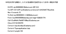
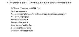
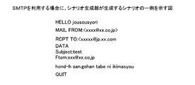
図7は、SIPを利用する場合に、シナリオ生成部36が生成するシナリオの一例を示す図である。図7において、シナリオ生成部36は、着呼先(図中「To」の行)に、通信先特定部33が特定した上位サーバ装置20の電話番号を設定し、発呼元(図中「From」の行)に、情報処理装置1の電話番号を設定する。図7に示すINVITEメッセージを受信した上位サーバ装置20は、発呼元の情報処理装置1に対する応答を送信するように、監視対象装置10へ指示する。なお、監視対象装置10aがHTTP又はSMTPを利用する場合には、シナリオ生成部36は、それぞれ対応するシナリオを生成する。図8は、HTTPを利用する場合に、シナリオ生成部36が生成するシナリオの一例を示す図である。図9は、SMTPを利用する場合に、シナリオ生成部36が生成するシナリオの一例を示す図である。図8の場合、シナリオ生成部36は、通信先(図中「GET」の行)に、通信先特定部33が特定したURLを設定する。上位サーバ装置20は、URLに基づいて、情報処理装置1へアクセスするように、監視対象装置10へ指示する。また図9の場合、シナリオ生成部36は、通信先(図中「RCPT TO」の行)に、通信先特定部33が特定したメールアドレスを設定する。上位サーバ装置20は、メールアドレスに基づいて、情報処理装置1へメールを送信するように、監視対象装置10へ指示する。なお、図7、図8及び図9に示すシナリオは、一般的なフォーマットであり、適宜変更可能である。   FIG. 7 is a diagram illustrating an example of a scenario generated by the scenario generation unit 36 when using SIP. In FIG. 7, the scenario generation unit 36 sets the telephone number of the higher-level server device 20 specified by the communication destination specifying unit 33 to the call destination (“To” line in the figure), and the caller (“ In the “From” line), the telephone number of the information processing apparatus 1 is set. Upon receiving the INVITE message shown in FIG. 7, the upper server apparatus 20 instructs the monitoring target apparatus 10 to transmit a response to the caller information processing apparatus 1. When the monitoring target device 10a uses HTTP or SMTP, the scenario generation unit 36 generates a corresponding scenario. FIG. 8 is a diagram illustrating an example of a scenario generated by the scenario generation unit 36 when HTTP is used. FIG. 9 is a diagram illustrating an example of a scenario generated by the scenario generation unit 36 when using SMTP. In the case of FIG. 8, the scenario generation unit 36 sets the URL specified by the communication destination specifying unit 33 to the communication destination (“GET” line in the figure). The host server device 20 instructs the monitoring target device 10 to access the information processing device 1 based on the URL. In the case of FIG. 9, the scenario generation unit 36 sets the mail address specified by the communication destination specifying unit 33 as the communication destination (the line “RCPT TO” in the figure). The host server device 20 instructs the monitoring target device 10 to transmit a mail to the information processing apparatus 1 based on the mail address. Note that the scenarios shown in FIGS. 7, 8, and 9 have a general format and can be changed as appropriate.

シナリオ実行部(送信部)37は、シナリオ生成部36が生成したシナリオに従って、通信状態の確認を実行する。具体的には、シナリオ実行部37は、シナリオ生成部36が生成したシナリオに従って、通信回数決定部35が決定した通信回数、上位サーバ装置20へ接続要求を送信する。このとき、シナリオ実行部37は、決定した通信回数の半分の回数、すなわち、ラウンドロビン数の回数、接続要求を送信する。送信時に、ラウンドロビン数の回数、接続要求を送信することで、情報処理装置1は、上位サーバ装置20に接続される全ての監視対象装置10との通信状態を確認できる。そして、シナリオ実行部37は、設備情報取得部34が取得した通信インターバル情報の秒数だけ待機し、通信回数の残りの回数、すなわち、ラウンドロビン数の回数、接続要求を送信する。以下の説明では、最初に通信回数の半分の回数、接続要求を送信することを、第1送信といい、残りの回数、接続要求を送信することを、第2送信という。また、第1送信時に接続要求を送信する回数を、第1送信回数といい、第2送信時に接続要求を送信する回数を、第2送信回数という。   The scenario execution unit (transmission unit) 37 executes communication status confirmation according to the scenario generated by the scenario generation unit 36. Specifically, the scenario execution unit 37 transmits a connection request to the upper server apparatus 20 for the number of communication times determined by the communication number determination unit 35 according to the scenario generated by the scenario generation unit 36. At this time, the scenario execution unit 37 transmits a connection request that is half the determined number of communications, that is, the number of round robin times. By transmitting the number of round robin times and a connection request at the time of transmission, the information processing apparatus 1 can confirm the communication state with all the monitoring target apparatuses 10 connected to the upper server apparatus 20. Then, the scenario execution unit 37 waits for the number of seconds of the communication interval information acquired by the facility information acquisition unit 34, and transmits a connection request for the remaining number of communication times, that is, the number of round robin numbers. In the following description, transmitting the connection request for the first half of the number of times of communication is referred to as first transmission, and transmitting the remaining number of times for the connection request is referred to as second transmission. In addition, the number of times that the connection request is transmitted at the time of the first transmission is referred to as the first number of times of transmission, and the number of times of transmission of the connection request at the time of the second transmission is referred to as the second number of times of transmission.

結果通知部(判定部)38は、シナリオ実行部37による実行の結果を、監視装置21へ通知する。詳しくは、結果通知部38は、接続要求の第1送信の結果を破棄して、第2送信の結果を採用し、監視装置21へ結果を通知する。上位サーバ装置20は、故障と判断した監視対象装置10aに対して閉塞処理を行うため、以降の通信には、監視対象装置10b,10cのみと通信をする。接続要求の第1送信時に閉塞処理を行った場合、第2送信時には通信の影響がなくなることがあるため、結果通知部38は、第1送信の結果を破棄し、第2送信の結果を採用する。第2送信において、接続要求を送信した第2送信回数分の応答があった場合には、結果通知部38は、監視対象装置10の通信は正常として監視装置21へ通知する。一方、第2送信回数分の応答がない場合には、結果通知部38は、監視対象装置10の通信は異常として監視装置21へ通知する。   The result notification unit (determination unit) 38 notifies the monitoring device 21 of the result of execution by the scenario execution unit 37. Specifically, the result notification unit 38 discards the result of the first transmission of the connection request, adopts the result of the second transmission, and notifies the monitoring device 21 of the result. The host server device 20 performs a blocking process on the monitored device 10a determined to be out of order, and therefore communicates only with the monitored devices 10b and 10c in subsequent communications. If the blocking process is performed at the time of the first transmission of the connection request, the effect of communication may be lost at the time of the second transmission. Therefore, the result notification unit 38 discards the result of the first transmission and adopts the result of the second transmission. To do. In the second transmission, when there is a response corresponding to the second number of transmissions when the connection request is transmitted, the result notification unit 38 notifies the monitoring device 21 that the communication of the monitoring target device 10 is normal. On the other hand, when there is no response for the second number of transmissions, the result notification unit 38 notifies the monitoring device 21 that the communication of the monitoring target device 10 is abnormal.

上述のように、上位サーバ装置20は、エラーが発生した監視対象装置10aに対して閉塞処理を行い、監視対象装置10aとの通信を回避する。このため、第1送信で監視対象装置10aとの通信ができなくても、第2送信では他の監視対象装置10b,10cと通信できるため、結果通知部38は、第2送信で接続要求を送信した第2送信回数分の応答を受信できる。この場合、結果通知部38は、監視対象装置10の通信状態が異常として通知しない。一方、上位サーバ装置20が閉塞処理を行わない場合には、上位サーバ装置20は、第2送信時でも監視対象装置10aとの通信を行なうため、情報処理装置1は、第2送信で接続要求を送信した第2送信回数分の応答を受信できない。この場合、結果通知部38は、監視対象装置10の通信は異常として監視装置21へ通知する。このように、上位サーバ装置20の機能に関係なく、常に同じ処理で、信頼性のある監視対象装置10の通信状態の確認を行える。   As described above, the upper server apparatus 20 performs a blocking process on the monitoring target apparatus 10a in which an error has occurred, and avoids communication with the monitoring target apparatus 10a. For this reason, even if communication with the monitoring target device 10a is not possible with the first transmission, communication with the other monitoring target devices 10b and 10c is possible with the second transmission, so the result notification unit 38 issues a connection request with the second transmission. Responses corresponding to the second number of transmissions transmitted can be received. In this case, the result notification unit 38 does not notify that the communication state of the monitoring target device 10 is abnormal. On the other hand, when the host server device 20 does not perform the blocking process, the host server device 20 communicates with the monitoring target device 10a even during the second transmission. Cannot receive a response corresponding to the second transmission count. In this case, the result notification unit 38 notifies the monitoring device 21 that the communication of the monitoring target device 10 is abnormal. In this way, regardless of the function of the higher-level server device 20, the communication state of the reliable monitoring target device 10 can always be confirmed by the same process.

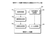
次に、管理サーバ装置22で実現される機能について説明する。図10は、管理サーバ装置22で実現される機能を示すブロック図である。図10に示す各機能は、管理サーバ装置22のCPUがROMに記憶されたプログラムを実行することで実現される。管理サーバ装置22は、結果受信部51、WEB表示処理部52、重要度決定部53、送信先決定部54、及びメール送信部55等の機能を有している。   Next, functions realized by the management server device 22 will be described. FIG. 10 is a block diagram illustrating functions implemented by the management server device 22. Each function shown in FIG. 10 is realized by the CPU of the management server device 22 executing a program stored in the ROM. The management server device 22 has functions such as a result reception unit 51, a WEB display processing unit 52, an importance level determination unit 53, a transmission destination determination unit 54, and a mail transmission unit 55.

結果受信部51は、監視装置21からの通信状態の確認結果、及びエラーログを受信する。WEB表示処理部52は、結果受信部51が受信したエラーログに基づいて、エラー名、及びエラー発生時刻等のエラー情報をWEB表示可能にする。   The result receiving unit 51 receives the confirmation result of the communication state and the error log from the monitoring device 21. Based on the error log received by the result receiving unit 51, the WEB display processing unit 52 enables error information such as an error name and an error occurrence time to be displayed on the web.

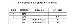
重要度決定部53は、結果受信部51が受信する通信状態の確認結果、及びエラーログに基づいて、発生したエラーの重要度を決定する。エラーの重要度は、降順に、重要度A、重要度B、重要度C及び重要度Dの4段階に分類されている。図11は、重要度を決定する方法を説明するための模式図である。エラーの重要度は、監視対象装置10との通信状態、発生したエラーの警戒レベル、発生したエラーの解析状況に基づいて決定される。なお、警戒レベルは、監視装置21においてエラー番号に基づいて特定され、特定された結果、所定レベル以上であるか否かが監視装置21からエラーログと共に通知される。また、エラーの解析状況は、例えば、受信したエラーログに、監視対象装置10aが状態確認コマンドを投入することで得られる動作状態を含んでいるかにより判定される。   The importance level determination unit 53 determines the importance level of the error that has occurred based on the confirmation result of the communication state received by the result reception unit 51 and the error log. The importance of errors is classified into four levels of importance A, importance B, importance C, and importance D in descending order. FIG. 11 is a schematic diagram for explaining a method of determining importance. The importance of the error is determined based on the communication state with the monitoring target device 10, the warning level of the error that has occurred, and the analysis status of the error that has occurred. The alert level is specified by the monitoring device 21 based on the error number. As a result of the specification, whether the alert level is equal to or higher than the predetermined level is notified from the monitoring device 21 together with the error log. The error analysis status is determined, for example, based on whether or not the received error log includes an operation state obtained by the monitoring target device 10a inputting a state confirmation command.

監視対象装置10との通信が異常の場合、重要度決定部53は、重要度Aに決定する。監視対象装置10との通信が正常であるが、発生したエラーの解析が未だの場合、重要度決定部53は、重要度Bに決定する。監視対象装置10との通信が正常で、エラーの解析が済んでおり、さらに、警戒レベルが所定レベル以上の場合、重要度決定部53は、重要度Cに決定する。監視対象装置10との通信が正常で、エラーの解析が済んでおり、さらに、警戒レベルが所定レベル以下の場合、重要度決定部53は、重要度Dに決定する。   When the communication with the monitoring target device 10 is abnormal, the importance level determination unit 53 determines the importance level A. If the communication with the monitoring target device 10 is normal but the analysis of the error that has occurred has not yet been made, the importance level determination unit 53 determines the importance level B. When the communication with the monitoring target device 10 is normal, the error has been analyzed, and the warning level is equal to or higher than the predetermined level, the importance level determination unit 53 determines the importance level C. When the communication with the monitoring target device 10 is normal, the error has been analyzed, and the warning level is equal to or lower than the predetermined level, the importance level determination unit 53 determines the importance level D.

送信先決定部54は、重要度決定部53が決定した重要度に応じて、メール送信先を決定する。具体的には、重要度Aの場合、送信先決定部54は、メール送信先を、解析者の携帯電話機100に決定する。重要度Bの場合、送信先決定部54は、メール送信先を、解析者のパソコン101に決定する。重要度C,Dの場合、送信先決定部54は、メール送信先を、運用者のパソコン102に決定する。   The transmission destination determination unit 54 determines a mail transmission destination according to the importance determined by the importance determination unit 53. Specifically, in the case of the importance level A, the transmission destination determination unit 54 determines the mail transmission destination to the analyst's mobile phone 100. In the case of importance B, the transmission destination determination unit 54 determines the mail transmission destination to be the analyst's personal computer 101. In the case of importance C and D, the transmission destination determination unit 54 determines the mail transmission destination as the personal computer 102 of the operator.

メール送信部55は、送信先決定部54が決定した送信先へ、WEB表示処理部52がWEB表示可能にしたエラー情報へのリンクを含めたメールを送信する。保守担当者は、携帯電話機100又はパソコン101,102が受信したメールのリンクから、WEB表示処理部52がWEB表示可能にしたエラー情報を確認することができる。   The mail transmission unit 55 transmits a mail including a link to the error information that the WEB display processing unit 52 can display on the web to the transmission destination determined by the transmission destination determination unit 54. The maintenance staff can check the error information that the WEB display processing unit 52 can display on the web from the link of the mail received by the mobile phone 100 or the personal computers 101 and 102.

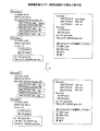
以下に、WEB表示可能にしたエラー情報を携帯電話機100で確認する場合について説明する。図12は、携帯電話機100でエラー情報を確認した場合の模式図である。管理サーバ装置22が受信したエラーログ(図12の上段左側)は、アクセスしてきた携帯電話機100で視認しやすいように、図中の四角で囲ってある必要な部分が抜き出される。アクセスしてきた携帯電話機100の画面には、その抜き出された部分、及び、監視対象装置10aに投入すべきコマンドの候補が表示される(図12の上段右側)。コマンドの候補は、選択可能に表示される。携帯電話機100でコマンドが選択された場合、管理サーバ装置22から監視対象装置10aへ選択されたコマンドが送信される。監視対象装置10aでは、選択されたコマンドが投入され、投入結果がエラーログ(図12の下段左側)として監視対象装置10aから管理サーバ装置22へ送信される。管理サーバ装置22では、再度、必要な部分が抜き出され、携帯電話機100の画面に表示される(図12の下段右側)。   Hereinafter, a case in which the mobile phone 100 confirms the error information that can be displayed on the web will be described. FIG. 12 is a schematic diagram when the mobile phone 100 confirms error information. In the error log (upper left side in FIG. 12) received by the management server device 22, a necessary part surrounded by a square in the figure is extracted so that it can be easily recognized by the mobile phone 100 that has accessed. On the screen of the mobile phone 100 that has been accessed, the extracted portion and the command candidates to be input to the monitoring target device 10a are displayed (upper right side in FIG. 12). Command candidates are displayed in a selectable manner. When a command is selected on the mobile phone 100, the selected command is transmitted from the management server device 22 to the monitoring target device 10a. In the monitoring target device 10a, the selected command is input, and the input result is transmitted from the monitoring target device 10a to the management server device 22 as an error log (lower left in FIG. 12). In the management server device 22, necessary portions are extracted again and displayed on the screen of the mobile phone 100 (lower right side in FIG. 12).

以下に、保守システムにおける動作について説明する。   The operation in the maintenance system will be described below.

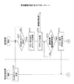
監視対象装置10に発生するエラーを検知する監視装置21における動作を説明する。図13及び図14は、監視装置21の動作を示すフローチャートである。なお、図13及び図14では、監視装置21における動作と並列して、監視対象装置10の動作を示している。   An operation in the monitoring device 21 that detects an error occurring in the monitoring target device 10 will be described. 13 and 14 are flowcharts showing the operation of the monitoring device 21. 13 and 14 show the operation of the monitoring target device 10 in parallel with the operation of the monitoring device 21.

監視対象装置10では、CPUがSNMPトラップを監視装置21へ送信する(S1)。監視装置21では、CPUがSNMPトラップを監視対象装置10aから受信したか否かを判定する(S10)。SNMPトラップを受信していない場合(S10:NO)、CPUは、受信するまで待機する。SNMPトラップを受信した場合(S10:YES)、CPUは、受信したSNMPトラップに基づいてエラーを検知し、そのSNMPトラップを送信した監視対象装置10aのIPアドレスを取得する(S11)。そして、CPUは、取得したIPアドレスを、情報処理装置1へ送信する(S12)。IPアドレスを受信した情報処理装置1では、監視対象装置10の通信状態を確認する後述の処理が行われる。   In the monitoring target device 10, the CPU transmits an SNMP trap to the monitoring device 21 (S1). In the monitoring device 21, the CPU determines whether an SNMP trap has been received from the monitoring target device 10a (S10). When the SNMP trap is not received (S10: NO), the CPU waits until it is received. When the SNMP trap is received (S10: YES), the CPU detects an error based on the received SNMP trap and acquires the IP address of the monitoring target device 10a that has transmitted the SNMP trap (S11). Then, the CPU transmits the acquired IP address to the information processing apparatus 1 (S12). In the information processing apparatus 1 that has received the IP address, a process described later for confirming the communication state of the monitoring target apparatus 10 is performed.

監視装置21では、CPUが、情報処理装置1から通信状態の確認結果を受信したか否かを判定する(S13)。受信していない場合(S13:NO)、CPUは、受信するまで待機する。受信した場合(S13:YES)、監視対象装置10aで発生したエラーに対応するエラー番号を取得し、エラーが発生した監視対象装置10aへ、エラー番号を送信する(S14)。   In the monitoring device 21, the CPU determines whether or not a communication state confirmation result has been received from the information processing device 1 (S13). When not receiving (S13: NO), CPU waits until it receives. If received (S13: YES), an error number corresponding to the error that has occurred in the monitoring target device 10a is acquired, and the error number is transmitted to the monitoring target device 10a in which the error has occurred (S14).

監視対象装置10では、監視装置21からエラー番号を受信したか否かを判定する(S2)。監視対象装置10でエラーが発生していない場合には、監視装置21からエラー番号が送信されることはないため、エラー番号を受信していない場合(S2:NO)、監視対象装置10では、処理が終了する。監視装置21からエラー番号を受信した場合(S2:YES)、監視対象装置10のCPUは、受信したエラー番号に基づいて、発生したエラーの解析に必要なログを抽出する(S3)。具体的には、CPUは、状態確認コマンドを投入し、その結果得られる自身の動作状態を取得する。CPUは、抽出したログをエラーログとして監視装置21へ送信する(S4)。その後、監視対象装置10では、処理が終了する。   The monitoring target device 10 determines whether an error number has been received from the monitoring device 21 (S2). If no error has occurred in the monitoring target device 10, an error number is not transmitted from the monitoring device 21. Therefore, if no error number has been received (S <b> 2: NO), the monitoring target device 10 The process ends. When an error number is received from the monitoring device 21 (S2: YES), the CPU of the monitoring target device 10 extracts a log necessary for analyzing the generated error based on the received error number (S3). Specifically, the CPU inputs a state confirmation command, and acquires its own operation state obtained as a result. The CPU transmits the extracted log as an error log to the monitoring device 21 (S4). Thereafter, the process ends in the monitoring target device 10.

監視装置21では、エラー番号を送信した後、CPUが、エラーログを監視対象装置10から受信したか否かを判定する(S15)。エラーログを受信していない場合(S15:NO)、CPUは、エラー番号を送信してから所定時間が経過したか否かを判定する(S16)。所定時間が経過していない場合(S16:NO)、CPUは、S15の処理に戻る。所定時間が経過した場合(S16:YES)、CPUは、S14で取得したエラー番号、及び通信状態の確認結果を管理サーバ装置22へ送信し(S17)、本処理を終了する。エラーログを監視対象装置10から受信した場合(S15:YES)、CPUは、エラー番号、受信したエラーログ及び通信状態の確認結果を管理サーバ装置22へ送信し(S18)、本処理を終了する。   In the monitoring device 21, after transmitting the error number, the CPU determines whether an error log has been received from the monitoring target device 10 (S15). When the error log has not been received (S15: NO), the CPU determines whether or not a predetermined time has elapsed since the error number was transmitted (S16). When the predetermined time has not elapsed (S16: NO), the CPU returns to the process of S15. When the predetermined time has elapsed (S16: YES), the CPU transmits the error number acquired in S14 and the confirmation result of the communication state to the management server device 22 (S17), and ends this process. When the error log is received from the monitoring target device 10 (S15: YES), the CPU transmits the error number, the received error log, and the communication status confirmation result to the management server device 22 (S18), and ends this processing. .

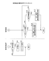
次に、監視対象装置10aにエラーが発生した場合、エラーの重要度を決定するために監視対象装置10aの通信状態を確認する情報処理装置1における動作について説明する。図15及び図16は、情報処理装置1の動作を示すフローチャートである。   Next, an operation in the information processing apparatus 1 that checks the communication state of the monitoring target device 10a in order to determine the importance of the error when an error occurs in the monitoring target device 10a will be described. 15 and 16 are flowcharts illustrating the operation of the information processing apparatus 1.

情報処理装置1のCPU2は、エラーの発生を検知した監視装置21からIPアドレスを受信したか否かを判定する(S21)。IPアドレスを受信していない場合(S21:NO)、CPU2は、受信するまで待機する。IPアドレスを受信した場合(S21:YES)、CPU2は、IPアドレスとプロトコルDB41とに基づいて、エラーが発生した監視対象装置10aの運用に必要なプロトコル、及びそのプロトコルのフォーマットを特定する(S22)。   The CPU 2 of the information processing device 1 determines whether an IP address has been received from the monitoring device 21 that has detected the occurrence of an error (S21). When the IP address has not been received (S21: NO), the CPU 2 stands by until it is received. When the IP address is received (S21: YES), the CPU 2 specifies the protocol necessary for the operation of the monitored apparatus 10a in which the error has occurred and the format of the protocol based on the IP address and the protocol DB 41 (S22). ).

次に、CPU2は、受信したIPアドレス及び特定したプロトコルに基づいて、通信先を特定する(S23)。例えば、エラーが発生した監視対象装置10aがSIPを利用する場合、CPU2は、通信先DB42から、監視対象装置10aの上位サーバ装置20の電話番号を特定する。続いて、CPU2は、受信したIPアドレス、及び、特定したプロトコルに基づいて、エラーが発生した監視対象装置10aが接続している上位サーバ装置20のラウンドロビン数を取得する(S24)。また、CPU2は、その上位サーバ装置20の通信インターバル情報を取得する(S25)。CPU2は、取得したラウンドロビン数に「2」を乗算した値を、通信回数として決定する(S26)。   Next, the CPU 2 specifies a communication destination based on the received IP address and the specified protocol (S23). For example, when the monitoring target device 10a in which the error has occurred uses SIP, the CPU 2 specifies the telephone number of the higher-level server device 20 of the monitoring target device 10a from the communication destination DB. Subsequently, based on the received IP address and the specified protocol, the CPU 2 obtains the round robin number of the upper server device 20 to which the monitored device 10a in which the error has occurred is connected (S24). Further, the CPU 2 acquires communication interval information of the higher-level server device 20 (S25). The CPU 2 determines a value obtained by multiplying the acquired number of round robin by “2” as the number of communication (S26).

次に、CPU2は、エラーが発生した監視対象装置10aの上位サーバ装置20へ接続要求を送信するためのシナリオを生成する(S27)。例えば、上位サーバ装置20がSIPサーバ装置の場合には、CPU2は、図7に示すINVITEメッセージを生成する。CPU2は、生成したシナリオに従って、接続要求を上位サーバ装置20へ送信し(S28)、第1送信回数、接続要求を送信したか否かを判定する(S29)。第1送信回数は、決定した通信回数の半分の回数、すなわち、ラウンドロビン数である。ラウンドロビン数の回数、接続要求を送信することで、上位サーバ装置20に接続される全ての監視対象装置10との通信状態を確認できる。第1送信回数、接続要求を送信していない場合(S29:NO)、CPU2は、S28の処理を実行し、接続要求を送信し続ける。第1送信回数、接続要求を送信した場合(S29:YES)、CPU2は、S25で取得した通信インターバル情報の秒数だけ待機する(S30)。インターバルを設定して、待機することで、タイムアウトか否かを判定する処理を行うために、情報処理装置1が監視対象装置10からの応答を受信できなくなることを回避することができる。   Next, the CPU 2 generates a scenario for transmitting a connection request to the upper server device 20 of the monitoring target device 10a in which an error has occurred (S27). For example, when the upper server device 20 is a SIP server device, the CPU 2 generates an INVITE message shown in FIG. In accordance with the generated scenario, the CPU 2 transmits a connection request to the higher-level server device 20 (S28), and determines whether or not the first transmission count and the connection request have been transmitted (S29). The first transmission count is a half of the determined communication count, that is, the round robin count. By transmitting the number of round robin times and the connection request, it is possible to check the communication state with all the monitoring target devices 10 connected to the higher level server device 20. When the connection request is not transmitted for the first transmission count (S29: NO), the CPU 2 executes the process of S28 and continues to transmit the connection request. When the first transmission count and the connection request are transmitted (S29: YES), the CPU 2 waits for the number of seconds of the communication interval information acquired in S25 (S30). By setting an interval and waiting, it is possible to prevent the information processing apparatus 1 from receiving a response from the monitoring target apparatus 10 in order to perform processing for determining whether or not a timeout has occurred.

その後、CPU2は、第2送信を開始し、接続要求を上位サーバ装置20へ送信する(S31)。CPU2は、第2送信回数、接続要求を送信したか否かを判定する(S32)。第2送信回数、接続要求を送信していない場合(S32:NO)、CPU2は、S31の処理に戻り、接続要求を送信し続ける。第2送信回数、接続要求を送信した場合(S32:YES)、CPU2は、監視対象装置10の通信状態が正常か否かを判定する(S33)。具体的には、CPU2は、第1送信における応答結果を破棄し、第2送信において、第2送信回数と同じ回数、応答を受信したか否かを判定する。上位サーバ装置20が上述の閉塞処理を行う場合には、第2送信時で接続要求を送信した第2送信回数と同じ回数、応答を受信する。このため、CPU2は、監視対象装置10aとは通信できなくても、他の監視対象装置10b,10cと通信できるため、通信状態は正常と判定する。一方、上位サーバ装置20が閉塞処理を行わない場合には、第2送信時で接続要求を送信した第2送信回数と同じ回数、応答を受信しない。このため、CPU2は、監視対象装置10aとは通信できないとして、通信状態は正常と判定する。   Thereafter, the CPU 2 starts the second transmission and transmits a connection request to the upper server apparatus 20 (S31). The CPU 2 determines whether or not a connection request has been transmitted for the second number of transmissions (S32). When the second transmission count and the connection request are not transmitted (S32: NO), the CPU 2 returns to the process of S31 and continues to transmit the connection request. When the second transmission count and the connection request are transmitted (S32: YES), the CPU 2 determines whether or not the communication state of the monitoring target device 10 is normal (S33). Specifically, the CPU 2 discards the response result in the first transmission and determines whether or not the response has been received the same number of times as the second transmission number in the second transmission. When the higher-level server apparatus 20 performs the above-described blocking process, the response is received the same number of times as the second transmission count in which the connection request is transmitted at the time of the second transmission. For this reason, since the CPU 2 can communicate with the other monitoring target devices 10b and 10c even if it cannot communicate with the monitoring target device 10a, the CPU 2 determines that the communication state is normal. On the other hand, when the host server device 20 does not perform the blocking process, the response is not received the same number of times as the second number of times of transmission of the connection request at the time of the second transmission. For this reason, the CPU 2 determines that the communication state is normal because it cannot communicate with the monitoring target device 10a.

監視対象装置10の通信状態が正常の場合(S33:YES)、CPU2は、通信状態は「正常」であることを監視装置21へ通知し(S34)、本処理を終了する。監視対象装置10の通信状態が正常でない場合(S33:NO)、CPU2は、通信状態は「異常」であることを監視装置21へ通知し(S35)、本処理を終了する。   When the communication state of the monitoring target device 10 is normal (S33: YES), the CPU 2 notifies the monitoring device 21 that the communication state is “normal” (S34), and ends this process. When the communication state of the monitoring target apparatus 10 is not normal (S33: NO), the CPU 2 notifies the monitoring apparatus 21 that the communication state is “abnormal” (S35), and ends this process.

次に、接続要求を受信し、情報処理装置1と監視対象装置10とを接続する上位サーバ装置20における動作について説明する。図17は、上位サーバ装置20の動作を示すフローチャートである。   Next, an operation in the upper server apparatus 20 that receives the connection request and connects the information processing apparatus 1 and the monitoring target apparatus 10 will be described. FIG. 17 is a flowchart showing the operation of the upper server apparatus 20.

上位サーバ装置20では、CPUが情報処理装置1から接続要求を受信したか否かを判定する(S41)。受信していない場合(S41:NO)、CPUは本処理を終了する。受信した場合(S41:YES)、CPUは、ラウンドロビン方式に従って、接続されている監視対象装置10へ、接続要求を送信する(S42)。次に、CPUは、接続要求を送信した監視対象装置10から応答を受信したか否かを判定する(S43)。受信した場合(S43:YES)、CPUは、受信した応答を、情報処理装置1へ送信し(S44)、本処理を終了する。   In the host server device 20, the CPU determines whether or not it has received a connection request from the information processing device 1 (S41). When not receiving (S41: NO), CPU complete | finishes this process. If received (S41: YES), the CPU transmits a connection request to the connected monitoring target device 10 according to the round robin method (S42). Next, the CPU determines whether or not a response has been received from the monitoring target device 10 that has transmitted the connection request (S43). If received (S43: YES), the CPU transmits the received response to the information processing apparatus 1 (S44), and ends this process.

応答を受信していない場合(S43:NO)、CPUは、監視対象装置10へ接続要求を送信してから、所定時間経過したか否かを判定する(S45)。所定時間経過していない場合(S45:NO)、CPUは、S43の処理を実行する。所定時間経過した場合(S45:YES)、CPUは、応答を送信しない監視対象装置10に対して、閉塞処理を実行する(S46)。これにより、以降の処理では、上位サーバ装置20は、閉塞処理を実行した監視対象装置10に対しては、接続要求を送信しなくなる。   When the response has not been received (S43: NO), the CPU determines whether or not a predetermined time has elapsed since the connection request was transmitted to the monitoring target device 10 (S45). When the predetermined time has not elapsed (S45: NO), the CPU executes the process of S43. When the predetermined time has elapsed (S45: YES), the CPU executes a blocking process on the monitoring target device 10 that does not transmit a response (S46). Thereby, in the subsequent processes, the higher-level server apparatus 20 does not transmit a connection request to the monitoring target apparatus 10 that has executed the blocking process.

次に、発生したエラーの重要度を決定する管理サーバ装置22における動作について説明する。図18及び図19は、管理サーバ装置22の動作を示すフローチャートである。   Next, the operation in the management server device 22 that determines the importance of the error that has occurred will be described. 18 and 19 are flowcharts showing the operation of the management server device 22.

管理サーバ装置22のCPUは、監視装置21から各情報を受信したか否かを判定する(S51)。具体的には、受信する情報とは、エラー番号、通信状態の確認結果、及びエラーログ等である。なお、エラーが発生した監視対象装置10aから監視装置21へエラーログが送信されない場合、CPUは、エラー番号、及び通信状態の確認結果を受信したか否かを判定する。受信していない場合(S51:NO)、CPUは、受信するまで待機する。受信した場合(S51:YES)、エラー番号及びエラーログに基づいて、エラー名、及びエラー発生時刻等のエラー情報をWEB表示可能にする処理を行う(S52)。   The CPU of the management server device 22 determines whether each piece of information has been received from the monitoring device 21 (S51). Specifically, the received information includes an error number, a confirmation result of the communication state, an error log, and the like. When an error log is not transmitted from the monitored device 10a in which an error has occurred to the monitoring device 21, the CPU determines whether an error number and a communication state confirmation result have been received. When not receiving (S51: NO), CPU waits until it receives. If received (S51: YES), based on the error number and error log, a process for enabling error display such as error name and error occurrence time to be displayed on the web (S52).

次に、CPUは、図11で説明したように、発生したエラーの重要度を決定する(S53)。CPUは、決定した重要度が、「重要度A」であるか否かを判定する(S54)。決定した重要度が「重要度A」である場合(S54:YES)、CPUは、解析者の携帯電話機100へメールを送信し(S55)、S59の処理へ移る。送信するメールには、S52でWEB表示可能にしたエラー情報へのアクセス先(リンク情報)が含まれている。決定した重要度が「重要度A」でない場合(S54:NO)、CPUは、決定した重要度が「重要度B」であるか否かを判定する(S56)。決定した重要度が「重要度B」である場合(S56:YES)、CPUは、解析者のパソコン101へメールを送信し(S57)、S59の処理へ移る。決定した重要度が「重要度B」でない場合(S56:NO)、すなわち、重要度が「重要度C」又は「重要度D」の場合、CPUは、運用者のパソコン102へメールを送信する(S58)。そして、CPUは、S59の処理へ移る。   Next, as described with reference to FIG. 11, the CPU determines the importance of the error that has occurred (S53). The CPU determines whether or not the determined importance is “importance A” (S54). When the determined importance is “importance A” (S54: YES), the CPU transmits a mail to the analyst's mobile phone 100 (S55), and proceeds to the processing of S59. The mail to be sent includes an access destination (link information) to the error information that can be displayed on the web in S52. When the determined importance is not “importance A” (S54: NO), the CPU determines whether or not the determined importance is “importance B” (S56). When the determined importance is “importance B” (S56: YES), the CPU transmits an email to the personal computer 101 of the analyst (S57), and proceeds to the process of S59. When the determined importance is not “importance B” (S56: NO), that is, when the importance is “importance C” or “importance D”, the CPU transmits an email to the personal computer 102 of the operator. (S58). Then, the CPU proceeds to the process of S59.

CPUは、メールを送信した携帯電話機100又はパソコン101,102からアクセスされたか否かを判定する(S59)。アクセスされていない場合(S59:NO)、CPUは、アクセスされるまで待機する。なお、所定時間アクセスされない場合には、CPUは、処理を終了するようにしてもよい。アクセスされた場合(S59:YES)、CPUは、HTTPにより、S52の処理でWEB表示可能にした情報を、アクセス元へ送信する(S60)。これにより、アクセス元の携帯電話機100又はパソコン101,102の画面には、図12で説明したように、エラー情報が表示され、投入コマンドが選択可能に表示される。   The CPU determines whether access has been made from the mobile phone 100 or the personal computers 101, 102 that transmitted the mail (S59). If not accessed (S59: NO), the CPU waits until accessed. Note that if the access is not made for a predetermined time, the CPU may end the process. When accessed (S59: YES), the CPU transmits the information that can be displayed on the web in the process of S52 to the access source by HTTP (S60). As a result, the error information is displayed on the screen of the access source mobile phone 100 or the personal computers 101 and 102 as shown in FIG. 12, and the input command can be selected.

CPUは、アクセス元の携帯電話機100又はパソコン101,102でコマンドが選択され、そのコマンドを受け付けたか否かを判定する(S61)。コマンドを受け付けていない場合(S61:NO)、CPUは、受け付けるまで待機する。コマンドを受け付けた場合(S61:YES)、CPUは、受け付けたコマンドが完了コマンドであるか否かを判定する(S62)。完了コマンドは、保守管理者が、エラーが解消したと判断した場合に、選択される。受け付けたコマンドが完了コマンドである場合(S62:YES)、CPUは、本処理を終了する。受け付けたコマンドが完了コマンドでない場合(S62:NO)、CPUは、対応するコマンドを、エラーが発生した監視対象装置10aへ送信する(S63)。そして、CPUは、そのコマンドに対する結果を受信したか否かを判定する(S64)。受信していない場合(S64:NO)、CPUは、受信するまで待機する。受信した場合(S64:YES)、CPUは、受信した結果を、WEB表示可能に処理する(S65)。その後、CPUは、S61の処理を実行し、再びコマンドを受け付けたか否かを判定する。   The CPU determines whether a command is selected on the access source mobile phone 100 or the personal computers 101, 102 and the command is accepted (S61). If no command is received (S61: NO), the CPU waits until it is received. When a command is received (S61: YES), the CPU determines whether the received command is a completion command (S62). The completion command is selected when the maintenance manager determines that the error has been resolved. When the received command is a completion command (S62: YES), the CPU ends this process. When the received command is not a completion command (S62: NO), the CPU transmits a corresponding command to the monitoring target device 10a in which the error has occurred (S63). Then, the CPU determines whether or not a result for the command has been received (S64). When not receiving (S64: NO), CPU waits until it receives. If received (S64: YES), the CPU processes the received result so that it can be displayed on the web (S65). Thereafter, the CPU executes the process of S61 and determines whether or not a command has been received again.

以上説明したように、本実施の形態では、情報処理装置1は、エラーが発生した監視対象装置10との通信状態を確認する場合、接続要求の送信を第1送信及び第2送信に分けて行なう。そして、第1送信に対する応答を破棄して、第2送信に対する応答に基づいて、監視対象装置10との通信状態を確認する。上位サーバ装置20によっては、エラーが発生した監視対象装置10に対して閉塞処理を行い、以降、その監視対象装置10との通信を避ける機能を有している。このため、第1送信では応答を受信しなくても、第2送信で応答を受信する場合がある。そこで、第2送信に対する応答に基づいて、監視対象装置10の通信状態を確認することで、上位サーバ装置20が有する機能に関係なく、同じ処理で、より精度の高い通信状態の確認を行うことができる。その結果、通信異常が監視対象装置10の運用に問題を引き起こす場合、通信状態を確実に把握することで、通信状態に応じたエラーの重要度を決定することが可能となり、最適なエラー対策を行なえる。   As described above, in the present embodiment, when the information processing apparatus 1 confirms the communication state with the monitoring target apparatus 10 in which an error has occurred, the connection request transmission is divided into the first transmission and the second transmission. Do. Then, the response to the first transmission is discarded, and the communication state with the monitoring target device 10 is confirmed based on the response to the second transmission. Depending on the higher-level server device 20, the monitoring target device 10 in which an error has occurred is blocked, and thereafter has a function of avoiding communication with the monitoring target device 10. For this reason, even if the response is not received in the first transmission, the response may be received in the second transmission. Therefore, by confirming the communication state of the monitoring target device 10 based on the response to the second transmission, the communication state can be confirmed with higher accuracy in the same process regardless of the function of the upper server device 20. Can do. As a result, when a communication error causes a problem in the operation of the monitoring target device 10, it is possible to determine the importance of the error according to the communication state by reliably grasping the communication state, and to take an optimal error countermeasure. Yes.

本発明の実施形態について、具体的に説明したが、各構成及び動作等は適宜変更可能であって、上述の実施形態に限定されることはない。例えば、監視装置21及び管理サーバ装置22の機能は、一つの装置で実現するように構成してもよい。また、エラー発生時には、メールにて保守担当者に通知しているが、携帯電話機に電話をかけて、自動音声で通知するようにしてもよい。   Although the embodiment of the present invention has been specifically described, each configuration, operation, and the like can be changed as appropriate, and are not limited to the above-described embodiment. For example, the functions of the monitoring device 21 and the management server device 22 may be configured to be realized by a single device. In addition, when an error occurs, the person in charge of maintenance is notified by e-mail, but it may be notified by automatic voice by calling a mobile phone.

また、本実施の形態では、上位サーバ装置20は、エラーがある監視対象装置10に対して閉塞処理を行うものとしているが、上位サーバ装置20を複数設ける場合、全ての上位サーバ装置20を、閉塞処理を行う装置とする必要はない。異なる機能を有する上位サーバ装置20が混在している場合であっても、第1送信で送信した接続要求に対する結果を破棄することで、情報処理装置1は、上位サーバ装置20の種類を把握することなく、一様に同じ処理で通信状態を確認することができる。   In this embodiment, the upper server apparatus 20 performs the blocking process on the monitoring target apparatus 10 having an error. However, when a plurality of upper server apparatuses 20 are provided, all the upper server apparatuses 20 are It is not necessary to use a device that performs blockage processing. Even when the higher-level server devices 20 having different functions are mixed, the information processing device 1 recognizes the type of the higher-level server device 20 by discarding the result for the connection request transmitted in the first transmission. The communication state can be confirmed uniformly by the same process.

本実施の形態では、上位サーバ装置20のラウンドロビンの数の回数、接続要求を送信する第1及び第2送信を行なっているが、送信回数は、上位サーバ装置20が有する機能に応じて適宜変更可能である。例として、情報処理装置1は、第1送信において、接続要求の送信先にエラーが発生した監視対象装置10aを指定する。上位サーバ装置20は、エラーが発生した監視対象装置10aとの通信を行い、故障と判断した場合、監視対象装置10aに閉塞処理を行う。続いて、第2送信で接続要求を受信した上位サーバ装置20は、自動的に、他の監視対象装置10b,10cとの通信を行なう。このような場合、第1及び第2送信回数は、1回でよくなり、第2送信における応答を受信すれば、情報処理装置1は、通信状態を「正常」と判定する。   In the present embodiment, the number of round robin times of the higher-level server device 20 and the first and second transmissions for transmitting the connection request are performed. The number of transmissions is appropriately determined according to the function of the higher-level server device 20. It can be changed. As an example, the information processing apparatus 1 specifies the monitoring target apparatus 10a in which an error has occurred in the connection request transmission destination in the first transmission. The host server device 20 communicates with the monitoring target device 10a in which an error has occurred, and performs a blocking process on the monitoring target device 10a when it is determined that a failure has occurred. Subsequently, the host server device 20 that has received the connection request by the second transmission automatically communicates with the other monitoring target devices 10b and 10c. In such a case, the first and second transmission times may be one, and if the response in the second transmission is received, the information processing apparatus 1 determines that the communication state is “normal”.

また、本実施の形態では、上位サーバ装置20がラウンドロビン方式に従って、監視対象装置10と通信するようにしているが、情報処理装置1と監視対象装置10との通信方式は、これに限定されることはない。例えば、第1送信において、情報処理装置1は、エラーが発生した監視対象装置10aを送信先に指定した接続要求を上位サーバ装置20へ送信する。監視対象装置10aが故障と判断した場合、上位サーバ装置20は、監視対象装置10aに対して閉塞処理を行い、以降、監視対象装置10aを送信先に指定した接続要求を受信した場合であっても、上位サーバ装置20は、監視対象装置10aと通信を行わないようにする。この場合、情報処理装置1は、第1送信で接続要求に対する応答がなくても、第2送信で応答を受信することができる。すなわち、情報処理装置1は、第1及び第2送信で、一回のみ接続要求を送信することで、監視対象装置10の通信状態を確認することができる。   Further, in the present embodiment, the upper server apparatus 20 communicates with the monitoring target apparatus 10 in accordance with the round robin method, but the communication method between the information processing apparatus 1 and the monitoring target apparatus 10 is limited to this. Never happen. For example, in the first transmission, the information processing apparatus 1 transmits to the upper server apparatus 20 a connection request that designates the monitoring target apparatus 10a in which the error has occurred as a transmission destination. When the monitoring target device 10a is determined to be faulty, the higher-level server device 20 performs a blocking process on the monitoring target device 10a, and thereafter receives a connection request specifying the monitoring target device 10a as a transmission destination. In addition, the host server device 20 is configured not to communicate with the monitoring target device 10a. In this case, the information processing apparatus 1 can receive a response by the second transmission even if there is no response to the connection request by the first transmission. That is, the information processing apparatus 1 can confirm the communication state of the monitoring target apparatus 10 by transmitting the connection request only once in the first and second transmissions.

以下に、上述の実施形態を含む実施形態に関し、更に付記を開示する。   Hereinafter, additional notes will be disclosed regarding the embodiment including the above-described embodiment.

(付記1)
複数の被監視装置が接続され、接続要求信号を前記被監視装置に分配する外部装置に、接続要求信号を送信することで、前記被監視装置の通信状態を確認する通信確認装置において、
前記被監視装置にエラーが発生したことを検知する検知部と、
前記被監視装置、及び該被監視装置が接続される外部装置の接続先を記憶する通信先記憶部と、
該検知部がエラーを検知した場合、前記通信先記憶部に記憶した接続先に基づいて接続要求信号を前記外部装置へ二回送信する送信部と、
該送信部が二回目に送信した接続要求信号に対する応答信号を受信したか否かを判定する判定部と
を備える通信確認装置。
(Appendix 1)
In a communication confirmation device for confirming the communication state of the monitored device by transmitting a connection request signal to an external device to which a plurality of monitored devices are connected and distributing a connection request signal to the monitored device.
A detection unit for detecting that an error has occurred in the monitored device;
A communication destination storage unit that stores a connection destination of the monitored device and an external device to which the monitored device is connected;
When the detection unit detects an error, a transmission unit that transmits a connection request signal twice to the external device based on the connection destination stored in the communication destination storage unit;
And a determination unit that determines whether or not a response signal to the connection request signal transmitted by the transmission unit for the second time has been received.

(付記2)
前記外部装置に接続されている被監視装置の数を記憶する数記憶部と、
前記検知部がエラーを検知した場合、前記外部装置に接続されている被監視装置の数を、前記数記憶部の記憶内容から特定する数特定部と
をさらに備え、
前記送信部は、
前記数特定部が特定した数を、一回目及び二回目それぞれの接続要求信号の送信回数として、接続要求信号を送信するようにしてある
付記1に記載の通信確認装置。
(Appendix 2)
A number storage unit for storing the number of monitored devices connected to the external device;
When the detection unit detects an error, further comprising: a number specifying unit for specifying the number of monitored devices connected to the external device from the storage content of the number storage unit,
The transmitter is
The communication confirmation apparatus according to claim 1, wherein the connection request signal is transmitted by using the number specified by the number specifying unit as the number of times of transmission of the first and second connection request signals.

(付記3)
前記送信部は、
一回目の接続要求信号の送信終了後、所定時間経過後に、二回目の接続要求信号を送信するようにしてある
付記1又は2に記載の通信確認装置。
(Appendix 3)
The transmitter is
The communication confirmation apparatus according to appendix 1 or 2, wherein a second connection request signal is transmitted after a predetermined time has elapsed after the transmission of the first connection request signal.

(付記4)
前記検知部がエラーを検知した場合、エラーが発生した被監視装置を特定する装置特定部
をさらに備え、
前記送信部は、
一回目の送信で、前記装置特定部が特定した被監視装置を送信先に指定し、前記外部装置へ接続要求を送信するようにしてある
付記1から3の何れか一つに記載の通信確認装置。
(Appendix 4)
When the detection unit detects an error, the device further includes a device specifying unit that specifies a monitored device in which the error has occurred,
The transmitter is
In the first transmission, the monitored device specified by the device specifying unit is designated as a transmission destination, and a connection request is transmitted to the external device. Communication check according to any one of appendices 1 to 3 apparatus.

(付記5)
複数の被監視装置が接続され、接続要求信号を前記被監視装置に分配する外部装置に、接続要求信号を送信することで、前記被監視装置の通信状態を確認する通信確認方法において、
前記被監視装置にエラーが発生したことを検知し、
前記被監視装置、及び該被監視装置が接続される外部装置の接続先を記憶し、
エラーを検知した場合、記憶した接続先に基づいて前記外部装置へ接続要求信号を二回送信し、
二回目に送信した接続要求信号に対する応答信号を受信したか否かを判定する
通信確認方法。
(Appendix 5)
In a communication confirmation method for confirming a communication state of the monitored device by transmitting a connection request signal to an external device to which a plurality of monitored devices are connected and distributing a connection request signal to the monitored device.
Detecting that an error has occurred in the monitored device,
Storing a connection destination of the monitored device and an external device to which the monitored device is connected;
If an error is detected, a connection request signal is transmitted twice to the external device based on the stored connection destination,
A communication confirmation method for determining whether or not a response signal to the connection request signal transmitted for the second time has been received.

(付記6)
複数の被監視装置が接続され、接続要求信号を前記被監視装置に分配する外部装置に、接続要求信号を送信するコンピュータで実行されるプログラムにおいて、
コンピュータを、
前記被監視装置にエラーが発生したことを検知する検知部、
該検知部がエラーを検知した場合、記憶された、前記被監視装置、及び該被監視装置が接続される外部装置の接続先に基づいて、接続要求信号を前記外部装置へ二回送信させる送信部、及び、
該送信部が二回目に送信させた接続要求信号に対する応答信号を受信したか否かを判定する判定部
として機能させるプログラム。
(Appendix 6)
In a program executed by a computer that transmits a connection request signal to an external device to which a plurality of monitored devices are connected and distributes a connection request signal to the monitored devices.
Computer
A detection unit for detecting that an error has occurred in the monitored device;
When the detection unit detects an error, based on the stored device to be monitored and the connection destination of the external device to which the monitored device is connected, transmission that transmits a connection request signal to the external device twice Part and
A program that functions as a determination unit that determines whether or not a response signal to the connection request signal transmitted by the transmission unit for the second time has been received.

(付記7)
付記6に記載のプログラムが記録されており、コンピュータでの読取り可能な記録媒体。
(Appendix 7)
A computer-readable recording medium on which the program according to appendix 6 is recorded.

1 情報処理装置
5 大容量記憶装置(数記憶部、通信先記憶部)
10 監視対象装置(被監視装置)
20 上位サーバ装置(外部装置)
21 監視装置
22 管理サーバ装置
31 IPアドレス受信部(検知部)
34 設備情報取得部(特定部)
37 シナリオ実行部(送信部)
38 結果通知部(判定部)
41 プロトコルDB
42 通信先DB(通信先記憶部)
43 設備情報DB(数記憶部)
100 携帯電話機
101,102 パソコン
1 Information processing device 5 Mass storage device (number storage unit, communication destination storage unit)
10 Monitoring target device (monitored device)
20 Host server device (external device)
21 Monitoring device 22 Management server device 31 IP address receiving unit (detecting unit)
34 Equipment information acquisition part (specific part)
37 Scenario execution part (transmission part)
38 Result Notification Unit (Decision Unit)
41 Protocol DB
42 communication destination DB (communication destination storage unit)
43 Equipment information DB (number storage unit)
100 Mobile phone 101, 102 PC

Claims (5)

複数の被監視装置が接続され、接続要求信号を前記被監視装置に分配する外部装置に、接続要求信号を送信することで、前記被監視装置の通信状態を確認する通信確認装置において、
前記被監視装置にエラーが発生したことを検知する検知部と、
前記被監視装置、及び該被監視装置が接続される外部装置の接続先を記憶する通信先記憶部と、
該検知部がエラーを検知した場合、前記通信先記憶部に記憶した接続先に基づいて接続要求信号を前記外部装置へ二回送信する送信部と、
該送信部が二回目に送信した接続要求信号に対する応答信号を受信したか否かを判定する判定部と
を備える通信確認装置。
In a communication confirmation device for confirming the communication state of the monitored device by transmitting a connection request signal to an external device to which a plurality of monitored devices are connected and distributing a connection request signal to the monitored device.
A detection unit for detecting that an error has occurred in the monitored device;
A communication destination storage unit that stores a connection destination of the monitored device and an external device to which the monitored device is connected;
When the detection unit detects an error, a transmission unit that transmits a connection request signal twice to the external device based on the connection destination stored in the communication destination storage unit;
And a determination unit that determines whether or not a response signal to the connection request signal transmitted by the transmission unit for the second time has been received.
前記外部装置に接続されている被監視装置の数を記憶する数記憶部と、
前記検知部がエラーを検知した場合、前記外部装置に接続されている被監視装置の数を、前記数記憶部の記憶内容から特定する特定部と
をさらに備え、
前記送信部は、
前記特定部が特定した数を、一回目及び二回目それぞれの接続要求信号の送信回数として、接続要求信号を送信するようにしてある
請求項1に記載の通信確認装置。
A number storage unit for storing the number of monitored devices connected to the external device;
When the detection unit detects an error, further comprising: a specifying unit that specifies the number of monitored devices connected to the external device from the stored contents of the number storage unit,
The transmitter is
The communication confirmation apparatus according to claim 1, wherein the connection request signal is transmitted by using the number specified by the specifying unit as the number of times of transmission of the first and second connection request signals.
前記送信部は、
一回目の接続要求信号の送信終了後、所定時間経過後に、二回目の接続要求信号を送信するようにしてある
請求項1又は2に記載の通信確認装置。
The transmitter is
The communication confirmation apparatus according to claim 1 or 2, wherein a second connection request signal is transmitted after a predetermined time has elapsed after the transmission of the first connection request signal.
複数の被監視装置が接続され、接続要求信号を前記被監視装置に分配する外部装置に、接続要求信号を送信することで、前記被監視装置の通信状態を確認する通信確認方法において、
前記被監視装置にエラーが発生したことを検知し、
前記被監視装置、及び該被監視装置が接続される外部装置の接続先を記憶し、
エラーを検知した場合、記憶した接続先に基づいて前記外部装置へ接続要求信号を二回送信し、
二回目に送信した接続要求信号に対する応答信号を受信したか否かを判定する
通信確認方法。
In the communication confirmation method for confirming the communication state of the monitored device by transmitting a connection request signal to an external device to which a plurality of monitored devices are connected and distributing a connection request signal to the monitored device.
Detecting that an error has occurred in the monitored device,
Storing a connection destination of the monitored device and an external device to which the monitored device is connected;
If an error is detected, a connection request signal is transmitted twice to the external device based on the stored connection destination,
A communication confirmation method for determining whether or not a response signal to the connection request signal transmitted for the second time has been received.
複数の被監視装置が接続され、接続要求信号を前記被監視装置に分配する外部装置に、接続要求信号を送信するコンピュータで実行されるプログラムにおいて、
コンピュータを、
前記被監視装置にエラーが発生したことを検知する検知部、
該検知部がエラーを検知した場合、記憶された、前記被監視装置、及び該被監視装置が接続される外部装置の接続先に基づいて、接続要求信号を前記外部装置へ二回送信させる送信部、及び、
該送信部が二回目に送信させた接続要求信号に対する応答信号を受信したか否かを判定する判定部
として機能させるプログラム。
In a program executed by a computer that transmits a connection request signal to an external device to which a plurality of monitored devices are connected and distributes a connection request signal to the monitored devices.
Computer
A detection unit for detecting that an error has occurred in the monitored device;
When the detection unit detects an error, based on the stored device to be monitored and the connection destination of the external device to which the monitored device is connected, transmission that transmits a connection request signal to the external device twice Part and
A program that functions as a determination unit that determines whether or not a response signal to the connection request signal transmitted by the transmission unit for the second time has been received.
JP2010098106A 2010-04-21 2010-04-21 Communication confirmation device, communication confirmation method and program Expired - Fee Related JP5471765B2 (en)

Priority Applications (1)

Application Number Priority Date Filing Date Title
JP2010098106A JP5471765B2 (en) 2010-04-21 2010-04-21 Communication confirmation device, communication confirmation method and program

Applications Claiming Priority (1)

Application Number Priority Date Filing Date Title
JP2010098106A JP5471765B2 (en) 2010-04-21 2010-04-21 Communication confirmation device, communication confirmation method and program

Publications (2)

Publication Number Publication Date
JP2011227770A true JP2011227770A (en) 2011-11-10
JP5471765B2 JP5471765B2 (en) 2014-04-16

Family

ID=45043027

Family Applications (1)

Application Number Title Priority Date Filing Date
JP2010098106A Expired - Fee Related JP5471765B2 (en) 2010-04-21 2010-04-21 Communication confirmation device, communication confirmation method and program

Country Status (1)

Country Link
JP (1) JP5471765B2 (en)

Cited By (1)

* Cited by examiner, † Cited by third party
Publication number Priority date Publication date Assignee Title
JP2019149781A (en) * 2018-02-28 2019-09-05 沖電気工業株式会社 Security incident detection system

Citations (3)

* Cited by examiner, † Cited by third party
Publication number Priority date Publication date Assignee Title
JPH05304528A (en) * 1992-04-24 1993-11-16 Omron Corp Multiplex communication node
JP2001344159A (en) * 2000-03-31 2001-12-14 Ricoh Co Ltd Remote management system, data communication device used therefor, and communication error reporting method
JP2004086719A (en) * 2002-08-28 2004-03-18 Nec Fielding Ltd Maintenance system and maintenance service providing method for network apparatus

Patent Citations (3)

* Cited by examiner, † Cited by third party
Publication number Priority date Publication date Assignee Title
JPH05304528A (en) * 1992-04-24 1993-11-16 Omron Corp Multiplex communication node
JP2001344159A (en) * 2000-03-31 2001-12-14 Ricoh Co Ltd Remote management system, data communication device used therefor, and communication error reporting method
JP2004086719A (en) * 2002-08-28 2004-03-18 Nec Fielding Ltd Maintenance system and maintenance service providing method for network apparatus

Cited By (1)

* Cited by examiner, † Cited by third party
Publication number Priority date Publication date Assignee Title
JP2019149781A (en) * 2018-02-28 2019-09-05 沖電気工業株式会社 Security incident detection system

Also Published As

Publication number Publication date
JP5471765B2 (en) 2014-04-16

Similar Documents

Publication Publication Date Title
US9112808B2 (en) Devices, systems, and methods for providing data
US8693310B2 (en) Systems and methods for providing fault detection and management
US10499050B2 (en) Videoconference equipment monitoring system
US9369894B2 (en) Analysis of a communication event
JP7176296B2 (en) Communication terminal, communication system, log data transmission method, program
US20170126789A1 (en) Automatic Software Controller Configuration based on Application and Network Data
US10608996B2 (en) Trust status of a communication session
CN106850687A (en) Method and apparatus for detecting network attack
US20060064598A1 (en) Illegal access preventing program, apparatus, and method
CN111769997A (en) Method, server, device and computer readable medium for network monitoring
US20180324063A1 (en) Cloud-based system for device monitoring and control
US20080086562A1 (en) Management support method, management support system, management support apparatus and recording medium
CN101702712A (en) Detection technology and voice call backup linkage method and device thereof
JP5471765B2 (en) Communication confirmation device, communication confirmation method and program
CN114328216B (en) A method and device for vulnerability mining
US10020990B2 (en) Network stability reconnaisance tool
JP6819357B2 (en) Operation confirmation device, operation confirmation program, operation confirmation method, and operation confirmation system
CN109688142B (en) Threat management method and system in an industrial control system network
EP4580143A1 (en) Determining a network scope of a root cause of a network anomaly
CN111416744A (en) Method and device for online monitoring and alarming on the Internet
CN118233277A (en) Multi-channel alarm method and device and electronic equipment
JP4913002B2 (en) Web application monitoring device
KR20050003240A (en) System and method for network failure management
US12483651B2 (en) Method of analyzing voice over internet protocol communication and system for implementing the same
JP6819356B2 (en) Monitoring equipment, monitoring programs, monitoring methods, and monitoring systems

Legal Events

Date Code Title Description
A621 Written request for application examination

Free format text: JAPANESE INTERMEDIATE CODE: A621

Effective date: 20130206

A977 Report on retrieval

Free format text: JAPANESE INTERMEDIATE CODE: A971007

Effective date: 20131225

TRDD Decision of grant or rejection written
A01 Written decision to grant a patent or to grant a registration (utility model)

Free format text: JAPANESE INTERMEDIATE CODE: A01

Effective date: 20140107

A61 First payment of annual fees (during grant procedure)

Free format text: JAPANESE INTERMEDIATE CODE: A61

Effective date: 20140120

R150 Certificate of patent or registration of utility model

Free format text: JAPANESE INTERMEDIATE CODE: R150

LAPS Cancellation because of no payment of annual fees