JP2011237018A - Fixed constant velocity universal joint - Google Patents
Fixed constant velocity universal joint Download PDFInfo
- Publication number
- JP2011237018A JP2011237018A JP2010111251A JP2010111251A JP2011237018A JP 2011237018 A JP2011237018 A JP 2011237018A JP 2010111251 A JP2010111251 A JP 2010111251A JP 2010111251 A JP2010111251 A JP 2010111251A JP 2011237018 A JP2011237018 A JP 2011237018A
- Authority
- JP
- Japan
- Prior art keywords
- track
- track groove
- joint member
- velocity universal
- constant velocity
- Prior art date
- Legal status (The legal status is an assumption and is not a legal conclusion. Google has not performed a legal analysis and makes no representation as to the accuracy of the status listed.)
- Granted
Links
- 238000010273 cold forging Methods 0.000 claims abstract description 33
- 230000005540 biological transmission Effects 0.000 claims description 11
- 230000007423 decrease Effects 0.000 claims description 3
- 238000005242 forging Methods 0.000 abstract description 11
- 238000003908 quality control method Methods 0.000 abstract description 5
- 238000004519 manufacturing process Methods 0.000 description 6
- 238000005520 cutting process Methods 0.000 description 5
- 238000013461 design Methods 0.000 description 4
- 238000000465 moulding Methods 0.000 description 4
- 238000003780 insertion Methods 0.000 description 3
- 230000037431 insertion Effects 0.000 description 3
- 238000000034 method Methods 0.000 description 3
- 230000000694 effects Effects 0.000 description 2
- 238000010438 heat treatment Methods 0.000 description 2
- 238000003754 machining Methods 0.000 description 2
- 230000006641 stabilisation Effects 0.000 description 2
- 238000011105 stabilization Methods 0.000 description 2
- 229910000760 Hardened steel Inorganic materials 0.000 description 1
- 229910000831 Steel Inorganic materials 0.000 description 1
- 238000011161 development Methods 0.000 description 1
- 238000006073 displacement reaction Methods 0.000 description 1
- 238000007730 finishing process Methods 0.000 description 1
- 239000000463 material Substances 0.000 description 1
- 238000005259 measurement Methods 0.000 description 1
- 238000012986 modification Methods 0.000 description 1
- 230000004048 modification Effects 0.000 description 1
- 238000003672 processing method Methods 0.000 description 1
- 238000010791 quenching Methods 0.000 description 1
- 230000000171 quenching effect Effects 0.000 description 1
- 239000010959 steel Substances 0.000 description 1
- 238000007514 turning Methods 0.000 description 1
Images


Landscapes
- Forging (AREA)
Abstract
Description
本発明は、固定式等速自在継手に関し、特に、自動車のドライブシャフトやプロペラシャフト等に用いることが可能な固定式等速自在継手に関する。 The present invention relates to a fixed type constant velocity universal joint, and more particularly to a fixed type constant velocity universal joint that can be used for a drive shaft, a propeller shaft, and the like of an automobile.
固定式等速自在継手には、バーフィールド型(BJ)やアンダーカットフリー型(UJ)等の固定式等速自在継手がある。 Fixed constant velocity universal joints include fixed constant velocity universal joints such as a Barfield type (BJ) and an undercut free type (UJ).
バーフィールドの固定式等速自在継手は、内球面に複数のトラック溝が円周方向等間隔に軸方向に沿って形成された外側継手部材と、外球面に外側継手部材のトラック溝と対をなす複数のトラック溝が円周方向等間隔に軸方向に沿って形成された内側継手部材と、外側継手部材のトラック溝と内側継手部材のトラック溝との間に介在してトルクを伝達する複数のボールと、外側継手部材の内球面と内側継手部材の外球面との間に介在してボールを保持するケージとを備えている。 Barfield's fixed type constant velocity universal joints have an outer joint member in which a plurality of track grooves are formed along the axial direction at equal intervals in the circumferential direction on the inner spherical surface, and a track groove of the outer joint member is paired on the outer spherical surface. A plurality of track grooves formed between the inner joint member formed along the axial direction at equal intervals in the circumferential direction, and a plurality of torque grooves interposed between the track grooves of the outer joint member and the track grooves of the inner joint member. And a cage for holding the ball interposed between the inner spherical surface of the outer joint member and the outer spherical surface of the inner joint member.
このような固定式等速自在継手における外側継手部材及び内側継手部材は、以下の方法で製作される。まず、円柱状ビレットを熱間鍛造、温間鍛造または冷間鍛造で外側継手部材あるいは内側継手部材の概略形状に形成し、任意の形状に旋削加工を行う。その後に熱処理を施し、外球面、内球面とトラック溝を研削や焼入れ鋼切削などで仕上げ加工することにより製作している。 The outer joint member and the inner joint member in such a fixed type constant velocity universal joint are manufactured by the following method. First, a cylindrical billet is formed into an approximate shape of an outer joint member or an inner joint member by hot forging, warm forging, or cold forging, and is turned into an arbitrary shape. After that, heat treatment is performed, and the outer sphere, inner sphere and track groove are finished by grinding or quenching steel cutting.
このように、鍛造、旋削および熱処理の後、トラック溝の仕上げ加工を行っていると、トラック溝の仕上げ加工に要する設備、工具などの費用が嵩むと共に、仕上げ加工に時間を要することや、材料の歩留まりも悪いという不都合がある。そこで、外側継手部材のトラック溝あるいは内側継手部材のトラック溝の少なくとも一方またはその両方を冷間鍛造仕上げにより形成する方法がある(特許文献1)。このように、冷間鍛造仕上げで形成したことにより、トラック溝の形成が冷間鍛造仕上げのみとなるので、従来の冷間鍛造後の切削加工や研削加工などの多くの機械加工を省略することができ、歩留まりが向上し、固定式等速自在継手の低コスト化を図ることができる。 In this way, finishing track grooves after forging, turning, and heat treatment increases the cost of equipment, tools, etc. required for finishing track grooves, and requires time for finishing and materials. Has the disadvantage of poor yield. Therefore, there is a method of forming at least one or both of the track groove of the outer joint member and the track groove of the inner joint member by cold forging (Patent Document 1). As described above, since the track groove is formed only by cold forging because it is formed by cold forging, a lot of machining such as cutting and grinding after conventional cold forging is omitted. Therefore, the yield can be improved and the cost of the fixed type constant velocity universal joint can be reduced.
ところで、このような固定式等速自在継手のトラック溝の横断面形状は、トラック溝に対するボールの接触状態を安定化させるために、ボールとアンギュラ接触させる構造が望ましい。トラック溝の横断面形状は、研削や焼入れ鋼切削加工による仕上げ加工方法では、工具と加工方法から楕円形状となるのに対し、冷間鍛造仕上げトラック溝の横断面形状は、鍛造の成型のし易さや品質管理の観点から、通常ゴシックアーチ形状としていた。 By the way, the cross-sectional shape of the track groove of such a fixed type constant velocity universal joint is desirably a structure in which the ball is in angular contact with the ball so as to stabilize the contact state of the ball with the track groove. The cross-sectional shape of the track groove is an elliptical shape depending on the tool and the processing method in the finishing method by grinding or hardened steel cutting, whereas the cross-sectional shape of the track groove in the cold forging finish is formed by forging. From the viewpoint of ease and quality control, the shape is usually Gothic arch.
トルク負荷を受けた固定式等速自在継手の内部では、内側継手部材(外側継手部材)→ボール→外側継手部材(内側継手部材)と荷重が伝わり、内側継手部材と外側継手部材間のPCDスキマやトルクの大小により、ボールとトラックの接触点が球面部側に移動し(ボールがトラック斜面を乗りあがって)、接触角が変化する。 Inside the fixed constant velocity universal joint subjected to a torque load, the load is transmitted from the inner joint member (outer joint member) to the ball → outer joint member (inner joint member), and the PCD clearance between the inner joint member and the outer joint member. Depending on the magnitude of the torque, the contact point between the ball and the track moves to the spherical surface side (the ball climbs up the track slope), and the contact angle changes.
上記従来技術の冷間鍛造仕上げトラック溝(ゴシックアーチ形状)と加工トラック溝(楕円形状)を比較すると、その形状差から接触点の移動距離(接触角度の変化量)が異なるため、外側継手部材と内側継手部材のトラックの加工方法が異なる場合など、ボールと外側継手部材及び内側継手部材トラックの接触角度が狙い値から外れ、耐久性にバラつきが生じる事が懸念される。 Compared to the above-mentioned cold forged finish track groove (gothic arch shape) and machining track groove (elliptical shape) of the above prior art, the movement distance of the contact point (change amount of contact angle) is different due to the shape difference, so the outer joint member There is a concern that the contact angle between the ball, the outer joint member, and the inner joint member track may deviate from the target value, resulting in variations in durability.
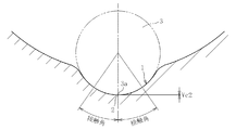
従来の鍛造成型トラックの横断面形状を図10に示し、仕上げ加工トラックの横断面形状を図11に示す。通常の鍛造成型のトラック溝横断面形状は、単純Rを垂直軸に対して投影した形となるため、トラック溝底2側に形成されるVC(Vertical Clearance)(トラック溝1の溝底2とボール3のこの溝底対応部3aとの間の寸法)を大きくすることが出来、VC測定による形状管理が容易となっている。しかしながら、仕上げ加工のトラック溝1の横断面形状は楕円形状であり、トラック溝底2側のVCが小さくなる。すなわち、鍛造成型トラックのVC量をVC1とし、仕上げ加工トラックのVC量をVC2とした場合、VC1>VC2となる。このため、仕上げ加工をしない鍛造仕上げのトラックに仕上げ加工のトラック形状を適用する場合、単純Rの場合より金型や鍛造品の形状管理がし難くなる。
FIG. 10 shows the cross-sectional shape of a conventional forged molding track, and FIG. 11 shows the cross-sectional shape of a finishing track. The track groove cross-sectional shape of a normal forging molding is a shape in which a simple R is projected onto the vertical axis, so that a VC (Vertical Clearance) formed on the
本発明の課題は、鍛造成形トラックと仕上げ加工トラックのボールとの安定した接触状況を確保することでより優れた耐久性を確保し、鍛造金型や製品の品質管理も従来と変わらず容易とするトラック形状を有する固定式等速自在継手を提案する。 The object of the present invention is to secure a stable contact state between the forged molding track and the ball of the finishing track to ensure superior durability, and forging molds and product quality control are as easy as before. We propose a fixed type constant velocity universal joint with a track shape.
本発明の固定式等速自在継手は、内径面にトラック溝を形成した外側継手部材と、外径面にトラック溝を形成した内側継手部材と、外側継手部材のトラック溝とこれに対応する内側継手部材のトラック溝とが協働して形成されるトルク伝達ボールトラックに配設されるトルク伝達ボールと、トルク伝達ボールを保持するケージとを備えた固定式等速自在継手であって、外側継手部材のトラック溝と内側継手部材のトラック溝の少なくとも一方を、冷間鍛造仕上げにより成型し、その横断面形状を、トラック溝底側をゴシックアーチ形状とし、トラック溝開口側を楕円形状とし、かつ、トラック溝の開角側から継手奥側に向かって、前記ゴシックアーチ形状と楕円形状との繋ぎ角度を徐々に小さくしたものである。 The fixed type constant velocity universal joint of the present invention includes an outer joint member having a track groove formed on the inner diameter surface, an inner joint member having a track groove formed on the outer diameter surface, a track groove of the outer joint member, and an inner side corresponding thereto. A fixed type constant velocity universal joint provided with a torque transmission ball disposed on a torque transmission ball track formed in cooperation with a track groove of a joint member, and a cage for holding the torque transmission ball. At least one of the track groove of the joint member and the track groove of the inner joint member is molded by cold forging, and the cross-sectional shape thereof is a gothic arch shape on the track groove bottom side, and the track groove opening side is an elliptical shape. In addition, the connecting angle between the Gothic arch shape and the elliptical shape is gradually reduced from the opening angle side of the track groove toward the joint back side.
本発明の固定式等速自在継手は、球面に近い側(トラック溝開口側)を仕上げ加工トラック溝と同様の楕円形状とすることができる。すなわち、機能上必要なトラック範囲を楕円形状とし、管理上必要なトラック範囲をゴシックアーチ形状とすることになる。 In the fixed type constant velocity universal joint of the present invention, the side close to the spherical surface (track groove opening side) can have an elliptical shape similar to that of the finishing track groove. That is, the track range necessary for the function is an elliptical shape, and the track range necessary for the management is a Gothic arch shape.
トラック溝の開角側(継手開口側)から継手奥側に向かって、ゴシックアーチ形状と楕円形状との繋ぎ角度(繋ぎ位置)を徐々に小さくしているので、継手奥側においても、接触楕円のはみ出しが発生しにくくなる。この場合、継手開口側であるトラック溝の開角側から継手奥側に向けて接触角が徐々に小さくなるように設定できる。 Since the joint angle (joint position) between the Gothic arch shape and the elliptical shape is gradually reduced from the open angle side (joint opening side) of the track groove to the joint back side, the contact ellipse is also on the joint back side. The protrusion is less likely to occur. In this case, the contact angle can be set to gradually decrease from the opening angle side of the track groove on the joint opening side toward the joint back side.
ゴシックアーチ形状と楕円形状との繋ぎ位置を、ボール中心とトラック溝底中心とを結んだ直線を中心に、30°〜45°の範囲で溝開口側に位置するようにしたり、20°〜35°の範囲で溝開口側に位置するようにしたりできる。20°未満では、形状管理のためのVC量が不足し、また、45°を越えれば、45°を超える範囲のトラック面(範囲)が小さく、楕円とすることの影響が小さくなる(有利さが発揮されない)。 The connecting position of the Gothic arch shape and the elliptical shape is located on the groove opening side in the range of 30 ° to 45 ° around the straight line connecting the ball center and the track groove bottom center, or 20 ° to 35 It can be positioned on the groove opening side within a range of °. If it is less than 20 °, the amount of VC for shape management is insufficient, and if it exceeds 45 °, the track surface (range) in the range exceeding 45 ° is small, and the effect of making an ellipse is small (advantage) Is not demonstrated).
外側継手部材における内径面とトラック溝との境界部と、内側継手部材における外径面とトラック溝との境界部とにそれぞれトラックチャンファを形成するとともに、トラックチャンファのトラック溝側に、トラック溝と連結されるアール部を形成したものとできる。また、外側継手部材における内径面とトラック溝との境界部と、内側継手部材における外径面とトラック溝との境界部をアール状のトラックチャンファとすることができる。 A track chamfer is formed at each of the boundary portion between the inner diameter surface and the track groove in the outer joint member and the boundary portion between the outer diameter surface and the track groove in the inner joint member, and the track groove is formed on the track groove side of the track chamfer. A rounded portion to be connected can be formed. Further, the boundary portion between the inner diameter surface and the track groove in the outer joint member and the boundary portion between the outer diameter surface and the track groove in the inner joint member can be a rounded track chamfer.
さらに、外側継手部材の開口縁全周に沿って形成される入口チャンファと、外側継手部材における内径面とトラック溝との境界部のトラックチャンファと、入口チャンファとトラック溝との境界部のトラック入口チャンファとを冷間鍛造仕上げにより形成することができる。 Furthermore, an inlet chamfer formed along the entire circumference of the opening edge of the outer joint member, a track chamfer at the boundary between the inner diameter surface and the track groove in the outer joint member, and a track inlet at the boundary between the inlet chamfer and the track groove The chamfer can be formed by cold forging.
外側継手部材の開口端面乃至開口縁全周に沿って形成される入口チャンファを冷間鍛造仕上げにより形成してもよい。また、外側継手部材のトラック溝とトラック入口チャンファとを同時冷間鍛造仕上げにより形成したり、外側継手部材のトラック溝とトラックチャンファ、及び内側継手部材のトラック溝とトラックチャンファを同時冷間鍛造仕上げによりそれぞれ形成したりすることができる。 The inlet chamfer formed along the opening end face or the entire periphery of the opening edge of the outer joint member may be formed by cold forging. Also, the track groove and the track inlet chamfer of the outer joint member are formed by simultaneous cold forging, or the track groove and the track chamfer of the outer joint member and the track groove and the track chamfer of the inner joint member are simultaneously cold forged. Respectively.
固定式等速自在継手として、トラック溝底が円弧部のみであるバーフィールド型やトラック溝底が円弧部及び直線部とからなるアンダーカットフリー型の固定式等速自在継手であってもよい。 The fixed type constant velocity universal joint may be a bar field type in which the track groove bottom is only an arc portion or an undercut free type fixed constant velocity universal joint in which the track groove bottom is an arc portion and a straight portion.
自動車の駆動軸用の固定式等速自在継手に用いたり、自動車のプロペラシャフト用の固定式等速自在継手に用いたりできる。 It can be used for a fixed type constant velocity universal joint for a drive shaft of an automobile or a fixed type constant velocity universal joint for an automobile propeller shaft.
トルク伝達ボールが10個以下であるのが好ましい。 The number of torque transmitting balls is preferably 10 or less.
本発明の固定式等速自在継手では、機能上必要なトラック範囲を楕円形状とし、管理上必要なトラック範囲をゴシックアーチ形状とすることになり、鍛造金型や製品の品質管理の容易さと、ボールとトラック溝の接触状態の安定化を両立させることが可能となる。しかも、トラック溝における継手奥側の浅い部位においても、接触楕円のはみ出しが発生し難くなり、より高い耐久性を確保することができる。 In the fixed type constant velocity universal joint of the present invention, the track range necessary for the function is an elliptical shape, the track range necessary for the management is a Gothic arch shape, and the quality control of the forging die and product is easy. It is possible to achieve both stabilization of the contact state between the ball and the track groove. In addition, the contact ellipse does not easily protrude even at a shallow portion of the joint in the track groove, and higher durability can be secured.
ゴシックアーチ形状と楕円形状との繋ぎ位置を、ボール中心とトラック溝底中心とを結んだ直線を中心に、20°〜45°の範囲で溝開口側に位置するものでは、形状管理のためのVC量を十分確保でき、機能上必要なトラック面を十分確保できる。 For connecting the Gothic arch shape and the elliptical shape with the straight line connecting the ball center and the track groove bottom center in the range of 20 ° to 45 ° on the groove opening side, A sufficient amount of VC can be secured, and a sufficient track surface necessary for the function can be secured.
外側継手部材の入口チャンファと、外側継手部材のトラックチャンファと、内側継手部材のトラックチャンファと、入口チャンファとトラック溝とのトラック入口チャンファ等を冷間鍛造仕上げすることによって、従来の冷間鍛造後の切削加工や研削加工等を省略することができる。これによって、歩留まりが向上し、固定式等速自在継手の製造コストの低減を図ることができる。 After conventional cold forging by cold forging the inlet chamfer of the outer joint member, the track chamfer of the outer joint member, the track chamfer of the inner joint member, the track chamfer of the inlet chamfer and the track groove, etc. Cutting, grinding, etc. can be omitted. As a result, the yield can be improved and the manufacturing cost of the fixed type constant velocity universal joint can be reduced.
特に、外側継手部材のトラック溝とトラック入口チャンファとを同時冷間鍛造仕上げにより形成したり、外側継手部材のトラック溝とトラックチャンファ、内側継手部材のトラック溝とトラックチャンファを同時冷間鍛造仕上げにより形成したりすることによって生産性の向上を図ることができる。 In particular, the track groove and track chamfer of the outer joint member are formed by simultaneous cold forging finish, the track groove and track chamfer of the outer joint member, and the track groove and track chamfer of the inner joint member by simultaneous cold forging finish. Thus, productivity can be improved.
トルク伝達ボールが10個以下であればよいので、設計自由度が大となって、設計性に優れる。また、種々のタイプの固定式等速自在継手に対応することができる。 Since it is sufficient that the number of the torque transmission balls is 10 or less, the degree of freedom in design is great and the design is excellent. Moreover, it can respond to various types of fixed type constant velocity universal joints.
以下、本発明の実施形態を図面に従って説明する。 Hereinafter, embodiments of the present invention will be described with reference to the drawings.
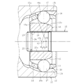
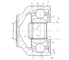
図4は本発明の固定式等速自在継手であるアンダーカットフリータイプの固定式等速自在継手を示している。この固定式等速自在継手は、内球面(内径面)11に複数のトラック溝12が円周方向等間隔に軸方向に沿って形成された外側継手部材13と、外球面(外径面)14に外側継手部材13のトラック溝12と対をなす複数のトラック溝15が円周方向等間隔に軸方向に沿って形成された内側継手部材16と、外側継手部材13のトラック溝12と内側継手部材16のトラック溝15との間に介在してトルクを伝達する複数のボール17と、外側継手部材13の内球面11と内側継手部材16の外球面14との間に介在してボール17を保持するケージ18とを備えている。ケージ18には、ボール17が収容されるポケット18aが周方向に沿って複数配設されている。
FIG. 4 shows an undercut free type fixed type constant velocity universal joint which is a fixed type constant velocity universal joint of the present invention. This fixed type constant velocity universal joint includes an outer
また、外側継手部材13のトラック溝12は、奥側が円弧部12aとされ、開口側が直線部12bとされる。内側継手部材16のトラック溝15は、奥側が直線部15aとされ、開口側が円弧部15bとされる。内側継手部材16のトラック溝15の曲率中心O1および外側継手部材13のトラック溝12の曲率中心O2は、継手中心Oに対して等距離F、Fだけ軸方向に逆向きにオフセットされている。
Further, the
また、内側継手部材16はシャフト嵌入用孔部19が設けられ、このシャフト嵌入用孔部19の内径面に雌スプライン23が形成されている。内側継手部材16のシャフト嵌入用孔部19にシャフト25の端部雄スプライン25aが嵌入され、この端部雄スプライン25aが内側継手部材16の雌スプライン23に嵌合する。なお、端部雄スプライン25aの端部には周方向溝26が設けられ、この周方向溝26に止め輪27が装着されている。
The inner
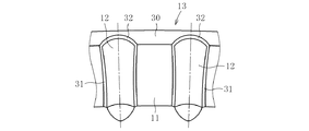
外側継手部材13において、図5に示すように、開口縁全周に沿って形成される入口チャンファ(カップ入口チャンファ)30が形成され、内径面11とトラック溝12との境界部には、トラックチャンファ31が形成され、トラック溝12とカップ入口チャンファ30との境界部にはトラック入口チャンファ32が形成されている。
In the outer
また、内側継手部材16において、外径面14とトラック溝15との境界部とにトラックチャンファ33(図2参照)が形成される。
In the inner
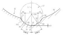
外側継手部材13のトラック溝12の横断面形状を、図1に示すように、トラック溝底側をゴシックアーチ形状とし、トラック溝開口側を楕円形状としている。すなわち、外側継手部材13のトラック溝12は、トラック溝底側に単純アールトラック形状部35を形成するとともに、トラック溝開口側の楕円トラック形状部36,36を備えるものである。外側継手部材13における内径面11とトラック溝12との境界部のトラックチャンファ31は、図1に示すようなアール部31aから構成される。
As shown in FIG. 1, the cross-sectional shape of the
内側継手部材16のトラック溝15の横断面形状も、図2に示すように、トラック溝底側をゴシックアーチ形状とし、トラック溝開口側を楕円形状としている。すなわち、内側継手部材16のトラック溝15は、トラック溝底側に単純アールトラック形状部38を形成するとともに、トラック溝開口側の楕円トラック形状部39,39を備えるものである。内側継手部材16における外径面14とトラック溝15との境界部のトラックチャンファ33は、図2に示すように、テーパ面33aからなり、このトラックチャンファ33とトラック溝15とは小アール部40を介して連設されている。
As shown in FIG. 2, the cross-sectional shape of the
なお、外側継手部材13におけるトラックチャンファ31を図2に示すようなトラックチャンファ33の形状としても、内側継手部材16におけるトラックチャンファ33を図1に示すようなトラックチャンファ31の形状としてもよい。
The
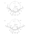
ところで、単純アールトラック形状部35(38)と楕円トラック形状部36(39)との繋ぎ位置22は、図3(a)(b)に示すように、ボール中心Obとトラック溝底中心とを結んだ直線Lを中心に、θ(θ1、θ2)の範囲で溝開口側に位置する。すなわち、図1と図2に示すように、単純アールトラック形状部35(38)は範囲H内に設けられ、楕円トラック形状部36(39)は範囲H1内に設けられる。図3(a)では、そのθをθ1(30°〜45°)とし、図3(b)では、そのθをθ2(20°〜35°)としている。
By the way, as shown in FIGS. 3A and 3B, the connecting
外側継手部材13においては、トラック溝12、入口チャンファ(カップ入口チャンファ)30、トラックチャンファ31、及びトラック入口チャンファ32、開口端面13aが冷間鍛造仕上げにより形成される。特に、外側継手部材13のトラック溝12とトラック入口チャンファ32とを同時冷間鍛造仕上げにより形成し、外側継手部材13のトラック溝12とトラックチャンファ31を同時冷間鍛造仕上げにより形成する。
In the outer
ところで、外側継手部材13の鍛造仕上げには、既設の製造装置(例えば、特開2009−185933号公報に開示された製造装置等)にて行うことができる。この場合、複数の分割パンチのトラック溝形成部の形状を、単純アールトラック形状部35と楕円トラック形状部36,36とを形成することができる形状に変更すればよい。
By the way, forging finishing of the outer
また、内側継手部材16においても、トラック溝15とトラックチャンファ33とは同時冷間鍛造仕上げにより形成する。内側継手部材16の鍛造仕上げには、既設の製造装置(例えば、特開2007−260698号公報に開示された製造装置等)にて行うことができる。この場合、ダイスのトラック溝形成部の形状を、単純アールトラック形状部38と楕円トラック形状部39,39とを形成することができる形状に変更すればよい。
Also in the inner
本発明の固定式等速自在継手は、球面に近い側(トラック溝開口側)を仕上げ加工トラック溝と同様の楕円形状とすることができる。すなわち、機能上必要なトラック範囲を楕円形状とし、管理上必要なトラック範囲をゴシックアーチ形状とすることになる。このため、鍛造金型や製品の品質管理の容易さと、ボール17とトラック溝12(15)の接触状態の安定化を両立させることが可能となる。
In the fixed type constant velocity universal joint of the present invention, the side close to the spherical surface (track groove opening side) can have an elliptical shape similar to that of the finishing track groove. That is, the track range necessary for the function is an elliptical shape, and the track range necessary for the management is a Gothic arch shape. For this reason, it becomes possible to achieve both easy quality control of the forging die and product and stabilization of the contact state between the
また、ゴシックアーチ形状と楕円形状との繋ぎ位置を、ボール中心Obとトラック溝底中心とを結んだ直線を中心に、20°〜45°の範囲で溝開口側に位置する。このため、形状管理のためのVC(Vertical Clearance)量を、図1と図2に示すように、VC3、VC4に示すように、十分確保でき、機能上必要なトラック面を十分確保できる。 Further, the connecting position between the Gothic arch shape and the elliptical shape is located on the groove opening side in the range of 20 ° to 45 ° with the straight line connecting the ball center Ob and the track groove bottom center as the center. Therefore, a VC (Vertical Clearance) amount for shape management can be sufficiently secured as shown in VC3 and VC4 as shown in FIGS. 1 and 2, and a track surface necessary for function can be sufficiently secured.
外側継手部材13の入口チャンファ30と、外側継手部材13のトラックチャンファ31と、外側継手部材13のトラック入口チャンファ32と、内側継手部材16のトラックチャンファ33等を冷間鍛造仕上げすることによって、従来の冷間鍛造後の切削加工や研削加工等を省略することができる。これによって、歩留まりが向上し、固定式等速自在継手の製造コストの低減を図ることができる。
By cold forging the
特に、外側継手部材13のトラック溝12とトラック入口チャンファ32とを同時冷間鍛造仕上げにて形成したり、外側継手部材13のトラック溝12とトラックチャンファ31、及び内側継手部材16のトラック溝17とトラックチャンファ33を同時冷間鍛造仕上げにて形成したりすることによって生産性の向上を図ることができる。
In particular, the
トルク伝達ボールとしては10個以下であればよい。このため、設計自由度が大となって、設計性に優れる。 The torque transmission balls may be 10 or less. For this reason, the degree of design freedom is large and the design is excellent.
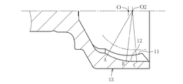
ところで、この種の固定式等速自在継手においては、図6に示すように、外側継手部材13のトラック溝12は、トラック開角側(継手開口側)から継手奥側に向かって徐々に浅くなる。このため、単純アールトラック形状部35(38)と楕円トラック形状部36(39)との繋ぎ位置22が、開角側から継手奥側に沿って同一位置であれば、継手奥側ほど繋ぎ位置22からトラックエッジE(トラック溝と内径面との境界線)(図7と図8参照)までの距離が、継手奥側ほど短くなる。
By the way, in this type of fixed type constant velocity universal joint, as shown in FIG. 6, the
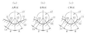
すなわち、図6のA断面(トラック溝12の中心O2とA部とを結ぶ直線に沿って切断されてなる断面)におけるθと、図6のB断面(トラック溝12の中心O2とB部とを結ぶ直線に沿って切断されてなる断面)におけるθと、図6のC断面(トラック溝12の中心O2とC部とを結ぶ直線に沿って切断されてなる断面)におけるθとが、図8(a)(b)(c)では同一である。 That is, θ in the A cross section of FIG. 6 (cross section cut along a straight line connecting the center O2 and A portion of the track groove 12) and the B cross section of FIG. 6 (center O2 and B portion of the track groove 12) Θ in a cross section cut along a straight line connecting the two and the C in FIG. 6 (cross section cut along a straight line connecting the center O2 and the C portion of the track groove 12) in FIG. 8 (a), (b) and (c) are the same.
この場合、図8(a)に示すように、A断面での繋ぎ位置22からトラックエッジEまでの距離をLaとし、図8(b)に示すように、B断面での繋ぎ位置22からトラックエッジEまでの距離をLbとし、図8(c)に示すように、C断面での繋ぎ位置22からトラックエッジEまでの距離をLcとする。この場合、La<Lb<Lcとなる。このため、想像以上の大きなトルクを負荷した場合、接触楕円がはみ出して寿命が低下する。
In this case, as shown in FIG. 8A, the distance from the
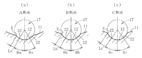
そこで、本発明では、トラック溝の開角側(継手開口側)から継手奥側に向かって、前記ゴシックアーチ形状と楕円形状との繋ぎ角度θ(θa、θb、θc)を図7に示すように、徐々に小さくしている。このように、設定すれば、A断面での繋ぎ位置22からトラックエッジEまでの距離がLa´(図7(a)参照)とし、B断面での繋ぎ位置22からトラックエッジEまでの距離がLb´(図7(b)参照)とし、C断面での繋ぎ位置22からトラックエッジEまでの距離がLc´(図7(c)参照)となる。この場合、La<La´となり、Lb<Lb´となり、Lc<Lc´となる。
Therefore, in the present invention, the connecting angle θ (θa, θb, θc) between the Gothic arch shape and the elliptical shape is shown in FIG. 7 from the opening angle side (joint opening side) of the track groove to the joint back side. It is gradually getting smaller. Thus, if set, the distance from the
これによって、トラック溝における継手奥側の浅い部位においても、接触楕円のはみ出しが発生し難くなり、より高い耐久性を確保することができる。この場合、接触角として、継手開口側から継手奥側に沿って変化しないものであっても、継手開口側から継手奥側に沿って徐々に小さくなるものであってもよい。 This makes it difficult for the contact ellipse to protrude even in a shallow part of the track groove on the deeper side of the joint, thereby ensuring higher durability. In this case, the contact angle may not change from the joint opening side to the joint back side, or may gradually decrease from the joint opening side to the joint back side.
次に、図9はバーフィールドタイプの固定式等速自在継手であって、この固定式等速自在継手は、内径面41に複数のトラック溝42が円周方向等間隔に軸方向に沿って形成された外側継手部材43と、外径面44に外側継手部材43のトラック溝42と対をなす複数のトラック溝45が円周方向等間隔に軸方向に沿って形成された内側継手部材46と、外側継手部材43のトラック溝42と内側継手部材46のトラック溝45とが協働して形成されるボールトラックにそれぞれ配されたトルク伝達ボール47と、外側継手部材43の内径面41と内側継手部材46の外径面44との間に介在してボール47を保持するケージ48とを備えている。
Next, FIG. 9 shows a bar field type fixed type constant velocity universal joint. This fixed type constant velocity universal joint has a plurality of
この場合も、トラック溝42、45は図1と図2に示すように、トラック溝底側に単純アールトラック形状部35、38を形成するとともに、トラック溝開口側の楕円トラック形状部36,36、39,39を備えるものである。しかも、トラック溝の開角側から継手奥側に向かって、前記ゴシックアーチ形状と楕円形状との繋ぎ角度を徐々に小さくする。
Also in this case, as shown in FIGS. 1 and 2, the
さらには、外側継手部材43において、開口縁全周に沿って形成される入口チャンファ(カップ入口チャンファ)30が形成され、内径面41とトラック溝42との境界部には、トラックチャンファが形成され、トラック溝42とカップ入口チャンファ30との境界部にはトラック入口チャンファが形成されている。また、内側継手部材46において、外径面44とトラック溝45との境界部とにトラックチャンファが形成される。
Furthermore, an inlet chamfer (cup inlet chamfer) 30 formed along the entire periphery of the opening edge is formed in the outer
この場合も、トラック溝42、入口チャンファ(カップ入口チャンファ)、トラックチャンファ、及びトラック入口チャンファ、外側継手部材43の開口端面43aが冷間鍛造仕上げにより形成される。特に、外側継手部材43のトラック溝42とトラック入口チャンファとを同時冷間鍛造仕上げにより形成し、外側継手部材43のトラック溝12とトラックチャンファ、内側継手部材46のトラック溝45とトラックチャンファを同時冷間鍛造仕上げにより形成する。
Also in this case, the
このようなバーフィールドタイプの固定式等速自在継手であっても、前記図1に示すアンダーカットフリータイプの固定式等速自在継手と同様の作用効果を奏する。このため、本発明の固定式等速自在継手は、自動車の駆動軸用の固定式等速自在継手に用いたり、自動車のプロペラシャフト用の固定式等速自在継手に用いたりできる。 Even such a barfield type fixed type constant velocity universal joint has the same effects as the undercut free type fixed type constant velocity universal joint shown in FIG. For this reason, the fixed type constant velocity universal joint of the present invention can be used for a fixed type constant velocity universal joint for a drive shaft of an automobile or a fixed type constant velocity universal joint for a propeller shaft of an automobile.
以上、本発明の実施形態につき説明したが、本発明は前記実施形態に限定されることなく種々の変形が可能であって、例えば、前記実施形態では、外側継手部材及び内側継手部材の各トラック溝を冷間鍛造仕上げにて形成していたが、外側継手部材及び内側継手部材のいずれか一方のみのトラック溝を冷間鍛造仕上げにて形成したものであってもよい。チャンファのアール部の曲率半径としては、トラック溝と内径面(又は外径面)とが滑らかに連続するものであれば種々変更することができる。また、図7のθa、θb、θc等の変位量は、トラック溝における継手奥側の浅い部位においても接触楕円のはみ出しが発生しにくくなる範囲で種々変更できる。 As described above, the embodiment of the present invention has been described. However, the present invention is not limited to the above-described embodiment, and various modifications are possible. For example, in the above-described embodiment, each track of the outer joint member and the inner joint member Although the groove is formed by cold forging, the track groove of only one of the outer joint member and the inner joint member may be formed by cold forging. The radius of curvature of the round portion of the chamfer can be variously changed as long as the track groove and the inner diameter surface (or outer diameter surface) are smoothly continuous. Further, the displacement amounts such as θa, θb, and θc in FIG. 7 can be variously changed within a range in which the protrusion of the contact ellipse hardly occurs even in a shallow portion of the track groove on the back side of the joint.
11 内径面
12 トラック溝
13 外側継手部材
14 外径面
15 トラック溝
16 内側継手部材
17 トルク伝達ボール
18 ケージ
30 カップ入口チャンファ
31 トラックチャンファ
32 トラック入口チャンファ
33 トラックチャンファ
41 内球面(内径面)
42、45 トラック溝
43 外側継手部材
44 外球面
46 内側継手部材
47 ボール
48 ケージ
11
42, 45
Claims (15)
外側継手部材のトラック溝と内側継手部材のトラック溝の少なくとも一方を、冷間鍛造仕上げにより成型し、その横断面形状を、トラック溝底側をゴシックアーチ形状とし、トラック溝開口側を楕円形状とし、かつ、トラック溝の開角側から継手奥側に向かって、前記ゴシックアーチ形状と楕円形状との繋ぎ角度を徐々に小さくしたことを特徴とする固定式等速自在継手。 The outer joint member having a track groove formed on the inner diameter surface, the inner joint member having a track groove formed on the outer diameter surface, the track groove of the outer joint member, and the track groove of the corresponding inner joint member cooperated. A fixed type constant velocity universal joint comprising a torque transmission ball disposed on a formed torque transmission ball track and a cage for holding the torque transmission ball,
At least one of the track groove of the outer joint member and the track groove of the inner joint member is molded by cold forging, and the cross-sectional shape thereof is a gothic arch shape on the track groove bottom side and an elliptical shape on the track groove opening side. A fixed type constant velocity universal joint characterized in that the connecting angle between the Gothic arch shape and the elliptical shape is gradually reduced from the opening angle side of the track groove to the joint back side.
Priority Applications (5)
| Application Number | Priority Date | Filing Date | Title |
|---|---|---|---|
| JP2010111251A JP5566769B2 (en) | 2010-05-13 | 2010-05-13 | Fixed constant velocity universal joint |
| EP11765392.3A EP2554867B1 (en) | 2010-04-02 | 2011-03-23 | Constant velocity universal joint |
| CN201180016862.8A CN102822548B (en) | 2010-04-02 | 2011-03-23 | Constant velocity universal joint |
| PCT/JP2011/056889 WO2011125491A1 (en) | 2010-04-02 | 2011-03-23 | Constant velocity universal joint |
| US13/637,093 US8684850B2 (en) | 2010-04-02 | 2011-03-23 | Constant velocity universal joint |
Applications Claiming Priority (1)
| Application Number | Priority Date | Filing Date | Title |
|---|---|---|---|
| JP2010111251A JP5566769B2 (en) | 2010-05-13 | 2010-05-13 | Fixed constant velocity universal joint |
Publications (2)
| Publication Number | Publication Date |
|---|---|
| JP2011237018A true JP2011237018A (en) | 2011-11-24 |
| JP5566769B2 JP5566769B2 (en) | 2014-08-06 |
Family
ID=45325216
Family Applications (1)
| Application Number | Title | Priority Date | Filing Date |
|---|---|---|---|
| JP2010111251A Expired - Fee Related JP5566769B2 (en) | 2010-04-02 | 2010-05-13 | Fixed constant velocity universal joint |
Country Status (1)
| Country | Link |
|---|---|
| JP (1) | JP5566769B2 (en) |
Cited By (3)
| Publication number | Priority date | Publication date | Assignee | Title |
|---|---|---|---|---|
| JP2013053690A (en) * | 2011-09-05 | 2013-03-21 | Ntn Corp | Fixed type constant velocity universal joint |
| EP3073140A4 (en) * | 2013-11-22 | 2017-08-02 | NTN Corporation | Stationary constant velocity universal joint |
| EP4641039A4 (en) * | 2022-12-12 | 2026-04-01 | Ntn Toyo Bearing Co Ltd | FIXED UNIVERSAL CONVERTER JOINT |
Families Citing this family (1)
| Publication number | Priority date | Publication date | Assignee | Title |
|---|---|---|---|---|
| KR20160111127A (en) * | 2015-03-16 | 2016-09-26 | 이래오토모티브시스템 주식회사 | Constant Velocity Joint for vehicle |
Citations (4)
| Publication number | Priority date | Publication date | Assignee | Title |
|---|---|---|---|---|
| JP2007139094A (en) * | 2005-11-18 | 2007-06-07 | Ntn Corp | Constant speed universal joint |
| JP2007255707A (en) * | 2006-02-24 | 2007-10-04 | Jtekt Corp | Constant velocity joint |
| JP2009079684A (en) * | 2007-09-26 | 2009-04-16 | Ntn Corp | Fixed type constant velocity universal joint |
| JP2009185933A (en) * | 2008-02-07 | 2009-08-20 | Ntn Corp | CVJ, CVJ outer ring manufacturing method and manufacturing apparatus thereof |
-
2010
- 2010-05-13 JP JP2010111251A patent/JP5566769B2/en not_active Expired - Fee Related
Patent Citations (4)
| Publication number | Priority date | Publication date | Assignee | Title |
|---|---|---|---|---|
| JP2007139094A (en) * | 2005-11-18 | 2007-06-07 | Ntn Corp | Constant speed universal joint |
| JP2007255707A (en) * | 2006-02-24 | 2007-10-04 | Jtekt Corp | Constant velocity joint |
| JP2009079684A (en) * | 2007-09-26 | 2009-04-16 | Ntn Corp | Fixed type constant velocity universal joint |
| JP2009185933A (en) * | 2008-02-07 | 2009-08-20 | Ntn Corp | CVJ, CVJ outer ring manufacturing method and manufacturing apparatus thereof |
Cited By (3)
| Publication number | Priority date | Publication date | Assignee | Title |
|---|---|---|---|---|
| JP2013053690A (en) * | 2011-09-05 | 2013-03-21 | Ntn Corp | Fixed type constant velocity universal joint |
| EP3073140A4 (en) * | 2013-11-22 | 2017-08-02 | NTN Corporation | Stationary constant velocity universal joint |
| EP4641039A4 (en) * | 2022-12-12 | 2026-04-01 | Ntn Toyo Bearing Co Ltd | FIXED UNIVERSAL CONVERTER JOINT |
Also Published As
| Publication number | Publication date |
|---|---|
| JP5566769B2 (en) | 2014-08-06 |
Similar Documents
| Publication | Publication Date | Title |
|---|---|---|
| JP5394078B2 (en) | Outer joint member of fixed type constant velocity universal joint | |
| WO2011125491A1 (en) | Constant velocity universal joint | |
| JP5566769B2 (en) | Fixed constant velocity universal joint | |
| JP6552848B2 (en) | Closed forging method of trunnion for universal joint and trunnion for universal joint | |
| JP5784423B2 (en) | Fixed constant velocity universal joint | |
| JP2012072865A (en) | Fixed constant velocity universal joint | |
| JP5670084B2 (en) | Constant velocity universal joint | |
| JP5502228B2 (en) | Outer joint member of fixed type constant velocity universal joint | |
| JP5921918B2 (en) | Method for manufacturing outer joint member for constant velocity universal joint | |
| WO2024127915A1 (en) | Fixed-type universal joint | |
| JP2024135074A (en) | Constant velocity universal joint | |
| JP2007139094A (en) | Constant speed universal joint | |
| JP2004332817A (en) | Fixed type constant speed universal joint | |
| WO2017010204A1 (en) | Forging method for inner joint member of constant-velocity universal joint | |
| JP6389034B2 (en) | Fixed constant velocity universal joint | |
| JP6591223B2 (en) | Fixed constant velocity universal joint | |
| JP4515377B2 (en) | Fixed type constant velocity universal joint | |
| JP2010001951A (en) | Outer member for constant velocity universal joint, and method of manufacturing thereof | |
| JP2010019345A (en) | Fixed type constant velocity universal joint | |
| WO2018123394A1 (en) | Fixed-type constant-velocity universal joint | |
| EP2564950A2 (en) | Outer joint member for constant velocity universal joint and method for manufacturing the same | |
| JP2025138068A (en) | Fixed constant velocity universal joint | |
| JP2009138906A (en) | Fixed type constant velocity universal joint | |
| JP2008101656A (en) | Fixed type constant velocity universal joint | |
| JP2007231975A (en) | Fixed type constant velocity universal joint |
Legal Events
| Date | Code | Title | Description |
|---|---|---|---|
| A621 | Written request for application examination |
Free format text: JAPANESE INTERMEDIATE CODE: A621 Effective date: 20130426 |
|
| A131 | Notification of reasons for refusal |
Free format text: JAPANESE INTERMEDIATE CODE: A131 Effective date: 20131127 |
|
| A521 | Request for written amendment filed |
Free format text: JAPANESE INTERMEDIATE CODE: A523 Effective date: 20140114 |
|
| A131 | Notification of reasons for refusal |
Free format text: JAPANESE INTERMEDIATE CODE: A131 Effective date: 20140326 |
|
| A521 | Request for written amendment filed |
Free format text: JAPANESE INTERMEDIATE CODE: A523 Effective date: 20140509 |
|
| TRDD | Decision of grant or rejection written | ||
| A01 | Written decision to grant a patent or to grant a registration (utility model) |
Free format text: JAPANESE INTERMEDIATE CODE: A01 Effective date: 20140530 |
|
| A61 | First payment of annual fees (during grant procedure) |
Free format text: JAPANESE INTERMEDIATE CODE: A61 Effective date: 20140618 |
|
| R150 | Certificate of patent or registration of utility model |
Ref document number: 5566769 Country of ref document: JP Free format text: JAPANESE INTERMEDIATE CODE: R150 |
|
| R250 | Receipt of annual fees |
Free format text: JAPANESE INTERMEDIATE CODE: R250 |
|
| R250 | Receipt of annual fees |
Free format text: JAPANESE INTERMEDIATE CODE: R250 |
|
| R250 | Receipt of annual fees |
Free format text: JAPANESE INTERMEDIATE CODE: R250 |
|
| R250 | Receipt of annual fees |
Free format text: JAPANESE INTERMEDIATE CODE: R250 |
|
| R250 | Receipt of annual fees |
Free format text: JAPANESE INTERMEDIATE CODE: R250 |
|
| LAPS | Cancellation because of no payment of annual fees |