JP2011237123A - High frequency cooking device - Google Patents
High frequency cooking device Download PDFInfo
- Publication number
- JP2011237123A JP2011237123A JP2010108965A JP2010108965A JP2011237123A JP 2011237123 A JP2011237123 A JP 2011237123A JP 2010108965 A JP2010108965 A JP 2010108965A JP 2010108965 A JP2010108965 A JP 2010108965A JP 2011237123 A JP2011237123 A JP 2011237123A
- Authority
- JP
- Japan
- Prior art keywords
- temperature sensor
- infrared temperature
- antenna
- steam
- heating chamber
- Prior art date
- Legal status (The legal status is an assumption and is not a legal conclusion. Google has not performed a legal analysis and makes no representation as to the accuracy of the status listed.)
- Granted
Links
Images


Landscapes
- Electric Ovens (AREA)
- Constitution Of High-Frequency Heating (AREA)
Abstract
【課題】加熱室に蒸気が満ちている状態でも物体温度を赤外線温度センサで測定することが可能な高周波調理装置を提供する。
【解決手段】高周波調理装置1の加熱室20の底部には誘電体製の底トレイ33がはめ込まれる。底トレイ33の下は高周波が導入されるアンテナ室32として構成される。アンテナ室32の外には、アンテナ室32の空間を通して底トレイ33に載置された物体の温度を測定する赤外線温度センサ60が配置される。赤外線温度センサ60はアンテナ室32の底部に形成された貫通孔32aを通じて温度測定を行う。アンテナ室32に配置された回転アンテナ34には、赤外線温度センサ60の視野を通過する開口部34aが形成されている。
【選択図】図3An object of the present invention is to provide a high-frequency cooking apparatus capable of measuring an object temperature with an infrared temperature sensor even when a heating chamber is full of steam.
A dielectric bottom tray (33) is fitted to the bottom of a heating chamber (20) of a high frequency cooking device (1). Below the bottom tray 33 is configured as an antenna chamber 32 into which high frequency is introduced. Outside the antenna chamber 32, an infrared temperature sensor 60 that measures the temperature of an object placed on the bottom tray 33 through the space of the antenna chamber 32 is disposed. The infrared temperature sensor 60 measures temperature through a through hole 32 a formed in the bottom of the antenna chamber 32. An opening 34 a that passes through the field of view of the infrared temperature sensor 60 is formed in the rotating antenna 34 disposed in the antenna chamber 32.
[Selection] Figure 3
Description
本発明は高周波調理装置に関する。 The present invention relates to a high-frequency cooking apparatus.
高周波(マイクロ波)で食品の分子を振動させ、それにより食品を内部から加熱する高周波調理装置は、一般的には「電子レンジ」という呼称で親しまれ、家庭の必需品となっている。 A high-frequency cooking apparatus that vibrates food molecules with high frequency (microwave) and thereby heats the food from the inside is generally known as “microwave oven” and has become a household necessity.
最近の高周波調理装置では、加熱中の食品の温度を赤外線温度センサで監視して加熱を制御するものが多くなっている。その例を特許文献1に見ることができる。 In recent high-frequency cooking apparatuses, an apparatus that controls the heating by monitoring the temperature of the food being heated with an infrared temperature sensor is increasing. An example of this can be seen in US Pat.
特許文献1記載の高周波調理装置は、ターンテーブルレスの食品載置台に載置された食品の温度情報を、加熱室の上方に配置された赤外線温度センサで検出している。また、食品載置台の温度情報を熱電対などの接触式温度センサで検出している。
The high-frequency cooking device described in
赤外線温度センサで温度を測定する場合、測定対象物との間に障害物が存在すると測定精度が落ちてしまう。オーブン形式の調理装置では、食品から発生する蒸気や、蒸気調理の際の蒸気が障害物となる。特許文献1記載の装置のように食品から赤外線温度センサまでの距離が長いと、赤外線温度センサは食品との間に存在する蒸気の温度を測定してしまい、食品の温度を正確に測定することができなくなる。このことは、加熱室に蒸気を導入して蒸気調理を行う調理装置では特に深刻な問題となる。
When measuring the temperature with an infrared temperature sensor, if there is an obstacle between the object to be measured, the measurement accuracy is lowered. In an oven-type cooking apparatus, steam generated from food or steam during steam cooking is an obstacle. When the distance from the food to the infrared temperature sensor is long as in the device described in
本発明は上記の点に鑑みなされたものであり、加熱室に蒸気が満ちている状態でも物体温度を赤外線温度センサで測定することが可能な高周波調理装置を提供することを目的とする。 The present invention has been made in view of the above points, and an object thereof is to provide a high-frequency cooking apparatus capable of measuring an object temperature with an infrared temperature sensor even in a state where steam is filled in a heating chamber.
本発明の好ましい実施形態によれば、高周波調理装置は加熱室内に蒸気を導入する調理モードを備え、前記加熱室の底部に誘電体製の底トレイがはめ込まれ、前記底トレイの下は高周波が導入されるアンテナ室として構成されるとともに、前記アンテナ室の空間を通して前記底トレイに載置された物体の温度を測定する赤外線温度センサが配置される。 According to a preferred embodiment of the present invention, the high-frequency cooking apparatus has a cooking mode for introducing steam into the heating chamber, and a bottom tray made of a dielectric material is fitted in the bottom of the heating chamber, and a high frequency is below the bottom tray. An infrared temperature sensor configured to measure the temperature of an object placed on the bottom tray through the space of the antenna chamber is arranged while being configured as an antenna chamber to be introduced.
本発明の好ましい実施形態によれば、蒸気構成の高周波調理装置において、前記赤外線温度センサは前記アンテナ室の外に配置され、前記アンテナ室の底部に形成された貫通孔を通じて温度測定を行う。 According to a preferred embodiment of the present invention, in the high-frequency cooking apparatus having a steam configuration, the infrared temperature sensor is disposed outside the antenna chamber and measures temperature through a through-hole formed in the bottom of the antenna chamber.
本発明の好ましい実施形態によれば、蒸気構成の高周波調理装置において、前記貫通孔は高周波の漏洩を防ぐ大きさのものである。 According to a preferred embodiment of the present invention, in the high-frequency cooking apparatus having a steam configuration, the through hole is of a size that prevents high-frequency leakage.
本発明の好ましい実施形態によれば、蒸気構成の高周波調理装置において、前記アンテナ室に配置された回転アンテナには、前記赤外線温度センサの視野を通過する開口部が形成されている。 According to a preferred embodiment of the present invention, in the high-frequency cooking apparatus having a steam configuration, the rotating antenna disposed in the antenna chamber has an opening that passes through the visual field of the infrared temperature sensor.
本発明の好ましい実施形態によれば、蒸気構成の高周波調理装置において、前記回転アンテナは、前記開口部が前記赤外線温度センサの視野に重なる位置で回転停止状態となる。 According to a preferred embodiment of the present invention, in the high-frequency cooking apparatus having a steam configuration, the rotating antenna is in a rotation stopped state at a position where the opening overlaps the visual field of the infrared temperature sensor.
本発明の好ましい実施形態によれば、蒸気構成の高周波調理装置において、前記底トレイには、前記赤外線温度センサによる温度検知位置に目印がつけられている。 According to a preferred embodiment of the present invention, in the high-frequency cooking apparatus having a steam configuration, the bottom tray is marked with a temperature detection position by the infrared temperature sensor.
本発明の好ましい実施形態によれば、蒸気構成の高周波調理装置において、前記底トレイには、少なくとも前記赤外線温度センサによる温度検知位置に撥水処理が施されている。 According to a preferred embodiment of the present invention, in the high-frequency cooking apparatus having a steam configuration, the bottom tray is subjected to water repellent treatment at least at a temperature detection position by the infrared temperature sensor.
本発明の好ましい実施形態によれば、蒸気構成の高周波調理装置において、前記底トレイは、少なくとも前記赤外線温度センサによる温度検知位置に傾斜が形成されている。 According to a preferred embodiment of the present invention, in the high-frequency cooking apparatus having a steam configuration, the bottom tray is inclined at least at a temperature detection position by the infrared temperature sensor.
本発明の好ましい実施形態によれば、蒸気構成の高周波調理装置において、前記底トレイは、前記赤外線温度センサによる温度検知位置が周囲よりも高く形成されている。 According to a preferred embodiment of the present invention, in the high-frequency cooking apparatus having a steam configuration, the bottom tray is formed such that the temperature detection position by the infrared temperature sensor is higher than the surroundings.
本発明によると、赤外線温度センサは加熱室内部から底トレイで仕切られており、底トレイに載置された物体までの空間に蒸気が入り込まないから、加熱室が蒸気で満たされている状況下でも、トレイに載置された物体の温度を正確に測定することができる。また赤外線温度センサは、温度を測定する物体までの距離が一定となるので、測定誤差を小さくすることができる。 According to the present invention, since the infrared temperature sensor is partitioned from the inside of the heating chamber by the bottom tray, and steam does not enter the space to the object placed on the bottom tray, the heating chamber is filled with steam. However, the temperature of the object placed on the tray can be accurately measured. Moreover, since the distance to the object whose temperature is measured is constant, the infrared temperature sensor can reduce measurement errors.
以下、図に基づき本発明の実施形態である高周波調理装置1の構造を説明する。図1において、紙面の上下は高周波調理装置1の上下に一致する。また紙面左側が高周波調理装置1の左側、紙面右側が高周波調理装置1の右側であるものとする。
Hereinafter, the structure of the high
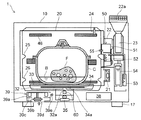
高周波調理装置1は直方体形状の板金製構造体からなる筐体10を備える。筐体10の内部には一回り小さな直方体形状の板金製構造体からなる加熱室20が設けられる。加熱室20は筐体10の正面側が開口部となっている。筐体10の正面には加熱室20の開口部を開閉する板金製の扉11が設けられる。扉11は下部を支点として垂直面内で回動するものであり、上部のハンドル12を握って手前に引くことにより、図3に示す垂直な全閉位置から水平な全開位置へと90°姿勢変換させることができる。
The high
扉11には加熱室20の内部を見通す窓13が形成される。窓13にはパンチングメタルを2枚のガラス板で挟んだドアスクリーン14がはめ込まれ、透視性を保ちつつ電波漏洩が防がれるようになっている。扉11にはドアスクリーン14以外にも電波漏洩防止対策が施され、加熱室との間には気体漏洩を防ぐガスケットが配置され、また閉鎖状態を保つ附勢装置またはロック装置が設けられるが、それらはいずれも周知技術なので、詳細説明は省略する。
The
調理中の食材から発生した蒸気や、調理に用いる蒸気が扉11の内面に結露することがある。結露水が滴り落ちて加熱調理器1の設置場所を濡らさないように、扉11の下には露受け15が配置されている。
Steam generated from ingredients during cooking or steam used for cooking may condense on the inner surface of the
筐体10には、扉11の右側の部分に操作部16が形成される。筐体10の一部を構成する操作部カバー16aには、操作インターフェースとして、一群の操作キー16bやダイヤル16cが配置されている。操作キー16bの上方には表示装置16dが配置されている。
An
筐体10は脚部17によってテーブルや台の上に支持される。脚部17は正面側と背面側の左右2箇所ずつに設けられ、4点支持を形成する。
The
続いて高周波調理装置1の内部構造を説明する。加熱室20の右側の側壁(以下「右側壁」と称する)の外側に給気ファン21が設けられる。給気ファン21は加熱室20の右側壁に形成された図示しない給気口を通じて加熱室20に空気を送り込む。
Next, the internal structure of the high
加熱室20の右側壁の外側には排気ダクト22が設けられる。排気ダクト22の一端は加熱室20の右側壁に形成された図示しない排気口に接続される。排気ダクト22の内部には、前記排気口から少し入り込んだ位置に、湿度センサ71(図5参照)が配置される。
An
排気ダクト22の吹出口22aは筐体10の天板の上に顔を出す。排気ダクト22にはその中に空気を送り込む排気希釈ファン23が接続されている。排気希釈ファン23が排気ダクト22に空気を送り込むと、吹出口22aから機外に吹き出す空気流が生じる。その空気流により加熱室20の中の気体が吸い出され、空気流により希釈されて、吹出口22aから排出される。
The
加熱室20の天井部には、サーミスタからなる温度センサ24が配置される。また加熱室20の右側壁と左側壁には、互いに同じ高さで向き合うトレイ受けが上下2組形成される。上段トレイ受け25も下段トレイ受け26も、右側壁または左側壁から突き出すうね状の突部からなる。突部は加熱室20の奥行きの方向に水平に延びる。
A
食品は、上段トレイ受け25または下段トレイ受け26が支えるトレイまたはラック(図示せず)に支持される。但し、食品が大型である場合とか、鍋のような容器に入れられている場合、また調理用の皿に載せられている場合には、後述する底トレイの上に載置されることもある。
The food is supported by a tray or rack (not shown) supported by the
高周波調理装置1は、高周波による加熱、熱風による加熱、蒸気による加熱、及びそれらを混合した加熱が可能となっている。続いて、各加熱手段の構成を説明する。
The high-
加熱室20の底部と筐体10の底部の間の空間には、マグネトロン30と、マグネトロン30が生成した高周波を加熱室20に供給する導波管31が配置される。導波管31は加熱室20の底部の下に広がるアンテナ室32に接続する。加熱室20の底部にはガラスやセラミックなどの誘電体からなる底トレイ33がはめ込まれる。底トレイ33はアンテナ室32を加熱室20から隔てるものであって、加熱室20にとっては底板となり、アンテナ室32にとっては天井板となる。
In the space between the bottom of the
アンテナ室32には回転アンテナ34が配置される。回転アンテナ34はアンテナモータ35の軸35aの上端に取り付けられており、アンテナモータ35により連続回転しつつ加熱室20内の高周波の分布をコントロールする。軸35aにはスイッチカム36が固定され、スイッチカム36には回転位置検知スイッチ37が組み合わせられて、回転アンテナ34の回転位置を知ることができるようになっている。
A rotating
加熱室20の底部と筐体10の底部の間の空間に電装部品収容部38が設けられ、その中の制御基板に高周波駆動電源72(図5参照)が装着される。高周波駆動電源72もマグネトロン30も高周波加熱時発熱部品、すなわち高周波発振の際かなりの発熱を伴う部品なので、これらを強制空冷する冷却ファン39が筐体10の底部の上に設置される。
An electrical
冷却ファン39は、ファンケーシング39aと、竪軸の冷却ファンモータ39bと、冷却ファンモータ39bの軸の上端に固定されたシロッコファン39cにより構成される。冷却ファンモータ39bを駆動してシロッコファン39cを回転させると、筐体10の底部に形成された吸気口39d(複数の小孔の集合よりなる)から外部の空気が吸い込まれ、その空気はファンケーシング39aの吐出口39eから水平方向に勢いよく吐出されて高周波加熱時発熱部品を空冷する。
The cooling
熱風による加熱は、加熱室20の奥の壁の外側に設けられたコンベクションヒータユニット40によって実現される。コンベクションヒータユニット40を構成するのは、加熱室20の奥の壁の外面に固定された皿形の断熱ファンケーシング41と、断熱ファンケーシング41と加熱室20の奥の壁で囲まれた空間に配置されるコンベクションファン42と、コンベクションファン42を回転させるコンベクションモータ43と、コンベクションファン42の外周を囲む環状のコンベクションヒータ44である。
Heating with hot air is realized by a
コンベクションファン42は遠心ファンであって、加熱室20の奥の壁の中央に形成された吸気口45から加熱室20の内部の空気を吸い込み、それを外周方向に吐出して、吸気口45を囲む形で加熱室20の奥の壁の計6箇所に形成された噴気口46より加熱室20に噴出させる。コンベクションヒータ44に通電しておけば、コンベクションファン42から吐出される空気が加熱され、噴気口46から熱風が噴き出すことになる。なお吸気口45も噴気口46も、複数の小孔の集合よりなる。
The
蒸気による加熱を実現するのは、加熱室20の右側壁の外側に設置された蒸気発生装置50である。蒸気発生装置50は飽和蒸気または過熱蒸気を発生することが可能である。
It is the
蒸気発生装置50は、正面から見て左右方向に偏平となったハウジング51を有する。ハウジング51の内部にはシーズヒータからなる蒸気発生ヒータ52が設けられている。
The
ハウジング51には、給水ポンプ53により給水タンク54の水が供給される。またハウジング51には、内部で発生した蒸気を加熱室20に吹き込む水平な蒸気噴出口55が形成されている。
The
アンテナ室32の底部には貫通孔32aが形成される。そしてアンテナ室32の下には、貫通孔32aを通じて上方に存在する物体の温度測定を行う赤外線温度センサ60が固定される。貫通孔32aは、アンテナ室32からの高周波の漏洩を防ぐことができる大きさとされる。
A through
赤外線温度センサ60は、底トレイ33の中心に比較的近い箇所に配置される。この箇所は回転アンテナ34の中心に比較的近い位置でもある。回転アンテナ34には、図4に示す通り、赤外線温度センサ60の視野を通過する開口部34aが形成されている。回転アンテナ34には、開口部34aの他にも、より小型の開口部34bや切り欠き34cが形成されている。開口部34bと切り欠き34cは高周波が所定パターンで分配されるようにするためのものである。ちなみに回転アンテナ34は、回転状態から回転を停止する場合、必ず開口部34aが赤外線温度センサ60の視野に重なる位置で停止状態となるように構成されている。
The
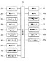
高周波調理装置1の制御システムは図5に示す構成となっている。高周波調理装置1全体の制御を行う制御装置70はマイクロコンピュータを中核として構成され、様々な構成要素から出力信号を受け取り、また様々な構成要素に対し制御信号を出力する。
The control system of the high
制御装置70に信号を出力する構成要素には、既出の操作部16(表示部16dを除く)、温度センサ24、赤外線温度センサ60、及び湿度センサ71の他、次のものが含まれる。すなわち扉11が開いた状態にあるか閉じた状態にあるかを検知する扉開閉センサ11a、蒸気発生装置50の中の水位を測定する水位センサ50a、及び給水タンク54の中の水位を測定するタンク水位センサ54aである。
The components that output a signal to the
制御装置30から制御信号を受けて動作を行う構成要素には、既出の表示部16d、給気ファン22、排気希釈ファン23、アンテナモータ35、冷却ファン39、コンベクションモータ43、コンベクションヒータ44、蒸気発生ヒータ52、給水ポンプ53、及び高周波駆動電源71の他、蒸気発生装置50の中に蒸気発生ヒータ52とは別に設けられた蒸気昇温ヒータ73が含まれる。
Constituent elements that operate in response to a control signal from the
続いて高周波調理装置1の動作を説明する。まず扉11を開け、加熱室20の中に被加熱物である食品を入れる。そして扉15を閉じ、操作部16で調理モードその他の条件を入力して調理を開始する。
Then, operation | movement of the high
高周波加熱モードでは、高周波駆動電源72、アンテナモータ35、給気ファン22、冷却ファン39、及び排気希釈ファン23がONになる。高周波駆動電源72がマグネトロン30を発振させることにより高周波が発生し、発生した高周波は導波管31を通じてアンテナ室32に入る。アンテナ室32に入った高周波はアンテナ34に受信された後、底トレイ33を通じて加熱室20に放射される。そして加熱室20内の食品を加熱する。給気ファン22が加熱室20に新鮮な空気を供給することにより、食品から発生する蒸気を含んだ加熱室20内の空気は排気ダクト22に押し出され、排気希釈ファン23の作用で希釈された後、吹出口22aから機外に排出される。
In the high frequency heating mode, the high frequency driving
熱風加熱モードでは、給気ファン22がOFF、排気希釈ファン23がONの状態で、コンベクションモータ43とコンベクションヒータ44がONになる。コンベクションモータ43によって回転せしめられるコンベクションファン42が給気口45から加熱室20の内部の空気を吸い込み、それを外周方向に吐出する。コンベクションファン42から吐出された空気はコンベクションヒータ44で加熱されて熱風となり、噴気口46より加熱室20に噴き出して加熱室20内の食品を加熱する。この場合も排気希釈ファン23の作動により、食品から発生する油煙、臭気、蒸気等は排気ダクト22に吸い込まれ、希釈された後、吹出口22aから機外に排出される。
In the hot air heating mode, the
蒸気加熱モードでは、給気ファン22がOFF、排気希釈ファン23がONの状態で、蒸気発生装置50のハウジング51に所定水位まで水が入れられ、ヒータがONになる。蒸気発生ヒータ52のみONの場合は、飽和蒸気が蒸気噴出口55から加熱室20に噴き出す。蒸気発生ヒータ52に加えて蒸気昇温ヒータ73もONの場合は、過熱蒸気が蒸気噴出口55から加熱室20に噴き出す。
In the steam heating mode, with the
飽和蒸気または過熱蒸気を加熱室20に噴射すると、加熱室20内の余分な蒸気は排気ダクト22に排出される。この蒸気は排気希釈ファン23の作用で希釈され、低温化して安全となり、さらに相対湿度が下がって周囲の壁で結露しにくい状態になってから、排気として吹出口22aより機外に排出される。加熱室20内の空気は蒸気で置換され、加熱室20内は酸素濃度の低い状態になるので、酸化による食味の劣化を防ぐことができる。
When saturated steam or superheated steam is injected into the
高周波加熱モード、熱風加熱モード、及び蒸気加熱モードは単独で実行することもできるし、それらを二つないし三つ同時に実行することもできる。また、調理後の食品を冷却する場合などは、給気ファン22と排気希釈ファン23を同時に運転して、加熱室20内の空気を強制的に入れ換えるようにすればよい。
The high-frequency heating mode, the hot air heating mode, and the steam heating mode can be executed independently, or two or three of them can be executed simultaneously. In addition, when the food after cooking is cooled, the
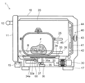
前述の通り食品は、通常の場合、上段トレイ受け25または下段トレイ受け26が支えるトレイまたはラックに支持された状態で調理される。しかしながら、食品を鍋のような調理用の容器に入れた状態で調理を行いたいときもある。そのような場合は、前記トレイまたはラックを取り外し、その後へ、図2、3に示すように容器Cを挿入する。通常、容器Cの底面は平坦であり、底トレイ33に密着する。また通常、容器Cは底トレイ33の中央付近に置かれるので、赤外線温度センサ60の真上に容器Cが来ることになる。
As described above, the food is normally cooked while being supported by the tray or rack supported by the
図2、3に示す容器Cは蓋付きの鍋であり、内部には食品Fが出し汁Bと共に入れられている。このように蓋付きの容器Cに入れた状態の食品Fを調理する場合、熱風加熱モードか蒸気加熱モードが選択されることが多いが、容器Cの本体または蓋が誘電体製である場合、あるいは蓋が取り外されている場合には、高周波加熱モードを選択することもできる。 A container C shown in FIGS. 2 and 3 is a pan with a lid, and the food F is put together with the soup B inside. When cooking the food F in a state of being put in the container C with a lid in this way, the hot air heating mode or the steam heating mode is often selected, but when the main body or the lid of the container C is made of a dielectric, Alternatively, when the lid is removed, the high-frequency heating mode can be selected.
どのような調理モードであれ、加熱を行うと、容器Cの内容物の温度が上昇し、容器C自体も温度上昇する。底トレイ33の中で、容器Cが接している箇所の温度も上昇する。
In any cooking mode, when heating is performed, the temperature of the contents of the container C rises, and the temperature of the container C itself also rises. In the
底トレイ33の中で、容器Cが接している箇所の温度は、アンテナ室32の空間を通して赤外線温度センサ60により測定される。測定値に補正係数を乗じれば、食品Fの温度を知ることができる。補正係数は実験を通じて求めておくと良い。制御装置70は、食品Fの温度が操作部16で設定した所定温度になるように加熱を制御する。
In the
高周波加熱モードでは、赤外線温度センサ60は、回転アンテナ34の開口部34aが視野を通過している間に温度測定を行う。開口部34aは図4の線Aから線Bまでの角度区間で赤外線温度センサ60の視野に重なる。
In the high-frequency heating mode, the
前述の通り、回転アンテナ34は回転状態から回転停止状態に至るときは、開口部34aが赤外線温度センサ60の視野に重なる位置で停止状態となる。従って、高周波加熱モード以外の調理モードでも、赤外線温度センサ60による温度測定に何ら支障はない。
As described above, when the
食品Fから発生する蒸気も、蒸気調理で用いる蒸気も、容器Cの底面と底トレイ33の間には入り込まない。そのため、蒸気による撹乱を受けることなく容器Cの温度を測定することができる。また赤外線温度センサ60と底トレイ33までの距離が一定なので測定誤差が小さくて済む。
Neither steam generated from the food F nor steam used for steam cooking enter between the bottom surface of the container C and the
赤外線温度センサ60は底トレイ33で加熱室20から遮断されているので、蒸気も、食品から垂れる水分も、油煙も、赤外線温度センサ60に付着しない。このため、赤外線温度センサ60の温度測定が安定する。底トレイ33は熱風からも赤外線温度センサ60を守るので、赤外線温度センサ60に耐熱性は求められない。
Since the
加熱室20内の気体が貫通孔32aを通じて漏洩することも、外部の空気が貫通孔32aを通じて加熱室20に侵入することもない。このため、加熱室20に内部に蒸気を満たして行う低酸素調理が可能である。
Gas in the
貫通孔32aは、アンテナ室32からの高周波の漏洩を防ぐことができる大きさとされており、その外側に赤外線温度センサ60が配置されるので、赤外線温度センサ60は高周波によりダメージを与えられることがない。しかしながら、赤外線温度センサ60が高周波によってはダメージを受けない構造のものであるならば、アンテナ室32の外側に置かずとも、アンテナ室32の底部に窪みを形成し、その中に赤外線温度センサ60を収納するといった構成も可能である。
The through
容器Cが加圧または減圧を行う容器である場合、その内部温度を測定することは、通常の高周波調理装置では困難であるが、本発明の高周波調理装置1では、加圧や減圧のため容器Cの密閉度が高くなっていたとしても、それを問題にすることなく内部温度を測定することができる。 When the container C is a container that pressurizes or depressurizes, it is difficult to measure the internal temperature with a normal high-frequency cooking apparatus. Even if the sealing degree of C is high, the internal temperature can be measured without making it a problem.
容器Cの底部がアルミニウムのような熱伝導率の高い材料で形成されていたとすれば、それだけ精度の高い温度測定を行うことができる。 If the bottom of the container C is formed of a material having high thermal conductivity such as aluminum, temperature measurement with high accuracy can be performed.
食品を調理用の皿に載せ、その皿を底トレイ33に載置することもできる。この場合も、皿がアルミニウムのような熱伝導率の高い材料で形成されていたとすれば、それだけ精度の高い温度測定を行うことができる。
It is also possible to place food on a cooking dish and place the dish on the
調理用の容器や皿を使用することなく、食品を直接底トレイ33に載置して調理を行うこともできる。
The food can be directly placed on the
以下のように改変を加えたものを高周波調理装置1の実施形態とすることもできる。
What added the modification as follows can also be made into embodiment of the high
底トレイ33には、赤外線温度センサ60による温度検知位置に、目印をつけることができる。使用者は目印が隠れるように容器、皿、あるいは食品そのものを置けば良く、便利である。目印は、印刷、底トレイ33の射出成形金型に施す陰刻や陽刻、シールの貼り付けなど、様々な手法で形成することができる。
The
底トレイ33には、少なくとも赤外線温度センサ60による温度検知位置に撥水処理を施すことができる。これにより、赤外線温度センサ60による温度検知位置に水分や汚れ
が付着しにくくなり、それらによって赤外線温度センサ60の測定精度が低下するのを避けることができる。撥水処理は、例えばフッ素樹脂(ポリテトラフロオロエチレン)のコーティングで実施できる。
The
底トレイ33には、少なくとも赤外線温度センサ60による温度検知位置に、傾斜を形成することができる。これにより、赤外線温度センサ60による温度検知位置に液体が溜まりにくくなるので、赤外線温度センサ60の測定精度を維持できる。
The
底トレイ33は、赤外線温度センサ60による温度検知位置を、周囲よりも高く形成することができる。これにより、赤外線温度センサ60による温度検知位置が、底トレイ33に載置される物体(容器、皿、食品)に密着することになり、蒸気の侵入を確実に阻止することができる。
The
以上、本発明の実施形態につき説明したが、本発明の範囲はこれに限定されるものではなく、発明の主旨を逸脱しない範囲で種々の変更を加えて実施することができる。 Although the embodiments of the present invention have been described above, the scope of the present invention is not limited to these embodiments, and various modifications can be made without departing from the spirit of the invention.
本発明は高周波調理装置に広く利用可能である。 The present invention can be widely used for high-frequency cooking apparatuses.
1 高周波調理装置
10 筐体
11 扉
20 加熱室
30 マグネトロン
31 導波管
32 アンテナ室
32a 貫通孔
33 底トレイ
34 回転アンテナ
34a 開口部
40 コンベクションヒータユニット
50 蒸気発生装置
60 赤外線温度センサ
70 制御装置
DESCRIPTION OF
Claims (9)
前記加熱室の底部に誘電体製の底トレイがはめ込まれ、前記底トレイの下は高周波が導入されるアンテナ室として構成されるとともに、前記アンテナ室の空間を通して前記底トレイに載置された物体の温度を測定する赤外線温度センサが配置されることを特徴とする高周波調理装置。 In a high-frequency cooking apparatus equipped with a cooking mode for introducing steam into the heating chamber,
A dielectric bottom tray is fitted in the bottom of the heating chamber, and the bottom tray is configured as an antenna chamber into which high frequency is introduced, and an object placed on the bottom tray through the space of the antenna chamber An infrared temperature sensor for measuring the temperature of the food is disposed.
Priority Applications (1)
| Application Number | Priority Date | Filing Date | Title |
|---|---|---|---|
| JP2010108965A JP5626851B2 (en) | 2010-05-11 | 2010-05-11 | High frequency cooking equipment |
Applications Claiming Priority (1)
| Application Number | Priority Date | Filing Date | Title |
|---|---|---|---|
| JP2010108965A JP5626851B2 (en) | 2010-05-11 | 2010-05-11 | High frequency cooking equipment |
Publications (2)
| Publication Number | Publication Date |
|---|---|
| JP2011237123A true JP2011237123A (en) | 2011-11-24 |
| JP5626851B2 JP5626851B2 (en) | 2014-11-19 |
Family
ID=45325300
Family Applications (1)
| Application Number | Title | Priority Date | Filing Date |
|---|---|---|---|
| JP2010108965A Expired - Fee Related JP5626851B2 (en) | 2010-05-11 | 2010-05-11 | High frequency cooking equipment |
Country Status (1)
| Country | Link |
|---|---|
| JP (1) | JP5626851B2 (en) |
Cited By (4)
| Publication number | Priority date | Publication date | Assignee | Title |
|---|---|---|---|---|
| WO2015020008A1 (en) * | 2013-08-06 | 2015-02-12 | シャープ株式会社 | Heating cooker |
| JP2023003444A (en) * | 2021-06-24 | 2023-01-17 | 三菱電機株式会社 | heating cooker |
| WO2024101283A1 (en) * | 2022-11-09 | 2024-05-16 | シャープ株式会社 | Device |
| WO2025046830A1 (en) * | 2023-08-31 | 2025-03-06 | シャープ株式会社 | Treatment device |
Citations (13)
| Publication number | Priority date | Publication date | Assignee | Title |
|---|---|---|---|---|
| JPS57186410U (en) * | 1982-04-28 | 1982-11-26 | ||
| JPS57196905U (en) * | 1981-06-08 | 1982-12-14 | ||
| JPS58108310U (en) * | 1982-01-19 | 1983-07-23 | 三洋電機株式会社 | microwave oven |
| JPS5932721A (en) * | 1982-08-19 | 1984-02-22 | Matsushita Electric Ind Co Ltd | High frequency heating device |
| JPS6136207U (en) * | 1984-08-01 | 1986-03-06 | 三菱電機株式会社 | High frequency heating device |
| JPS6159120A (en) * | 1984-08-30 | 1986-03-26 | Matsushita Electric Ind Co Ltd | Cooker with infrared sensor |
| JPH0791670A (en) * | 1993-09-20 | 1995-04-04 | Matsushita Electric Ind Co Ltd | High frequency heating device |
| JP2001108243A (en) * | 1999-10-01 | 2001-04-20 | Sanyo Electric Co Ltd | Microwave oven |
| JP2003137604A (en) * | 2001-11-05 | 2003-05-14 | Matsushita Electric Ind Co Ltd | Water repellent coating |
| JP2003249342A (en) * | 2002-02-25 | 2003-09-05 | Matsushita Electric Ind Co Ltd | Induction heating cooker |
| JP2004176962A (en) * | 2002-11-26 | 2004-06-24 | Sanyo Electric Co Ltd | Cooker |
| JP2005172263A (en) * | 2003-12-08 | 2005-06-30 | Nisshin Steel Co Ltd | Microwave oven |
| JP2007139245A (en) * | 2005-11-16 | 2007-06-07 | Matsushita Electric Ind Co Ltd | High frequency cooking device |
-
2010
- 2010-05-11 JP JP2010108965A patent/JP5626851B2/en not_active Expired - Fee Related
Patent Citations (13)
| Publication number | Priority date | Publication date | Assignee | Title |
|---|---|---|---|---|
| JPS57196905U (en) * | 1981-06-08 | 1982-12-14 | ||
| JPS58108310U (en) * | 1982-01-19 | 1983-07-23 | 三洋電機株式会社 | microwave oven |
| JPS57186410U (en) * | 1982-04-28 | 1982-11-26 | ||
| JPS5932721A (en) * | 1982-08-19 | 1984-02-22 | Matsushita Electric Ind Co Ltd | High frequency heating device |
| JPS6136207U (en) * | 1984-08-01 | 1986-03-06 | 三菱電機株式会社 | High frequency heating device |
| JPS6159120A (en) * | 1984-08-30 | 1986-03-26 | Matsushita Electric Ind Co Ltd | Cooker with infrared sensor |
| JPH0791670A (en) * | 1993-09-20 | 1995-04-04 | Matsushita Electric Ind Co Ltd | High frequency heating device |
| JP2001108243A (en) * | 1999-10-01 | 2001-04-20 | Sanyo Electric Co Ltd | Microwave oven |
| JP2003137604A (en) * | 2001-11-05 | 2003-05-14 | Matsushita Electric Ind Co Ltd | Water repellent coating |
| JP2003249342A (en) * | 2002-02-25 | 2003-09-05 | Matsushita Electric Ind Co Ltd | Induction heating cooker |
| JP2004176962A (en) * | 2002-11-26 | 2004-06-24 | Sanyo Electric Co Ltd | Cooker |
| JP2005172263A (en) * | 2003-12-08 | 2005-06-30 | Nisshin Steel Co Ltd | Microwave oven |
| JP2007139245A (en) * | 2005-11-16 | 2007-06-07 | Matsushita Electric Ind Co Ltd | High frequency cooking device |
Cited By (7)
| Publication number | Priority date | Publication date | Assignee | Title |
|---|---|---|---|---|
| WO2015020008A1 (en) * | 2013-08-06 | 2015-02-12 | シャープ株式会社 | Heating cooker |
| JP2015031489A (en) * | 2013-08-06 | 2015-02-16 | シャープ株式会社 | Cooker |
| CN105556212A (en) * | 2013-08-06 | 2016-05-04 | 夏普株式会社 | Heating cooker |
| CN105556212B (en) * | 2013-08-06 | 2017-05-24 | 夏普株式会社 | Heating cooker |
| JP2023003444A (en) * | 2021-06-24 | 2023-01-17 | 三菱電機株式会社 | heating cooker |
| WO2024101283A1 (en) * | 2022-11-09 | 2024-05-16 | シャープ株式会社 | Device |
| WO2025046830A1 (en) * | 2023-08-31 | 2025-03-06 | シャープ株式会社 | Treatment device |
Also Published As
| Publication number | Publication date |
|---|---|
| JP5626851B2 (en) | 2014-11-19 |
Similar Documents
| Publication | Publication Date | Title |
|---|---|---|
| CN100554789C (en) | Cooking device and cooking method | |
| US20110132346A1 (en) | Cooking device | |
| JP3800190B2 (en) | High-frequency heating device with steam generation function | |
| WO2005106333A1 (en) | Microwave heating method and device therefor | |
| JP7432826B2 (en) | heating cooker | |
| JP5626851B2 (en) | High frequency cooking equipment | |
| JP6846623B2 (en) | Cooker | |
| JP6761977B2 (en) | Cooker | |
| JP2010054097A (en) | Heating cooker | |
| CN103221748B (en) | Heating device | |
| JP6461656B2 (en) | Cooker | |
| JP2005016788A (en) | Cooker | |
| JP2019066177A (en) | Heating cooker | |
| JP2021167702A (en) | Cooker and cooker system | |
| JP2011247484A (en) | Heating cooker | |
| JP4251156B2 (en) | Cooker | |
| JP2011007493A (en) | Heating cooker and steam generating device for heating cooker | |
| JP2006317019A (en) | High frequency cooking device | |
| US20260082458A1 (en) | Steamer insert and method of operating a microwave oven | |
| JP2020041798A (en) | Heating cooker | |
| US20260076503A1 (en) | Steamer insert and method of operating a microwave oven | |
| JP2021089083A (en) | Heating cooker | |
| JP2007078302A (en) | High frequency cooking device | |
| JP5766056B2 (en) | Cooker | |
| JPH06281156A (en) | Food heating cooker |
Legal Events
| Date | Code | Title | Description |
|---|---|---|---|
| A621 | Written request for application examination |
Free format text: JAPANESE INTERMEDIATE CODE: A621 Effective date: 20130401 |
|
| A977 | Report on retrieval |
Free format text: JAPANESE INTERMEDIATE CODE: A971007 Effective date: 20140129 |
|
| A131 | Notification of reasons for refusal |
Free format text: JAPANESE INTERMEDIATE CODE: A131 Effective date: 20140212 |
|
| A521 | Written amendment |
Free format text: JAPANESE INTERMEDIATE CODE: A523 Effective date: 20140414 |
|
| TRDD | Decision of grant or rejection written | ||
| A01 | Written decision to grant a patent or to grant a registration (utility model) |
Free format text: JAPANESE INTERMEDIATE CODE: A01 Effective date: 20140902 |
|
| A61 | First payment of annual fees (during grant procedure) |
Free format text: JAPANESE INTERMEDIATE CODE: A61 Effective date: 20140925 |
|
| R150 | Certificate of patent or registration of utility model |
Ref document number: 5626851 Country of ref document: JP Free format text: JAPANESE INTERMEDIATE CODE: R150 |
|
| S531 | Written request for registration of change of domicile |
Free format text: JAPANESE INTERMEDIATE CODE: R313531 |
|
| R350 | Written notification of registration of transfer |
Free format text: JAPANESE INTERMEDIATE CODE: R350 |
|
| LAPS | Cancellation because of no payment of annual fees |