JP2011237146A - Air conditioner - Google Patents
Air conditioner Download PDFInfo
- Publication number
- JP2011237146A JP2011237146A JP2010110746A JP2010110746A JP2011237146A JP 2011237146 A JP2011237146 A JP 2011237146A JP 2010110746 A JP2010110746 A JP 2010110746A JP 2010110746 A JP2010110746 A JP 2010110746A JP 2011237146 A JP2011237146 A JP 2011237146A
- Authority
- JP
- Japan
- Prior art keywords
- refrigerant
- air conditioner
- indoor unit
- air
- gas
- Prior art date
- Legal status (The legal status is an assumption and is not a legal conclusion. Google has not performed a legal analysis and makes no representation as to the accuracy of the status listed.)
- Pending
Links
Images
Landscapes
- Air-Conditioning For Vehicles (AREA)
Abstract
Description
本発明は、冷媒を用いて冷凍、ヒートポンプサイクルを構成して冷媒暖房をおこなう空気調和機に関するもので、特に室内機と室外機を接続配管で繋いでサイクルを構成する装置において、冷媒の大気放出を抑え、酸素や水分のサイクル中への混入を低減して信頼性を向上させる技術を提供するものである。 The present invention relates to an air conditioner that performs refrigerant heating by forming a refrigeration and heat pump cycle using a refrigerant, and particularly in an apparatus that constitutes a cycle by connecting an indoor unit and an outdoor unit with a connection pipe, the refrigerant is released into the atmosphere. It is possible to provide a technology for improving reliability by suppressing oxygen and moisture during the cycle.
分離型の空気調和機は、通常室外機に冷媒が予め封入されており、室内機と室外機を接続配管で繋いだ後、冷媒を接続配管および室内機に開放して設置を行うものである。 In the separation type air conditioner, the refrigerant is normally sealed in the outdoor unit in advance, and the indoor unit and the outdoor unit are connected by a connection pipe, and then the refrigerant is opened to the connection pipe and the indoor unit for installation. .
従来は、設置の際にサイクル中の空気を排出する方法として、真空ポンプによる方法や、室外機の液側の接続バルブ(二方弁)を開けて封入されている冷媒の一部を冷媒を接続配管および室内機に開放して、すぐにまた二方弁を閉じ、ガス側のチャージバルブ付きの接続バルブ(三方弁)のチャージバルブを開けて、冷媒と一緒に内部の空気を放出するという操作を2、3回行って最後に二方弁三方弁を全開する方法があった。このとき、配管接続部の漏れチェックは冷媒を一部開放した際にその圧力を利用して行っていた。 Conventionally, as a method of exhausting the air in the cycle at the time of installation, a method using a vacuum pump or a liquid-side connection valve (two-way valve) of the outdoor unit is opened to remove a part of the enclosed refrigerant. Open the connection pipe and indoor unit, immediately close the two-way valve again, open the charge valve of the connection valve (three-way valve) with a charge valve on the gas side, and release the internal air together with the refrigerant There was a method of performing the operation a few times and finally fully opening the two-way valve and the three-way valve. At this time, the leak check of the pipe connection part was performed using the pressure when a part of the refrigerant was released.
やがて、オゾン層保護の観点から冷媒の大気放出が問題視されるようになると、真空引きによる内部の空気排出方法が一般的となった。また、室内機側の空気を炭酸ガスで置換し、正圧がかかった状態の炭酸ガスを吸着して回収した後、冷媒を開放する方法もある(例えば、特許文献1参照)。 Eventually, when the release of refrigerant into the atmosphere became a problem from the viewpoint of protecting the ozone layer, the internal air discharge method by vacuuming became common. Further, there is a method in which the air on the indoor unit side is replaced with carbon dioxide, and the refrigerant is released after adsorbing and collecting the carbon dioxide in a positive pressure state (for example, see Patent Document 1).
一方冷媒については、代替フロンに対する考え方が、オゾン層の保護に加えて地球の温暖化防止へと進展してきており、自然冷媒や、炭素と炭素間に2重結合を有するハイドロフルオロオレフィンなどの冷媒が注目されている。ハイドロフルオロオレフィンは、R134aの代替冷媒として特に注目されており、自動車用エアコンディショナーへの実用化の検討が推進されている。その温暖化係数(100年)は4で、R134aの1,300、エアコンなどで使用されているR410Aの1730に比べてきわめて小さい。この温暖化係数が小さいという特性は、炭素間に2重結合を有し分解し易いことに起因している。 On the other hand, with regard to refrigerants, the idea of alternative chlorofluorocarbons has progressed to prevent global warming in addition to protecting the ozone layer. Natural refrigerants and refrigerants such as hydrofluoroolefins having a double bond between carbon and carbon Is attracting attention. Hydrofluoroolefins are particularly attracting attention as alternative refrigerants for R134a, and studies on practical application to automotive air conditioners are being promoted. Its warming potential (100 years) is 4, which is very small compared to 1,300 for R134a and 1730 for R410A used in air conditioners and the like. This characteristic that the warming coefficient is small is attributed to the fact that there is a double bond between carbon and it is easy to decompose.
上記従来の空気調和機の設置に関して、室内機および接続配管内の空気を冷媒置換する方法は環境保護の観点から容認できないことは言うまでもない。 Needless to say, with respect to installation of the conventional air conditioner, the method of replacing the air in the indoor unit and the connecting pipe with the refrigerant is not acceptable from the viewpoint of environmental protection.
真空引きによる内部の空気排出方法においては、真空引きを終え、冷媒を一部あるいは全部開放してから漏れチェックを行うことになる。もし、接続が正常でなかったり、真空引きが不十分であったりすると、空気がサイクル中に混入する可能性がある。空気がサイクル中に混入すると、酸素や水分が装置の信頼性に悪影響をもたらす。冷媒がR410Aの場合、冷凍機油にエステル系のオイルがよく用いられる。このときオイルが加水分解され、金属石鹸を生じたりして詰まりや圧縮機の故障につながる可能性がある。 In the internal air discharging method by evacuation, the leakage check is performed after evacuation is completed and a part or all of the refrigerant is released. If the connection is not normal or the evacuation is inadequate, air can enter the cycle. If air enters during the cycle, oxygen and moisture can adversely affect the reliability of the device. When the refrigerant is R410A, ester oil is often used as the refrigerator oil. At this time, the oil may be hydrolyzed to produce metal soap, which may lead to clogging or compressor failure.
冷媒がハイドロフルオロオレフィンの場合には、酸素や水分により冷媒が分解し反応性生物が金属材料や有機材料に対し悪影響をもたらし故障につながる可能性がある。また、炭酸ガスで置換し、正圧がかかった状態の炭酸ガスを吸着して回収した後冷媒を開放する方法では、炭酸ガス置換および加圧用の炭酸ガスボンベと、吸着用のボンベとを用意する必要がある。 When the refrigerant is a hydrofluoroolefin, the refrigerant is decomposed by oxygen or moisture, and the reactive organism may adversely affect the metal material or organic material, leading to failure. Also, in the method of substituting with carbon dioxide and adsorbing and collecting carbon dioxide in a positive pressure state and then releasing the refrigerant, a carbon dioxide gas cylinder for carbon dioxide substitution and pressurization and an adsorption cylinder are prepared. There is a need.
本発明は、こうした課題を解決し、準備の手間をかけず、室内機、室外機の接続を確実に行うことのできる信頼性の高い装置を提供するものである。 The present invention solves these problems, and provides a highly reliable device that can reliably connect an indoor unit and an outdoor unit without requiring preparation.
上記従来の課題を解決するために、本発明の空気調和機は、作動冷媒とは反応性が低く、常温常圧においては気体となる物質を、製造段階で室外機あるいは室内機に前記作動冷媒とは分離して封入することを特徴とするものである。これにより、梱包段階で前記室内機に空気が侵入するのを防いだり、前記室内機と前記室外機とを接続した際の内部の空気を前記封入物質により置換排出したりすることができる。 In order to solve the above-described conventional problems, the air conditioner of the present invention has a low reactivity with a working refrigerant, and a substance that becomes a gas at normal temperature and pressure is applied to the working refrigerant in an outdoor unit or an indoor unit at the manufacturing stage. Is characterized by being sealed and sealed. Accordingly, it is possible to prevent air from entering the indoor unit at the packing stage, or to replace and discharge the internal air when the indoor unit and the outdoor unit are connected to each other with the enclosed substance.
また、本発明の空気調和機は、前記封入物質が充填された容器を、前記室外機あるいは前記室内機の前記作動冷媒の液比率が高い部分に配置し、前記室内機と前記室外機とを接続した際の内部の空気を前記封入物質により置換排出するものである。これにより、前記封入物質により配管内部を正圧とし、配管径の細い側から太い側へ向けて排出することで特に有害な酸素や水分を短時間で排出することができる。また、前記置換排出過程において、前記封入物質により配管内部が正圧とし、この段階で漏れチェックを行うことができる。これにより、接続状態の不具合を、前記作動冷媒を開放する前に確認することができる。 In the air conditioner of the present invention, the container filled with the enclosed substance is disposed in a portion where the liquid ratio of the working refrigerant of the outdoor unit or the indoor unit is high, and the indoor unit and the outdoor unit are arranged. The internal air at the time of connection is replaced and discharged by the enclosed substance. Thereby, especially harmful oxygen and moisture can be discharged in a short time by setting the inside of the pipe to a positive pressure with the encapsulated substance and discharging the pipe from the narrow side to the thick side. Further, in the replacement discharge process, the inside of the pipe is set to a positive pressure by the enclosed substance, and a leak check can be performed at this stage. Thereby, the malfunction of a connection state can be confirmed before opening the said working refrigerant.
また、本発明の空気調和機は、前記容器の内部に、酸素および水を吸着する吸着剤を内包するものである。これにより、設置が完了し装置を使用しだしてからも、冷媒中の酸素および水を除去することができる。 The air conditioner of the present invention includes an adsorbent that adsorbs oxygen and water inside the container. Thereby, even after installation is completed and the apparatus is used, oxygen and water in the refrigerant can be removed.
本発明の空気調和機は、前記室内機に空気が侵入するのを防いだり、配管内部の有害な酸素や水分を短時間で排出したりすることができる。また、本発明の空気調和機は、冷媒解放前に接続のチェックが可能であり、信頼性の高い設置ができる。また、本発明の空気調和機は、前記封入物質の容器内に有害な酸素や水分の吸着剤を備えることで、設置以後も信頼性の高い装置を実現できる。 The air conditioner of the present invention can prevent air from entering the indoor unit and can discharge harmful oxygen and moisture inside the pipe in a short time. Further, the air conditioner of the present invention can be checked for connection before releasing the refrigerant, and can be installed with high reliability. In addition, the air conditioner of the present invention can provide a highly reliable device even after installation by providing a harmful oxygen or moisture adsorbent in the container of the enclosed substance.
第1の発明は、作動冷媒とは反応性が低く、常温常圧においては気体となる物質を、製造段階で室外機あるいは室内機に前記作動冷媒とは分離して封入することを特徴とするものである。これにより、梱包段階で前記室内機全体に前記封入物質を封入すれば、前記室内機空気が侵入するのを防ぐことができる。前記室内機あるいは前記室外機に前記封入物質が充填された容器を備えれば、接続した際の内部の空気を前記封入物質により置換排出することができる。従って、空気の侵入を防いで信頼性の高い設置を行うことができる。 According to a first aspect of the present invention, a substance that is low in reactivity with a working refrigerant and becomes a gas at normal temperature and normal pressure is enclosed in an outdoor unit or an indoor unit separately from the working refrigerant in a manufacturing stage. Is. Thereby, if the said enclosure substance is enclosed with the said whole indoor unit in a packing stage, it can prevent that the said indoor unit air penetrate | invades. If the indoor unit or the outdoor unit is provided with a container filled with the encapsulating substance, the internal air when connected can be replaced and discharged by the encapsulating substance. Therefore, air can be prevented from entering and highly reliable installation can be performed.
第2の発明は、第1の発明において、前記封入物質が充填された容器を、前記室外機あるいは前記室内機の前記作動冷媒の液比率が高い部分に配置し、前記室内機と前記室外機とを接続した際の内部の空気を前記封入物質により置換排出するものである。これにより
、前記封入物質により配管内部を正圧とし、配管径の細い側から太い側へ向けて排出することで特に有害な酸素や水分をより短時間で排出することができる。また、前記置換排出過程において、前記封入物質により配管内部が正圧とし、この段階で漏れチェックを行うことができる。従って、作業を速やかに、確実に行うことができる。
According to a second invention, in the first invention, the container filled with the encapsulating substance is disposed in a portion of the outdoor unit or the indoor unit where the liquid ratio of the working refrigerant is high, and the indoor unit and the outdoor unit The internal air at the time of connection is replaced and discharged by the enclosed substance. Accordingly, particularly harmful oxygen and moisture can be discharged in a shorter time by setting the inside of the pipe to a positive pressure with the enclosed substance and discharging the pipe from the thin pipe diameter toward the thick pipe. Further, in the replacement discharge process, the inside of the pipe is set to a positive pressure by the enclosed substance, and a leak check can be performed at this stage. Therefore, the work can be performed promptly and reliably.
第3の発明は、第2の発明において前記容器の内部に、酸素および水を吸着する吸着剤を内包するものである。これにより、設置が完了し装置を使用しだしてからも、冷媒中の酸素および水を除去することができる。従って、設置以後も信頼性の高い装置を実現できる。 According to a third invention, in the second invention, an adsorbent that adsorbs oxygen and water is included in the container. Thereby, even after installation is completed and the apparatus is used, oxygen and water in the refrigerant can be removed. Therefore, a highly reliable device can be realized after installation.
第4の発明は、第3の発明において、前記容器の内部を前記作動冷媒が流れるよう構成したものである。これにより、前記作動冷媒中の酸素および水は、前記容器内部の前記吸着剤に吸着され易くなる。従って、設置以後も装置の信頼性が向上する。 According to a fourth invention, in the third invention, the working refrigerant flows in the container. Thereby, oxygen and water in the working refrigerant are easily adsorbed by the adsorbent inside the container. Therefore, the reliability of the apparatus is improved after installation.
第5の発明は、第1から第4に発明において、前記作動冷媒の成分として炭素と炭素間に2重結合を有するハイドロフルオロオレフィンを有するものである。これにより、信頼性を確保しつつ、前記作動冷媒の温暖化係数を低減することができる。従って、環境負荷の少ない空気調和機を提供することができる。 According to a fifth invention, in the first to fourth inventions, a hydrofluoroolefin having a double bond between carbon and carbon as a component of the working refrigerant is provided. Thereby, the warming potential of the working refrigerant can be reduced while ensuring reliability. Therefore, it is possible to provide an air conditioner with a low environmental load.
以下、本発明の実施の形態について、図面を参照しながら説明する。 Hereinafter, embodiments of the present invention will be described with reference to the drawings.
(実施の形態1)
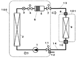
図1は、本発明の第1の実施の形態における空気調和機の構成図を示すものである。図1に示すように、第1の実施の形態における空気調和機は、室外機100と室内機101を、接続配管つまり接続液配管13および接続ガス配管14で接続して装置を構成している。
(Embodiment 1)
FIG. 1 shows a configuration diagram of an air conditioner according to a first embodiment of the present invention. As shown in FIG. 1, the air conditioner according to the first embodiment configures an apparatus by connecting an
室外機100には、三方弁11、圧縮手段である圧縮機1、室外熱交換手段である室外熱交換器2、冷媒を減圧膨張させる膨張弁3、遮断弁4、ガス容器5、二方弁7が備えられており、今述べた順に冷媒が流れる。室内機101には、液側継ぎ手8、室内熱交換手段である室内熱交換器9、ガス側継ぎ手10が備えられている。そして、二方弁7と液側継ぎ手8を接続液配管13が、ガス側継ぎ手10と三方弁11とを接続ガス配管14が接続している。
The
そして、三方弁11には、冷媒をチャージしたり、真空引きを行ったりするためにチャージバルブ12がついている。さらに、ガス容器5の内部には、酸素を吸着する鉄系の吸着剤や水を吸着するゼオライトなどの吸着剤6が備えられている。ここで、室外機100、室内機101には通常熱交換器に空気を通すための送風機が備えられているが便宜上省略する。作動冷媒としては様々な種類のものがあるが、図1のような空気調和機ではR410Aなどが一般的である。
The three-
図1において冷媒は圧縮機1で高圧に圧縮され、室外熱交換器2で放熱して凝縮した後、膨張弁3で減圧膨張しつつ室内熱交換器9で吸熱して蒸発し圧縮機1へ戻る。つまり、図1の空気調和機は冷房専用の装置となっている。
In FIG. 1, the refrigerant is compressed to a high pressure by the compressor 1, dissipates heat by the
製造段階においては、室外機の三方弁11から圧縮機1、遮断弁4までの空間に冷媒が封入されており、遮断弁4からガス容器5、二方弁7までの空間には、作動冷媒とは反応性が低く、常温常圧においては気体となる封入物質が製造段階で封入されている。また、室内機101にも、封入物質が封入され、液側継ぎ手8およびガス側継ぎ手10には蓋がされている。具体的な封入物質としては、炭酸ガスや窒素ガスなどが安価であり環境負荷
の点からも望ましい。図1の空気調和機では、ガス容器5には小容量でも封入量を多く取れる炭酸ガスを、室内機101には窒素ガスを使用する。
In the manufacturing stage, the refrigerant is sealed in the space from the three-
そして、設置時には、室外機100と室内機101を、接続液配管13および接続ガス配管14で接続するが、室内機101には窒素ガスが封入されており、蓋を開けてもすぐに空気に置換されるわけではないので、酸素や水分の浸入を低減することができる。
At the time of installation, the
接続が終わったら、二方弁7を開き、ガス容器5の中の炭酸ガスを室内機側に導入する。このとき、最初のうちだけチャージバルブ12を開けておくと空気を効率よく排出することができる。そして、炭酸ガスの導入が終わると、接続液配管13および接続ガス配管14と室内機101は加圧状態となり、接続部の漏れチェックを行うと冷媒を導入する前に漏れチェックができる。これにより、不完全な接続が原因で冷媒を漏らしてしまったり、真空引き時に空気が配管内に侵入させてしまったりするのを防ぐことができる。
When the connection is completed, the two-
漏れチェックが終わったら、チャージバルブ12から炭酸ガスを放出し、真空引きを行う。すでに、酸素や水分は放出されているので、比較的短時間で真空引きを終了しても問題はない。真空引きが終了したら、チャージバルブ12を閉じ遮断弁4と三方弁11を開けて設置作業は終了する。
When the leak check is completed, carbon dioxide gas is discharged from the
ガス容器5の内部には、吸着剤6が備えられており、酸素や水分が残留していたり、使用する間に内部の材料から生成されたりしたとしても取り除くことができる。また、冷媒はガス容器5を通るよう構成されているので、酸素や水が冷媒中に存在すればすぐに取り除かれる。ガス容器5は液側に配置されているので、比較的高温になることもなく吸着された酸素や水が離脱するのも防ぐことができる。
An
また、最近は環境負荷低減の観点から、温暖化係数の小さな冷媒に関心が集まっている。その代表的なものとして、炭素と炭素間に2重結合を有するハイドロフルオロオレフィンが挙げられるが、反面とても分解し易く酸素や水の混入は冷媒の分解を加速し、フッ化水素などの好ましくない反生成物が生じる可能性もある。図1の空気調和機では上に述べたように酸素や水の混入に対し、設置時も設置後の運転時にも高信頼性を実現できるので、ハイドロフルオロオレフィンのような冷媒も問題なく使用することができる。従って、環境負荷の少ない空気調和機を実現することができる。 Recently, from the viewpoint of reducing the environmental load, attention has been focused on refrigerants having a small global warming potential. A typical example is a hydrofluoroolefin having a double bond between carbons, but on the other hand, it is very easy to decompose, and oxygen and water contamination accelerates the decomposition of the refrigerant, which is undesirable such as hydrogen fluoride. An anti-product may also occur. In the air conditioner of FIG. 1, as described above, it is possible to achieve high reliability against the mixing of oxygen and water, both during installation and during operation after installation, so that a refrigerant such as hydrofluoroolefin can be used without any problem. be able to. Therefore, an air conditioner with less environmental load can be realized.
以上のように、本発明にかかる空気調和機は、作動冷媒とは反応性が低く、常温常圧においては気体となる物質を、製造段階で室外機あるいは室内機に前記作動冷媒とは分離して封入するもので、酸素や水の混入に対し、設置時も設置後の運転時にも高信頼性を実現できる。その結果、炭素と炭素間に2重結合を有するハイドロフルオロオレフィンのような、分解しやすい冷媒も使用することができ、環境性に優れている。 As described above, the air conditioner according to the present invention has a low reactivity with a working refrigerant and separates a substance that becomes a gas at room temperature and normal pressure from the working refrigerant into an outdoor unit or an indoor unit at the manufacturing stage. High reliability can be achieved for both oxygen and water contamination during and after installation. As a result, a refrigerant that is easily decomposed, such as a hydrofluoroolefin having a double bond between carbon and carbon, can be used, and the environment is excellent.
そして、空気調和機だけに止まらず、セパレート型のショーケースや冷凍機、ヒートポンプ式の温水器などに広く適用することができ、効果をもたらすものである。 Further, the present invention is not limited to the air conditioner, and can be widely applied to a separate type showcase, a refrigerator, a heat pump type water heater, and the like, and brings about an effect.
100 室外機
101 室内機
1 圧縮機
2 室外熱交換器
3 膨張弁
4 遮断弁
5 ガス容器
6 吸着剤
7 二方弁
8 液側継ぎ手
9 室内熱交換器
10 ガス側継ぎ手
11 三方弁
12 チャージバルブ
13 接続液配管
14 接続ガス配管
DESCRIPTION OF
Claims (5)
Priority Applications (1)
| Application Number | Priority Date | Filing Date | Title |
|---|---|---|---|
| JP2010110746A JP2011237146A (en) | 2010-05-13 | 2010-05-13 | Air conditioner |
Applications Claiming Priority (1)
| Application Number | Priority Date | Filing Date | Title |
|---|---|---|---|
| JP2010110746A JP2011237146A (en) | 2010-05-13 | 2010-05-13 | Air conditioner |
Publications (1)
| Publication Number | Publication Date |
|---|---|
| JP2011237146A true JP2011237146A (en) | 2011-11-24 |
Family
ID=45325322
Family Applications (1)
| Application Number | Title | Priority Date | Filing Date |
|---|---|---|---|
| JP2010110746A Pending JP2011237146A (en) | 2010-05-13 | 2010-05-13 | Air conditioner |
Country Status (1)
| Country | Link |
|---|---|
| JP (1) | JP2011237146A (en) |
Cited By (9)
| Publication number | Priority date | Publication date | Assignee | Title |
|---|---|---|---|---|
| WO2014203355A1 (en) * | 2013-06-19 | 2014-12-24 | 三菱電機株式会社 | Refrigeration cycle device |
| JP2015083899A (en) * | 2013-10-25 | 2015-04-30 | 三菱重工業株式会社 | Refrigerant circulation device, refrigerant circulation method, and isomerization inhibition method |
| WO2015060407A1 (en) * | 2013-10-25 | 2015-04-30 | 三菱重工業株式会社 | Refrigerant circulation device, method for circulating refrigerant and acid suppression method |
| WO2016047305A1 (en) * | 2014-09-25 | 2016-03-31 | 三菱重工業株式会社 | Control device and control method for bleed device |
| WO2018110454A1 (en) * | 2016-12-13 | 2018-06-21 | ダイキン工業株式会社 | Heat transfer device and heat transfer method using same |
| CN110440487A (en) * | 2019-07-29 | 2019-11-12 | 黄石东贝电器股份有限公司 | A kind of method of residual air in removal refrigeration system |
| WO2021234868A1 (en) * | 2020-05-20 | 2021-11-25 | 三菱電機株式会社 | Refrigeration cycle device |
| WO2021234869A1 (en) * | 2020-05-20 | 2021-11-25 | 三菱電機株式会社 | Refrigeration cycle apparatus manufacturing method |
| CN113847761A (en) * | 2021-10-26 | 2021-12-28 | 漳州科华电气技术有限公司 | Method for filling refrigerant in air conditioning system |
-
2010
- 2010-05-13 JP JP2010110746A patent/JP2011237146A/en active Pending
Cited By (23)
| Publication number | Priority date | Publication date | Assignee | Title |
|---|---|---|---|---|
| WO2014203355A1 (en) * | 2013-06-19 | 2014-12-24 | 三菱電機株式会社 | Refrigeration cycle device |
| JPWO2014203355A1 (en) * | 2013-06-19 | 2017-02-23 | 三菱電機株式会社 | Refrigeration cycle equipment |
| US10443912B2 (en) | 2013-10-25 | 2019-10-15 | Mitsubishi Heavy Industries Thermal Systems, Ltd. | Refrigerant circulation device, method for circulating refrigerant and acid suppression method |
| JP2015083899A (en) * | 2013-10-25 | 2015-04-30 | 三菱重工業株式会社 | Refrigerant circulation device, refrigerant circulation method, and isomerization inhibition method |
| WO2015060400A1 (en) * | 2013-10-25 | 2015-04-30 | 三菱重工業株式会社 | Refrigerant circulation device, method for circulating refrigerant and method for suppressing isomerization |
| WO2015060407A1 (en) * | 2013-10-25 | 2015-04-30 | 三菱重工業株式会社 | Refrigerant circulation device, method for circulating refrigerant and acid suppression method |
| CN105473954A (en) * | 2013-10-25 | 2016-04-06 | 三菱重工业株式会社 | Refrigerant circulation device, method for circulating refrigerant and method for suppressing isomerization |
| JPWO2015060407A1 (en) * | 2013-10-25 | 2017-03-09 | 三菱重工業株式会社 | Refrigerant circulation device, refrigerant circulation method, and acid suppression method |
| CN105473954B (en) * | 2013-10-25 | 2018-05-25 | 三菱重工制冷空调系统株式会社 | Coolant circulating device, refrigerant circulation method and isomerization suppressing method |
| US10465959B2 (en) | 2013-10-25 | 2019-11-05 | Mitsubishi Heavy Industries Thermal Systems, Ltd. | Refrigerant circulation device, method for circulating refrigerant and method for suppressing isomerization |
| US10495363B2 (en) | 2014-09-25 | 2019-12-03 | Mitsubishi Heavy Industries Thermal Systems, Ltd. | Control device and control method for bleed device |
| WO2016047305A1 (en) * | 2014-09-25 | 2016-03-31 | 三菱重工業株式会社 | Control device and control method for bleed device |
| CN110073153A (en) * | 2016-12-13 | 2019-07-30 | 大金工业株式会社 | Heat transport apparatus and the hot transfer approach for using it |
| JP2018096677A (en) * | 2016-12-13 | 2018-06-21 | ダイキン工業株式会社 | Heat transfer device and heat transfer method using the same |
| WO2018110454A1 (en) * | 2016-12-13 | 2018-06-21 | ダイキン工業株式会社 | Heat transfer device and heat transfer method using same |
| AU2017378601B2 (en) * | 2016-12-13 | 2020-03-19 | Daikin Industries, Ltd. | Heat transfer device and heat transfer method using same |
| US11377578B2 (en) | 2016-12-13 | 2022-07-05 | Daikin Industries, Ltd. | Heat transfer device and heat transfer method using same |
| CN110440487A (en) * | 2019-07-29 | 2019-11-12 | 黄石东贝电器股份有限公司 | A kind of method of residual air in removal refrigeration system |
| WO2021234868A1 (en) * | 2020-05-20 | 2021-11-25 | 三菱電機株式会社 | Refrigeration cycle device |
| WO2021234869A1 (en) * | 2020-05-20 | 2021-11-25 | 三菱電機株式会社 | Refrigeration cycle apparatus manufacturing method |
| JPWO2021234868A1 (en) * | 2020-05-20 | 2021-11-25 | ||
| CN113847761A (en) * | 2021-10-26 | 2021-12-28 | 漳州科华电气技术有限公司 | Method for filling refrigerant in air conditioning system |
| CN113847761B (en) * | 2021-10-26 | 2023-08-18 | 漳州科华电气技术有限公司 | Method for filling refrigerant in air conditioning system |
Similar Documents
| Publication | Publication Date | Title |
|---|---|---|
| JP2011237146A (en) | Air conditioner | |
| CN102575888B (en) | Air conditioner and method for installing air conditioner | |
| CN102052810B (en) | Refrigeration/ air-conditioning apparatus and method for setting the refrigeration/ air-conditioning apparatus | |
| JP2014006027A5 (en) | ||
| CN101501422B (en) | Air conditioner and its cleaning method | |
| JPWO2020196530A5 (en) | ||
| JP2012127519A (en) | Air conditioner | |
| US6955196B2 (en) | Vacuum insulated refrigerator cabinet and method for evacuating the gas-tight insulated wall thereof | |
| JP5677282B2 (en) | Refrigeration cycle equipment | |
| WO2015068455A1 (en) | Refrigeration cycle apparatus, and production method and installation method therefor | |
| JP2012007775A (en) | Air conditioner | |
| JP3280295B2 (en) | Water removal system and water removal method for separation type air conditioner | |
| JP6067255B2 (en) | Refrigerant recovery device and refrigerant recovery method | |
| JP4082224B2 (en) | Refrigerant recovery device | |
| JP2004176963A (en) | Refrigerant recovery method from air conditioner | |
| JP2009257620A (en) | Refrigerant recovering device | |
| CN204254945U (en) | A kind of air-conditioning refrigerant fills special service valve | |
| CN1125302C (en) | Process for the production of a refrigerating circuit comprising non-evaporable getter material | |
| JP2009299981A (en) | Outdoor unit | |
| JP2000088403A (en) | Air conditioner | |
| JP4892944B2 (en) | Method for manufacturing vacuum insulator and vacuum insulator | |
| JP3407992B2 (en) | Refrigeration equipment that does not use a dryer in the refrigeration circuit | |
| JP2005043038A (en) | Refrigerant recovery tank and refrigerant recovery method | |
| JP2017203571A (en) | Refrigeration cycle device | |
| JP2001272129A (en) | Refrigerating unit |