JP2011237223A - Inspection method for transparent laminate and transparent laminate subjected to the inspection method - Google Patents
Inspection method for transparent laminate and transparent laminate subjected to the inspection method Download PDFInfo
- Publication number
- JP2011237223A JP2011237223A JP2010107461A JP2010107461A JP2011237223A JP 2011237223 A JP2011237223 A JP 2011237223A JP 2010107461 A JP2010107461 A JP 2010107461A JP 2010107461 A JP2010107461 A JP 2010107461A JP 2011237223 A JP2011237223 A JP 2011237223A
- Authority
- JP
- Japan
- Prior art keywords
- transparent
- transparent body
- laminate
- inspecting
- inspection method
- Prior art date
- Legal status (The legal status is an assumption and is not a legal conclusion. Google has not performed a legal analysis and makes no representation as to the accuracy of the status listed.)
- Pending
Links
- 238000000034 method Methods 0.000 title claims abstract description 55
- 238000007689 inspection Methods 0.000 title claims abstract description 43
- 238000003384 imaging method Methods 0.000 claims abstract description 19
- 239000000758 substrate Substances 0.000 claims description 50
- 230000002093 peripheral effect Effects 0.000 claims description 22
- 230000003595 spectral effect Effects 0.000 claims description 8
- 239000000853 adhesive Substances 0.000 claims description 5
- 230000001070 adhesive effect Effects 0.000 claims description 5
- 239000000463 material Substances 0.000 claims description 5
- 230000002950 deficient Effects 0.000 description 18
- 230000003667 anti-reflective effect Effects 0.000 description 5
- 239000010410 layer Substances 0.000 description 4
- 238000000465 moulding Methods 0.000 description 4
- 230000003287 optical effect Effects 0.000 description 3
- 238000010586 diagram Methods 0.000 description 2
- 230000000694 effects Effects 0.000 description 2
- 229920003229 poly(methyl methacrylate) Polymers 0.000 description 2
- 239000004926 polymethyl methacrylate Substances 0.000 description 2
- 229920003002 synthetic resin Polymers 0.000 description 2
- 239000000057 synthetic resin Substances 0.000 description 2
- 229920000089 Cyclic olefin copolymer Polymers 0.000 description 1
- 239000004820 Pressure-sensitive adhesive Substances 0.000 description 1
- 238000009792 diffusion process Methods 0.000 description 1
- 238000007598 dipping method Methods 0.000 description 1
- 238000005516 engineering process Methods 0.000 description 1
- 238000005286 illumination Methods 0.000 description 1
- 238000007654 immersion Methods 0.000 description 1
- 238000004519 manufacturing process Methods 0.000 description 1
- 238000005259 measurement Methods 0.000 description 1
- 239000004417 polycarbonate Substances 0.000 description 1
- 229920000515 polycarbonate Polymers 0.000 description 1
Images
Landscapes
- Investigating Materials By The Use Of Optical Means Adapted For Particular Applications (AREA)
- Devices For Indicating Variable Information By Combining Individual Elements (AREA)
- Length Measuring Devices By Optical Means (AREA)
Abstract
Description
本発明は、例えば電子機器の表示窓パネルのように、第1透明体の一方側面に第2透明体を配設してなる透明積層体において、第1透明体の所定の位置に第2透明体が配設されているか否かを検査する検査方法、およびこの検査方法を用いてなる透明積層体に関する。 The present invention provides a transparent laminated body in which a second transparent body is disposed on one side surface of a first transparent body, such as a display window panel of an electronic device, and a second transparent body at a predetermined position of the first transparent body. The present invention relates to an inspection method for inspecting whether or not a body is disposed, and a transparent laminate using the inspection method.
従来より、フラットパネルディスプレイ,デジタルカメラ,デジタルビデオカメラ,携帯電話,携帯用ゲーム機に代表される電子機器などにおいて、その表示部分に反射防止処理がなされた表示窓パネルを配設することで、表示部分を良好に保護しつつ、視認性も良好に維持できるようにしている。 Conventionally, in an electronic device represented by a flat panel display, a digital camera, a digital video camera, a mobile phone, a portable game machine, etc., by disposing a display window panel that has been subjected to antireflection treatment on its display part, Visibility can be maintained well while the display portion is well protected.
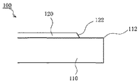
このような表示窓パネル100は、例えば図4に示したように、高透明性を有する透明基板(第1透明体)110を成形機で成形しておき、この透明基板110の一方側面に、粘着材を介して反射防止シート(第2透明体)120を貼着してなるものが広く用いられている。
For example, as shown in FIG. 4, such a
また、透明基板の一方側面と他方側面の両面に、ディップ(浸漬)成形法で反射防止層を設けることで、反射防止効果を高めた表示窓パネルも用いられている。 Moreover, the display window panel which improved the anti-reflective effect by providing an anti-reflective layer by the dip (dipping) molding method in both surfaces of the one side and the other side of a transparent substrate is also used.
さらに透明基板の一方側面と他方側面にそれぞれ異なる光学特性を有する反射防止シートを貼着した表示窓パネル(特許文献1)、また透明基板の一方側面に反射防止効果を有するモスアイ構造のパターンを予め形成しておき、他方側面にはモスアイ構造のパターンとは異なる光学特性を有する反射防止シートを貼着した表示窓パネル(特許文献2)も、本出願人によって既に開発されている。 Further, a display window panel (Patent Document 1) in which antireflection sheets having different optical characteristics are attached to one side surface and the other side surface of the transparent substrate, and a moth-eye structure pattern having an antireflection effect on one side surface of the transparent substrate in advance. A display window panel (Patent Document 2) that has been formed and on which the antireflection sheet having optical characteristics different from the pattern of the moth-eye structure is attached on the other side surface has already been developed by the present applicant.
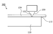
ところで、ディップ(浸漬)成形法を用いて製造された表示窓パネル以外の表示窓パネル100において、透明基板110上に反射防止シート120を貼着する際には、図5に示したように、まず透明基板110上にこれよりも一回り大きな反射防止シート120を貼着し、この後、レーザー130を用いて反射防止シート120を所定の位置でカットするようにしている。反射防止シート120の切断面は傾斜面となり、この傾斜具合はレーザーの照射角度などで調整可能である。図5の符号122は傾斜部分である。
By the way, in the
なお、透明基板110の外周縁部稜線112の位置よりも内側に反射防止シート120の端部が位置するよう、カット時の位置設定がなされている。
The position at the time of cutting is set so that the end of the
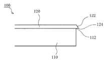
しかしながら、反射防止シート120のカット位置が、何らかの要因でズレが生じてしまった場合には、例えば図6に示したように、透明基板110の外周縁部稜線112の上に反射防止シート120の傾斜部分122の端部が張り出した状態(オーバーハングの状態)で貼着されてしまうことがある。
However, if the cut position of the
このような表示窓パネル100は、反射防止シート120のオーバーハング箇所124に物が引っ掛かってしまい反射防止シートの剥離を引き起したり、この部分に接触して怪我をしてしまう虞が有るため、不良品として扱われている。
Such a
表示窓パネルにおけるオーバーハング有無の検査は、表示窓パネルを目視するなどして行われているが、表示窓パネルが透明であるために不良箇所が見えづらく、不良品を見落とす虞が有るため、更なる検査精度の向上が求められているのが実情である。 Inspection of the presence or absence of overhang in the display window panel is performed by visually observing the display window panel, but because the display window panel is transparent, it is difficult to see the defective part, and there is a risk of overlooking the defective product, The fact is that further improvement in inspection accuracy is required.
本発明はこのような現状に鑑み、少なくとも第1透明体上に第2透明体を配設した透明積層体において、第1透明体の所定の位置に第2透明体が配設されているか否かを高精度に検査することのできる透明積層体の検査方法およびこの検査方法が用いられてなる透明積層体を提供することを目的とする。 In the present invention, in view of such a current situation, whether or not the second transparent body is disposed at a predetermined position of the first transparent body in the transparent laminate in which the second transparent body is disposed at least on the first transparent body. An object of the present invention is to provide a method for inspecting a transparent laminate capable of inspecting the above with high accuracy, and a transparent laminate using the inspection method.
本発明は、前述したような従来技術における課題および目的を達成するために発明されたものであって、
本発明の透明積層体の検査方法は、
板状形態であり一方面の外周端部に面取り部分を有する第1透明体と、前記第1透明体の一方面上に、板状形態であり外周端部に傾斜部分を有する第2透明体が配設されてなる透明積層体において、前記第1透明体の所定位置に第2透明体が配設されているか否かを検査する透明積層体の検査方法であって、
前記透明積層体の検査方法は、
撮像手段で前記第2透明体側の略直上から略直下に向けて前記透明積層体の外周端部を撮像する撮像工程と、
前記撮像工程で撮像された画像の明/暗の違いを元にして、前記第1透明体の面取り部分および第2透明体の傾斜部分の領域を識別し、このそれぞれの領域が識別された場合には第1透明体の所定位置に第2透明体が配設されていると判断し、またこのそれぞれの領域が識別されない場合には第1透明体の所定位置に第2透明体が配設されていないと判断する識別工程と、
を少なくとも有することを特徴とする。
The present invention was invented in order to achieve the problems and objects in the prior art as described above,
The inspection method of the transparent laminate of the present invention is
A first transparent body having a plate shape and having a chamfered portion at the outer peripheral end portion of one surface, and a second transparent body having a plate shape and having an inclined portion at the outer peripheral end portion on one surface of the first transparent body. In the transparent laminated body in which is disposed, the transparent laminated body inspecting method for inspecting whether or not the second transparent body is disposed at a predetermined position of the first transparent body,
The inspection method of the transparent laminate is as follows:
An imaging step of imaging the outer peripheral edge of the transparent laminate from substantially right above the second transparent body side to approximately right below with the imaging means;
When the areas of the chamfered portion of the first transparent body and the inclined portion of the second transparent body are identified based on the difference in brightness / darkness of the image captured in the imaging process, and the respective regions are identified Is determined that the second transparent body is disposed at a predetermined position of the first transparent body, and when the respective areas are not identified, the second transparent body is disposed at the predetermined position of the first transparent body. An identification process for determining that it has not been performed,
It is characterized by having at least.
このような検査方法であれば、第1透明体の面取り部分が他の平坦な部分よりも戻り光が少ない暗部として領域を識別でき、また第2透明体の面取り部分も他の部分よりも戻り光が少ない暗部として領域を識別できる。 With such an inspection method, the chamfered portion of the first transparent body can be identified as a dark portion with less return light than other flat portions, and the chamfered portion of the second transparent body also returns more than the other portions. A region can be identified as a dark part with little light.
このため、良品である透明積層体を略直上から略直下に向けて撮像した場合には両領域が識別でき、不良品である透明積層体を略直上から略直下に向けて撮像した場合には面取り部分と傾斜部分が上下で重なり合うために両領域が上手く識別できないこととなる。この識別を行うことにより透明積層体が不良であるか否かを確実に検査することができる。 For this reason, when imaging a transparent laminate, which is a non-defective product, from approximately directly above to approximately directly below, both areas can be identified, and when a transparent laminate, which is a defective product, is imaged from approximately directly above to approximately immediately below, Since the chamfered portion and the inclined portion overlap each other, the two regions cannot be distinguished well. By performing this identification, it can be reliably inspected whether or not the transparent laminate is defective.
また、本発明の透明積層体の検査方法は、
前記識別工程において、
前記第1透明体の面取り部分および第2透明体の傾斜部分の領域が識別された場合、
さらにそれぞれの領域の位置を元にして、前記第1透明体の外周端部から前記第2透明体の外周端部の位置までの距離を算出し、この距離が予め定められた所定の閾値内にあるとき、前記第1透明体の所定位置に第2透明体が配設されていると判断することを特徴とする。
Moreover, the inspection method of the transparent laminate of the present invention is:
In the identification step,
When areas of the chamfered portion of the first transparent body and the inclined portion of the second transparent body are identified,
Further, based on the position of each region, the distance from the outer peripheral edge of the first transparent body to the position of the outer peripheral edge of the second transparent body is calculated, and this distance falls within a predetermined threshold value. In this case, it is determined that a second transparent body is disposed at a predetermined position of the first transparent body.
このような検査方法であれば、上記した識別工程に加えてさらに第1透明体に対する第
2透明体の配設位置を確実に検査することができる。
With such an inspection method, in addition to the above-described identification step, the arrangement position of the second transparent body relative to the first transparent body can be reliably inspected.
また、本発明の透明積層体の検査方法は、
前記透明積層体を垂直方向から視認した際において、
前記第1透明体の面取り部分の水平方向の距離が、20μm以上であることを特徴とする。
Moreover, the inspection method of the transparent laminate of the present invention is:
When viewing the transparent laminate from the vertical direction,
The horizontal distance of the chamfered portion of the first transparent body is 20 μm or more.
第1透明体の面取り部分がこのような距離を有していれば、撮像工程で撮像した画像において、傾斜部分の領域を確実に識別することができる。このため、透明積層体の検査を確実に行うことができ、不良品があれば確実にそれを見つけることができる。 If the chamfered portion of the first transparent body has such a distance, the region of the inclined portion can be reliably identified in the image captured in the imaging process. For this reason, the transparent laminated body can be inspected reliably, and if there is a defective product, it can be surely found.
また、本発明の透明積層体の検査方法は、
前記傾斜部分が、直線状の角面取りであることを特徴とする。
Moreover, the inspection method of the transparent laminate of the present invention is:
The inclined portion is a linear chamfer.
このように面取り部分が直線状であれば、撮像した際に面取り部分とそうでない部分との領域が画像により鮮明に表れるため、検査に最適な面取り部分の形状として特に好ましい。 If the chamfered portion is a straight line in this way, the region of the chamfered portion and the portion that is not so appear clearly when captured, and this is particularly preferable as the shape of the chamfered portion that is optimal for inspection.
また、本発明の透明積層体の検査方法は、
前記透明積層体を垂直方向から視認した際において、
前記第2透明体の傾斜部分の水平方向の距離が、20μm以上であることを特徴とする。
Moreover, the inspection method of the transparent laminate of the present invention is:
When viewing the transparent laminate from the vertical direction,
The horizontal distance of the inclined portion of the second transparent body is 20 μm or more.
第2透明体の傾斜部分がこのような距離を有していれば、撮像工程で撮像した画像において、傾斜部分の領域を確実に識別することができる。このため、透明積層体の検査を確実に行うことができ、不良品があれば確実にそれを見つけることができる。 If the inclined portion of the second transparent body has such a distance, the region of the inclined portion can be reliably identified in the image captured in the imaging process. For this reason, the transparent laminated body can be inspected reliably, and if there is a defective product, it can be surely found.
また、本発明の透明積層体の検査方法は、
前記第2透明体の外周端部に形成された傾斜部分が、前記第2透明体をレーザーでカットして形成された切断面であることを特徴とする。
Moreover, the inspection method of the transparent laminate of the present invention is:
The inclined portion formed at the outer peripheral end of the second transparent body is a cut surface formed by cutting the second transparent body with a laser.
このように傾斜部分がレーザーによる切断面であれば、傾斜部分の角度も自由に設定可能であり、また切断面の形状もきれいであるため、透明積層体の製造時の使用に好適である。 Thus, if the inclined portion is a laser cut surface, the angle of the inclined portion can be freely set, and the shape of the cut surface is clean, which is suitable for use in manufacturing a transparent laminate.
また、本発明の透明積層体の検査方法は、
前記第1透明体の550〜600nmの波長帯域における分光反射率が、15%以下であることを特徴とする。
Moreover, the inspection method of the transparent laminate of the present invention is:
The spectral reflectance in the wavelength band of 550 to 600 nm of the first transparent body is 15% or less.
このような分光反射率を有する第1透明体であれば、本出願の検査方法を用いることで、第1透明体と第2透明体の領域を識別可能であり、不良品があれば確実にそれを見つけることができる。 If it is a 1st transparent body which has such a spectral reflectance, the area | region of a 1st transparent body and a 2nd transparent body can be identified by using the inspection method of this application, and if there is a defective product, it will be sure You can find it.
また、本発明の透明積層体の検査方法は、
前記第2透明体の550〜600nmの波長帯域における分光反射率が、10%以下であることを特徴とする。
Moreover, the inspection method of the transparent laminate of the present invention is:
The spectral reflectance in the wavelength band of 550 to 600 nm of the second transparent body is 10% or less.
このような分光反射率を有する第2透明体であれば、本出願の検査方法を用いることで、第1透明体と第2透明体の領域を識別可能であり、不良品があれば確実にそれを見つけることができる。 If it is a 2nd transparent body which has such a spectral reflectance, the area | region of a 1st transparent body and a 2nd transparent body can be identified by using the inspection method of this application, and if there is a defective article, it will be sure You can find it.
また、本発明の透明積層体の検査方法は、
前記第1透明体が透明基板であり、
前記第2透明体が反射防止シートであり、
前記透明積層体が、電子機器の表示窓パネルであって、
前記表示窓パネルは、前記透明基板の一方側面に粘着材を介して前記反射防止シートが貼着されてなることを特徴とする。
Moreover, the inspection method of the transparent laminate of the present invention is:
The first transparent body is a transparent substrate;
The second transparent body is an antireflection sheet;
The transparent laminate is a display window panel of an electronic device,
The display window panel is characterized in that the antireflection sheet is adhered to one side surface of the transparent substrate via an adhesive material.
このように透明基板の一方面に粘着材を介して反射防止シートが貼着された表示窓パネルであれば、電子機器の表示部分として好適であり、本検査方法を用いることで、不良な表示窓パネルが誤って出荷されてしまうことを確実に防止することができる。 Thus, if it is a display window panel in which an antireflection sheet is attached to one side of a transparent substrate via an adhesive, it is suitable as a display part of an electronic device, and a defective display can be obtained by using this inspection method. It is possible to reliably prevent the window panel from being shipped accidentally.
また、本発明の透明積層体は、
上記いずれかに記載の透明積層体の検査方法によって、第1透明体に対する第2透明体の配設位置の検査がなされてなることを特徴とする。
The transparent laminate of the present invention is
According to any one of the above-described methods for inspecting a transparent laminate, the arrangement position of the second transparent body with respect to the first transparent body is inspected.
このように本検査方法を用いてなる透明積層体であれば、第1透明体の所定の位置に確実に第2透明体が配設されていることが検査済みであるため、所望のスペックを有する透明積層体として、次工程のユーザーに確実に提供することができる。 Thus, in the case of a transparent laminate using the present inspection method, it has been inspected that the second transparent body is surely disposed at a predetermined position of the first transparent body, so that a desired specification can be obtained. As a transparent laminated body having, it can provide reliably to the user of the next process.
図4に示す従来の表示窓パネルの形状で、図6のように反射防止シート(第2透明体)が透明基板(第1透明体)の端部でオーバーハングした場合、透明基板(第1透明体)の端面の外周縁部稜線は、撮像で光の拡散による明確な暗領域を作り出すことができず、隣接した平坦部の反射光の明の部分と識別できない状態であった。 In the shape of the conventional display window panel shown in FIG. 4, when the antireflection sheet (second transparent body) overhangs at the end of the transparent substrate (first transparent body) as shown in FIG. The edge of the outer peripheral edge of the end face of the transparent body was incapable of creating a clear dark region due to light diffusion during imaging, and was indistinguishable from the bright portion of the reflected light of the adjacent flat portion.
したがって外周縁部稜線が存在せず、反射防止シート(第2透明体)の傾斜部分のみ暗部に見える撮像となり、反射防止シート(第2透明体)が透明基板(第1透明体)をオーバーハングしていることを検査できなかった。 Accordingly, there is no outer peripheral edge, and only the inclined portion of the antireflection sheet (second transparent body) is seen as a dark part, and the antireflection sheet (second transparent body) overhangs the transparent substrate (first transparent body). I couldn't inspect it.
本発明によれば、少なくとも第1透明体上に第2透明体を配設した透明積層体において、第1透明体の面取り部分と第2透明体の傾斜部分とを撮像して、各部分の領域を画像上で識別することで、第1透明体の所定の位置に第2透明体が配設されているか否かを高精度に検査することができる。 According to the present invention, in the transparent laminate in which the second transparent body is disposed on at least the first transparent body, the chamfered portion of the first transparent body and the inclined portion of the second transparent body are imaged, By identifying the region on the image, it is possible to inspect whether or not the second transparent body is disposed at a predetermined position of the first transparent body.
本発明は、第1透明体の一方面に第2透明体を配設してなる透明積層体において、第1透明体の所定の位置に第2透明体が配設されているか否かを検査する検査方法、およびこの検査方法を用いてなる透明積層体である。 The present invention inspects whether or not the second transparent body is disposed at a predetermined position of the first transparent body in the transparent laminated body in which the second transparent body is disposed on one surface of the first transparent body. And a transparent laminate using this inspection method.
以下、本発明の検査方法について、透明積層体の実施形態の一つとして、例えば電子機器の表示部分に用いられる表示窓パネルを例にして説明を行う。 Hereinafter, the inspection method of the present invention will be described by taking a display window panel used in a display portion of an electronic device as an example as an embodiment of a transparent laminate.
また、本明細書中で「面取り部分」とは、面と面とが交わった部分の角部に加工が施された部分、および板状形態の端部を斜めに切り落とされた部分であり、その形状を限定するものではないものである。 Further, in the present specification, the “chamfered portion” is a portion processed at the corner of the portion where the surface intersects the surface, and a portion obtained by obliquely cutting off the end of the plate-like form, The shape is not limited.
さらに「傾斜部分」とは、直線状の傾斜面をはじめ、曲面カーブをも含んだ意味で用いられており、端部から端部までの高低差があればその形状を限定するものではないものである。 Furthermore, “inclined portion” is used to mean a curved surface including a straight inclined surface, and the shape is not limited as long as there is a height difference from end to end. It is.
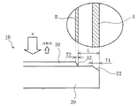
透明積層体の実施形態の一つである図1に示した表示窓パネル10は、板状形態であり一方面の外周端部に面取り部分22を有する透明基板20と、この透明基板20の一方面上に、板状形態であり外周端部に傾斜部分32を有する反射防止シート30が粘着材を介して貼着されてなるものである。
The
透明基板20の面取り部分22は、例えば電子機器の表示部分の表面側に位置するため、電子機器を使用するユーザーが角部分で怪我をしたりしないように予め角を落としてなる部分である。
Since the chamfered
反射防止シート30の傾斜部分32は、透明基板20から反射防止シート30が剥がれ難くするためのものである。傾斜部分32の形成方法としては、背景技術の欄で説明したように、レーザーによる反射防止シート30のカットの際、レーザーの照射角度によってその傾斜部分32が形成される。なお、後述するように傾斜部分32が検査で必要な箇所となるため、切断部分が傾斜されるのであれば、レーザー以外に切断刃を用いるなど特に切断手段は限定されないものである。
The
このような透明基板20の材質としては、高透明性を有する合成樹脂を用いることができ、例えばポリカーボネート(PC)またはポリメチルメタクリレイト(PMMA)またはシクロオレフィンポリマーを用いることが好ましい。
As a material for such a
なお、高透明性を有する合成樹脂の選定については、製品として求められるスペックに合わせて適宜選択すれば良いものであるが、株式会社日立ハイテクノロジーズ製の分光光度計U−3010を用いた1mm厚みの基板測定(波長帯域550〜600nm)で、分光反射率15%以下のものであれば、視認性を良好に維持するうえでも好ましい。 In addition, about selection of the synthetic resin which has high transparency, what is necessary is just to select suitably according to the specification calculated | required as a product, but 1 mm thickness using the spectrophotometer U-3010 by Hitachi High-Technologies Corporation. In the substrate measurement (wavelength band of 550 to 600 nm), a spectral reflectance of 15% or less is preferable for maintaining good visibility.
一方、反射防止シート30としては、製品として求められるスペックに合わせて適宜市販品の中から選択して使用することが好ましく、例えば反射防止層(図示せず)とハードコート層(図示せず)と基材層(図示せず)とが積層され、片面に粘着材層を有する日油株式会社製の反射防止シート,日本化薬株式会社製の反射防止シートなどを用いることが好ましく、波長帯域550〜600nmで分光反射率10%以下のものが視認性を良好に維持するうえで好ましい。 On the other hand, the antireflection sheet 30 is preferably selected from commercially available products according to the specifications required for the product. For example, an antireflection layer (not shown) and a hard coat layer (not shown) are used. It is preferable to use an antireflective sheet manufactured by NOF Corporation, an antireflective sheet manufactured by Nippon Kayaku Co., Ltd., etc. having a pressure-sensitive adhesive layer on one side, and a wavelength band. Those having a spectral reflectance of 10% or less at 550 to 600 nm are preferable for maintaining good visibility.
このような表示窓パネル10は、例えば電子機器の表示部分に用いられ、これにより表示部分を良好に保護しつつ、視認性も良好に維持することができる。
Such a
ここで透明基板20上に貼着された反射防止シート30は、透明基板20の外周端部に形成された面取り部分22よりも内側に、その外周端部に形成された傾斜部分32の端部が位置するように位置決めされている。
Here, the antireflection sheet 30 adhered on the
このようにして構成される表示窓パネル10において、透明基板20の所定の位置で反射防止シート30が確実にカットされているか否かの検査は、まず撮像手段(図示せず)で反射防止シート30側の略直上から略直下に向けて表示窓パネル10の外周端部を撮像する。
In the
すると、図1の楕円で囲われた画像イメージのように、透明基板20の面取り部分22と、反射防止シート30の傾斜部分(切断面)32が他の平坦な部分よりも暗く表示されることとなる。これは、表示窓パネル10の略直上から略直下に向けて光を照射した場合、表示窓パネル10の平坦部からは正反射光が反射するが、透明基板20の面取り部分22および反射防止シート30の傾斜部分32では光が拡散されるため、殆ど反射しないことになる。このため、撮像時に表示窓パネル10に照射された光の反射具合の違いが、画像に明/暗の違いとして現れたものである。
Then, like the image image surrounded by the ellipse in FIG. 1, the chamfered
なお、図1に示した表示窓パネル10は良品であり、このように良品の場合には画像として透明基板20の面取り部分22の領域Aと、反射防止シート30の傾斜部分32の領域Bの2つの領域が存在することとなる。
The
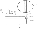
これに対して図2に示したように不良品である表示窓パネル10は、透明基板20の面取り部分22上に反射防止シート30の傾斜部分32が位置し、反射防止シート30がオーバーハング箇所34を有するため、この不良品である表示窓パネル10を撮像した画像は、反射防止シート30の傾斜部分32が透明基板20の面取り部分22上に重なり合ってしまい、図1のように透明基板20の面取り部分22の領域Aと、反射防止シート30の傾斜部分32の領域Bの2つの領域が確認できず、2つが合体した1つの領域Cが確認されるだけである。
On the other hand, as shown in FIG. 2, in the
したがって、このように表示窓パネル10の略直上から略直下に向けて撮像した画像を用いて行われる表示窓パネル10の検査では、透明基板20の面取り部分22の領域Aと反射防止シート30の傾斜部分32の領域Bの2つの領域が確認された場合には、明らかに透明基板20の面取り部分22の内側に反射防止シート30の傾斜部分32の端部が位置しており良品であると判断でき、透明基板20の面取り部分22の領域Aと反射防止シート30の傾斜部分32の領域Bの2つの領域が確認されない場合には、透明基板20の面取り部分22上に反射防止シート30の傾斜部分32の端部が位置しており不良品であると判断することができる。
Therefore, in the inspection of the
なお、透明基板20の面取り部分22の領域Aと反射防止シート30の傾斜部分32の領域Bの2つの領域が確認された場合には、透明基板20の面取り部分22端部から反射防止シート30の傾斜部分32の端部までの距離Lが、予め設定された閾値内であるか否かを、画像中の面取り部分22の領域Aの端部の位置と、傾斜部分32の領域Bの端部の位置を元にして求めることで、寸法範囲内に表示窓パネル10ができているか否かを確認することができ、これによりこの寸法範囲内に入らなかった表示窓パネル10について最終的な不良品と判断することができる。
In addition, when the two areas of the area A of the chamfered
ここで透明基板20の面取り部分22の水平方向の幅T1、および反射防止シート30の傾斜部分32の水平方向の幅T2としては、それぞれ20μm以上であることが好ましい。この数値よりも小さい場合には、撮像した画像において、透明基板20の面取り部分
22および反射防止シート30の傾斜部分32のそれぞれの領域A,Bを識別するために非常に高価で高精度な撮像機と照明を使い、且つ時間の掛かる検査が必要となり、コストパフォーマンスが悪い。このため、この幅は、上記したような幅を持っていることが好ましい。
Here, the horizontal width T1 of the chamfered
また反射率が低い透明基板20および更に反射率が低い反射防止シート30の検査のため、画像検査に用いる照明には平行光を用いて画像の明暗差を出すことが好ましい。
Further, for the inspection of the
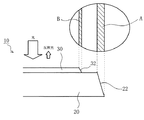
さらに透明基板20の面取り部分22は、直線状の傾斜面であることが好ましく、図1に示したような形態や図3に示したような形態であれば、面取り部分22の領域Aが画像に明/暗の違いとして明確に現れる。
Furthermore, it is preferable that the chamfered
しかしながら、面取り部分22の形態としては、これに限定されるものではなく、球状としたり凹部とするなど、要は表示窓パネル10を略直上から略直下に向けて撮像した際に、透明基板20の面取り部分22が画像に明/暗の違いとして現れるか否かが重要であるため、光を拡散させて反射率が平坦部分と異なるようにしさえすれば、如何なる形態でも良いものである。
However, the form of the chamfered
以上、本発明の検査方法の好ましい実施の態様について、図1〜図3に示した形態の表示窓パネルを用いて説明したが、本発明はこのような形態の表示パネルに限定されるものではなく、例えば背景技術の欄に記載したように、透明基板(第1透明体)の一方面と他方面にそれぞれ異なる光学特性を有する反射防止シート(第2透明体)を貼着した表示窓パネル(透明積層体)、また透明基板(第1透明体)の成形時に、透明基板(第1透明体)の一方面に反射防止効果を有するモスアイ構造のパターンを形成しておき、透明基板(第1透明体)の他方面にのみ、反射防止シート(第2透明体)を貼着した表示窓パネル(透明積層体)の検査にも適用可能な汎用性の高い検査方法であり、表示窓パネル(透明積層体)の形態に合わせて変更や追加が可能であることは当然のことである。 The preferred embodiment of the inspection method of the present invention has been described above using the display window panel of the form shown in FIGS. 1 to 3, but the present invention is not limited to such a form of display panel. For example, as described in the background art section, a display window panel in which an antireflection sheet (second transparent body) having different optical characteristics is attached to one side and the other side of a transparent substrate (first transparent body). When the transparent substrate (first transparent body) is molded, a moth-eye structure pattern having an antireflection effect is formed on one surface of the transparent substrate (first transparent body). It is a highly versatile inspection method that can be applied to inspection of display window panels (transparent laminates) with an antireflection sheet (second transparent body) attached only to the other side of one transparent body. Change according to the form of (transparent laminate) That pressure is possible is a matter of course.
10・・・表示窓パネル
20・・・透明基板
22・・・面取り部分
30・・・反射防止シート
32・・・傾斜部分
34・・・オーバーハング箇所
A・・・透明基板の面取り部分の領域
B・・・反射防止シートの傾斜部分の領域
C・・・合体した1つの領域
T1・・透明基板の面取り部分の水平方向の幅
T2・・反射防止シートの傾斜部分の水平方向の幅
L・・・透明基板の面取り部分の端部から反射防止シートの傾斜部分の端部までの距離
100・・・表示窓パネル
110・・・透明基板
112・・・外周縁部稜線
120・・・反射防止シート
122・・・傾斜部分(切断面)
124・・・オーバーハング箇所
130・・・レーザー
DESCRIPTION OF
124 ... Overhanging
Claims (10)
前記透明積層体の検査方法は、
撮像手段で前記第2透明体側の略直上から略直下に向けて前記透明積層体の外周端部を撮像する撮像工程と、
前記撮像工程で撮像された画像の明/暗の違いを元にして、前記第1透明体の面取り部分および第2透明体の傾斜部分の領域を識別し、このそれぞれの領域が識別された場合には第1透明体の所定位置に第2透明体が配設されていると判断し、またこのそれぞれの領域が識別されない場合には第1透明体の所定位置に第2透明体が配設されていないと判断する識別工程と、
を少なくとも有することを特徴とする透明積層体の検査方法。 A first transparent body having a plate shape and having a chamfered portion at the outer peripheral end portion of one surface, and a second transparent body having a plate shape and having an inclined portion at the outer peripheral end portion on one surface of the first transparent body. In the transparent laminated body in which is disposed, the transparent laminated body inspecting method for inspecting whether or not the second transparent body is disposed at a predetermined position of the first transparent body,
The inspection method of the transparent laminate is as follows:
An imaging step of imaging the outer peripheral edge of the transparent laminate from substantially right above the second transparent body side to approximately right below with the imaging means;
When the areas of the chamfered portion of the first transparent body and the inclined portion of the second transparent body are identified based on the difference in brightness / darkness of the image captured in the imaging process, and the respective regions are identified Is determined that the second transparent body is disposed at a predetermined position of the first transparent body, and when the respective areas are not identified, the second transparent body is disposed at the predetermined position of the first transparent body. An identification process for determining that it has not been performed,
A method for inspecting a transparent laminate, comprising:
前記第1透明体の面取り部分および第2透明体の傾斜部分の領域が識別された場合、
さらにそれぞれの領域の位置を元にして、前記第1透明体の外周端部から前記第2透明体の外周端部の位置までの距離を算出し、この距離が予め定められた所定の閾値内にあるとき、前記第1透明体の所定位置に第2透明体が配設されていると判断することを特徴とする請求項1に記載の透明積層体の検査方法。 In the identification step,
When areas of the chamfered portion of the first transparent body and the inclined portion of the second transparent body are identified,
Further, based on the position of each region, the distance from the outer peripheral edge of the first transparent body to the position of the outer peripheral edge of the second transparent body is calculated, and this distance falls within a predetermined threshold value. 2. The method for inspecting a transparent laminate according to claim 1, wherein the second transparent body is determined to be disposed at a predetermined position of the first transparent body.
前記第1透明体の面取り部分の水平方向の距離が、20μm以上であることを特徴とする請求項1または2に記載の透明積層体の検査方法。 When viewing the transparent laminate from the vertical direction,
The method for inspecting a transparent laminate according to claim 1 or 2, wherein a distance in a horizontal direction of the chamfered portion of the first transparent body is 20 µm or more.
前記第2透明体の傾斜部分の水平方向の距離が、20μm以上であることを特徴とする請求項1から4のいずれかに記載の透明積層体の検査方法。 When viewing the transparent laminate from the vertical direction,
The method for inspecting a transparent laminate according to any one of claims 1 to 4, wherein a distance in a horizontal direction of the inclined portion of the second transparent body is 20 µm or more.
前記第2透明体が反射防止シートであり、
前記透明積層体が、電子機器の表示窓パネルであって、
前記表示窓パネルは、前記透明基板の一方側面に粘着材を介して前記反射防止シートが貼着されてなることを特徴とする請求項1から8のいずれかに記載の透明積層体の検査方法。 The first transparent body is a transparent substrate;
The second transparent body is an antireflection sheet;
The transparent laminate is a display window panel of an electronic device,
The method for inspecting a transparent laminate according to any one of claims 1 to 8, wherein the display window panel has the antireflection sheet attached to one side surface of the transparent substrate via an adhesive material. .
Priority Applications (1)
| Application Number | Priority Date | Filing Date | Title |
|---|---|---|---|
| JP2010107461A JP2011237223A (en) | 2010-05-07 | 2010-05-07 | Inspection method for transparent laminate and transparent laminate subjected to the inspection method |
Applications Claiming Priority (1)
| Application Number | Priority Date | Filing Date | Title |
|---|---|---|---|
| JP2010107461A JP2011237223A (en) | 2010-05-07 | 2010-05-07 | Inspection method for transparent laminate and transparent laminate subjected to the inspection method |
Publications (1)
| Publication Number | Publication Date |
|---|---|
| JP2011237223A true JP2011237223A (en) | 2011-11-24 |
Family
ID=45325381
Family Applications (1)
| Application Number | Title | Priority Date | Filing Date |
|---|---|---|---|
| JP2010107461A Pending JP2011237223A (en) | 2010-05-07 | 2010-05-07 | Inspection method for transparent laminate and transparent laminate subjected to the inspection method |
Country Status (1)
| Country | Link |
|---|---|
| JP (1) | JP2011237223A (en) |
Cited By (2)
| Publication number | Priority date | Publication date | Assignee | Title |
|---|---|---|---|---|
| WO2014057881A1 (en) * | 2012-10-12 | 2014-04-17 | 住友化学株式会社 | Detection apparatus, method for manufacturing optical member-bonded body, and method for manufacturing optical member-bonded body |
| JP2017116264A (en) * | 2015-12-21 | 2017-06-29 | 日本電気硝子株式会社 | Inspection method and inspection device of glass film laminate |
-
2010
- 2010-05-07 JP JP2010107461A patent/JP2011237223A/en active Pending
Cited By (3)
| Publication number | Priority date | Publication date | Assignee | Title |
|---|---|---|---|---|
| WO2014057881A1 (en) * | 2012-10-12 | 2014-04-17 | 住友化学株式会社 | Detection apparatus, method for manufacturing optical member-bonded body, and method for manufacturing optical member-bonded body |
| JPWO2014057881A1 (en) * | 2012-10-12 | 2016-09-05 | 住友化学株式会社 | Detecting device, optical member bonded body manufacturing apparatus, and optical member bonded body manufacturing method |
| JP2017116264A (en) * | 2015-12-21 | 2017-06-29 | 日本電気硝子株式会社 | Inspection method and inspection device of glass film laminate |
Similar Documents
| Publication | Publication Date | Title |
|---|---|---|
| JP7668083B2 (en) | Visual inspection method and visual inspection device | |
| CN107241467A (en) | electronic device | |
| JP2012167975A (en) | Defect inspection method and defect inspection device | |
| JP5027946B1 (en) | Inspection system | |
| JP2017090360A (en) | Surface inspection apparatus and surface inspection method | |
| TWI850630B (en) | Display panel | |
| US20120133761A1 (en) | Uneven area inspection system | |
| TW201842327A (en) | Cover glass inspection apparatus | |
| JP4950951B2 (en) | Light transmissive film defect detection device and light transmissive film cutting device | |
| TW201602515A (en) | Method and system for measuring thickness of glass article | |
| JP5540849B2 (en) | Metal defect detection method and defect detection apparatus | |
| JP4921597B1 (en) | Liquid crystal display panel continuous manufacturing system, liquid crystal display panel continuous manufacturing method, inspection apparatus and inspection method | |
| JP2011237223A (en) | Inspection method for transparent laminate and transparent laminate subjected to the inspection method | |
| JP2009103487A (en) | PTP packaging machine | |
| TW382061B (en) | Carrier for substrate and defect inspection apparatus for substrate | |
| JP2001116925A (en) | Optical sheet inspection method | |
| KR102927634B1 (en) | Method of manufacturing display device | |
| JP2008514922A (en) | Light control film inspection system and inspection method, and light control film manufacturing method | |
| JPWO2017115695A1 (en) | Optical member and defect inspection method for antireflection member | |
| JP2012247343A (en) | Defect inspection method of antireflection film and defect inspection apparatus | |
| JP5533086B2 (en) | Outline detection apparatus and outline detection method | |
| JP5391238B2 (en) | Dot pattern printing light guide plate | |
| JPH07229708A (en) | Sticker position inspecting device | |
| TWM457889U (en) | Panel defect detection device | |
| JP2004069432A (en) | Inspection method and apparatus for transparent body |