JP2011237267A - Leakage test method and leakage test apparatus of iodine filter - Google Patents
Leakage test method and leakage test apparatus of iodine filter Download PDFInfo
- Publication number
- JP2011237267A JP2011237267A JP2010108638A JP2010108638A JP2011237267A JP 2011237267 A JP2011237267 A JP 2011237267A JP 2010108638 A JP2010108638 A JP 2010108638A JP 2010108638 A JP2010108638 A JP 2010108638A JP 2011237267 A JP2011237267 A JP 2011237267A
- Authority
- JP
- Japan
- Prior art keywords
- iodine
- fluorine
- filter
- containing reagent
- iodine filter
- Prior art date
- Legal status (The legal status is an assumption and is not a legal conclusion. Google has not performed a legal analysis and makes no representation as to the accuracy of the status listed.)
- Granted
Links
- ZCYVEMRRCGMTRW-UHFFFAOYSA-N 7553-56-2 Chemical compound [I] ZCYVEMRRCGMTRW-UHFFFAOYSA-N 0.000 title claims abstract description 242
- 229910052740 iodine Inorganic materials 0.000 title claims abstract description 242
- 239000011630 iodine Substances 0.000 title claims abstract description 242
- 238000012360 testing method Methods 0.000 title claims abstract description 56
- 238000010998 test method Methods 0.000 title claims description 26
- YCKRFDGAMUMZLT-UHFFFAOYSA-N Fluorine atom Chemical compound [F] YCKRFDGAMUMZLT-UHFFFAOYSA-N 0.000 claims abstract description 113
- 229910052731 fluorine Inorganic materials 0.000 claims abstract description 113
- 239000011737 fluorine Substances 0.000 claims abstract description 113
- 239000003153 chemical reaction reagent Substances 0.000 claims abstract description 108
- 230000002285 radioactive effect Effects 0.000 claims abstract description 46
- 239000003463 adsorbent Substances 0.000 claims abstract description 30
- 238000011144 upstream manufacturing Methods 0.000 claims abstract description 17
- 239000000460 chlorine Substances 0.000 claims abstract description 12
- ZAMOUSCENKQFHK-UHFFFAOYSA-N Chlorine atom Chemical compound [Cl] ZAMOUSCENKQFHK-UHFFFAOYSA-N 0.000 claims abstract description 11
- 229910052801 chlorine Inorganic materials 0.000 claims abstract description 11
- 239000007789 gas Substances 0.000 claims description 112
- 238000009835 boiling Methods 0.000 claims description 24
- OKTJSMMVPCPJKN-UHFFFAOYSA-N Carbon Chemical compound [C] OKTJSMMVPCPJKN-UHFFFAOYSA-N 0.000 claims description 21
- 150000001875 compounds Chemical class 0.000 claims description 15
- IJGRMHOSHXDMSA-UHFFFAOYSA-N Atomic nitrogen Chemical compound N#N IJGRMHOSHXDMSA-UHFFFAOYSA-N 0.000 claims description 10
- QVGXLLKOCUKJST-UHFFFAOYSA-N atomic oxygen Chemical compound [O] QVGXLLKOCUKJST-UHFFFAOYSA-N 0.000 claims description 5
- 229910052799 carbon Inorganic materials 0.000 claims description 5
- 239000001257 hydrogen Substances 0.000 claims description 5
- 229910052739 hydrogen Inorganic materials 0.000 claims description 5
- 229910052757 nitrogen Inorganic materials 0.000 claims description 5
- 239000001301 oxygen Substances 0.000 claims description 5
- 229910052760 oxygen Inorganic materials 0.000 claims description 5
- 125000004435 hydrogen atom Chemical class [H]* 0.000 claims 2
- 238000005259 measurement Methods 0.000 abstract description 10
- 238000000034 method Methods 0.000 abstract description 6
- 238000005070 sampling Methods 0.000 description 10
- 238000001179 sorption measurement Methods 0.000 description 10
- XLYOFNOQVPJJNP-ZSJDYOACSA-N Heavy water Chemical compound [2H]O[2H] XLYOFNOQVPJJNP-ZSJDYOACSA-N 0.000 description 8
- 239000000203 mixture Substances 0.000 description 8
- INQOMBQAUSQDDS-UHFFFAOYSA-N iodomethane Chemical compound IC INQOMBQAUSQDDS-UHFFFAOYSA-N 0.000 description 6
- BQCADISMDOOEFD-UHFFFAOYSA-N Silver Chemical compound [Ag] BQCADISMDOOEFD-UHFFFAOYSA-N 0.000 description 5
- 238000010586 diagram Methods 0.000 description 5
- 238000010438 heat treatment Methods 0.000 description 5
- 229910052709 silver Inorganic materials 0.000 description 5
- 239000004332 silver Substances 0.000 description 5
- 239000000463 material Substances 0.000 description 4
- IMNIMPAHZVJRPE-UHFFFAOYSA-N triethylenediamine Chemical compound C1CN2CCN1CC2 IMNIMPAHZVJRPE-UHFFFAOYSA-N 0.000 description 4
- 238000009423 ventilation Methods 0.000 description 4
- 229910021536 Zeolite Inorganic materials 0.000 description 3
- 238000001514 detection method Methods 0.000 description 3
- HNPSIPDUKPIQMN-UHFFFAOYSA-N dioxosilane;oxo(oxoalumanyloxy)alumane Chemical compound O=[Si]=O.O=[Al]O[Al]=O HNPSIPDUKPIQMN-UHFFFAOYSA-N 0.000 description 3
- 238000011156 evaluation Methods 0.000 description 3
- PNDPGZBMCMUPRI-UHFFFAOYSA-N iodine Chemical compound II PNDPGZBMCMUPRI-UHFFFAOYSA-N 0.000 description 3
- 239000010457 zeolite Substances 0.000 description 3
- -1 Alternatively Chemical compound 0.000 description 2
- 238000004378 air conditioning Methods 0.000 description 2
- 239000000470 constituent Substances 0.000 description 2
- 150000002431 hydrogen Chemical class 0.000 description 2
- 238000009434 installation Methods 0.000 description 2
- 239000007788 liquid Substances 0.000 description 2
- 241000264877 Hippospongia communis Species 0.000 description 1
- UFHFLCQGNIYNRP-UHFFFAOYSA-N Hydrogen Chemical compound [H][H] UFHFLCQGNIYNRP-UHFFFAOYSA-N 0.000 description 1
- CBENFWSGALASAD-UHFFFAOYSA-N Ozone Chemical compound [O-][O+]=O CBENFWSGALASAD-UHFFFAOYSA-N 0.000 description 1
- VYPSYNLAJGMNEJ-UHFFFAOYSA-N Silicium dioxide Chemical compound O=[Si]=O VYPSYNLAJGMNEJ-UHFFFAOYSA-N 0.000 description 1
- SWJBITNFDYHWBU-UHFFFAOYSA-N [I].[I] Chemical compound [I].[I] SWJBITNFDYHWBU-UHFFFAOYSA-N 0.000 description 1
- PNEYBMLMFCGWSK-UHFFFAOYSA-N aluminium oxide Inorganic materials [O-2].[O-2].[O-2].[Al+3].[Al+3] PNEYBMLMFCGWSK-UHFFFAOYSA-N 0.000 description 1
- 230000006378 damage Effects 0.000 description 1
- 230000005264 electron capture Effects 0.000 description 1
- 238000001704 evaporation Methods 0.000 description 1
- 239000000835 fiber Substances 0.000 description 1
- NBVXSUQYWXRMNV-UHFFFAOYSA-N fluoromethane Chemical compound FC NBVXSUQYWXRMNV-UHFFFAOYSA-N 0.000 description 1
- 239000008187 granular material Substances 0.000 description 1
- 150000002497 iodine compounds Chemical class 0.000 description 1
- 229910052680 mordenite Inorganic materials 0.000 description 1
- 239000008188 pellet Substances 0.000 description 1
- 238000012545 processing Methods 0.000 description 1
- 238000012958 reprocessing Methods 0.000 description 1
- 239000000741 silica gel Substances 0.000 description 1
- 229910002027 silica gel Inorganic materials 0.000 description 1
- 239000007921 spray Substances 0.000 description 1
- 239000000126 substance Substances 0.000 description 1
- XLYOFNOQVPJJNP-UHFFFAOYSA-N water Substances O XLYOFNOQVPJJNP-UHFFFAOYSA-N 0.000 description 1
Images



Classifications
-
- G—PHYSICS
- G21—NUCLEAR PHYSICS; NUCLEAR ENGINEERING
- G21F—PROTECTION AGAINST X-RADIATION, GAMMA RADIATION, CORPUSCULAR RADIATION OR PARTICLE BOMBARDMENT; TREATING RADIOACTIVELY CONTAMINATED MATERIAL; DECONTAMINATION ARRANGEMENTS THEREFOR
- G21F9/00—Treating radioactively contaminated material; Decontamination arrangements therefor
- G21F9/02—Treating gases
-
- B—PERFORMING OPERATIONS; TRANSPORTING
- B01—PHYSICAL OR CHEMICAL PROCESSES OR APPARATUS IN GENERAL
- B01D—SEPARATION
- B01D53/00—Separation of gases or vapours; Recovering vapours of volatile solvents from gases; Chemical or biological purification of waste gases, e.g. engine exhaust gases, smoke, fumes, flue gases, aerosols
- B01D53/22—Separation of gases or vapours; Recovering vapours of volatile solvents from gases; Chemical or biological purification of waste gases, e.g. engine exhaust gases, smoke, fumes, flue gases, aerosols by diffusion
-
- B—PERFORMING OPERATIONS; TRANSPORTING
- B01—PHYSICAL OR CHEMICAL PROCESSES OR APPARATUS IN GENERAL
- B01D—SEPARATION
- B01D65/00—Accessories or auxiliary operations, in general, for separation processes or apparatus using semi-permeable membranes
- B01D65/10—Testing of membranes or membrane apparatus; Detecting or repairing leaks
- B01D65/104—Detection of leaks in membrane apparatus or modules
-
- B—PERFORMING OPERATIONS; TRANSPORTING
- B01—PHYSICAL OR CHEMICAL PROCESSES OR APPARATUS IN GENERAL
- B01J—CHEMICAL OR PHYSICAL PROCESSES, e.g. CATALYSIS OR COLLOID CHEMISTRY; THEIR RELEVANT APPARATUS
- B01J20/00—Solid sorbent compositions or filter aid compositions; Sorbents for chromatography; Processes for preparing, regenerating or reactivating thereof
- B01J20/02—Solid sorbent compositions or filter aid compositions; Sorbents for chromatography; Processes for preparing, regenerating or reactivating thereof comprising inorganic material
- B01J20/0203—Solid sorbent compositions or filter aid compositions; Sorbents for chromatography; Processes for preparing, regenerating or reactivating thereof comprising inorganic material comprising compounds of metals not provided for in B01J20/04
- B01J20/0233—Compounds of Cu, Ag, Au
-
- B—PERFORMING OPERATIONS; TRANSPORTING
- B01—PHYSICAL OR CHEMICAL PROCESSES OR APPARATUS IN GENERAL
- B01J—CHEMICAL OR PHYSICAL PROCESSES, e.g. CATALYSIS OR COLLOID CHEMISTRY; THEIR RELEVANT APPARATUS
- B01J20/00—Solid sorbent compositions or filter aid compositions; Sorbents for chromatography; Processes for preparing, regenerating or reactivating thereof
- B01J20/02—Solid sorbent compositions or filter aid compositions; Sorbents for chromatography; Processes for preparing, regenerating or reactivating thereof comprising inorganic material
- B01J20/10—Solid sorbent compositions or filter aid compositions; Sorbents for chromatography; Processes for preparing, regenerating or reactivating thereof comprising inorganic material comprising silica or silicate
- B01J20/103—Solid sorbent compositions or filter aid compositions; Sorbents for chromatography; Processes for preparing, regenerating or reactivating thereof comprising inorganic material comprising silica or silicate comprising silica
-
- B—PERFORMING OPERATIONS; TRANSPORTING
- B01—PHYSICAL OR CHEMICAL PROCESSES OR APPARATUS IN GENERAL
- B01J—CHEMICAL OR PHYSICAL PROCESSES, e.g. CATALYSIS OR COLLOID CHEMISTRY; THEIR RELEVANT APPARATUS
- B01J20/00—Solid sorbent compositions or filter aid compositions; Sorbents for chromatography; Processes for preparing, regenerating or reactivating thereof
- B01J20/02—Solid sorbent compositions or filter aid compositions; Sorbents for chromatography; Processes for preparing, regenerating or reactivating thereof comprising inorganic material
- B01J20/10—Solid sorbent compositions or filter aid compositions; Sorbents for chromatography; Processes for preparing, regenerating or reactivating thereof comprising inorganic material comprising silica or silicate
- B01J20/16—Alumino-silicates
- B01J20/165—Natural alumino-silicates, e.g. zeolites
-
- B—PERFORMING OPERATIONS; TRANSPORTING
- B01—PHYSICAL OR CHEMICAL PROCESSES OR APPARATUS IN GENERAL
- B01J—CHEMICAL OR PHYSICAL PROCESSES, e.g. CATALYSIS OR COLLOID CHEMISTRY; THEIR RELEVANT APPARATUS
- B01J20/00—Solid sorbent compositions or filter aid compositions; Sorbents for chromatography; Processes for preparing, regenerating or reactivating thereof
- B01J20/02—Solid sorbent compositions or filter aid compositions; Sorbents for chromatography; Processes for preparing, regenerating or reactivating thereof comprising inorganic material
- B01J20/10—Solid sorbent compositions or filter aid compositions; Sorbents for chromatography; Processes for preparing, regenerating or reactivating thereof comprising inorganic material comprising silica or silicate
- B01J20/16—Alumino-silicates
- B01J20/18—Synthetic zeolitic molecular sieves
- B01J20/186—Chemical treatments in view of modifying the properties of the sieve, e.g. increasing the stability or the activity, also decreasing the activity
-
- B—PERFORMING OPERATIONS; TRANSPORTING
- B01—PHYSICAL OR CHEMICAL PROCESSES OR APPARATUS IN GENERAL
- B01J—CHEMICAL OR PHYSICAL PROCESSES, e.g. CATALYSIS OR COLLOID CHEMISTRY; THEIR RELEVANT APPARATUS
- B01J20/00—Solid sorbent compositions or filter aid compositions; Sorbents for chromatography; Processes for preparing, regenerating or reactivating thereof
- B01J20/02—Solid sorbent compositions or filter aid compositions; Sorbents for chromatography; Processes for preparing, regenerating or reactivating thereof comprising inorganic material
- B01J20/20—Solid sorbent compositions or filter aid compositions; Sorbents for chromatography; Processes for preparing, regenerating or reactivating thereof comprising inorganic material comprising free carbon; comprising carbon obtained by carbonising processes
-
- B—PERFORMING OPERATIONS; TRANSPORTING
- B01—PHYSICAL OR CHEMICAL PROCESSES OR APPARATUS IN GENERAL
- B01J—CHEMICAL OR PHYSICAL PROCESSES, e.g. CATALYSIS OR COLLOID CHEMISTRY; THEIR RELEVANT APPARATUS
- B01J20/00—Solid sorbent compositions or filter aid compositions; Sorbents for chromatography; Processes for preparing, regenerating or reactivating thereof
- B01J20/28—Solid sorbent compositions or filter aid compositions; Sorbents for chromatography; Processes for preparing, regenerating or reactivating thereof characterised by their form or physical properties
- B01J20/28014—Solid sorbent compositions or filter aid compositions; Sorbents for chromatography; Processes for preparing, regenerating or reactivating thereof characterised by their form or physical properties characterised by their form
- B01J20/28042—Shaped bodies; Monolithic structures
- B01J20/28045—Honeycomb or cellular structures; Solid foams or sponges
-
- B—PERFORMING OPERATIONS; TRANSPORTING
- B01—PHYSICAL OR CHEMICAL PROCESSES OR APPARATUS IN GENERAL
- B01J—CHEMICAL OR PHYSICAL PROCESSES, e.g. CATALYSIS OR COLLOID CHEMISTRY; THEIR RELEVANT APPARATUS
- B01J20/00—Solid sorbent compositions or filter aid compositions; Sorbents for chromatography; Processes for preparing, regenerating or reactivating thereof
- B01J20/30—Processes for preparing, regenerating, or reactivating
- B01J20/3007—Moulding, shaping or extruding
-
- B—PERFORMING OPERATIONS; TRANSPORTING
- B01—PHYSICAL OR CHEMICAL PROCESSES OR APPARATUS IN GENERAL
- B01J—CHEMICAL OR PHYSICAL PROCESSES, e.g. CATALYSIS OR COLLOID CHEMISTRY; THEIR RELEVANT APPARATUS
- B01J20/00—Solid sorbent compositions or filter aid compositions; Sorbents for chromatography; Processes for preparing, regenerating or reactivating thereof
- B01J20/30—Processes for preparing, regenerating, or reactivating
- B01J20/32—Impregnating or coating ; Solid sorbent compositions obtained from processes involving impregnating or coating
- B01J20/3202—Impregnating or coating ; Solid sorbent compositions obtained from processes involving impregnating or coating characterised by the carrier, support or substrate used for impregnation or coating
- B01J20/3204—Inorganic carriers, supports or substrates
-
- B—PERFORMING OPERATIONS; TRANSPORTING
- B01—PHYSICAL OR CHEMICAL PROCESSES OR APPARATUS IN GENERAL
- B01J—CHEMICAL OR PHYSICAL PROCESSES, e.g. CATALYSIS OR COLLOID CHEMISTRY; THEIR RELEVANT APPARATUS
- B01J20/00—Solid sorbent compositions or filter aid compositions; Sorbents for chromatography; Processes for preparing, regenerating or reactivating thereof
- B01J20/30—Processes for preparing, regenerating, or reactivating
- B01J20/32—Impregnating or coating ; Solid sorbent compositions obtained from processes involving impregnating or coating
- B01J20/3231—Impregnating or coating ; Solid sorbent compositions obtained from processes involving impregnating or coating characterised by the coating or impregnating layer
- B01J20/3234—Inorganic material layers
- B01J20/3236—Inorganic material layers containing metal, other than zeolites, e.g. oxides, hydroxides, sulphides or salts
-
- B—PERFORMING OPERATIONS; TRANSPORTING
- B01—PHYSICAL OR CHEMICAL PROCESSES OR APPARATUS IN GENERAL
- B01J—CHEMICAL OR PHYSICAL PROCESSES, e.g. CATALYSIS OR COLLOID CHEMISTRY; THEIR RELEVANT APPARATUS
- B01J20/00—Solid sorbent compositions or filter aid compositions; Sorbents for chromatography; Processes for preparing, regenerating or reactivating thereof
- B01J20/30—Processes for preparing, regenerating, or reactivating
- B01J20/32—Impregnating or coating ; Solid sorbent compositions obtained from processes involving impregnating or coating
- B01J20/3231—Impregnating or coating ; Solid sorbent compositions obtained from processes involving impregnating or coating characterised by the coating or impregnating layer
- B01J20/3242—Layers with a functional group, e.g. an affinity material, a ligand, a reactant or a complexing group
- B01J20/3244—Non-macromolecular compounds
- B01J20/3246—Non-macromolecular compounds having a well defined chemical structure
- B01J20/3248—Non-macromolecular compounds having a well defined chemical structure the functional group or the linking, spacer or anchoring group as a whole comprising at least one type of heteroatom selected from a nitrogen, oxygen or sulfur, these atoms not being part of the carrier as such
-
- G—PHYSICS
- G01—MEASURING; TESTING
- G01M—TESTING STATIC OR DYNAMIC BALANCE OF MACHINES OR STRUCTURES; TESTING OF STRUCTURES OR APPARATUS, NOT OTHERWISE PROVIDED FOR
- G01M3/00—Investigating fluid-tightness of structures
- G01M3/02—Investigating fluid-tightness of structures by using fluid or vacuum
- G01M3/04—Investigating fluid-tightness of structures by using fluid or vacuum by detecting the presence of fluid at the leakage point
- G01M3/20—Investigating fluid-tightness of structures by using fluid or vacuum by detecting the presence of fluid at the leakage point using special tracer materials, e.g. dye, fluorescent material, radioactive material
-
- G—PHYSICS
- G21—NUCLEAR PHYSICS; NUCLEAR ENGINEERING
- G21C—NUCLEAR REACTORS
- G21C17/00—Monitoring; Testing ; Maintaining
- G21C17/002—Detection of leaks
-
- B—PERFORMING OPERATIONS; TRANSPORTING
- B01—PHYSICAL OR CHEMICAL PROCESSES OR APPARATUS IN GENERAL
- B01D—SEPARATION
- B01D2319/00—Membrane assemblies within one housing
- B01D2319/04—Elements in parallel
-
- Y—GENERAL TAGGING OF NEW TECHNOLOGICAL DEVELOPMENTS; GENERAL TAGGING OF CROSS-SECTIONAL TECHNOLOGIES SPANNING OVER SEVERAL SECTIONS OF THE IPC; TECHNICAL SUBJECTS COVERED BY FORMER USPC CROSS-REFERENCE ART COLLECTIONS [XRACs] AND DIGESTS
- Y02—TECHNOLOGIES OR APPLICATIONS FOR MITIGATION OR ADAPTATION AGAINST CLIMATE CHANGE
- Y02E—REDUCTION OF GREENHOUSE GAS [GHG] EMISSIONS, RELATED TO ENERGY GENERATION, TRANSMISSION OR DISTRIBUTION
- Y02E30/00—Energy generation of nuclear origin
- Y02E30/30—Nuclear fission reactors
Landscapes
- Chemical & Material Sciences (AREA)
- Chemical Kinetics & Catalysis (AREA)
- Analytical Chemistry (AREA)
- Organic Chemistry (AREA)
- Inorganic Chemistry (AREA)
- Engineering & Computer Science (AREA)
- Physics & Mathematics (AREA)
- High Energy & Nuclear Physics (AREA)
- General Engineering & Computer Science (AREA)
- General Chemical & Material Sciences (AREA)
- Oil, Petroleum & Natural Gas (AREA)
- General Physics & Mathematics (AREA)
- Plasma & Fusion (AREA)
- Treating Waste Gases (AREA)
- Measurement Of Radiation (AREA)
- Investigating Or Analyzing Non-Biological Materials By The Use Of Chemical Means (AREA)
- Examining Or Testing Airtightness (AREA)
- Solid-Sorbent Or Filter-Aiding Compositions (AREA)
Abstract
Description
本発明は、原子力施設等から発生する排ガスに含まれる放射性ヨウ素を除去する換気空調設備またはオフガス処理設備に用いられているヨウ素フィルタのリーク試験方法及びリーク試験装置に関する。 The present invention relates to a leak test method and a leak test apparatus for an iodine filter used in a ventilation air conditioner or an off-gas treatment facility that removes radioactive iodine contained in exhaust gas generated from a nuclear facility or the like.
原子力施設から放射能が放出されることを防止するため、原子力施設には換気空調設備を設け、ガス中に含まれる放射性ヨウ素を除去している。この換気空調設備のチャンバ等にはヨウ素フィルタが設けられ、ヨウ素フィルタはケーシング内に複数段で収容されてチャンバ等に設置されている。従来よりヨウ素フィルタは放射性ヨウ素の除去効率の高い活性炭フィルタなどが用いられている。 In order to prevent the release of radioactivity from nuclear facilities, ventilation facilities and air conditioning equipment are installed in the nuclear facilities to remove radioactive iodine contained in the gas. An iodine filter is provided in a chamber or the like of the ventilation air conditioning equipment, and the iodine filter is accommodated in a plurality of stages in the casing and installed in the chamber or the like. Conventionally, an activated carbon filter having high removal efficiency of radioactive iodine has been used as the iodine filter.
一般に、このようなヨウ素フィルタでは、ヨウ素フィルタに充填される活性炭の放射性ヨウ素の除去効率を求めると共に、換気空調設備のチャンバなどに取り付けたヨウ素フィルタとガスケットとの間に発生するおそれのある微小の隙間からのリークの有無を確認するためにリーク率が測定される。 Generally, in such an iodine filter, the efficiency of removing radioactive iodine from activated carbon filled in the iodine filter is calculated, and a minute amount that may be generated between the iodine filter attached to the chamber of the ventilation air conditioner and the gasket is generated. The leak rate is measured to confirm the presence or absence of leak from the gap.
ヨウ素フィルタとガスケットとの間に微小の隙間が発生している場合、ヨウ素フィルタの入口側から入った気体の一部は、ヨウ素フィルタを通過せずこの微小の隙間を通過してヨウ素フィルタの下流側に抜ける。この隙間を通過する過程ではいかなる気体も捕集されないため、隙間を通過してヨウ素フィルタの下流側に抜ける量は、物質の種類によらず隙間の大きさに依存することになる。 When a minute gap is generated between the iodine filter and the gasket, a part of the gas that has entered from the inlet side of the iodine filter does not pass through the iodine filter but passes through this minute gap and is downstream of the iodine filter. Exit to the side. Since no gas is collected in the process of passing through the gap, the amount that passes through the gap and escapes to the downstream side of the iodine filter depends on the size of the gap regardless of the type of substance.
このヨウ素フィルタのリークを試験する方法として、フレオン−112(フロンR−112)をヨウ素フィルタに導入し、ヨウ素フィルタの入口側および出口側でのフロンR−112の濃度を電子捕獲試験器付ガスクロマトグラフ等で試験する方法や、非放射性のヨウ化メチルを導入し上記と同様の方法で試験する方法がある。その他、重水蒸気をヨウ素フィルタに導入してリークを検出する方法が提案されている(例えば、特許文献1、参照)。 As a method for testing the leakage of the iodine filter, Freon-112 (Freon R-112) is introduced into the iodine filter, and the concentration of Freon R-112 on the inlet side and the outlet side of the iodine filter is measured with a gas chromatograph with an electron capture tester. There are a method of testing with a graph or the like, and a method of testing with a method similar to the above by introducing non-radioactive methyl iodide. In addition, a method for detecting leak by introducing heavy water vapor into an iodine filter has been proposed (for example, see Patent Document 1).
しかしながら、上記のようなフレオン−112を用いたリーク試験法の場合、オゾン層破壊の観点からフレオン−112が製造中止であることから、今後将来に渡ってヨウ素フィルタのリーク試験用に用いることができない、という問題がある。 However, in the case of the leak test method using Freon-112 as described above, since Freon-112 has been discontinued from the viewpoint of ozone layer destruction, it will be used for the leak test of iodine filters in the future. There is a problem that it is not possible.
また、上記のようなヨウ化メチルを用いたリーク試験法の場合、ヨウ素フィルタに用いられる活性炭は放射性ヨウ素化合物(例えば、I2、CH3I)の除去を目的として使用されるが、同時にヨウ素フィルタに流れ込む非放射性のヨウ化メチルも非可逆的に捕集される。そのため、ヨウ素フィルタの捕集容量が減少する、という問題がある。 In the case of the leak test method using methyl iodide as described above, activated carbon used for the iodine filter is used for the purpose of removing radioactive iodine compounds (for example, I 2 and CH 3 I). Non-radioactive methyl iodide flowing into the filter is also collected irreversibly. Therefore, there is a problem that the collection capacity of the iodine filter is reduced.
更に、重水蒸気を用いたリーク試験法の場合、空気中の湿分が高いと重水蒸気が活性炭に吸着されずリークするため正確なリーク試験が困難になる、という問題がある。 Furthermore, in the case of a leak test method using heavy water vapor, there is a problem that if the moisture in the air is high, heavy water vapor is not adsorbed on the activated carbon and leaks, so that an accurate leak test becomes difficult.
このため、破過時間を長く維持することができると共に、放射性ヨウ素の捕集容量を減少させることなく放射性ヨウ素のリーク率を精度よく容易に試験することができるヨウ素フィルタのリーク試験方法が切望されている。 Therefore, a leak test method for an iodine filter that can maintain a long breakthrough time and can easily and accurately test the leak rate of radioactive iodine without reducing the collection capacity of radioactive iodine is desired. ing.
本発明は、前記問題に鑑み、破過時間が長く、かつ放射性ヨウ素の捕集容量を減少させることなく放射性ヨウ素のリーク率を精度良く容易に試験することができるヨウ素フィルタのリーク試験方法及びリーク試験装置を提供することを課題とする。 In view of the above problems, the present invention provides a iodine iodine filter leak test method and a leak which can easily test the leak rate of radioactive iodine with a long breakthrough time and without reducing the collection capacity of radioactive iodine. It is an object to provide a test apparatus.
上述した課題を解決するための本発明の第1の発明は、原子力施設から排出される放射性ヨウ素を含む被処理ガスが送給されるダクト又はチャンバ内に前記被処理ガスに含まれる放射性ヨウ素をヨウ素吸着材により除去するヨウ素フィルタのリークを検知するヨウ素フィルタのリーク試験方法であり、前記ヨウ素フィルタより上流側に塩素を含まないフッ素含有試薬を供給し、前記ヨウ素フィルタの上流側および下流側における前記フッ素含有試薬の濃度を測定し、前記ヨウ素フィルタを通過するフッ素含有試薬のリーク率を求めることを特徴とするヨウ素フィルタのリーク試験方法である。 The first invention of the present invention for solving the above-described problem is that the radioactive iodine contained in the gas to be treated is placed in a duct or chamber to which the gas to be treated containing radioactive iodine discharged from a nuclear facility is supplied. A leak test method for an iodine filter that detects a leak of an iodine filter that is removed by an iodine adsorbent, supplying a fluorine-containing reagent that does not contain chlorine upstream from the iodine filter, and upstream and downstream of the iodine filter The iodine filter leak test method is characterized in that the concentration of the fluorine-containing reagent is measured and the leak rate of the fluorine-containing reagent passing through the iodine filter is obtained.
第2の発明は、第1の発明において、前記フッ素含有試薬として、フッ素および炭素を含み、水素と酸素と窒素との少なくとも一つ以上を更に含むと共に、塩素を含まない化合物を用いるヨウ素フィルタのリーク試験方法である。 A second invention is an iodine filter according to the first invention, wherein the fluorine-containing reagent contains a compound containing fluorine and carbon, further containing at least one of hydrogen, oxygen and nitrogen, and not containing chlorine. This is a leak test method.
第3の発明は、第1又は2の発明において、前記フッ素含有試薬は、その大気圧下における沸点が70℃以上であるヨウ素フィルタのリーク試験方法である。 A third invention is the iodine filter leak test method according to the first or second invention, wherein the fluorine-containing reagent has a boiling point of 70 ° C. or higher under atmospheric pressure.
第4の発明は、放射性ヨウ素を含有する被処理ガスが送給されるダクト又はチャンバ内に設けられ、前記被処理ガスに含まれる放射性ヨウ素を吸着するヨウ素吸着材を含むヨウ素フィルタと、前記ダクト又はチャンバ内に設けられ、前記ダクト又はチャンバ内に塩素を含まないフッ素含有試薬を供給するフッ素含有試薬供給部と、前記ヨウ素フィルタの上流側および下流側に設けられ、前記フッ素含有試薬の濃度を測定するフッ素含有試薬濃度測定部と、を含むことを特徴とするヨウ素フィルタのリーク試験装置である。 According to a fourth aspect of the present invention, there is provided an iodine filter including an iodine adsorbent provided in a duct or a chamber to which a gas to be treated containing radioactive iodine is supplied and adsorbing the radioactive iodine contained in the gas to be treated, and the duct. Alternatively, a fluorine-containing reagent supply unit that is provided in the chamber and supplies a fluorine-containing reagent that does not contain chlorine in the duct or the chamber, and provided on the upstream side and the downstream side of the iodine filter, the concentration of the fluorine-containing reagent is adjusted. The iodine filter leak test apparatus includes a fluorine-containing reagent concentration measurement unit to be measured.
第5の発明は、第4の発明において、前記フッ素含有試薬は、フッ素および炭素を含み、水素と酸素と窒素との少なくとも一つ以上を更に含むと共に、塩素を含まない化合物であるヨウ素フィルタのリーク試験装置である。 A fifth invention is the iodine filter according to the fourth invention, wherein the fluorine-containing reagent is a compound containing fluorine and carbon, further containing at least one of hydrogen, oxygen and nitrogen, and not containing chlorine. This is a leak test device.
第6の発明は、第4又は5の発明において、前記フッ素含有試薬は、その大気圧下における沸点が70℃以上であるヨウ素フィルタのリーク試験装置である。 A sixth invention is the iodine filter leak test apparatus according to the fourth or fifth invention, wherein the fluorine-containing reagent has a boiling point of 70 ° C. or higher under atmospheric pressure.
第7の発明は、第4乃至6の何れか一つの発明において、前記被処理ガスが、原子力施設から排出される排ガスであるヨウ素フィルタのリーク試験装置である。 A seventh invention is the iodine filter leak test apparatus according to any one of the fourth to sixth inventions, wherein the gas to be treated is an exhaust gas discharged from a nuclear facility.
本発明によれば、破過時間を長く維持することができると共に、かつ放射性ヨウ素の捕集容量を減少させることなくヨウ素フィルタのリークの有無を簡単に検出することができる。本発明は、従来のフレオン−112を用いたリーク試験法と同様の試験方法を用いることができるため、ヨウ素吸着材が破過しているかヨウ素フィルタのリークかの判別が容易となり、高い精度でヨウ素フィルタのリークの有無の試験結果を得ることができる。また、本発明は、ヨウ化メチルを用いたリーク試験方法に比べ、ヨウ素フィルタの捕集容量の低下を抑制することができる。 According to the present invention, the breakthrough time can be maintained for a long time, and the presence or absence of leakage of the iodine filter can be easily detected without reducing the collection capacity of radioactive iodine. Since the present invention can use a test method similar to the leak test method using the conventional Freon-112, it is easy to determine whether the iodine adsorbent breaks through or the iodine filter leaks, and with high accuracy. A test result for the presence or absence of leakage of the iodine filter can be obtained. Moreover, this invention can suppress the fall of the collection capacity | capacitance of an iodine filter compared with the leak test method using methyl iodide.
以下、本発明につき図面を参照しつつ詳細に説明する。なお、下記の発明を実施するための形態(以下、実施形態という)により本発明が限定されるものではない。また、下記実施形態における構成要素には、当業者が容易に想定できるもの、実質的に同一のもの、いわゆる均等の範囲のものが含まれる。さらに、下記実施形態で開示した構成要素は適宜組み合わせることが可能である。 Hereinafter, the present invention will be described in detail with reference to the drawings. The present invention is not limited by the following modes for carrying out the invention (hereinafter referred to as embodiments). In addition, constituent elements in the following embodiments include those that can be easily assumed by those skilled in the art, those that are substantially the same, and those in a so-called equivalent range. Furthermore, the constituent elements disclosed in the following embodiments can be appropriately combined.
本発明による実施形態に係るヨウ素フィルタのリーク試験装置について、図面を参照して説明する。図1は、本発明の実施形態に係るヨウ素フィルタのリーク試験装置の構成を示す概略図である。図1に示すように、本実施形態に係るヨウ素フィルタのリーク試験装置10は、放射性ヨウ素を含有する排ガス(被処理ガス)11が送給されるダクト12に設けたチャンバ(容器)13内に設けられる。本実施形態に係るヨウ素フィルタのリーク試験装置10は、ヨウ素吸着部14と、フッ素含有試薬供給部15と、第1のフッ素含有試薬濃度測定部16と、第2のフッ素含有試薬濃度測定部17とを有する。
An iodine filter leak test apparatus according to an embodiment of the present invention will be described with reference to the drawings. FIG. 1 is a schematic diagram showing the configuration of an iodine filter leak test apparatus according to an embodiment of the present invention. As shown in FIG. 1, the iodine filter leak test apparatus 10 according to the present embodiment includes a chamber (container) 13 provided in a
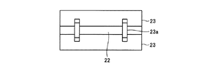
ヨウ素吸着部14は、3つのヨウ素フィルタ20を含んで構成されている。ヨウ素フィルタ20は、チャンバ13内に設けられたガスケット21の内部に並列して設けられている。ヨウ素フィルタ20は、ガス導入孔22を有する一対のガス導入部23と、排ガス11中に含まれる放射性ヨウ素を吸着するヨウ素吸着材24を収容する一対のフィルタ本体25とからなる。フィルタ本体25には複数の孔が設けられ、フィルタ本体25の内側と外側とを気体が通過可能に構成されている。図2は、ヨウ素フィルタ20を排ガス11の流れ方向から見たときの正面図である。図2に示すように、一対のガス導入部23は、一対の連結部23aにより連結されている。また、一対のフィルタ本体25のガス導入部23とは他端側には後板26が設けられている。また、複数のヨウ素フィルタ20を試験することができるように、ヨウ素吸着部14はチャンバ13から着脱可能にする。
The
排ガス11は、原子力施設から排出される排ガスであり、排ガス11はダクト12を介してチャンバ13内に送給され、ガス導入孔22を通過してフィルタ本体25の内部に侵入し、排ガス11中の放射性ヨウ素がヨウ素吸着材24に吸着された後、フィルタ本体25を通過してヨウ素フィルタ20の後流側に抜ける。ヨウ素吸着部14を通過した排ガス11は、排ガス11中の放射性ヨウ素の濃度を被曝評価上問題のない放射能濃度以下を満たした状態で系外に排出される。
The
ヨウ素吸着材24は、放射性ヨウ素の吸着が可能な材料に成型され、ヨウ素フィルタ20内に充填されている。排ガス11は、ヨウ素吸着材24同士の隙間を通ってヨウ素フィルタ20を通過する。ヨウ素吸着材24として用いられる材料は、排ガス11中の放射性ヨウ素を吸着できるものであればよく、例えば、活性炭を担体としたヨウ素添着活性炭やトリエチレンジアミン(TEDA)添着活性炭、活性炭、銀添着活性炭、または天然ゼオライトあるいは合成ゼオライトを担体とした銀ゼオライト、銀モルデナイト等、またはその他の吸着材を担体として銀を添着した銀シリカゲル、銀アルミナ等などが挙げられる。ヨウ素吸着材24の形状は、ペレット、ブリケット、顆粒状、繊維状、ブランケット状あるいはハニカム状としたものなどが挙げられる。
The
本実施形態では、ヨウ素フィルタ20は、チャンバ13内に設けるようにしているが、本実施形態は、これに限定されるものではなく、チャンバ13内に1、2つ又は4つ以上設けるようにしてもよく、チャンバ13の内径やヨウ素フィルタ20の設置面積やガス導入部23の外径の大きさ等に応じてヨウ素フィルタ20を設ける数は適宜変更するようにしてもよい。
In this embodiment, the iodine filter 20 is provided in the
フッ素含有試薬供給部15は、塩素を含まないフッ素含有試薬30を貯留するフッ素含有試薬貯留部31とダクト12内に塩素を含まないフッ素含有試薬30を供給するフッ素含有試薬供給管32とで構成されている。フッ素含有試薬30は、フッ素含有試薬供給部15からフッ素含有試薬供給管32を介してダクト12の内部に試料ガス33に同伴して送給される。試料ガス33としては、例えば空気などが用いられる。フッ素含有試薬30を含む試料ガス33は、フッ素含有試薬供給管32に設けたノズル孔32aからフッ素含有試薬濃度測定部16の上流側に供給される。
The fluorine-containing
フッ素含有試薬30は、F(フッ素)およびC(炭素)を含み、H(水素)とO(酸素)とN(窒素)との少なくとも一つ以上を更に含むと共に、Cl(塩素)を含まない化合物を用いることが好ましい。フッ素含有試薬30としては、例えば、組成式が(C3F7)3−Nで表される化合物、組成式がC4F9OC2H5で表される化合物、組成式がC6F13OCH3で表される化合物、組成式がCF3(CF2)5CH2CH3(C3F13H5)で表される化合物、組成式が(CH2CHFCF2CF2CF2)で表される化合物などが挙げられる。これらの化合物は、沸点が何れも70℃以上であるため、好適に用いられる。例えば、組成式が(C3F7)3−Nで表される化合物の沸点は、128℃程度であり、組成式がC4F9OC2H5で表される化合物の沸点は、76℃程度であり、組成式がC6F13OCH3で表される化合物の沸点は、98℃程度であり、組成式がCF3(CF2)5CH2CH3で表される化合物の沸点は、114.7℃程度であり、組成式が(CH2CHFCF2CF2CF2)で表される化合物の沸点は、82.5℃程度である。このため、上記のように例示した化合物はフッ素含有試薬30として好適に用いることができる。 The fluorine-containing reagent 30 contains F (fluorine) and C (carbon), further contains at least one of H (hydrogen), O (oxygen), and N (nitrogen), and does not contain Cl (chlorine). It is preferable to use a compound. Examples of the fluorine-containing reagent 30 include a compound represented by a composition formula (C 3 F 7 ) 3 —N, a compound represented by a composition formula C 4 F 9 OC 2 H 5 , and a composition formula represented by C 6 F. A compound represented by 13 OCH 3 , a composition represented by CF 3 (CF 2 ) 5 CH 2 CH 3 (C 3 F 13 H 5 ), and a composition represented by (CH 2 CHFCF 2 CF 2 CF 2 ) The compound etc. which are represented by these are mentioned. Since these compounds all have a boiling point of 70 ° C. or higher, they are preferably used. For example, the boiling point of a compound represented by (C 3 F 7 ) 3 —N is about 128 ° C., and the boiling point of a compound represented by C 4 F 9 OC 2 H 5 is 76 The boiling point of the compound whose composition formula is C 6 F 13 OCH 3 is about 98 ° C. and the boiling point of the compound whose composition formula is CF 3 (CF 2 ) 5 CH 2 CH 3. Is about 114.7 ° C., and the boiling point of the compound represented by the composition formula (CH 2 CHFCF 2 CF 2 CF 2 ) is about 82.5 ° C. For this reason, the compounds exemplified above can be suitably used as the fluorine-containing reagent 30.
第1のフッ素含有試薬濃度測定部16と第2のフッ素含有試薬濃度測定部17とはヨウ素吸着部14を挟んでチャンバ13内に設けられている。第1のフッ素含有試薬濃度測定部16は、ヨウ素フィルタ20の上流側に設けられ、チャンバ13の上流側のダクト12内に挿入され、チャンバ13内のガスを採取する第1のガス採取管41と、採取したガスを分析する第1のガスクロマトグラフ42とを有する。第2のフッ素含有試薬濃度測定部17は、ヨウ素フィルタ20の下流側に設けられ、チャンバ13内に挿入され、チャンバ13内のガスを採取する第2のガス採取管43と採取したガスを分析する第2のガスクロマトグラフ44とを有する。
The first fluorine-containing reagent
フッ素含有試薬供給部15は、制御装置45に接続され、制御装置45は、フッ素含有試薬30の噴霧の有無とその噴霧量を調整する。フッ素含有試薬供給部15は、液状のフッ素含有試薬30を加熱するための電気ヒータ等の加熱手段と、試料ガス33の流量を制御する流量制御手段とを有している。制御装置45は、前記加熱手段および前記流量制御手段と連結し、前記加熱手段の出力(加熱電気量)を制御すると共に、試料ガス33の流量を制御している。フッ素含有試薬供給部15は、液状のフッ素含有試薬30を電気ヒータ等で加熱し、試料ガス33の流量を一定とすることにより、試料ガス33中に蒸発させて所定の濃度としている。
The fluorine-containing
本実施形態では、チャンバ13内に排ガス11を採取するための第1のガス採取管41と第2のガス採取管43とを各々1つずつ設けるようにしているが、本実施形態は、これに限定されるものではなく、チャンバ13の内径やヨウ素フィルタ20の設置枚数やガス導入部23の外径の大きさ等に応じて第1のガス採取管41と第2のガス採取管43との何れか一方又は両方を設ける数は、チャンバ13に各々複数設け、適宜変更するようにしてもよい。
In the present embodiment, one each of the first
ヨウ素フィルタ20のリークを試験する際、ヨウ素フィルタ20の上流側からフッ素含有試薬30を含んだ試料ガス33をチャンバ13内に供給する。フッ素含有試薬30を含む試料ガス33の一部は、第1のガス採取管41で採取され、第1のガスクロマトグラフ42に送給され、試料ガス33中のフッ素含有試薬30の濃度が測定される。
When testing the leak of the iodine filter 20, the
試料ガス33はヨウ素フィルタ20を通過した後、ヨウ素フィルタ20の下流側で第2のガス採取管43に空気の一部は採取され、第2のガスクロマトグラフ44に送給され、試料ガス33中に残存するフッ素含有試薬30の濃度が測定される。試料ガス33中のフッ素含有試薬30はヨウ素フィルタ20のヨウ素吸着材24に殆ど吸着されるため、採取した試料ガス33からフッ素含有試薬30はほとんど検出されない。ヨウ素フィルタ20にリークがある場合、フッ素含有試薬30を含んだ試料ガス33はヨウ素吸着材24を通過しないために吸着されず、ヨウ素フィルタ20の下流側に抜ける。このため、ヨウ素フィルタ20の下流側で第2のガス採取管43により採取された試料ガス33の中からフッ素含有試薬30が検出された場合、ヨウ素フィルタ20にリークがあることが確認できる。
After the
本実施形態において、ヨウ素フィルタ20のリークとは、排ガス11がヨウ素吸着材24を通過する際、ヨウ素フィルタ20とガスケット21との間の隙間を通過してしまい、排ガス11中の放射性ヨウ素がヨウ素吸着材24で除去されないことをいう。フッ素含有試薬30は放射性ヨウ素と同様の挙動を示すことから、ヨウ素フィルタ20にリークがあると、試料ガス33の中のフッ素含有試薬30はヨウ素フィルタ20とガスケット21との間の隙間を通過することになる。
In the present embodiment, the leakage of the iodine filter 20 means that when the
フッ素含有試薬30は、大気圧における沸点が70℃以上であることが好ましい。フッ素含有試薬30の大気圧における沸点が70℃未満の場合、試料ガス33中に含有される水分がフッ素含有試薬30よりヨウ素吸着材24に優先して吸着されるため、フッ素含有試薬30はヨウ素吸着材24に吸着され難くなる。この場合、既にヨウ素吸着材24に吸着している水分によってフッ素含有試薬30の破過時間は極端に短くなるため、ヨウ素フィルタ20のリーク試験が困難となるか実施できなくなる。
The fluorine-containing reagent 30 preferably has a boiling point of 70 ° C. or higher at atmospheric pressure. When the boiling point of the fluorine-containing reagent 30 at atmospheric pressure is less than 70 ° C., the moisture contained in the
図3は、相対湿度が60%程度の時の経過時間と破過率との関係を示す図であり、図4は、相対湿度が80%程度の時の経過時間と破過率との関係を示す図である。図3に示すように、試料ガス33中の相対湿度が60%程度の時には、沸点が60℃未満のフッ素含有試薬30を用いても1.5時間程度の間、ヨウ素吸着材24の破過率をほぼ0で維持することができた(図3中、黒丸)。沸点が70℃以上のフッ素含有試薬30を用いても少なくとも5時間はヨウ素吸着材24の破過率をほぼ0で維持することができた(図3中、白丸)。また、従来、放射性ヨウ素のヨウ素フィルタのリーク試験用に用いられたフロンR−112についても沸点が70℃以上のフッ素含有試薬30を用いた場合と同様、少なくとも5時間はヨウ素吸着材24の破過率をほぼ0で維持することができることから(図3中、白丸)、試料ガス33中の相対湿度が60%程度の場合には、沸点が70℃以上のフッ素含有試薬30はヨウ素フィルタ20のリーク試験用に好適に用いることができる。
FIG. 3 is a diagram showing the relationship between the elapsed time when the relative humidity is about 60% and the breakthrough rate, and FIG. 4 is the relationship between the elapsed time when the relative humidity is about 80% and the breakthrough rate. FIG. As shown in FIG. 3, when the relative humidity in the
これに対し、図4に示すように、試料ガス33中の相対湿度が80%程度の場合、沸点が60℃未満のフッ素含有試薬30を用いた場合、ヨウ素吸着材24はほぼ試験開始直後に破過してしまった(図4中、黒丸)。このため、ヨウ素フィルタ20をリークしたフッ素含有試薬30はヨウ素フィルタ20とガスケット21との間の隙間からリークしたものに起因するのかヨウ素吸着材24の破過に起因するのかを区別することは困難であり、ヨウ素フィルタ20とガスケット21との間の隙間からリークしたフッ素含有試薬30の正確な測定値を得ることが困難であった。一方、沸点が70℃以上のフッ素含有試薬30として、沸点が76℃のフッ素含有試薬30や沸点が98℃のフッ素含有試薬30や沸点が114.7℃のフッ素含有試薬30や沸点が128℃のフッ素含有試薬30を用いた場合、試料ガス33中の相対湿度が80%程度であっても試験開始から30分程度はヨウ素吸着材24の破過が起こらなかった(図4中、白丸、二重丸、白三角、黒四角)。フロンR−112についても沸点が76℃、98℃、114.7℃、128℃のフッ素含有試薬30を用いた場合と同様の挙動を示し、試験開始から30分程度はヨウ素吸着材24の破過が起こらなかった(図4中、黒四角)。このため、試料ガス33中の相対湿度が80%程度の場合でも、沸点が70℃以上のフッ素含有試薬30を用いれば、ヨウ素フィルタ20のリーク試験を実施するのに十分な時間、ヨウ素吸着材24が破過することなくヨウ素フィルタ20のリーク率を測定することができる。
On the other hand, as shown in FIG. 4, when the relative humidity in the
ヨウ素フィルタ20のリーク試験でヨウ素フィルタ20に吸着されたフッ素含有試薬30は、大部分がヨウ素フィルタ20に吸着された状態となるが、ヨウ素フィルタ20に吸着されたフッ素含有試薬30は、ヨウ素フィルタのヨウ化メチルの捕集容量を減少させる量よりも大幅に少ない使用量としているためヨウ素フィルタ20の放射性ヨウ素の除去性能に影響を与えることはない。 Most of the fluorine-containing reagent 30 adsorbed on the iodine filter 20 in the leak test of the iodine filter 20 is adsorbed on the iodine filter 20, but the fluorine-containing reagent 30 adsorbed on the iodine filter 20 is Since the amount used is much smaller than the amount that reduces the methyl iodide collection capacity, the iodine filter 20 does not affect the radioactive iodine removal performance.
(ヨウ素フィルタのリーク率の評価方法)
本実施形態に係るヨウ素フィルタのリーク試験装置10を用いて行なわれるヨウ素フィルタ20のリーク率の評価方法について具体的に説明する。フッ素含有試薬30を含む試料ガス33はフッ素含有試薬供給管32のノズル孔32aからチャンバ13内へ噴出され、ヨウ素フィルタ20の上流側にフッ素含有試薬30を数分間導入する。ヨウ素フィルタ20の上流側と下流側とで第1のガス採取管41と第2のガス採取管43とからフッ素含有試薬30を含む試料ガス33を採取する。フッ素含有試薬30は試料ガス33中に水分として含まれており、採取したフッ素含有試薬30を第1のガスクロマトグラフ42と第2のガスクロマトグラフ44とにより測定し、下記式(1)よりヨウ素フィルタ20のリーク率を求める。下記式(1)中、Aは、ヨウ素フィルタ20の下流側におけるフッ素含有試薬30の濃度であり、Bは、ヨウ素フィルタ20の上流側におけるフッ素含有試薬30の濃度であり、Cは、ヨウ素フィルタ20の下流側における第2のガスクロマトグラフ44との検出限界濃度であり、Dは、ヨウ素フィルタ20の上流側における第1のガスクロマトグラフ42の検出限界濃度である。
リーク率(%)=(A−C)/(B−D)×100・・・(1)
(Iodine filter leak rate evaluation method)
A method for evaluating the leak rate of the iodine filter 20 performed using the iodine filter leak test apparatus 10 according to the present embodiment will be specifically described. The
Leak rate (%) = (AC) / (BD) × 100 (1)
ヨウ素フィルタ20の判定基準は、加圧水型軽水炉(Pressurized Water Reactor;PWR)プラントの場合、リーク率が1%以下である。第1のガスクロマトグラフ42と第2のガスクロマトグラフ44とによる試料ガス33中のフッ素含有試薬30の検出限界濃度は約10×10-9(10ppb)である。このとき、例えば、ヨウ素フィルタ20を3つ含むヨウ素吸着部14が1000m3/hの試料ガス33の処理能力を有するとし、ヨウ素フィルタ20の上流側からフッ素含有試薬30を注入し、試料ガス33中のフッ素含有試薬30の濃度を30×10-6(30ppm)とし、ヨウ素フィルタ20の下流側で30×10-9(30ppb)のフッ素含有試薬30の濃度を検出した場合、ヨウ素フィルタ20のリーク率は、上記式(1)より0.07%程度と求められる。被曝評価上問題のない放射能濃度とするためのリーク率の判定基準の一例としては1.0%であり、この判定基準の場合には、上記のリーク試験で得られたリーク率0.07%は、リーク率の判定基準を満足すると判断できる。なお、上述した通り、フッ素含有試薬は放射性ヨウ素と同じリーク挙動を示すことから、フッ素含有試薬を用いたリーク試験の値は、放射性ヨウ素のリーク率として扱うことが可能である。
The criterion for determining the iodine filter 20 is a leak rate of 1% or less in the case of a pressurized water reactor (PWR) plant. The detection limit concentration of the fluorine-containing reagent 30 in the
よって、フッ素含有試薬30は、従来用いられていたフロンR−112と同様、ヨウ素吸着材24に高効率で捕集されることから、フッ素含有試薬30のリーク率は、ガスケット21にヨウ素フィルタ20を設けた際に発生し得るヨウ素フィルタ20とガスケット21との間の隙間などの有無によって大きく変化することになる。このフッ素含有試薬30のリーク率の挙動は、放射性ヨウ素がヨウ素吸着材24やヨウ素フィルタ20とガスケット21との間の隙間を通過する場合の挙動と同様である。よって、フッ素含有試薬30がヨウ素フィルタ20を通過する時の挙動から間接的に放射性ヨウ素がヨウ素フィルタ20を通過した際のヨウ素フィルタ20のリークの有無も試験することができる。
Therefore, the fluorine-containing reagent 30 is collected by the
本実施形態に係るヨウ素フィルタのリーク試験装置10により、ヨウ素フィルタ20のリークがないか、所定の基準値(例えば、1.0%)以下であった場合には、ヨウ素フィルタ20は原子力施設から排出される排ガス11中に含まれる放射性ヨウ素を処理するためにそのまま使用することができる。また、ヨウ素フィルタ20のリークが発見された場合には新たなヨウ素フィルタ20をガスケット21内に再充填を行なうか、ヨウ素フィルタ20とガスケット21との間の隙間を埋めるなどする。この場合、再度、上記と同様に本実施形態に係るヨウ素フィルタのリーク試験装置10でヨウ素フィルタ20のリークの有無を判定する。
When the iodine filter leak test apparatus 10 according to the present embodiment has no iodine filter 20 leak or a predetermined reference value (for example, 1.0%) or less, the iodine filter 20 is removed from the nuclear facility. It can be used as it is to treat radioactive iodine contained in the
このように、本実施形態に係るヨウ素フィルタのリーク試験装置10によれば、破過時間が長く、かつ放射性ヨウ素の捕集容量を減少させることなく放射性ヨウ素のリーク率を精度良く容易に試験することができる。このため、従来のフレオン−112を用いたリーク試験法と同様の試験方法を用いることができ、ヨウ素吸着材24が破過しているかヨウ素フィルタ20のリークかの判別が容易となり、高い精度でヨウ素フィルタ20のリークの試験結果を得ることができる。また、ヨウ化メチルを用いたリーク試験法に比べ、ヨウ素フィルタ20の捕集容量の低下を抑制することができる。また、チャンバ13への装着前のヨウ素フィルタ20だけでなく、チャンバ13へ装着後のヨウ素フィルタ20のリーク試験も簡単に行なうことができる。更に、重水蒸気を用いたリーク試験法と異なり、環境を汚染するおそれも無く容易に取扱うことができる。
As described above, according to the iodine filter leak test apparatus 10 according to this embodiment, the breakthrough time is long, and the leak rate of radioactive iodine can be easily and accurately tested without reducing the collection capacity of radioactive iodine. be able to. For this reason, a test method similar to the leak test method using the conventional Freon-112 can be used, and it becomes easy to determine whether the
なお、本実施形態においては、本実施形態に係るヨウ素フィルタのリーク試験装置10を用いてのヨウ素フィルタ20のリークの試験方法について説明したが、本実施形態は、これに限定されるものではなく、ヨウ素フィルタ20以外の他のフィルタについても同様に適用することができる。 In the present embodiment, the iodine filter 20 leak test method using the iodine filter leak test apparatus 10 according to the present embodiment has been described. However, the present embodiment is not limited to this. The same applies to filters other than the iodine filter 20.
本実施形態に係るヨウ素フィルタのリーク試験装置10においては、チャンバ13内にヨウ素吸着部14を1つ設けるようにしているが、本実施形態はこれに限定されるものではない。例えば、チャンバ13の入口から出口までの距離、ヨウ素吸着部14の設置面積等に応じてヨウ素吸着部14を複数設けるようにしてもよい。
In the iodine filter leak test apparatus 10 according to the present embodiment, one
本実施形態に係るヨウ素フィルタのリーク試験装置10は、ダクト12が一つの場合について説明したが、本発明はこれに限定されるものではない。チャンバ13を備えたダクト12が複数設けられている場合には、複数のダクト12に交互に排ガス11を送給し、原子力設備を稼動させながら各々のチャンバ13内のヨウ素フィルタ20のリーク試験を行うようにしてもよい。各々のダクト12ごとにヨウ素吸着部14を備えたチャンバ13を設け、一方のチャンバ13内のヨウ素フィルタ20のリーク試験を行っている間、一方のダクト12への排ガス11の送給を停止し、他方のダクト12に排ガス11を送給し、一方のチャンバ13内のヨウ素フィルタ20を交換するかヨウ素フィルタ20とガスケット21との間の隙間を塞ぐことができる。これにより、原子力設備を停止させることなく、ヨウ素フィルタ20のリーク試験を行い、排ガス11中の放射性ヨウ素を連続して安定してヨウ素フィルタ20に吸着させ、系外に放射性ヨウ素が漏洩するのを確実に防止することができる。
Although the iodine filter leak test apparatus 10 according to the present embodiment has been described with respect to the case where the number of the
本実施形態に係るヨウ素フィルタのリーク試験装置10においては、ヨウ素フィルタ20をチャンバ13に設けるようにしているが、本発明はこれに限定されるものではなく、ヨウ素フィルタ20をチャンバ13以外のダクト12などに設けるようにしてもよい。
In the iodine filter leak test apparatus 10 according to the present embodiment, the iodine filter 20 is provided in the
本実施形態に係るヨウ素フィルタのリーク試験装置10においては、原子力発電所など原子力施設から排出される放射性ヨウ素を含有する排ガス11を対象として説明したが、本実施形態は、これに限定されるものではなく、再処理工場、放射性同位元素取扱施設など原子力施設以外の工場等から排出される放射性ヨウ素を含有する排ガス等においても同様に適用することができる。
In the iodine filter leak test apparatus 10 according to the present embodiment, the
また、本実施形態に係るヨウ素フィルタのリーク試験装置10においては、放射性ヨウ素を吸着させるヨウ素フィルタ20のリークの有無の試験用として用いる場合について説明したが、本実施形態はこれに限定されるものではなく、放射性ヨウ素以外の成分を吸着するフィルタのリーク試験用についても同様に用いることができる。 Further, in the iodine filter leak test apparatus 10 according to the present embodiment, the case where the iodine filter 20 that adsorbs radioactive iodine is used as a test for the presence or absence of a leak has been described, but the present embodiment is limited to this. Instead, it can be used similarly for a leak test of a filter that adsorbs components other than radioactive iodine.
以上のように、本発明に係るヨウ素フィルタのリーク試験方法及びリーク試験装置は、排ガスに含まれる放射性ヨウ素を除去するヨウ素フィルタのリークの有無の試験を行うことができるので、原子力施設等で発生する排ガス用のフィルタのリーク試験に用いるのに適している。 As described above, the iodine filter leak test method and the leak test apparatus according to the present invention can test whether there is a leak in the iodine filter that removes radioactive iodine contained in the exhaust gas. Suitable for use in leak tests of exhaust gas filters.
10 ヨウ素フィルタのリーク試験装置
11 排ガス(被処理ガス)
12 ダクト
13 チャンバ(容器)
14 ヨウ素吸着部
15 フッ素含有試薬供給部
16 第1のフッ素含有試薬濃度測定部
17 第2のフッ素含有試薬濃度測定部
20 ヨウ素フィルタ
21 ガスケット
22 ガス導入孔
23 ガス導入部
23a 連結部
24 ヨウ素吸着材
25 フィルタ本体
26 後板
30 フッ素含有試薬
31 フッ素含有試薬貯留部
32 フッ素含有試薬供給管
32a ノズル孔
33 試料ガス
41 第1のガス採取管
42 第1のガスクロマトグラフ
43 第2のガス採取管
44 第2のガスクロマトグラフ
45 制御装置
10 Iodine filter
12
DESCRIPTION OF
Claims (7)
前記ヨウ素フィルタより上流側に塩素を含まないフッ素含有試薬を供給し、前記ヨウ素フィルタの上流側および下流側における前記フッ素含有試薬の濃度を測定し、前記ヨウ素フィルタを通過するフッ素含有試薬のリーク率を求めることを特徴とするヨウ素フィルタのリーク試験方法。 Iodine filter leak that detects the leak of an iodine filter that removes radioactive iodine contained in the gas to be treated with an iodine adsorbent in a duct or chamber to which the gas to be treated containing radioactive iodine discharged from a nuclear facility is delivered Test method,
Supplying a fluorine-containing reagent not containing chlorine upstream from the iodine filter, measuring the concentration of the fluorine-containing reagent upstream and downstream of the iodine filter, and the leakage rate of the fluorine-containing reagent passing through the iodine filter A leak test method for an iodine filter, characterized in that:
前記フッ素含有試薬として、フッ素および炭素を含み、水素と酸素と窒素との少なくとも一つ以上を更に含むと共に、塩素を含まない化合物を用いるヨウ素フィルタのリーク試験方法。 In claim 1,
An iodine filter leak test method using a compound containing fluorine and carbon, further containing at least one of hydrogen, oxygen, and nitrogen and not containing chlorine as the fluorine-containing reagent.
前記フッ素含有試薬は、その大気圧下における沸点が70℃以上であるヨウ素フィルタのリーク試験方法。 In claim 1 or 2,
The fluorine-containing reagent is a leak test method for an iodine filter having a boiling point of 70 ° C. or higher under atmospheric pressure.
前記ダクト又はチャンバ内に設けられ、前記ダクト又はチャンバ内に塩素を含まないフッ素含有試薬を供給するフッ素含有試薬供給部と、
前記ヨウ素フィルタの上流側および下流側に設けられ、前記フッ素含有試薬の濃度を測定するフッ素含有試薬濃度測定部と、
を含むことを特徴とするヨウ素フィルタのリーク試験装置。 An iodine filter including an iodine adsorbent that is provided in a duct or a chamber to which a gas to be treated containing radioactive iodine is supplied and adsorbs the radioactive iodine contained in the gas to be treated;
A fluorine-containing reagent supply unit that is provided in the duct or chamber and supplies a fluorine-containing reagent not containing chlorine in the duct or chamber;
A fluorine-containing reagent concentration measuring unit that is provided on the upstream side and the downstream side of the iodine filter and measures the concentration of the fluorine-containing reagent;
A leak test apparatus for iodine filter, comprising:
前記フッ素含有試薬は、フッ素および炭素を含み、水素と酸素と窒素との少なくとも一つ以上を更に含むと共に、塩素を含まない化合物であるヨウ素フィルタのリーク試験装置。 In claim 4,
The fluorine-containing reagent includes a fluorine and carbon, further includes at least one of hydrogen, oxygen, and nitrogen, and further includes a chlorine-free iodine filter leak test apparatus.
前記フッ素含有試薬は、その大気圧下における沸点が70℃以上であるヨウ素フィルタのリーク試験装置。 In claim 4 or 5,
The fluorine-containing reagent is an iodine filter leak test apparatus having a boiling point of 70 ° C. or higher under atmospheric pressure.
前記被処理ガスが、原子力施設から排出される排ガスであるヨウ素フィルタのリーク試験装置。 In any one of Claims 4 thru | or 6,
An iodine filter leak test apparatus in which the gas to be treated is exhaust gas discharged from a nuclear facility.
Priority Applications (4)
| Application Number | Priority Date | Filing Date | Title |
|---|---|---|---|
| JP2010108638A JP5595110B2 (en) | 2010-05-10 | 2010-05-10 | Iodine filter leak test method, leak test apparatus, and fluorine-containing reagent |
| EP11780500.2A EP2571030B1 (en) | 2010-05-10 | 2011-04-25 | Method and device for testing for leaks in iodine filters |
| US13/697,073 US8919184B2 (en) | 2010-05-10 | 2011-04-25 | Leak testing method and leak testing device for iodine filter |
| PCT/JP2011/060080 WO2011142243A1 (en) | 2010-05-10 | 2011-04-25 | Method and device for testing for leak in iodine filter |
Applications Claiming Priority (1)
| Application Number | Priority Date | Filing Date | Title |
|---|---|---|---|
| JP2010108638A JP5595110B2 (en) | 2010-05-10 | 2010-05-10 | Iodine filter leak test method, leak test apparatus, and fluorine-containing reagent |
Publications (3)
| Publication Number | Publication Date |
|---|---|
| JP2011237267A true JP2011237267A (en) | 2011-11-24 |
| JP2011237267A5 JP2011237267A5 (en) | 2013-07-04 |
| JP5595110B2 JP5595110B2 (en) | 2014-09-24 |
Family
ID=44914299
Family Applications (1)
| Application Number | Title | Priority Date | Filing Date |
|---|---|---|---|
| JP2010108638A Expired - Fee Related JP5595110B2 (en) | 2010-05-10 | 2010-05-10 | Iodine filter leak test method, leak test apparatus, and fluorine-containing reagent |
Country Status (4)
| Country | Link |
|---|---|
| US (1) | US8919184B2 (en) |
| EP (1) | EP2571030B1 (en) |
| JP (1) | JP5595110B2 (en) |
| WO (1) | WO2011142243A1 (en) |
Cited By (4)
| Publication number | Priority date | Publication date | Assignee | Title |
|---|---|---|---|---|
| JP2017032437A (en) * | 2015-08-03 | 2017-02-09 | 三菱重工業株式会社 | Storage device and storage method for radioactive iodine adsorbent |
| CN110715975A (en) * | 2019-09-03 | 2020-01-21 | 中国辐射防护研究院 | An online measuring device and method for evaluating the efficiency of an iodine adsorber with non-radioactive methyl iodide |
| CN112051006A (en) * | 2020-09-09 | 2020-12-08 | 广东冠电科技股份有限公司 | Instrument and instrument equipment on-line monitoring device based on industrial internet |
| JP7490551B2 (en) | 2020-12-25 | 2024-05-27 | 大陽日酸株式会社 | Airtightness test method |
Families Citing this family (5)
| Publication number | Priority date | Publication date | Assignee | Title |
|---|---|---|---|---|
| CN103903660B (en) * | 2012-12-26 | 2016-12-28 | 中国辐射防护研究院 | A kind of halogen generator |
| CN104826448A (en) * | 2015-04-15 | 2015-08-12 | 中国核电工程有限公司 | Iodine adsorption apparatus |
| CN110095233A (en) * | 2018-01-31 | 2019-08-06 | 中国辐射防护研究院 | A kind of detection system and detection method of iodine adsorber slip |
| CN110068434B (en) * | 2019-03-29 | 2021-05-18 | 中国辐射防护研究院 | Pulse type cyclohexane gas cold generator for detecting leakage rate of iodine adsorber |
| CN116892387B (en) * | 2023-07-10 | 2024-05-24 | 河南省科学院同位素研究所有限责任公司 | Preparation method of radioactive isotope tracer for oilfield gas flooding monitoring |
Citations (4)
| Publication number | Priority date | Publication date | Assignee | Title |
|---|---|---|---|---|
| JPS5912337A (en) * | 1982-07-12 | 1984-01-23 | Toshiba Corp | Filter testing device |
| JPS59126281A (en) * | 1983-01-07 | 1984-07-20 | Nippon Atom Ind Group Co Ltd | Leakage detection of radioactive iodine removing filter |
| JP2003130992A (en) * | 2001-10-26 | 2003-05-08 | Mitsubishi Heavy Ind Ltd | Iodine filter performance evaluation device and its operation method |
| JP2010040916A (en) * | 2008-08-07 | 2010-02-18 | Agc Seimi Chemical Co Ltd | Flux creep-up preventive composition for solder, electronic member for solder coated with the composition, method of soldering the member, and electronic product |
Family Cites Families (5)
| Publication number | Priority date | Publication date | Assignee | Title |
|---|---|---|---|---|
| JPS58172548A (en) | 1982-04-02 | 1983-10-11 | Nippon Atom Ind Group Co Ltd | Leak detection of radio active iodine removing filter |
| JP3071057B2 (en) | 1993-01-22 | 2000-07-31 | 株式会社日立製作所 | Method and apparatus for detecting leak of adsorbent-filled filter |
| JPH07148418A (en) | 1993-11-30 | 1995-06-13 | Hitachi Ltd | Leak test method for iodine filter and test apparatus therefor |
| US20050211949A1 (en) * | 2003-11-13 | 2005-09-29 | Bivens Donald B | Detectable refrigerant compositions and uses thereof |
| US7752892B2 (en) * | 2006-09-07 | 2010-07-13 | Matheson Tri-Gas | Leak characterization apparatuses and methods for fluid storage containers |
-
2010
- 2010-05-10 JP JP2010108638A patent/JP5595110B2/en not_active Expired - Fee Related
-
2011
- 2011-04-25 WO PCT/JP2011/060080 patent/WO2011142243A1/en not_active Ceased
- 2011-04-25 EP EP11780500.2A patent/EP2571030B1/en active Active
- 2011-04-25 US US13/697,073 patent/US8919184B2/en active Active
Patent Citations (4)
| Publication number | Priority date | Publication date | Assignee | Title |
|---|---|---|---|---|
| JPS5912337A (en) * | 1982-07-12 | 1984-01-23 | Toshiba Corp | Filter testing device |
| JPS59126281A (en) * | 1983-01-07 | 1984-07-20 | Nippon Atom Ind Group Co Ltd | Leakage detection of radioactive iodine removing filter |
| JP2003130992A (en) * | 2001-10-26 | 2003-05-08 | Mitsubishi Heavy Ind Ltd | Iodine filter performance evaluation device and its operation method |
| JP2010040916A (en) * | 2008-08-07 | 2010-02-18 | Agc Seimi Chemical Co Ltd | Flux creep-up preventive composition for solder, electronic member for solder coated with the composition, method of soldering the member, and electronic product |
Cited By (5)
| Publication number | Priority date | Publication date | Assignee | Title |
|---|---|---|---|---|
| JP2017032437A (en) * | 2015-08-03 | 2017-02-09 | 三菱重工業株式会社 | Storage device and storage method for radioactive iodine adsorbent |
| CN110715975A (en) * | 2019-09-03 | 2020-01-21 | 中国辐射防护研究院 | An online measuring device and method for evaluating the efficiency of an iodine adsorber with non-radioactive methyl iodide |
| CN112051006A (en) * | 2020-09-09 | 2020-12-08 | 广东冠电科技股份有限公司 | Instrument and instrument equipment on-line monitoring device based on industrial internet |
| CN112051006B (en) * | 2020-09-09 | 2023-03-10 | 广东冠电科技股份有限公司 | Instrument and instrument equipment on-line monitoring device based on industrial internet |
| JP7490551B2 (en) | 2020-12-25 | 2024-05-27 | 大陽日酸株式会社 | Airtightness test method |
Also Published As
| Publication number | Publication date |
|---|---|
| US20130047707A1 (en) | 2013-02-28 |
| EP2571030A1 (en) | 2013-03-20 |
| WO2011142243A1 (en) | 2011-11-17 |
| US8919184B2 (en) | 2014-12-30 |
| JP5595110B2 (en) | 2014-09-24 |
| EP2571030A4 (en) | 2015-03-18 |
| EP2571030B1 (en) | 2016-12-28 |
Similar Documents
| Publication | Publication Date | Title |
|---|---|---|
| JP5595110B2 (en) | Iodine filter leak test method, leak test apparatus, and fluorine-containing reagent | |
| CN105572298B (en) | Radioactive waste gas treatment unit inert gas retention bed activated carbon performance test system | |
| KR101504753B1 (en) | Mask Filter Test System | |
| Bastani et al. | Assessing the performance of air cleaning devices–A full-scale test method | |
| Zhou et al. | Prediction of radon removal efficiency for a flow-through activated charcoal system and radon mitigation characteristics | |
| CN102608271A (en) | Direct determination method for mercury content in natural gas | |
| JP2013040884A (en) | Radioactive substance removing device | |
| CN105572299B (en) | Radioactive waste gas treatment system dehumidification drying unit desiccant performance test system | |
| US4237726A (en) | Process for predicting the useful life of a respirator cartridge | |
| Obruchikov et al. | Removal of radioactive methyliodide from the gas stream with a composite sorbent based on polyurethane foam | |
| CN110726776A (en) | Equipment and method for testing adsorption efficiency of iodine adsorber of nuclear facility | |
| CN220913061U (en) | A test device for evaluating the performance of methyl iodide absorption liquid | |
| CN110095233A (en) | A kind of detection system and detection method of iodine adsorber slip | |
| JP5827776B2 (en) | Measuring method, nuclear fuel damage detection method using the same, measuring device and method of using the same | |
| KR102258789B1 (en) | Activated carbon fiber adsorbent for removing radioactive gases the method thereof | |
| CN106896397B (en) | Test method and system for radioactive aerosol monitoring technical device | |
| Zhang et al. | Experimental validation of adsorption filter model under dynamic VOC concentrations: Prediction of long-term efficiency | |
| ES2371558T3 (en) | PROCEDURE FOR CONTROLLING THE EXHAUST RATE OF ACTIVE CARBON FILTERS. | |
| CN212379130U (en) | Device for measuring concentration lower than gas detection limit | |
| Zhou et al. | Use of Wheeler–Jonas equation to explain xenon dynamic adsorption breakthrough curve on granular activated carbon | |
| Rastunov et al. | Evaluation of the sorbent layer thickness in iodine filters | |
| Ji | The activation study of activated charcoal for radioactive off-gas treatment systems in NPPs | |
| Yua et al. | Study on leakage test of iodine adsorber using cyclohexane | |
| CN116243372B (en) | A portable real-time radioactive xenon monitor and monitoring method | |
| Altuntas et al. | Long-term study of optimal gas purifiers for the RPC systems at LHC |
Legal Events
| Date | Code | Title | Description |
|---|---|---|---|
| A521 | Request for written amendment filed |
Free format text: JAPANESE INTERMEDIATE CODE: A523 Effective date: 20130509 |
|
| A621 | Written request for application examination |
Free format text: JAPANESE INTERMEDIATE CODE: A621 Effective date: 20130509 |
|
| A131 | Notification of reasons for refusal |
Free format text: JAPANESE INTERMEDIATE CODE: A131 Effective date: 20140430 |
|
| A521 | Request for written amendment filed |
Free format text: JAPANESE INTERMEDIATE CODE: A523 Effective date: 20140620 |
|
| TRDD | Decision of grant or rejection written | ||
| A01 | Written decision to grant a patent or to grant a registration (utility model) |
Free format text: JAPANESE INTERMEDIATE CODE: A01 Effective date: 20140715 |
|
| A61 | First payment of annual fees (during grant procedure) |
Free format text: JAPANESE INTERMEDIATE CODE: A61 Effective date: 20140805 |
|
| R151 | Written notification of patent or utility model registration |
Ref document number: 5595110 Country of ref document: JP Free format text: JAPANESE INTERMEDIATE CODE: R151 |
|
| R250 | Receipt of annual fees |
Free format text: JAPANESE INTERMEDIATE CODE: R250 |
|
| LAPS | Cancellation because of no payment of annual fees |