JP2011237320A - Apparatus for transferring radioactive sludge - Google Patents
Apparatus for transferring radioactive sludge Download PDFInfo
- Publication number
- JP2011237320A JP2011237320A JP2010110096A JP2010110096A JP2011237320A JP 2011237320 A JP2011237320 A JP 2011237320A JP 2010110096 A JP2010110096 A JP 2010110096A JP 2010110096 A JP2010110096 A JP 2010110096A JP 2011237320 A JP2011237320 A JP 2011237320A
- Authority
- JP
- Japan
- Prior art keywords
- sludge
- tank
- supernatant water
- liquid
- transfer
- Prior art date
- Legal status (The legal status is an assumption and is not a legal conclusion. Google has not performed a legal analysis and makes no representation as to the accuracy of the status listed.)
- Granted
Links
Images


Landscapes
- Treatment Of Sludge (AREA)
Abstract
【課題】スラッジ貯蔵タンクに貯蔵された、放射性物質により汚染された放射性スラッジを、タンク点検等のために別のタンクに、安全にしかも確実に移送するための放射性スラッジ移送装置を提供する。
【解決手段】スラッジ1に、タンクT1内の上澄み水2を吹き付けてスラッジ液4を形成する攪拌機3と、スラッジ液4を移送タンクT2に移送するスラッジ液移送手段5と、移送タンクT2において形成された上澄み水2をスラッジ貯蔵タンクT1に貯蔵されたスラッジ1に吹き付けて粉砕するスラッジ粉砕手段6と、攪拌機3、スラッジ液移送手段5およびスラッジ粉砕手段6の作動を遠隔制御する制御手段とを備える。
【選択図】図1Provided is a radioactive sludge transfer device for safely and reliably transferring radioactive sludge stored in a sludge storage tank and contaminated with radioactive substances to another tank for tank inspection or the like.
SOLUTION: A stirrer 3 for spraying supernatant water 2 in a tank T1 onto sludge 1 to form a sludge liquid 4, sludge liquid transfer means 5 for transferring the sludge liquid 4 to a transfer tank T2, and formation in a transfer tank T2. Sludge pulverizing means 6 for blowing and pulverizing the supernatant water 2 applied to the sludge 1 stored in the sludge storage tank T1, and control means for remotely controlling the operations of the agitator 3, the sludge liquid transfer means 5 and the sludge pulverizing means 6. Prepare.
[Selection] Figure 1
Description
この発明は、放射性スラッジ移送装置、特に、スラッジ貯蔵タンクに貯蔵された、放射性物質により汚染された放射性スラッジを、タンク点検等のために別のタンクに、安全にしかも確実に移送するための放射性スラッジ移送装置に関するものである。 The present invention relates to a radioactive sludge transfer device, and more particularly, a radioactive sludge stored in a sludge storage tank and safely transferred to another tank for a tank inspection or the like for safe and reliable transfer of radioactive sludge. The present invention relates to a sludge transfer device.
原子力発電所の運転に伴って発生するイオン交換樹脂やろ過助材等からなる、放射性物質により汚染された放射性スラッジ(以下、単に、スラッジという。)は、放射能減衰のために一定期間、上澄み水と共にスラッジ貯蔵タンクに貯蔵され、この後、このスラッジ貯蔵タンクから抜き出し、処理工程に移送して処理される。 Radioactive sludge contaminated with radioactive materials (hereinafter simply referred to as sludge), which consists of ion exchange resins and filter aids generated during the operation of nuclear power plants, is clarified for a certain period of time due to radioactive attenuation. It is stored together with water in a sludge storage tank, and then extracted from the sludge storage tank and transferred to a processing step for processing.
なお、上澄み水は、次の理由により発生する。スラッジをスラッジ貯蔵タンクに移送する場合、スラッジ単独での移送が不可能なために、水等と混合して、流動性を持ったスラッジ液とする必要がある。このようにして形成されたスラッジ液をスラッジ貯蔵タンクに搬送すると、スラッジが沈降してスラッジ上に上澄み水が発生する。 Supernatant water is generated for the following reasons. When the sludge is transferred to the sludge storage tank, since it is impossible to transfer the sludge alone, it is necessary to mix it with water or the like to obtain a fluidized sludge liquid. When the sludge liquid thus formed is conveyed to a sludge storage tank, the sludge settles and supernatant water is generated on the sludge.
このようなスラッジ貯蔵タンクには、高い信頼性が要求されるために、定期的に点検を行い、必要に応じて補修を行う必要がある。タンクの点検等を行うためには、スラッジ貯蔵タンク内を空にする必要がある。このためには、スラッジ貯蔵タンクに貯蔵されたスラッジを別のタンクに移送する必要があるが、この移送作業は、作業者の放射線による被ばくを最小限に抑えて行うことが不可欠である。 Since such a sludge storage tank is required to have high reliability, it is necessary to periodically inspect and repair the sludge storage tank as necessary. In order to check the tank, it is necessary to empty the sludge storage tank. For this purpose, it is necessary to transfer the sludge stored in the sludge storage tank to another tank, and it is essential to carry out this transfer operation while minimizing the exposure of the worker to radiation.
この問題を解決すべく提案された放射性スラッジ移送装置の一例が特許文献1(特許第4356728号公報)に開示されている。以下、この放射性スラッジ移送装置を従来移送装置といい、図面を参照しながら説明する。 An example of a radioactive sludge transfer device proposed to solve this problem is disclosed in Patent Document 1 (Japanese Patent No. 4356728). Hereinafter, this radioactive sludge transfer device is referred to as a conventional transfer device and will be described with reference to the drawings.
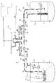
図9は、従来移送装置を示す概略構成図である。 FIG. 9 is a schematic configuration diagram illustrating a conventional transfer device.
図9において、T1は、スラッジ31が貯蔵されたスラッジ貯蔵タンク、T2は、スラッジ貯蔵タンクT1に貯蔵されたスラッジ31が移送される移送タンク、32は、スラッジ31の上澄み水、33は、空気吹き込み装置であり、空気供給源34、空気パイプ35および空気ノズル36からなっている。空気吹き込み装置33は、スラッジ貯蔵タンクT1に貯蔵されたスラッジ31の上澄み水32に空気を吹き込んで、上澄み水32を局部的に攪拌し、これにより流動性を有するスラッジ液37を形成する。
In FIG. 9, T1 is a sludge storage tank in which the
P1は、スラッジ貯蔵タンクT1内のスラッジ移送ポンプ、P2は、移送タンクT2内の上澄み水返還ポンプ、38は、スラッジ移送ポンプP1に接続され、移送タンクT2内に至るスラッジ液移送経路、39は、上澄み水返還ポンプP2に接続された上澄み水移送経路、40は、上澄み水移送経路39に接続された上澄み水噴出装置である。上澄み水噴出装置40は、上澄み水移送経路39からの上澄み水32を、スラッジ貯蔵タンクT1に貯蔵されたスラッジ31に向けて上澄み水パイプ41に取り付けられた上澄み水噴出ノズル42から高圧水ジェットとして吹き付ける。
P1 is a sludge transfer pump in the sludge storage tank T1, P2 is a supernatant water return pump in the transfer tank T2, 38 is a sludge liquid transfer path that is connected to the sludge transfer pump P1 and reaches the transfer tank T2, and 39 A supernatant
上記空気パイプ35、スラッジ液移送経路38、上澄み水移送経路39および上澄み水パイプ41は、何れも、放射線遮蔽手段44により遮蔽された点検孔43からスラッジ貯蔵タンクT1あるいは移送タンクT2に挿入されている。
The
45は、スラッジ貯蔵タンクT1に設置された監視カメラであり、スラッジ貯蔵タンクT1内のスラッジ液37の形成状態等を監視する。46は、移送タンクT2内に設置された監視カメラであり、移送タンクT2内の上澄み水32の形成状態等を監視する。47は、制御装置であり、監視カメラ45、46からの映像情報等に基づいて、空気吹き込み装置33、上澄み水噴出装置40、スラッジ液移送経路38および上澄み水移送経路39に取り付けられたバルブB1からB4等を操作して、スラッジ31の移送の一連の作業を制御する。
45 is a monitoring camera installed in the sludge storage tank T1, and monitors the formation state of the
このように構成されている従来移送装置によれば、以下のようにして、スラッジ貯蔵タンクT1に貯蔵されたスラッジ1が移送タンクT2内に移送される。
According to the conventional transfer apparatus configured as described above, the
先ず、空気吹き込み装置33によって空気をスラッジ貯蔵タンクT1内の上澄み水に吹き込んで上澄み水を局部的に攪拌する。これによって、スラッジ貯蔵タンクT1に貯蔵されたスラッジ31が粉砕され、スラッジ31上に流動性を有するスラッジ液37が形成される。
First, air is blown into the supernatant water in the sludge storage tank T1 by the air blowing
このようにして、スラッジ液37が形成されたら、このスラッジ液37をスラッジ移送ポンプP1により吸引してスラッジ液移送経路38を通して移送タンクT2に移送する。移送タンクT2内のスラッジ液37は、時間の経過に伴ってスラッジ31と上澄み水32とに分離する。
When the
このようにして、移送タンクT2内に上澄み水32が溜まったら、この上澄み水32を上澄み水返還ポンプP2により吸引して上澄み水移送経路39を通して上澄み水噴出装置40に移送する。上澄み水噴出装置40は、上澄み水32を上澄み水パイプ41を通して上澄み水噴出ノズル42からスラッジ貯蔵タンクT1に貯蔵されたスラッジ31に吹き付ける。これによりスラッジ31が粉砕されてスラッジ液37が形成される。
In this way, when the
この後、再度、スラッジ液37をスラッジ移送ポンプP1により吸引してスラッジ液移送経路38を通して移送タンクT2に移送し、そして、移送タンクT2内の上澄み水32をスラッジ貯蔵タンクT1に貯蔵されたスラッジ31に吹き付ける。
Thereafter, the
以上の操作を繰り返し行うことによって、スラッジ貯蔵タンクT1に貯蔵されたスラッジ31を移送タンクT2内に移送することができる。
By repeating the above operation, the
上述のように、従来移送装置によれば、以下のような利点がもたらされる。
(1)スラッジ31の移送の一連の作業は、監視カメラ45、46からの映像情報等に基づいて、制御装置47が遠隔操作により行うので、作業者の放射線による被ばくを最小限に抑えることができる。
(2)高圧水ジェットによりスラッジ31を粉砕する場合には、スラッジ31を確実に粉砕することができる。スラッジ31の最初の粉砕は、空気の吹き付けにより行う。
(3)スラッジ31の粉砕に用いる高圧水として、もともとスラッジ貯蔵タンクT1内に溜まっていた上澄み水32を使用するので、放射性廃棄物の量が増加することはない。外部からの水を用いると、その分だけ、放射性廃棄物の量が増加する。
As described above, the conventional transfer apparatus provides the following advantages.
(1) Since a series of operations for transferring the
(2) When the
(3) Since the
しかしながら、従来移送装置は、以下のような問題があった。
(a)スラッジ31の最初の粉砕は、空気吹き込み装置33によって空気をスラッジ貯蔵タンクT1内の上澄み水に吹き込んで上澄み水を局部的に攪拌することにより行うが、空気の吹き込みでは、スラッジ31を粉砕しにくく、粉砕に時間がかかる。
(b)空気の吹き込みによりスラッジ31を粉砕した後は、上澄み水32をスラッジ31に吹き付けることによりスラッジ31を粉砕するが、上澄み水32の吹き付けのみでは、スラッジ31の粉砕効率が悪く、スラッジ31の移送に時間がかかる。
However, the conventional transfer device has the following problems.
(A) The first pulverization of the
(B) After the
従って、この発明の目的は、作業者の放射線による被ばくを最小限に抑えることができると共に放射性廃棄物の量を増加させずに移送することができることは勿論、最初の段階からスラッジを効率良く、しかも、確実に粉砕することができ、この結果、スラッジの移送を短時間に行うことができるスラッジ移送装置を提供することにある。 Accordingly, the object of the present invention is to minimize the exposure of workers to radiation and to transfer the radioactive waste without increasing the amount of radioactive waste. And it is providing the sludge transfer apparatus which can grind | pulverize reliably and, as a result, can transfer sludge in a short time.
この発明は、上記目的を達成するためになされたものであって、下記を特徴とするものである。 The present invention has been made to achieve the above object, and is characterized by the following.
[1] 一方のタンクに上澄み水と共に貯蔵されたスラッジを、他方のタンクに移送する放射性スラッジ移送装置において、前記一方のタンクに貯蔵されたスラッジに前記一方のタンク内の上澄み水を吹き付けてスラッジ液を形成する攪拌機と、前記一方のタンク内の前記スラッジ液を前記他方のタンクに移送するスラッジ液移送手段と、前記他方のタンクにおいて前記スラッジ液中のスラッジの沈降により形成された上澄み水を前記一方のタンクに貯蔵されたスラッジに吹き付けて前記スラッジを粉砕するスラッジ粉砕手段と、前記攪拌機、前記スラッジ液移送手段および前記スラッジ粉砕手段の作動を遠隔制御する制御手段とを備え、前記スラッジ液移送手段は、前記一方のタンク内のスラッジ液を吸引し、前記他方のタンクに移送するスラッジ液吸引ポンプを備え、前記スラッジ粉砕手段は、前記他方のタンク内の上澄み水を吸引する上澄み水吸引ポンプと、前記上澄み水吸引ポンプにより吸引された上澄み水を前記一方のタンクに貯蔵されたスラッジに吹き付ける上澄み水吹き付けノズルとを備え、前記攪拌機は、前記一方のタンク内の上澄み水中を自在に移動可能であり、前記上澄み水吹き付けノズルは、ノズル位置が自在に調整可能であることに特徴を有するものである。 [1] In a radioactive sludge transfer device that transfers sludge stored in one tank together with supernatant water to the other tank, sludge is sprayed on the sludge stored in the one tank by spraying the supernatant water in the one tank. A stirrer for forming a liquid, a sludge liquid transfer means for transferring the sludge liquid in the one tank to the other tank, and a supernatant water formed by sedimentation of the sludge in the sludge liquid in the other tank. A sludge crushing means for blowing the sludge stored in the one tank and crushing the sludge; and a control means for remotely controlling the operation of the stirrer, the sludge liquid transfer means and the sludge crushing means, and The transfer means sucks the sludge liquid in the one tank and transfers it to the other tank. The sludge crushing means is stored in the one tank with the supernatant water suction pump for sucking the supernatant water in the other tank, and the supernatant water sucked by the supernatant water suction pump. A supernatant water spray nozzle for spraying on the sludge, the stirrer can freely move in the supernatant water in the one tank, and the nozzle position of the supernatant water spray nozzle can be freely adjusted It has characteristics.
[2] 前記[1]の放射性スラッジ移送装置において、前記攪拌機は、前記一方のタンクに貯蔵されたスラッジに空気と前記一方のタンク内の上澄み水とを吹き付けてスラッジ液を形成することに特徴を有するものである。 [2] In the radioactive sludge transfer device according to [1], the stirrer blows air and supernatant water in the one tank to form sludge liquid on the sludge stored in the one tank. It is what has.
[3] 前記[1]または[2]の放射性スラッジ移送装置において、前記攪拌機は、攪拌機本体と、前記攪拌機本体に浮力を付与するフロートと、前記攪拌機本体の浮力を調整するバラストタンクと、前記一方のタンク内の上澄み水を吸引する攪拌機用吸引ポンプと、前記攪拌機用吸引ポンプにより吸引された上澄み水を噴射する噴射ノズルとを備え、前記噴射ノズルの上澄み水噴射角度は、自在に調整可能であることに特徴を有するものである。 [3] In the radioactive sludge transfer device according to [1] or [2], the stirrer includes a stirrer body, a float that imparts buoyancy to the stirrer body, a ballast tank that adjusts the buoyancy of the stirrer body, A suction pump for a stirrer that sucks the supernatant water in one tank and a spray nozzle that sprays the supernatant water sucked by the suction pump for the stirrer, and the supernatant water spray angle of the spray nozzle can be freely adjusted It is characterized by being.
この発明によれば、以下のような効果がもたらされる。
(1)スラッジの粉砕から移送までを全て遠隔操作により行えるので、作業者の放射線による被ばくを最小限に抑えることができる。
(2)上澄み水を循環使用するので、放射性廃棄物の量が増加しない。
(3)攪拌機により最初の段階からスラッジを上澄み水の吹き付けにより粉砕するので、スラッジを短時間に確実に粉砕することができ、この結果、スラッジの移送を短時間に行うことができる。
(4)攪拌機は、スラッジ貯蔵タンク内の上澄み水中を自在に移動可能であるので、スラッジ貯蔵タンクに貯蔵されているどの場所のスラッジでも確実に効率良く粉砕することが可能であり、この結果、スラッジの移送を短時間に行うことができる。
(5)攪拌機の噴射ノズルを調整することによって、スラッジ液をスラッジ液吸引ポンプ側に選択的に流すこともできるので、スラッジ液吸引ポンプの位置を変えることなく、スラッジ液を効率良く吸引することができる。
According to the present invention, the following effects are brought about.
(1) Since everything from sludge crushing to transfer can be performed by remote control, exposure to radiation by workers can be minimized.
(2) Since the supernatant water is recycled, the amount of radioactive waste does not increase.
(3) Since the sludge is pulverized by spraying the supernatant water from the first stage by the stirrer, the sludge can be pulverized reliably in a short time, and as a result, the sludge can be transferred in a short time.
(4) Since the agitator can freely move in the supernatant water in the sludge storage tank, it is possible to reliably and efficiently pulverize the sludge at any location stored in the sludge storage tank. The sludge can be transferred in a short time.
(5) By adjusting the jet nozzle of the stirrer, the sludge liquid can be selectively flowed to the sludge liquid suction pump side, so that the sludge liquid can be efficiently sucked without changing the position of the sludge liquid suction pump. Can do.
この発明の放射性スラッジ移送装置の一実施態様を、図面を参照しながら説明する。 An embodiment of the radioactive sludge transfer device of the present invention will be described with reference to the drawings.
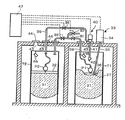
図1は、この発明の放射性スラッジ移送装置によりスラッジ貯蔵タンクT1内のスラッジ液を移送タンクT2に移送している状態を示す概略構成図、図2は、この発明の放射性スラッジ移送装置により移送タンクT2内の上澄み液をスラッジ貯蔵タンクT1内のスラッジに吹き付けてスラッジを粉砕している状態を示す概略構成図である。 FIG. 1 is a schematic configuration diagram showing a state in which the sludge liquid in the sludge storage tank T1 is transferred to the transfer tank T2 by the radioactive sludge transfer device of the present invention, and FIG. 2 is a transfer tank by the radioactive sludge transfer device of the present invention. It is a schematic block diagram which shows the state which sprays the supernatant liquid in T2 on the sludge in sludge storage tank T1, and grind | pulverizes sludge.
図1および図2において、T1は、放射性物質により汚染された放射性スラッジ(以下、単に、スラッジという。)1が貯蔵された、一方のタンクとしての点検対象となるスラッジ貯蔵タンク、T2は、スラッジ貯蔵タンクT1に貯蔵されたスラッジ1が移送される、他方のタンクとしての移送タンク、2は、スラッジ1の上澄み水、3は、攪拌機であり、スラッジ貯蔵タンクT1に貯蔵されたスラッジ1にスラッジ貯蔵タンクT1内の上澄み水2を吹き付けてスラッジ1を粉砕してスラッジ液4を形成する。なお、上澄み水2には、スラッジ1が含まれる場合もあるので、便宜上、スラッジ1を含む上澄み水2も上澄み水2という。
In FIG. 1 and FIG. 2, T1 is a sludge storage tank to be inspected as one tank in which radioactive sludge (hereinafter simply referred to as sludge) 1 contaminated with radioactive material is stored, and T2 is sludge. The
上述したように、スラッジ1は、原子力発電所の運転に伴って発生するイオン交換樹脂やろ過助材等からなり、上澄み液2は、上述した理由により発生し、スラッジ液4は、スラッジ1と上澄み液2とによって形成されるものである。
As described above, the
5は、スラッジ液移送手段であり、スラッジ貯蔵タンクT1内のスラッジ液4を移送タンクT2に移送する。スラッジ液移送手段5は、スラッジ貯蔵タンクT1内のスラッジ液4を吸引し、移送タンクT2に移送するスラッジ液吸引ポンプ7を備えている。スラッジ液吸引ポンプ7により吸引されたスラッジ貯蔵タンクT1内のスラッジ液4は、管路R1、R2、R3を通って移送タンクT2に移送される。管路R1とR2との間には、バルブB1が設けられ、管路R2とR3との間には、バルブB2が設けられている。
5 is a sludge liquid transfer means, which transfers the sludge liquid 4 in the sludge storage tank T1 to the transfer tank T2. The sludge liquid transfer means 5 includes a sludge
6は、スラッジ粉砕手段であり、移送タンクT2においてスラッジ液4中のスラッジ1の沈降により形成された上澄み水2をスラッジ貯蔵タンクT1に貯蔵されたスラッジ1に吹き付けてスラッジ1を粉砕する。スラッジ粉砕手段6は、移送タンクT2内の上澄み水2を吸引する上澄み水吸引ポンプ8と、上澄み水吸引ポンプ8により吸引された上澄み水2をスラッジ貯蔵タンクT1に貯蔵されたスラッジ1に吹き付けて粉砕する上澄み水吹き付けノズル9とを備えている。
6 is a sludge crushing means, and the
上澄み水吹き付けノズル9は、ノズル位置がシリンダー20により自在に調整可能になっている。上澄み水吸引ポンプ8により吸引された上澄み水2は、管路R4、R2、R5を通って上澄み水吹き付けノズル9からスラッジ貯蔵タンクT1に貯蔵されたスラッジ1に吹き付けられる。管路R4とR2との間には、バルブB3が設けられ、管路R2とR5との間には、バルブB4が設けられている。
The nozzle position of the supernatant water spray nozzle 9 can be freely adjusted by the
10は、管路R1、R2、R3、R4、R5内に残留するスラッジ1および上澄み水2を純水により洗浄する洗浄手段である。前記管路の洗浄は、スラッジ貯蔵タンクT1内のスラッジ液4を移送タンクT2に移送した後、および、移送タンクT2内の上澄み水2をスラッジ貯蔵タンクT1のスラッジ1に吹き付けた後に行われる。この理由は、スラッジ1は、勿論、上澄み水2も放射能を帯びているので、洗浄を行わないとスラッジ1の移送作業時以外に放射線による被ばくのおそれがあるからである。
洗浄手段10は、純水タンク11と空気タンク12とを備え、純水タンク11内の純水は、バルブB5、B6を介して管路R2に供給される。空気タンク12内の空気は、B7、B8を介して管路R2に供給される。
The cleaning means 10 includes a
スラッジ貯蔵タンクT1内のスラッジ液4を移送タンクT2に移送した後の管路R2、R3の洗浄は、次のようにして行われる。純水タンク11内の純水をバルブB5を介して管路R2、R3に通し、この後、空気タンク12内の空気をバルブB7を介して管路R2、R3に通すことにより行われる。
The pipes R2 and R3 after the sludge liquid 4 in the sludge storage tank T1 is transferred to the transfer tank T2 are cleaned as follows. The pure water in the
一方、移送タンクT2内の上澄み水2をスラッジ貯蔵タンクT1のスラッジ1に吹き付けた後の管路R2、R5洗浄は、次のようにして行われる。純水タンク11内の純水をバルブB6を介して管路R2、R5に通し、この後、空気タンク12内の空気をバルブB8を介して管路R2、R5に通すことにより行われる。
On the other hand, cleaning of the pipe lines R2 and R5 after the
なお、管路R1、R2、R3、R4、R5の洗浄に際して使用する純水の量は、僅かであり、しかも、純水を通した後、空気により管路の残留水を排除するので、管路の洗浄は、必要最小限の水量で確実に行える。さらに、管路洗浄の確実性を確保するために、管路にサイトグラス22(目視により管路内を確認できるように管路の一部を透明化するもの)と放射線計(図示せず)を設置した管内線量を監視している。 The amount of pure water used for cleaning the pipes R1, R2, R3, R4, and R5 is very small, and after passing pure water, residual water in the pipes is excluded by air. The road can be washed reliably with the minimum amount of water required. Furthermore, in order to ensure the reliability of the pipeline cleaning, a sight glass 22 (a part of the pipeline is made transparent so that the inside of the pipeline can be visually confirmed) and a radiometer (not shown) are provided on the pipeline. The dose in the pipe where the system is installed is monitored.
13は、スラッジ貯蔵タンクT1内の状況を撮影する監視カメラであり、スラッジ貯蔵タンクT1内のスラッジ液4の形成状態や攪拌機3の位置等を監視する。14は、移送タンクT2内の状況を撮影する監視カメラであり、移送タンクT2内の上澄み液2の形成状態等を監視する。
攪拌機3、スラッジ液移送手段5、スラッジ粉砕手段6の作動は、監視カメラ13、14からの映像情報等に基づいて、制御手段(図示せず)により遠隔制御される。
The operations of the
なお、スラッジ貯蔵タンクT1に設けられた、攪拌機3、スラッジ液吸引ポンプ7および上澄み水吹き付けノズル9の挿入用点検孔(図示せず)、および、移送タンクT2に設けられた、管路R3および上澄み水吸引ポンプ8の挿入用点検孔(図示せず)は、何れも、放射線遮蔽手段(図示せず)により遮蔽されている。
In addition, an inspection hole (not shown) for insertion of the
次に、攪拌機3について、さらに説明する。
Next, the
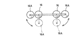
攪拌機3は、図3から図5に示すように、攪拌機本体15と、攪拌機本体15に浮力を付与する複数個(この例では8個)のフロート16と、空気を充填、放出することによって攪拌機本体15の浮力を調整するバラストタンク17と、スラッジ貯蔵タンクT1内の上澄み水2を吸引する攪拌機用吸引ポンプ18と、攪拌機用吸引ポンプ18により吸引された上澄み水2を噴射する複数個(この例では4個)の噴射ノズル19とからなっている。攪拌機用吸引ポンプ18により吸引された上澄み水2は、攪拌機本体15を通って噴射ノズル19に供給される。
As shown in FIGS. 3 to 5, the
噴射ノズル19は、攪拌機本体15の下部コーナー部に下方に向けてそれぞれ1個づつ設けられている。噴射ノズル19は、シリンダー(図示せず)により上澄み水噴射角度が360°の範囲で自在に調整可能になっている。噴射ノズル19の開閉および上澄み水噴射角度の調整は、上記制御手段によって個別に遠隔操作可能になっている。図5に示すように、フロート16の内、外側のフロート16Aは、ヒンジ機構により起倒可能になっていて、下方に倒すことによって、スラッジ貯蔵タンクT1の狭い点検孔からの攪拌機3の搬入を容易にしている。外側のフロート16Aは、スラッジ貯蔵タンクT1内の上澄み水上澄み水2中では、浮力により水平に起き上がって、攪拌機本体15の水平安定性が確保される。
One
バラストタンク17に対する空気の充填、放出は、空気ホース21により行われ、攪拌機用吸引ポンプ18および噴射ノズル19の操作は、上記制御手段により遠隔操作される。
The
攪拌機3は、図6(a)、(b)に示すように、バラストタンク17内の空気を放出することによって、スラッジ貯蔵タンクT1の上澄み水2中を潜水し、図6(c)に示すように、スラッジ貯蔵タンクT1内に貯蔵されたスラッジ1面に到達する。この後、図6(d)に示すように、攪拌機用吸引ポンプ18によってスラッジ貯蔵タンクT1内の上澄み水上澄み水2を吸引し、噴射ノズル19からスラッジ1に向けて噴射させる。これにより、スラッジ1が粉砕されてスラッジ液4が形成される。この際、図8に示すように、噴射ノズル19をスラッジ液吸引ポンプ7の方向に向ければ、スラッジ液4がスラッジ液吸引ポンプ7側に流れるのでスラッジ液4が効果的に吸引される。攪拌機3は、図6(e)、(f)に示すように、バラストタンク17内に空気を充填することによって、浮上し、他の場所に移動可能となる。
As shown in FIGS. 6A and 6B, the
なお、攪拌機3は、図1に示すように、スラッジ1に着底した状態で移動する以外に、上澄み水2の水面とスラッジ1の上面との間の上澄み水2中、あるいは、上澄み水2の水面近傍を移動しながらスラッジ液4を形成することも可能である。
As shown in FIG. 1, the
また、攪拌機3に外部から空気を供給し、スラッジ1に空気とスラッジ貯蔵タンクT1内の上澄み水2とを同時に吹き付ければ、スラッジ液4をより効率良く形成することができる。なお、上述したように、攪拌機3の位置は、監視カメラ13により監視されるが、スラッジ液4は濁っているので、攪拌機3の位置を明確に把握できない場合がある。しかし、スラッジ1に空気と上澄み水2とを同時に吹き付けるようにすれば、空気の吹き付けにより発生する泡により攪拌機3の位置を明確に把握することが可能となる。
Moreover, if air is supplied to the
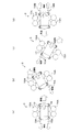
攪拌機3は、図7(a)に示すように、後方の一対の噴射ノズル19Aから上澄み水2を噴射することによって前進し、図7(b)に示すように、後方の一対の噴射ノズル19Aの一方のノズルからのみ上澄み水2を噴射することによって左回転し、後方の一対の噴射ノズル19Aの他方のノズルからのみ上澄み水2を噴射されることによって右回転し、図7(d)に示すように、前方の一対の噴射ノズル19Bから上澄み水2を噴射することによって後退する。
As shown in FIG. 7A, the
このようにして、攪拌機3は、スラッジ貯蔵タンクT1内を自在に移動可能で、しかも、どの位置のスラッジ液4でもスラッジ液吸引ポンプ7側にスラッジ液4を流すことができる。
In this way, the
このように構成されている、この発明の放射性スラッジ移送装置によれば、以下のようにして、スラッジ貯蔵タンクT1に貯蔵されたスラッジ1が移送タンクT2内に移送される。
According to the radioactive sludge transfer device of the present invention configured as described above, the
先ず、図1に示すように、スラッジ貯蔵タンクT1内に攪拌機3を搬入し、上澄み水2中に潜水させる。この後、噴射ノズル19からスラッジ貯蔵タンクT1に貯蔵されたスラッジ1に上澄み水2を噴射し、かくして、スラッジ1を粉砕して、スラッジ液4を形成する。この後、スラッジ液吸引ポンプ7によりスラッジ液4を吸引し、管路R1、R3を経由してスラッジ液4を移送タンクT2に移送する。これによって、所定量のスラッジ1がスラッジ貯蔵タンクT1から移送タンクT2に移送される。この後、洗浄手段10により管路R2、R3を洗浄する。
First, as shown in FIG. 1, the
このようにして、移送タンクT2内にスラッジ液4を移送し、管路R2、R3の洗浄が終了したら、スラッジ液4中のスラッジ1が沈降してスラッジ1と上澄み水2とに分離するまで待機する。スラッジ1と上澄み水2とに分離したら、図2に示すように、移送タンクT2内の上澄み水2を上澄み水吸引ポンプ8により吸引し、管路R4、R2を経由して上澄み水2を上澄み水吹き付けノズル9からスラッジ貯蔵タンクT1に貯蔵されたスラッジ1に吹き付ける。この際、スラッジ貯蔵タンクT1内の上澄み水2の残量は少ないので、上澄み水2の吹き付けによりスラッジ1は確実に粉砕される。なお、上澄み水2の残量が少なくなったスラッジ貯蔵タンクT1内での攪拌機3の使用は行えない。この後、洗浄手段10により管路R5、R2を洗浄する。
In this way, when the sludge liquid 4 is transferred into the transfer tank T2 and the cleaning of the pipes R2 and R3 is completed, the
次に、上澄み水2の吹き付けによりスラッジ貯蔵タンクT1内に上澄み水2が溜まったら、上澄み水2の吹き付けに代えて攪拌機3を作動させて、再度、図1に示すように、スラッジ貯蔵タンクT1内にスラッジ液4を形成する。そして、スラッジ液4を移送タンクT2内に移送する。
Next, when the
以上の操作を繰り返し行うことによって、スラッジ貯蔵タンクT1に貯蔵されたスラッジ1を移送タンクT2内に移送することができる。
By repeating the above operation, the
以上説明したように、この発明によれば、スラッジ1の粉砕から移送までの全ての操作は、上記制御手段による遠隔操作により行えるので、作業者の放射線による被ばくを最小限に抑えることができる。
As described above, according to the present invention, all operations from the pulverization to the transfer of the
また、上澄み水2を循環使用するので、放射性廃棄物の量が増加せず、攪拌機3により最初の段階からスラッジ1を上澄み水2の吹き付けにより粉砕するので、スラッジ1を短時間に確実に粉砕することができ、この結果、スラッジ1の移送を短時間に行うことができる。
In addition, since the
また、攪拌機3は、スラッジ貯蔵タンクT1内の上澄み水2中を自在に移動可能であるので、スラッジ貯蔵タンクT1に貯蔵されているどの場所のスラッジ1でも確実に効率良く粉砕することが可能であり、この結果、スラッジ1の移送を短時間に行うことができる。
Further, since the
さらに、攪拌機3の噴射ノズル19を調整することによって、スラッジ液4をスラッジ液吸引ポンプ7側に選択的に流すことができるので、スラッジ液吸引ポンプ7の位置を変えることなく、スラッジ液4を効率良く吸引することができる。
Further, by adjusting the
1:スラッジ
2:上澄み水
3:攪拌機
4:スラッジ液
5:スラッジ液搬送手段
6:スラッジ粉砕手段
7:スラッジ液吸引ポンプ
8:上澄み水吸引ポンプ
9:上澄み水吹き付けノズル
10:洗浄手段
11:純水タンク
12:空気タンク
13:監視カメラ
14:監視カメラ
15:攪拌機本体
16:フロート
17:バラストタンク
18:攪拌機用吸引ポンプ
19:噴射ノズル
20:シリンダー
21:空気ホース
22:サイトグラス
31:スラッジ
32:上澄み水
33:空気吹き込み装置
34:空気供給源
35:空気パイプ
36:空気ノズル
37:スラッジ液
38:スラッジ液供給経路
39:上澄み水供給経路
40:上澄み水噴出手段
41:上澄み水パイプ
42:上澄み水噴出ノズル
43:点検孔
44:放射線遮断手段
45:監視カメラ
46:監視カメラ
47:制御装置
1: Sludge 2: Supernatant water 3: Stirrer 4: Sludge liquid 5: Sludge liquid conveying means 6: Sludge pulverizing means 7: Sludge liquid suction pump 8: Supernatant water suction pump 9: Supernatant water spray nozzle 10: Washing means 11: Pure Water tank 12: Air tank 13: Surveillance camera 14: Surveillance camera 15: Stirrer body 16: Float 17: Ballast tank 18: Suction pump for agitator 19: Injection nozzle 20: Cylinder 21: Air hose 22: Sight glass 31: Sludge 32 : Supernatant water 33: Air blowing device 34: Air supply source 35: Air pipe 36: Air nozzle 37: Sludge liquid 38: Sludge liquid supply path 39: Supernatant water supply path 40: Supernatant water ejection means 41: Supernatant water pipe 42: Supernatant water ejection nozzle 43: Inspection hole 44: Radiation blocking means 45 Surveillance cameras 46: monitor camera 47: control device
Claims (3)
前記一方のタンクに貯蔵されたスラッジに前記一方のタンク内の上澄み水を吹き付けてスラッジ液を形成する攪拌機と、前記一方のタンク内の前記スラッジ液を前記他方のタンクに移送するスラッジ液移送手段と、前記他方のタンクにおいて前記スラッジ液中のスラッジの沈降により形成された上澄み水を前記一方のタンクに貯蔵されたスラッジに吹き付けて前記スラッジを粉砕するスラッジ粉砕手段と、前記攪拌機、前記スラッジ液移送手段および前記スラッジ粉砕手段の作動を遠隔制御する制御手段とを備え、前記スラッジ液移送手段は、前記一方のタンク内のスラッジ液を吸引し、前記他方のタンクに移送するスラッジ液吸引ポンプを備え、前記スラッジ粉砕手段は、前記他方のタンク内の上澄み水を吸引する上澄み水吸引ポンプと、前記上澄み水吸引ポンプにより吸引された上澄み水を前記一方のタンクに貯蔵されたスラッジに吹き付ける上澄み水吹き付けノズルとを備え、前記攪拌機は、前記一方のタンク内の上澄み水中を自在に移動可能であり、前記上澄み水吹き付けノズルは、ノズル位置が自在に調整可能であることを特徴とする放射性スラッジ移送装置。 In the radioactive sludge transfer device that transfers the sludge stored with the supernatant water in one tank to the other tank,
A stirrer for forming a sludge liquid by spraying the supernatant water in the one tank onto the sludge stored in the one tank, and a sludge liquid transfer means for transferring the sludge liquid in the one tank to the other tank Sludge crushing means for crushing the sludge by spraying the supernatant water formed by sedimentation of sludge in the sludge liquid in the other tank to the sludge stored in the one tank, the stirrer, and the sludge liquid A control means for remotely controlling the operation of the transfer means and the sludge crushing means, and the sludge liquid transfer means includes a sludge liquid suction pump for sucking the sludge liquid in the one tank and transferring it to the other tank. The sludge crushing means comprises a supernatant water suction pump for sucking the supernatant water in the other tank; A supernatant water spray nozzle that sprays the supernatant water sucked by the supernatant water suction pump onto the sludge stored in the one tank, and the agitator is freely movable in the supernatant water in the one tank. The radioactive water sludge transfer device characterized in that the nozzle position of the supernatant water spray nozzle can be freely adjusted.
Priority Applications (1)
| Application Number | Priority Date | Filing Date | Title |
|---|---|---|---|
| JP2010110096A JP5501852B2 (en) | 2010-05-12 | 2010-05-12 | Radioactive sludge transfer device |
Applications Claiming Priority (1)
| Application Number | Priority Date | Filing Date | Title |
|---|---|---|---|
| JP2010110096A JP5501852B2 (en) | 2010-05-12 | 2010-05-12 | Radioactive sludge transfer device |
Publications (2)
| Publication Number | Publication Date |
|---|---|
| JP2011237320A true JP2011237320A (en) | 2011-11-24 |
| JP5501852B2 JP5501852B2 (en) | 2014-05-28 |
Family
ID=45325461
Family Applications (1)
| Application Number | Title | Priority Date | Filing Date |
|---|---|---|---|
| JP2010110096A Active JP5501852B2 (en) | 2010-05-12 | 2010-05-12 | Radioactive sludge transfer device |
Country Status (1)
| Country | Link |
|---|---|
| JP (1) | JP5501852B2 (en) |
Families Citing this family (1)
| Publication number | Priority date | Publication date | Assignee | Title |
|---|---|---|---|---|
| JP5606931B2 (en) * | 2011-01-11 | 2014-10-15 | 太平電業株式会社 | Radioactive sludge transfer device |
Citations (11)
| Publication number | Priority date | Publication date | Assignee | Title |
|---|---|---|---|---|
| JPS52145864A (en) * | 1976-05-29 | 1977-12-05 | Takuo Mochizuki | Submerged stirrer |
| JPS5324569U (en) * | 1976-08-10 | 1978-03-02 | ||
| JPS5486865A (en) * | 1977-12-22 | 1979-07-10 | Toshiba Corp | Liquid sludge stirrer |
| JPS63125186A (en) * | 1986-11-07 | 1988-05-28 | 山本 正幸 | Device for agitating sludge of crude oil tank |
| JPS63194721A (en) * | 1987-02-09 | 1988-08-11 | Nakayama Kankyo Enji Kk | Agitating device for stored water |
| JPH05317610A (en) * | 1992-05-21 | 1993-12-03 | Toyo Eng Corp | Sludge sucking device and system using the same |
| JPH095493A (en) * | 1995-06-21 | 1997-01-10 | Touden Kogyo Kk | Resin suction tool for taking out waste resin |
| JPH09281295A (en) * | 1996-04-16 | 1997-10-31 | Ishikawajima Harima Heavy Ind Co Ltd | Waste sludge agitator |
| JP2002204938A (en) * | 2001-01-12 | 2002-07-23 | Yoshinobu Izawa | Submerged agitator and agitation apparatus |
| JP4356728B2 (en) * | 2006-10-05 | 2009-11-04 | 原電事業株式会社 | Method and apparatus for transporting sludge contaminated with radioactive material |
| JP2010504195A (en) * | 2006-09-21 | 2010-02-12 | ビーエーエスエフ ソシエタス・ヨーロピア | Method for mixing liquid and particulate solids present in a closed container, container for this, ejector jet nozzle, and use of such a nozzle |
-
2010
- 2010-05-12 JP JP2010110096A patent/JP5501852B2/en active Active
Patent Citations (11)
| Publication number | Priority date | Publication date | Assignee | Title |
|---|---|---|---|---|
| JPS52145864A (en) * | 1976-05-29 | 1977-12-05 | Takuo Mochizuki | Submerged stirrer |
| JPS5324569U (en) * | 1976-08-10 | 1978-03-02 | ||
| JPS5486865A (en) * | 1977-12-22 | 1979-07-10 | Toshiba Corp | Liquid sludge stirrer |
| JPS63125186A (en) * | 1986-11-07 | 1988-05-28 | 山本 正幸 | Device for agitating sludge of crude oil tank |
| JPS63194721A (en) * | 1987-02-09 | 1988-08-11 | Nakayama Kankyo Enji Kk | Agitating device for stored water |
| JPH05317610A (en) * | 1992-05-21 | 1993-12-03 | Toyo Eng Corp | Sludge sucking device and system using the same |
| JPH095493A (en) * | 1995-06-21 | 1997-01-10 | Touden Kogyo Kk | Resin suction tool for taking out waste resin |
| JPH09281295A (en) * | 1996-04-16 | 1997-10-31 | Ishikawajima Harima Heavy Ind Co Ltd | Waste sludge agitator |
| JP2002204938A (en) * | 2001-01-12 | 2002-07-23 | Yoshinobu Izawa | Submerged agitator and agitation apparatus |
| JP2010504195A (en) * | 2006-09-21 | 2010-02-12 | ビーエーエスエフ ソシエタス・ヨーロピア | Method for mixing liquid and particulate solids present in a closed container, container for this, ejector jet nozzle, and use of such a nozzle |
| JP4356728B2 (en) * | 2006-10-05 | 2009-11-04 | 原電事業株式会社 | Method and apparatus for transporting sludge contaminated with radioactive material |
Also Published As
| Publication number | Publication date |
|---|---|
| JP5501852B2 (en) | 2014-05-28 |
Similar Documents
| Publication | Publication Date | Title |
|---|---|---|
| JP5606931B2 (en) | Radioactive sludge transfer device | |
| US6924257B2 (en) | Device and method for generating a liquid detergent concentrate from a solid detergent and a method for washing a vehicle | |
| JP2008126145A (en) | Sand collection device for sand basin | |
| JP5501852B2 (en) | Radioactive sludge transfer device | |
| US7311821B2 (en) | Water circulation unit with increased throughput for swimming pools, and filter unit comprising the same | |
| CN103818677B (en) | A kind of buffering blanking control dirt system | |
| KR102405077B1 (en) | Cleaning apparatus for gate of seawater intake installment | |
| JP2010156615A (en) | Method and device for radiation shield | |
| US9580287B2 (en) | Apparatus for preventing beer stone formation and gas-induced foamy beer-spurting phenomenon | |
| WO2012002419A1 (en) | Device for sucking residual radioactive sludge liquid | |
| JP5394337B2 (en) | Residual radioactive sludge liquid suction device | |
| JP4356728B2 (en) | Method and apparatus for transporting sludge contaminated with radioactive material | |
| JP5411812B2 (en) | Residual radioactive sludge liquid suction device | |
| CN105855035A (en) | Sediment automatic cleaning device | |
| KR101557954B1 (en) | Waste removal system of underwater | |
| JP6129116B2 (en) | Drain piping and heat exchanger coil cleaning method for piping | |
| JP6713408B2 (en) | Gas hydrate recovery device and gas hydrate recovery method | |
| CN108408972B (en) | A processing system for domestic sewage | |
| KR102562972B1 (en) | Hybrid blasting system that performs decontamination corresponding to the measured pollution level | |
| KR101733674B1 (en) | Apparatus for preventing the inflow of marine organisom into the intake of power plant useing a air bubble | |
| KR101475760B1 (en) | Cleaning apparatus for intake screen | |
| JPH04315999A (en) | Device for washing waste liquid storage tank for use in nuclear reactor facility | |
| CN207770006U (en) | A kind of service sink based on calcium carbonate grinder | |
| JP3759764B2 (en) | Clinker hopper equipment and its operation method | |
| JPH095493A (en) | Resin suction tool for taking out waste resin |
Legal Events
| Date | Code | Title | Description |
|---|---|---|---|
| A621 | Written request for application examination |
Free format text: JAPANESE INTERMEDIATE CODE: A621 Effective date: 20130405 |
|
| A977 | Report on retrieval |
Free format text: JAPANESE INTERMEDIATE CODE: A971007 Effective date: 20131219 |
|
| A131 | Notification of reasons for refusal |
Free format text: JAPANESE INTERMEDIATE CODE: A131 Effective date: 20131224 |
|
| A521 | Request for written amendment filed |
Free format text: JAPANESE INTERMEDIATE CODE: A523 Effective date: 20140116 |
|
| TRDD | Decision of grant or rejection written | ||
| A01 | Written decision to grant a patent or to grant a registration (utility model) |
Free format text: JAPANESE INTERMEDIATE CODE: A01 Effective date: 20140304 |
|
| A61 | First payment of annual fees (during grant procedure) |
Free format text: JAPANESE INTERMEDIATE CODE: A61 Effective date: 20140312 |
|
| R150 | Certificate of patent or registration of utility model |
Ref document number: 5501852 Country of ref document: JP Free format text: JAPANESE INTERMEDIATE CODE: R150 |
|
| R250 | Receipt of annual fees |
Free format text: JAPANESE INTERMEDIATE CODE: R250 |
|
| R250 | Receipt of annual fees |
Free format text: JAPANESE INTERMEDIATE CODE: R250 |
|
| R250 | Receipt of annual fees |
Free format text: JAPANESE INTERMEDIATE CODE: R250 |
|
| R250 | Receipt of annual fees |
Free format text: JAPANESE INTERMEDIATE CODE: R250 |
|
| R250 | Receipt of annual fees |
Free format text: JAPANESE INTERMEDIATE CODE: R250 |
|
| R250 | Receipt of annual fees |
Free format text: JAPANESE INTERMEDIATE CODE: R250 |
|
| R250 | Receipt of annual fees |
Free format text: JAPANESE INTERMEDIATE CODE: R250 |
|
| R250 | Receipt of annual fees |
Free format text: JAPANESE INTERMEDIATE CODE: R250 |
|
| R250 | Receipt of annual fees |
Free format text: JAPANESE INTERMEDIATE CODE: R250 |
|
| R250 | Receipt of annual fees |
Free format text: JAPANESE INTERMEDIATE CODE: R250 |