JP2011237606A - Window member - Google Patents
Window member Download PDFInfo
- Publication number
- JP2011237606A JP2011237606A JP2010109046A JP2010109046A JP2011237606A JP 2011237606 A JP2011237606 A JP 2011237606A JP 2010109046 A JP2010109046 A JP 2010109046A JP 2010109046 A JP2010109046 A JP 2010109046A JP 2011237606 A JP2011237606 A JP 2011237606A
- Authority
- JP
- Japan
- Prior art keywords
- beam splitter
- window member
- external light
- light
- planar
- Prior art date
- Legal status (The legal status is an assumption and is not a legal conclusion. Google has not performed a legal analysis and makes no representation as to the accuracy of the status listed.)
- Granted
Links
Images


Landscapes
- Securing Of Glass Panes Or The Like (AREA)
- Optical Elements Other Than Lenses (AREA)
- Diffracting Gratings Or Hologram Optical Elements (AREA)
Abstract
【課題】 窓の前方に建物が存在する場合にも、外界景色を観察することができる窓部材を提供する。
【解決手段】 室外側に配置される第一面13bと、第一面13bと前後方向で対向し、室内側に配置される第二面13aとを有する基板形状の窓部材1であって、一部分に形成された入射面11と、入射面11から設定方向となる位置に形成された出射面12とを有し、外界光を窓部材1の板内部に第一面13bから入射させた後、外界光を入射面11で設定方向に反射させて、さらに外界光を第一面13bと第二面13aとで外界光を設定方向へと反射させながら出射面12に導き、外界光を出射面12から室内に導くことを特徴とする。
【選択図】 図1PROBLEM TO BE SOLVED: To provide a window member capable of observing an outside scene even when a building exists in front of a window.
A substrate-shaped window member (1) having a first surface (13b) disposed on the outdoor side and a second surface (13a) opposed to the first surface (13b) in the front-rear direction and disposed on the indoor side, After having the incident surface 11 formed in a part and the output surface 12 formed in the position which becomes a setting direction from the incident surface 11, after allowing external light to enter into the board of the window member 1 from the 1st surface 13b The external light is reflected by the incident surface 11 in the setting direction, and the external light is further guided by the first surface 13b and the second surface 13a to the output surface 12 while reflecting the external light in the setting direction, and the external light is emitted. It is characterized by being guided into the room from the surface 12.
[Selection] Figure 1
Description
本発明は、窓部材に関する。 The present invention relates to a window member.
図5は、従来の窓の平面の概略構成を示す光路図である。なお、Z方向は観察者の前方であり、Y方向は観察者の上方であり、X方向(設定方向)は観察者の左方である。
窓30は、ポリカーボネイト製(屈折率ng)であり、X方向の距離がW2である平板形状であり、室外側に配置される第一面30bと、第一面30bと−Z方向で対向して、室内側に配置される第二面30aとを有する(例えば、特許文献1参照)。
これにより、外界光Lが窓30の板内部に第一面30bから入射した後、基板内部を伝搬して、さらに第二面30aを透過することで室内に到達する。よって、室内にいる観察者P1は、到達した外界光L’を観察することになる。
FIG. 5 is an optical path diagram showing a schematic configuration of a plane of a conventional window. The Z direction is in front of the observer, the Y direction is above the observer, and the X direction (setting direction) is to the left of the observer.
The
Thereby, after the external light L enters the inside of the plate of the
しかしながら、上述したような窓30では、窓30の前方左半分に建物Bが存在する場合には、室内の右半分W1には外界光Lが導かれるが、室内の左半分には外界光Lが導かれなかった。つまり、室内の右半分に位置している観察者P1は外界景色(星印)を観察することができるが、室内の左半分に位置している観察者P2、P3は建物Bや壁31を観察するしかなかった。
However, the
そこで、本件発明者らは、上記課題を解決するために、窓30の前方に建物Bが存在する場合にも、外界景色(星印)を観察することができる窓部材について検討を行った。そこで、窓部材の右側W1に入射面を形成するとともに、入射面の左側に出射面を形成する窓部材を作製した。その結果、窓部材の板内部に第一面から外界光を入射させた後、外界光を入射面で左方向(X方向)に反射させて、さらに外界光を第一面と第二面とで左方向へと反射させながら出射面に導き、外界光を出射面から室内に導くことを見出した。
Therefore, in order to solve the above problems, the present inventors have examined a window member that can observe an external scene (star) even when the building B exists in front of the
すなわち、本発明の窓部材は、室外側に配置される第一面と、当該第一面と前後方向で対向して、室内側に配置される第二面とを有する板形状の窓部材であって、前記前後方向と垂直となる設定方向における窓部材の全体距離に対する窓部材の一部分に形成された入射面と、前記入射面から設定方向となる位置に形成された出射面とを有し、外界光を窓部材の板内部に第一面から入射させた後、前記外界光を入射面で設定方向に反射させて、さらに外界光を第一面と第二面とで外界光を設定方向へと反射させながら出射面に導き、前記外界光を出射面から室内に導くようにしている。 That is, the window member of the present invention is a plate-shaped window member having a first surface disposed on the outdoor side and a second surface disposed on the indoor side facing the first surface in the front-rear direction. An incident surface formed on a part of the window member with respect to the total distance of the window member in a setting direction perpendicular to the front-rear direction, and an emission surface formed at a position that is in the setting direction from the incident surface. After the external light is incident on the inside of the plate of the window member from the first surface, the external light is reflected in the setting direction on the incident surface, and the external light is set on the first surface and the second surface. The light is guided to the exit surface while being reflected in the direction, and the ambient light is guided from the exit surface to the room.
ここで、「設定方向」とは、設計者等によって予め決められた任意の一方向であり、例えば、左方や、右方や、上方や、下方や、左方と右方との二方向や、上方と下方との二方向等となる。
本発明の窓部材によれば、窓の前方に建物等が存在せず、外界景色が存在する位置に、窓部材の入射面を配置する。これにより、本発明の窓部材は、外界光を窓部材の板内部に第一面から入射させる。そして、外界光を入射面で設定方向に反射させる。これにより、第一面と第二面とは、外界光を交互に複数回反射しながら、出射面に導く。そこで、出射面は、外界光を室内に向かって導く。
Here, the “setting direction” is an arbitrary direction predetermined by a designer or the like. For example, the left direction, the right direction, the upper direction, the lower direction, or the left direction and the right direction. Or two directions, such as upward and downward.
According to the window member of the present invention, the entrance surface of the window member is disposed at a position where no building or the like exists in front of the window and an outside scene exists. Thereby, the window member of this invention makes external light inject into the board inside of a window member from a 1st surface. Then, external light is reflected in the setting direction on the incident surface. Thereby, the first surface and the second surface guide the ambient light to the emission surface while alternately reflecting the external light a plurality of times. Therefore, the emission surface guides outside light toward the room.
以上のように、本発明の窓部材によれば、窓の前方に建物が存在する場合にも、外界景色を観察することができる。
また、通行人等が室外から窓部材を通して室内の様子を観察しようとしても、室外の通行人等からは室内の様子が多重表示されたりするため、通行人等が室内の様子を視認することを防止することができる。つまり、ブラインド効果を有するので、カーテンやブラインド等が不要になる。
As described above, according to the window member of the present invention, it is possible to observe an outside scene even when a building exists in front of the window.
In addition, even if a passer-by tries to observe the indoor state through the window member from the outside, since the indoor state is displayed multiple times by the outdoor passer-by, etc., the passer-by can see the indoor state. Can be prevented. That is, since it has a blind effect, a curtain, a blind, etc. become unnecessary.
(他の課題を解決するための手段および効果)
また、本発明の窓部材は、前記出射面は、前記外界光の光束の設定割合を反射するとともに、前記外界光の光束の設定割合を透過することが可能な複数の平面形状のビームスプリッタ面であり、前記ビームスプリッタ面は、お互いに平行であり、かつ、前記第一面及び第二面に対して設定角度で傾斜しているようにしている。
ここで、「設定割合」とは、設計者等によって予め決められた任意の割合であり、例えば、外界光の光束の19%を反射するとともに、外界光の81%を透過するように決められる。
また、「設定角度」とは、設計者等によって予め決められた任意の角度であり、例えば、24°である。
本発明の窓部材によれば、ビームスプリッタ面の数を増やせば増やすほど、外界景色を観察することができる位置の範囲を広げることができる。
さらに、本発明の窓部材は、前記出射面は、前記外界光の光束の設定割合を反射するとともに、前記外界光の光束の設定割合を回折する回折面であるようにしている。
本発明の窓部材によれば、設定方向における回折面が形成される距離を長くすれば長くするほど、外界景色を観察することができる位置の範囲を広げることができる。
(Means and effects for solving other problems)
Further, in the window member of the present invention, the emission surface reflects a set ratio of the light flux of the external light and transmits a set ratio of the light flux of the external light, and has a plurality of planar beam splitter surfaces. The beam splitter surfaces are parallel to each other and are inclined at a set angle with respect to the first surface and the second surface.
Here, the “set ratio” is an arbitrary ratio determined in advance by a designer or the like. For example, the “set ratio” is determined so as to reflect 19% of the light flux of the external light and transmit 81% of the external light. .
The “set angle” is an arbitrary angle determined in advance by a designer or the like, for example, 24 °.
According to the window member of the present invention, as the number of beam splitter surfaces is increased, the range of positions where the external scene can be observed can be expanded.
Furthermore, in the window member of the present invention, the exit surface is a diffractive surface that reflects the set ratio of the light flux of the external light and diffracts the set ratio of the light flux of the external light.
According to the window member of the present invention, the longer the distance at which the diffractive surface is formed in the setting direction, the longer the range of positions where the outside scene can be observed.
以下、本発明の実施形態について図面を用いて説明する。なお、本発明は、以下に説明するような実施形態に限定されるものではなく、本発明の趣旨を逸脱しない範囲で種々の態様が含まれることはいうまでもない。 Hereinafter, embodiments of the present invention will be described with reference to the drawings. Note that the present invention is not limited to the embodiments described below, and it goes without saying that various aspects are included without departing from the spirit of the present invention.
<第一の実施形態>
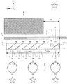
図1は、本発明の一実施形態である窓部材の平面の概略構成を示す光路図である。なお、Z方向は観察者の前方であり、Y方向は観察者の上方であり、X方向(設定方向)は観察者の左方である。また、上述した窓30と同様のものについては、同じ符号を付している。
窓部材1は、ポリカーボネイト製(屈折率ng)であり、X方向の距離がW3である平板形状となり、右側部分(一部分)に形成された平面形状の入射面11と、左側部分に形成された出射面12と、平面形状の第三面14aと、第三面14aとX方向で対向する平面形状の第四面14bと、空気との界面によって第三面14aと第四面14bとの間に形成される側面群13とを有する。
<First embodiment>
FIG. 1 is an optical path diagram showing a schematic plan configuration of a window member according to an embodiment of the present invention. The Z direction is in front of the observer, the Y direction is above the observer, and the X direction (setting direction) is to the left of the observer. Moreover, the same code | symbol is attached | subjected about the thing similar to the
側面群13は、X方向から見ると四角形状となり、平面形状の第一面13bと、第一面13bと−Z方向で対向する平面形状の第二面13aと、平面形状の第五面(図示せず)と、第五面とY方向で対向する平面形状の第六面(図示せず)とを有する。
X方向に対する入射面11の角度は、Y方向から見るとα(例えば、24°)となるように配置されている。そして、入射面11は、外界光Lの光束の81%を反射するとともに、外界光Lの光束の19%を透過することが可能となっている。
The side group 13 has a quadrangular shape when viewed from the X direction, a planar
The angle of the
出射面12は、5枚のビームスプリッタ面からなり、平面形状の第一ビームスプリッタ面12aと、平面形状の第二ビームスプリッタ面12bと、平面形状の第三ビームスプリッタ面12cと、平面形状の第四ビームスプリッタ面12dと、平面形状の第五ビームスプリッタ面12eとを有する。そして、X方向において順番に、第一ビームスプリッタ面12aと、第二ビームスプリッタ面12bと、第三ビームスプリッタ面12cと、第四ビームスプリッタ面12dと、第五ビームスプリッタ面12eとなるように配置されている。さらに、X方向に対する第一ビームスプリッタ面12aの角度と、X方向に対する第二ビームスプリッタ面12bの角度と、X方向に対する第三ビームスプリッタ面12cの角度と、X方向に対する第四ビームスプリッタ面12dの角度と、X方向に対する第五ビームスプリッタ面12eの角度とは、Y方向から見ると同じα(設定角度)となるように配置されている。
The exit surface 12 is composed of five beam splitter surfaces, and includes a planar first
このとき、第一ビームスプリッタ面12aの一端部と第二ビームスプリッタ面12bの一端部と、・・・、第五ビームスプリッタ面12eの一端部とは、第二面13aに接するとともに、第一ビームスプリッタ面12aの他端部と第二ビームスプリッタ面12bの他端部と、・・・、第五ビームスプリッタ面12eの他端部とは、第一面13bに接する。
そして、第一ビームスプリッタ面12aと第二ビームスプリッタ面12bと第三ビームスプリッタ面12cと第四ビームスプリッタ面12dと第五ビームスプリッタ面12eとは、外界光Lの光束の19%を反射するとともに、外界光Lの光束の81%を透過することが可能となっている。
At this time, one end of the first
The first
このような窓部材1を、第一面13bを室外側に配置するとともに、第二面13aを室内側に配置する。このとき、入射面11の前方に建物Bが存在しないように配置する。
その結果、このような窓部材1において、まず、外界光Lが窓部材1の板内部に第一面13bから入射する。そして、外界光Lは入射面11に導かれる。そこで、入射面11は、外界光Lの光束の81%を反射するとともに、外界光Lの光束の19%を透過する。つまり、外界光Lの光束の19.0%である外界光L’の光束を観察者P1に向かって導く。
一方、81%の外界光Lは入射面11で略X方向(設定方向)へと反射する。そして、外界光Lは第一面13bと第二面13aとで交互に複数回反射しながら、第一ビームスプリッタ面12aに導かれる。そこで、第一ビームスプリッタ面12aは、外界光Lの光束の19%を反射するとともに、外界光Lの光束の81%を透過する。つまり、外界光Lの光束の15.4%である外界光Laの光束を室内に向かって導く。
In such a
As a result, in such a
On the other hand, 81% of the external light L is reflected by the
また、第一ビームスプリッタ面12aを透過した外界光Lは、第二ビームスプリッタ面12bに到達する。そこで、第二ビームスプリッタ面12bは、外界光Lの光束の19%を反射するとともに、外界光Lの光束の81%を透過する。つまり、外界光Lの光束の12.5%である外界光Lbの光束を観察者P2に向かって導く。
さらに、第二ビームスプリッタ面12bを透過した外界光Lは、第三ビームスプリッタ面12cや第四ビームスプリッタ面12dや第五ビームスプリッタ面12eに到達していき、各ビームスプリッタ面12c〜12eは、外界光Lの光束の19%を反射するとともに、外界光Lの光束の81%を透過していく。
Further, the external light L transmitted through the first
Further, the external light L transmitted through the second
また、このような窓部材1において、窓部材1の板内部に第二面13aから入射した室内光は、第一ビームスプリッタ面12aや第二ビームスプリッタ面12bや・・・第五ビームスプリッタ面12eに導かれる。そこで、第一ビームスプリッタ面12aや第二ビームスプリッタ面12bや・・・第五ビームスプリッタ面12eは、室内光の光束の19%を反射するとともに、室内光の光束の81%を透過する。つまり、第一ビームスプリッタ面12aや第二ビームスプリッタ面12bや・・・第五ビームスプリッタ面12eは、室内光の光束の一部を入射面11に向かって反射することになる。
入射面11は、室内光の光束の81%を反射するとともに、室内光の光束の19%を透過する。つまり、入射面11は、室内光の光束を通行人(星印位置)等に向かって導くことになる。よって、通行人等は室外から窓部材1を通して室内の様子を観察しようとしても、通行人等からは室内の様子が、第一ビームスプリッタ面12aや第二ビームスプリッタ面12bや・・・第五ビームスプリッタ面12eで反射されたものが重なるように視認される。
Moreover, in such a
The
以上のように、窓部材1によれば、窓30の前方右半分に建物Bが存在する場合にも、室内のどこにいても外界景色(星印)を観察することができる。
また、通行人等が室外から窓部材1を通して室内の様子を観察しようとしても、室外の通行人等からは室内の様子が多重表示されたりするため、通行人等が室内の様子を視認することを防止することができる。
As described above, according to the
In addition, even if a passerby tries to observe the indoor state through the
<第二の実施形態>
上述した窓部材1では、窓部材1を用いる構成を示したが、窓部材1の代わりに下述する窓部材50を用いるような構成としてもよい。図2は、窓部材1の代わりに用いる窓部材50の平面の概略構成を示す図である。
窓部材50は、ポリカーボネイト製(屈折率ng)の平板形状となり、右側部分に形成された平面形状の入射面51と、左側部分に形成された出射面52と、平面形状の第三面54aと、第三面54aとX方向で対向する平面形状の第四面54bと、空気との界面によって第三面54aと第四面54bとの間に形成される側面群53とを有する。
<Second Embodiment>
In the
The
側面群53は、X方向から見ると四角形状となり、平面形状の第一面53bと、第一面53bと−Z方向で対向する平面形状の第二面53aと、平面形状の第五面(図示せず)と、第五面とY方向で対向する平面形状の第六面(図示せず)とを有する。
入射面51は、平面形状の回折面からなり、第二面53a上に形成されている。そして、入射面51は、外界光Lの全光束を略X方向(設定方向)に回折することが可能となっている。
The side group 53 has a quadrangular shape when viewed from the X direction, a planar
The
出射面52は、平面形状の回折面からなり、第一面53b上に所定の面積(X方向での長さは、外界光Lをi回反射させるために必要な長さである)で形成されている。そして、出射面52は、外界光Lの81%を反射するとともに、外界光Lの19%を観察者に回折させて導くことが可能となっている。
The
<第三の実施形態>
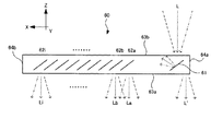
上述した窓部材1では、窓部材1を用いる構成を示したが、窓部材1の代わりに下述する窓部材60を用いるような構成としてもよい。図3は、窓部材1の代わりに用いる窓部材60の平面の概略構成を示す図である。
窓部材60は、ポリカーボネイト製(屈折率ng)の平板形状となり、右側部分に形成された平面形状の入射面61と、左側部分に形成された出射面62と、平面形状の第三面64aと、第三面64aとX方向で対向する平面形状の第四面64bと、空気との界面によって第三面64aと第四面64bとの間に形成される側面群63とを有する。
<Third embodiment>
In the
The
側面群63は、X方向から見ると四角形状となり、平面形状の第一面63bと、第一面63bと−Z方向で対向する平面形状の第二面63aと、平面形状の第五面(図示せず)と、第五面とY方向で対向する平面形状の第六面(図示せず)とを有する。
X方向に対する入射面61の角度は、Y方向から見るとα(例えば、24°)となるように配置されている。そして、入射面61は、外界光Lの光束の100%を反射することが可能となっている。
The side group 63 has a quadrangular shape when viewed from the X direction, a planar
The angle of the
出射面62は、i枚のビームスプリッタ面からなり、平面形状の第一ビームスプリッタ面62aと、平面形状の第二ビームスプリッタ面62bと、・・・、平面形状の第iビームスプリッタ面62iとを有する。そして、X方向において順番に、第一ビームスプリッタ面62aと、第二ビームスプリッタ面62bと、・・・、第iビームスプリッタ面62iとなるように配置されている。さらに、X方向に対する第一ビームスプリッタ面62aの角度と、X方向に対する第二ビームスプリッタ面62bの角度と、・・・、X方向に対する第iビームスプリッタ面62iの角度とは、Y方向から見ると同じαとなるように配置されている。
The exit surface 62 includes i beam splitter surfaces, and includes a planar first
このとき、第一ビームスプリッタ面62aの一端部と第二ビームスプリッタ面62bの一端部と、・・・、第iビームスプリッタ面62iの一端部とは、第二面63aに接しないとともに、第一ビームスプリッタ面62aの他端部と第二ビームスプリッタ面62bの他端部と、・・・、第iビームスプリッタ面62iの他端部とは、第一面63bに接しない。
そして、第一ビームスプリッタ面62aと、第二ビームスプリッタ面62bと、・・・、第iビームスプリッタ面62iとは、外界光Lの光束の100%を反射することが可能となっている。
At this time, one end of the first
The first
<第四の実施形態>
上述した窓部材1では、窓部材1を用いる構成を示したが、窓部材1の代わりに下述する窓部材70を用いるような構成としてもよい。図4は、窓部材1の代わりに用いる窓部材70の平面の概略構成を示す図である。
窓部材70は、ポリカーボネイト製(屈折率ng)の平板形状となり、中央左部分(一部分)に形成された平面形状の第一入射面71と、左側部分に形成された第一出射面72と、中央右部分(一部分)に形成された平面形状の第二入射面81と、右側部分に形成された第二出射面82と、平面形状の第三面74aと、第三面74aとX方向で対向する平面形状の第四面74bと、空気との界面によって第三面74aと第四面74bとの間に形成される側面群73とを有する。
<Fourth embodiment>
In the
The
側面群73は、X方向から見ると四角形状となり、平面形状の第一面73bと、第一面73bと−Z方向で対向する平面形状の第二面73aと、平面形状の第五面(図示せず)と、第五面とY方向で対向する平面形状の第六面(図示せず)とを有する。
The side group 73 has a quadrangular shape when viewed from the X direction, a planar
X方向に対する第一入射面71の角度は、Y方向から見るとα(例えば、24°)となるように配置されている。そして、第一入射面71は、外界光Lの光束の81%を反射するとともに、外界光Lの光束の19%を透過することが可能となっている。
第一出射面72は、3枚のビームスプリッタ面からなり、平面形状の第一ビームスプリッタ面72aと、平面形状の第二ビームスプリッタ面72bと、平面形状の第三ビームスプリッタ面72cとを有する。そして、X方向において順番に、第一ビームスプリッタ面72aと、第二ビームスプリッタ面72bと、第三ビームスプリッタ面72cとなるように配置されている。さらに、X方向に対する第一ビームスプリッタ面72aの角度と、X方向に対する第二ビームスプリッタ面72bの角度と、X方向に対する第三ビームスプリッタ面72cの角度とは、Y方向から見ると同じαとなるように配置されている。
The angle of the
The first emission surface 72 includes three beam splitter surfaces, and includes a planar first beam splitter surface 72a, a planar second
このとき、第一ビームスプリッタ面72aの一端部と第二ビームスプリッタ面72bの一端部と、第三ビームスプリッタ面72cの一端部とは、第二面73aに接するとともに、第一ビームスプリッタ面72aの他端部と第二ビームスプリッタ面72bの他端部と、第三ビームスプリッタ面72cの他端部とは、第一面73bに接する。
そして、第一ビームスプリッタ面72aと第二ビームスプリッタ面72bと第三ビームスプリッタ面72cとは、外界光Lの光束の19%を反射するとともに、外界光Lの光束の81%を透過することが可能となっている。
At this time, one end of the first beam splitter surface 72a, one end of the second
The first beam splitter surface 72a, the second
X方向に対する第二入射面81の角度は、Y方向から見るとβ(例えば、−24°)となるように配置されている。そして、第二入射面81は、外界光Lの光束の81%を反射するとともに、外界光Lの光束の19%を透過することが可能となっている。
第二出射面82は、1枚のビームスプリッタ面82からなる。さらに、−X方向に対するビームスプリッタ面82の角度は、Y方向から見るとβとなるように配置されている。
The angle of the
The
このとき、ビームスプリッタ面82の一端部は、第二面73aに接するとともに、ビームスプリッタ面82の他端部は、第一面73bに接する。
そして、ビームスプリッタ面82は、外界光Lの光束の19%を反射するとともに、外界光Lの光束の81%を透過することが可能となっている。
At this time, one end of the
The
<他の実施形態>
上述した窓部材1において、X方向と設定方向とは一致するような構成を示したが、X方向と設定方向とは一致しないような構成としてもよく、設定方向は任意の一方向とすることができる。
上記窓部材を形成する材料としては、例えば、ポリカーボネイト、ポリメタクリル酸(PMMA)、シクロオレフィン、硝材等が挙げられる。
<Other embodiments>
In the
Examples of the material for forming the window member include polycarbonate, polymethacrylic acid (PMMA), cycloolefin, and glass material.
上述した窓部材1において、各ビームスプリッタ面12a〜12eが、外界光Lの光束の19%を反射するとともに、外界光Lの光束の81%を透過するビームスプリッタ面であるような構成を示したが、各ビームスプリッタ面が、それぞれ異なる割合を反射するとともに、それぞれ異なる割合を透過するビームスプリッタ面であるような構成としてもよい。
In the
本発明は、窓部材等に利用することができる。 The present invention can be used for window members and the like.
1 窓部材
11 入射面
12 出射面
13a 第二面
13b 第一面
L 外界光
DESCRIPTION OF
Claims (3)
前記前後方向と垂直となる設定方向における窓部材の全体距離に対する窓部材の一部分に形成された入射面と、
前記入射面から設定方向となる位置に形成された出射面とを有し、
外界光を窓部材の板内部に第一面から入射させた後、前記外界光を入射面で設定方向に反射させて、さらに外界光を第一面と第二面とで外界光を設定方向へと反射させながら出射面に導き、前記外界光を出射面から室内に導くことを特徴とする窓部材。 A plate-shaped window member having a first surface disposed on the outdoor side, and a second surface disposed on the indoor side facing the first surface in the front-rear direction,
An incident surface formed on a part of the window member with respect to the entire distance of the window member in a setting direction perpendicular to the front-rear direction;
And an exit surface formed at a position that is a setting direction from the entrance surface,
After external light is incident on the inside of the plate of the window member from the first surface, the external light is reflected in the setting direction on the incident surface, and the external light is further set on the first surface and the second surface in the setting direction. A window member, wherein the window member is guided to the exit surface while being reflected to guide the outside light to the room from the exit surface.
前記ビームスプリッタ面は、お互いに平行であり、かつ、前記第一面及び第二面に対して設定角度で傾斜していることを特徴とする請求項1に記載の窓部材。 The exit surface is a plurality of planar beam splitter surfaces capable of reflecting a set ratio of the light flux of the external light and transmitting the set ratio of the light flux of the external light,
The window member according to claim 1, wherein the beam splitter surfaces are parallel to each other and are inclined at a set angle with respect to the first surface and the second surface.
Priority Applications (1)
| Application Number | Priority Date | Filing Date | Title |
|---|---|---|---|
| JP2010109046A JP5447166B2 (en) | 2010-05-11 | 2010-05-11 | Window member |
Applications Claiming Priority (1)
| Application Number | Priority Date | Filing Date | Title |
|---|---|---|---|
| JP2010109046A JP5447166B2 (en) | 2010-05-11 | 2010-05-11 | Window member |
Publications (2)
| Publication Number | Publication Date |
|---|---|
| JP2011237606A true JP2011237606A (en) | 2011-11-24 |
| JP5447166B2 JP5447166B2 (en) | 2014-03-19 |
Family
ID=45325651
Family Applications (1)
| Application Number | Title | Priority Date | Filing Date |
|---|---|---|---|
| JP2010109046A Active JP5447166B2 (en) | 2010-05-11 | 2010-05-11 | Window member |
Country Status (1)
| Country | Link |
|---|---|
| JP (1) | JP5447166B2 (en) |
Citations (5)
| Publication number | Priority date | Publication date | Assignee | Title |
|---|---|---|---|---|
| JPS5144938U (en) * | 1974-10-01 | 1976-04-02 | ||
| JPS616802U (en) * | 1984-06-18 | 1986-01-16 | 鹿島建設株式会社 | window glass |
| JPH1012019A (en) * | 1996-06-24 | 1998-01-16 | Shimizu Corp | Solar lighting system |
| JP2007183317A (en) * | 2006-01-04 | 2007-07-19 | Fuji Electric Holdings Co Ltd | Daylighting equipment |
| JP2009266794A (en) * | 2007-11-29 | 2009-11-12 | Ishikawa Kogaku Zokei Kenkyusho:Kk | Solar light luminaire |
-
2010
- 2010-05-11 JP JP2010109046A patent/JP5447166B2/en active Active
Patent Citations (5)
| Publication number | Priority date | Publication date | Assignee | Title |
|---|---|---|---|---|
| JPS5144938U (en) * | 1974-10-01 | 1976-04-02 | ||
| JPS616802U (en) * | 1984-06-18 | 1986-01-16 | 鹿島建設株式会社 | window glass |
| JPH1012019A (en) * | 1996-06-24 | 1998-01-16 | Shimizu Corp | Solar lighting system |
| JP2007183317A (en) * | 2006-01-04 | 2007-07-19 | Fuji Electric Holdings Co Ltd | Daylighting equipment |
| JP2009266794A (en) * | 2007-11-29 | 2009-11-12 | Ishikawa Kogaku Zokei Kenkyusho:Kk | Solar light luminaire |
Also Published As
| Publication number | Publication date |
|---|---|
| JP5447166B2 (en) | 2014-03-19 |
Similar Documents
| Publication | Publication Date | Title |
|---|---|---|
| CN109656026B (en) | A holographic optical waveguide display device and method with a large field of view | |
| JP6230973B2 (en) | OPTICAL ELEMENT AND EXPANSION OPTICAL ELEMENT HAVING OPTICAL ELEMENT AND LAMPHOUSE | |
| JP5547691B2 (en) | Lighting structure | |
| JP2006075362A (en) | Display device | |
| JP5801065B2 (en) | Liquid crystal display | |
| JP6164648B2 (en) | Optical collimator and lighting unit having such an optical collimator | |
| JP5788145B2 (en) | Lighting device and electronic device | |
| JP2014146551A (en) | Lighting module | |
| WO2013153837A1 (en) | Light guide, light-emitting device, structural body for construction material, door illumination system, and door | |
| KR20170026767A (en) | Display device | |
| CN105629541B (en) | Double-side display device | |
| JP2008164963A (en) | Optical apparatus and display apparatus | |
| JP5059051B2 (en) | Parallax image display device | |
| JP5447166B2 (en) | Window member | |
| CN102621620A (en) | Window set and light guide film thereof | |
| JP2011095576A (en) | Image display device and method of manufacturing the same | |
| JP2010153326A (en) | Multiple-optical-axis photoelectric sensor | |
| JP2014038307A (en) | Light deflection film | |
| TW201422988A (en) | Light guiding system and ceiling structure | |
| JP2007299572A5 (en) | ||
| TW201327320A (en) | Optical touch device and light source assembly | |
| CN210323452U (en) | Light source module and light guide plate | |
| JP2011215320A (en) | Display device | |
| JP2014107167A (en) | Lighting module, door lighting device and window lighting device | |
| US7186011B2 (en) | Multiple point decorative light strip |
Legal Events
| Date | Code | Title | Description |
|---|---|---|---|
| A621 | Written request for application examination |
Free format text: JAPANESE INTERMEDIATE CODE: A621 Effective date: 20120808 |
|
| A977 | Report on retrieval |
Free format text: JAPANESE INTERMEDIATE CODE: A971007 Effective date: 20130724 |
|
| A131 | Notification of reasons for refusal |
Free format text: JAPANESE INTERMEDIATE CODE: A131 Effective date: 20130806 |
|
| A521 | Written amendment |
Free format text: JAPANESE INTERMEDIATE CODE: A523 Effective date: 20130910 |
|
| TRDD | Decision of grant or rejection written | ||
| A01 | Written decision to grant a patent or to grant a registration (utility model) |
Free format text: JAPANESE INTERMEDIATE CODE: A01 Effective date: 20131203 |
|
| A61 | First payment of annual fees (during grant procedure) |
Free format text: JAPANESE INTERMEDIATE CODE: A61 Effective date: 20131216 |
|
| R151 | Written notification of patent or utility model registration |
Ref document number: 5447166 Country of ref document: JP Free format text: JAPANESE INTERMEDIATE CODE: R151 |