JP2011237657A - Tag attaching member - Google Patents
Tag attaching member Download PDFInfo
- Publication number
- JP2011237657A JP2011237657A JP2010109930A JP2010109930A JP2011237657A JP 2011237657 A JP2011237657 A JP 2011237657A JP 2010109930 A JP2010109930 A JP 2010109930A JP 2010109930 A JP2010109930 A JP 2010109930A JP 2011237657 A JP2011237657 A JP 2011237657A
- Authority
- JP
- Japan
- Prior art keywords
- tag
- mounting member
- tag mounting
- loop
- receiving portion
- Prior art date
- Legal status (The legal status is an assumption and is not a legal conclusion. Google has not performed a legal analysis and makes no representation as to the accuracy of the status listed.)
- Granted
Links
Images












Landscapes
- Package Frames And Binding Bands (AREA)
Abstract
【課題】タグ装着部材の挿し込み部への逆挿しを防止することが可能なタグ装着部材を提供する。
【解決手段】タグ装着部材は、ループ成形材1を有し、そのループ成形材の一端に、挿し込み部2となる他端を挿通し、係合する受部3を一体に備えたタグ装着部材であって、前記受部の外面にタグ16の取り付け部12を、その受部の挿通孔の軸芯方向と交差する位置に備えるとともに、前記挿し込み部の先端はスリット6を入れ、複数に割成形して拡開復元可能とした。
【選択図】図2A tag mounting member capable of preventing reverse insertion of a tag mounting member into an insertion portion is provided.
A tag mounting member has a loop molding material 1, and a tag mounting device integrally including a receiving portion 3 through which the other end to be an insertion portion 2 is inserted and engaged with one end of the loop molding material. The member is provided with a mounting portion 12 of the tag 16 on the outer surface of the receiving portion at a position intersecting the axial direction of the insertion hole of the receiving portion, and a slit 6 is provided at the tip of the inserting portion, It is possible to expand and restore by splitting.
[Selection] Figure 2
Description
本発明はタグ装着部材に関し、特に魚介類、野菜、果物等の生鮮食品に対し、ブランドタグを装着するためのタグ装着部材に関する。 The present invention relates to a tag mounting member, and more particularly to a tag mounting member for mounting a brand tag on fresh food such as seafood, vegetables and fruits.
近時、特定域で捕れた魚介類や育成された野菜、果物等に、その特定域であることを表示するブランドタグを装着することが行われている。しかし、この場合、装着対象が生物となるので、その対象の括れた部分を利用して、ループを成形する紐状、帯状等の材料を結束するように、一部を係合ロックして取り付けることが必要となる。 Recently, a seafood caught in a specific area, a grown vegetable, a fruit, or the like is attached with a brand tag indicating that the specific area. However, in this case, since the wearing target is a living thing, a part is engaged and locked so as to bind a string-like or band-like material for forming a loop using the constricted portion of the target. It will be necessary.
そして、前記したブランドタグはそのループを成形する材料の一部に離脱することがないよう、固着しなければならない。また、対象物の装着部位の大きさに応じてループ径も調整することが要求される。このループ径の調整はループを順次絞るように形成することで対応することができる。 The brand tag described above must be fixed so as not to be detached from a part of the material forming the loop. Further, it is required to adjust the loop diameter according to the size of the mounting part of the object. This adjustment of the loop diameter can be dealt with by forming the loops so as to be narrowed down sequentially.
また、前記したループを成形する材料は、紐状、帯状とした一端を挿し込み部が一体に形成され、他端にその挿し込み部が挿し込まれ、抜け止めロックする係止部を備えた受部が形成されている構成が一般的であるが、通常の場合、挿し込み部を受部に対し、逆方向から誤挿入しても、挿入がなされてしまい、引き戻すことはできず、そのループを成形する材料は使用不可とされてしまう。 In addition, the material for forming the loop is provided with an engaging portion that is integrally formed with an insertion portion integrally formed at one end in a string shape or a belt shape, and the insertion portion is inserted at the other end to prevent the removal. The structure in which the receiving part is formed is common, but in the normal case, even if the insertion part is erroneously inserted into the receiving part from the reverse direction, the insertion is made and cannot be pulled back. The material that forms the loop is rendered unusable.
さらに、ループを成形する材料に、タグを固着するについても、多くの場合、ループを成形する材料とタグとは異なる素材が用いられ、その結合性が弱くなってしまう虞があったところである。 Furthermore, in the case where the tag is fixed to the material for molding the loop, in many cases, a material different from the material for molding the loop and the tag is used, and there is a possibility that the bonding property may be weakened.
出願人は、本願発明に関して先行する技術文献を調査したが、格別に関連し、類似すると思われる文献は発見できなかった。 Although the applicant investigated the prior technical documents related to the present invention, the applicant could not find any documents that were particularly relevant and considered similar.
従来のタグ装着部材は挿し込み部の逆挿しに対し、これを防止する手段が完全なものとなっておらず、タグの固着構造に関しても不安定なものであったという点である。 In the conventional tag mounting member, the means for preventing the insertion of the insertion portion is not perfect and the tag fixing structure is unstable.
上記した問題点を解決するため、本発明に係るタグ装着部材は、ループ成形材を有し、そのループ成形材の一端に、挿し込み部となる他端を挿通し、係合する受部を一体に備えたタグ装着部材であって、前記受部の外面にタグの取り付け部を、その受部の挿通孔の軸芯方向と交差する位置に備えるとともに、前記挿し込み部の先端はスリットを入れ、複数に割成形して拡開復元可能としてあることを特徴とし、前記挿し込み部の先端はフラットとし、その外径は、受部の挿し込み口と略同径とし、その受部の挿し込み口から一体に形成される係止部は割成形した筒状とし、拡開復元することを特徴としている。 In order to solve the above-described problems, a tag mounting member according to the present invention has a loop molding material, and a receiving portion that engages by inserting the other end serving as an insertion portion into one end of the loop molding material. A tag mounting member provided integrally, provided with a tag mounting portion on the outer surface of the receiving portion at a position intersecting with the axial direction of the insertion hole of the receiving portion, and a slit at the tip of the inserting portion. The tip of the insertion part is flat, the outer diameter thereof is substantially the same as the insertion port of the receiving part, The locking portion formed integrally from the insertion port is a split-molded cylindrical shape, and is characterized by being expanded and restored.
また、本発明に係るタグ装着部材は、前記したタグの取り付け部の交差角度は略45度とし、タグに一体に形成される舌片が取り付けられるものとし、その取り付けには抜け止め手段が施されていることを特徴とし、前記したループ成形体はナイロンまたはポリプロピレンで形成された紐体とし、連続して受部側から挿し込み部にかけて径が小さくなる形態の係合部を備えていることを特徴とし、前記したループ成形体は伸縮性を保持したエラストマ製の紐体もしくはバンドとしたことを特徴とし、前記した抜け止め手段は前記舌片に形成されたピンホール、括れ部、切り起こし片のうちのいずれか1つ、またはそれらの組み合わせとしたことを特徴としている。 In addition, the tag mounting member according to the present invention has a crossing angle of approximately 45 degrees as described above, and a tongue piece formed integrally with the tag is attached. The loop molded body described above is a string body made of nylon or polypropylene, and has an engagement portion whose diameter decreases continuously from the receiving portion side to the insertion portion. The above-mentioned loop molded body is an elastic string body or band that retains elasticity, and the above-described retaining means includes a pinhole, a constricted portion, and a cut-and-raised portion formed on the tongue piece. It is characterized in that any one of the pieces or a combination thereof is used.
本発明に係るタグ装着部材は、上記のように構成されている。そのため、ループを成形する際に、挿し込み部は正しい方向性によってしか受部に挿入することができず、誤まっての逆挿しが防止される。また、タグは強固に受部の一部に固着され、離脱してしまう虞もなくなる。 The tag mounting member according to the present invention is configured as described above. Therefore, when forming the loop, the insertion portion can be inserted into the receiving portion only with the correct directionality, and erroneous reverse insertion is prevented. Further, the tag is firmly fixed to a part of the receiving portion, and there is no possibility that the tag is detached.
また、タグの取り付け方向性を受部の挿通孔の軸芯方向と交差させてあるため、型を用いてループ成形材を成形しながら、タグを取り付けていく作業でタグの相互間隔を小さくでき、省スペースで製品を得ることができる。 In addition, since the tag mounting direction is crossed with the axial direction of the insertion hole of the receiving portion, the distance between the tags can be reduced by attaching the tag while forming the loop molding material using the mold. You can get a product in a small space.
図面として示し、実施例で説明したように構成したことで実現した。 This was realized by configuring as illustrated in the drawings and described in the examples.
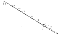
次に、本発明の好ましい実施の一例を図面を参照して説明する。図にあって1はループ成形材を示しており、この実施例におけるループ成形材1はナイロン製で、非延伸の線状となっている。このループ成形材1は一端に挿し込み部2が、他端には、この挿し込み部2が挿し込まれ、ロックしてループを完成する受部3が各々一体に設けられている。
Next, an example of a preferred embodiment of the present invention will be described with reference to the drawings. In the figure, reference numeral 1 denotes a loop molding material, and the loop molding material 1 in this embodiment is made of nylon and has a non-stretched linear shape. The loop molding 1 is integrally provided with an insertion portion 2 at one end, and at the other end, a receiving
また、前記したループ成形材1の挿し込み部2から受部3までの範囲には、挿し込み部2方向に向かって徐々に径を小さくする係合部4、4‥が連続して複数個、一体に形成されている。
Further, in the range from the insertion portion 2 to the
挿し込み部2は、一般的に使用されているような先端を錐状として挿入ガイドを形成しているものではなく、有底の円筒体5とし、その先端をフラットなものとし、前記円筒体5を180度のピッチ位置で二本のスリット6、6を入れて、押し縮められ、復元することのできる構成としてある。 The insertion portion 2 does not form an insertion guide with a generally used tip as a cone, but a bottomed cylindrical body 5 that has a flat tip, and the cylindrical body 5 is configured such that two slits 6 and 6 are inserted at a pitch position of 180 degrees, and can be compressed and restored.
受部3はループ成形材1の軸方向と直交方向に貫通孔7を設けてあり、挿し込み口8からは内部に向けて壁面に複数のスリット9、9‥を入れ、拡開復元を可能とした筒状の係止部10が一体に形成されている。また、挿し込み口8からはその係止部10の内面に先端が小径となるガイドテーパ11が形成されている。
The
このループ成形材1によってループを成形するには、対象の周囲にこのループ成形材1を回し、挿し込み部2を受部3の挿し込み口8から圧入挿入する。この際、逆方向から挿し込み部2を挿入しようとしても係止部10の頂面に挿し込み部2のフラットとした先端面が当接し、挿入はでき得ない。挿し込み口8から挿し込み部2を挿入すると、その挿し込み部2の先端はガイドテーパ11に沿って侵入し、係止部10を押し広げ、同時に挿し込み部2の円筒体5はガイドテーパ11から反作用でスリット6、6によりつぶされるように縮められる。そして、挿し込み部2の円筒体5が係止部10を通過すると、挿し込み部2の円筒体5及び係止部10は初期状態に復元し、円筒体5の底部が係止部10の頂面に係合されることで、引き抜きができないロック状態とされる。
In order to form a loop with the loop molding material 1, the loop molding material 1 is turned around the object, and the insertion portion 2 is press-fitted and inserted from the insertion port 8 of the
受部3の貫通孔7から突出された挿し込み部2をさらに引き、絞り込むと、係止部10をループ成形材1の係合部4、4‥が順次スリップしながら引き出され、目的とするループ径の位置で絞り込みを止めると、この係合部4、4の後端が係止部10の頂面と係合ロックされ、そのループ径の状態を維持することとなる。
When the insertion portion 2 protruding from the through hole 7 of the
さらに、受部3の外側面、即ち、ループ成形材1が設けられた位置と逆側の外面にはタグの取り付け部12が一体に設けられている。このタグの取り付け部12はフラットなもので、一対の板材の両縁が連結されて、後述するタグの舌片を挟持固着する構成となっている。このタグの取り付け部12の挟持部13の角度を受部3の貫通孔7の軸芯方向に対し、交差する位置、具体的には45度の角度をもって形成されたものとしている。
Further, a
また、前記したループ成形材1は図として示すナイロン製で連続した係合部を備えたものに代え、伸縮性を有するエラストマによって成形することもできる。このエラストマを用いた場合、それ自体に伸縮性があるため、連続した係合部は不要となり、また形成も紐状のほか、帯状として成形することができる。 Moreover, the above-mentioned loop molding material 1 can be molded by an elastomer having elasticity, instead of the nylon-made one having a continuous engagement portion. When this elastomer is used, since it itself has stretchability, a continuous engaging portion is not necessary, and the formation can be formed as a band shape in addition to a string shape.
一方、図中16は取り付けられるタグ、特にブランドタグを示しており、実施例では角丸の長方形板状をしているが、この形状は限定されるものではない。このタグ16は表面にブランド名、社名等の情報がプリントされており、ポリプロピレンをもって成形され、プリントされた表面は透明コーティングされ、水分によって劣化することのないよう図られている。
On the other hand,
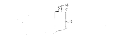
このタグ16には一縁に舌片14が一体に設けられており、実施例の場合、この舌片14にピンホール15が形成されている。このタグ16を取り付け部12の挟持部13に対し、インサート成形により、一体化するが、ポリプロピレンとナイロンでは素材的になじみが悪く、一体化が困難である。そのため、舌片14のピンホール15に対し、ポンチ等の治具を用いてもよいが、ループ成形材1の型による製作時に、ピンホール15内に挟持部13の素材を通入させて、抜け止めを図るものとしている。また、この抜け止めを図る手段として図16、図17に示す構成をとることもできる。図16として示す場合は舌片14の両側縁に括れ部17を形成し、前記したピンホール15の作用と同様にこの括れ部17に素材を通入させ、抜け止めとする。さらに、図17の場合は、舌片14の一部を切り起こし、切り起こし片18を一体に形成する。この場合、この切り起こし片18によっても素材を掛合させるが、切り起こし跡の透孔19内にも素材が通入することで抜けを防止できる。さらに、ここで示したピンホール15、括れ部17、切り起こし片18及び透孔19は、それぞれを組み合わせて構成することもできる。
The
なお、この型を用いてのループ成形材1の大量生産時に、同時にタグ16の取り付けをも行ない、製品化するについて、挟持部13が45度傾いているので、取り付けられるタグ16もそれに伴なって45度傾いた位置取りとなり、タグ16、16‥間のスペースが小さくでき、製作作業の省スペース化と、その後の包装、搬送等の作業も嵩張らず容易なものとなる。尚、前記したピンホール15の存在はこれに限られるものではなく、舌片14の両側縁に切り欠き状の括れ部分を形成し、この括れ部分で抜け止めを図ることもできる。
At the time of mass production of the loop molding material 1 using this mold, the
本実施例に係るタグ装着部材は上記のように構成されている。そのため、タグ16、特にブランドタグは強固に受部3に取り付けられ、搬送時等に離脱してしまうことはない。また、挿し込み部2の逆挿しが未然に防止されているので、ループ成形材1を無駄にしてしまうこともない。加えて、製造過程にあって、省スペース化を図ることもできる。
The tag mounting member according to the present embodiment is configured as described above. Therefore, the
本実施例に係るタグ装着部材は上記のように構成されている。この実施例ではループ成形材1として無延伸のナイロンを用いているが、これに限定されるものではなく、エラストマのほか、延伸処理を施し、引き絞りを特に行わない、ループ成形材として実施することも可能であり、係合部4も実施例に示した形態のほか、ビーズやラチェット等を利用するものでもよい。
The tag mounting member according to the present embodiment is configured as described above. In this embodiment, non-stretched nylon is used as the loop molding material 1, but the invention is not limited to this, and it is not limited to an elastomer, but is subjected to a stretching process and is not particularly drawn and is performed as a loop molding material. In addition to the form shown in the embodiment, the engaging
1 ループ成形材
2 挿し込み部
3 受部
4 係合部
5 円筒体
6 スリット
7 貫通孔
8 挿し込み口
9 スリット
10 係止部
11 ガイドテーパ
12 取り付け部
13 挟持部
14 舌片
15 ピンホール
16 タグ
17 括れ部
18 切り起こし片
19 透孔
DESCRIPTION OF SYMBOLS 1 Loop molding material 2
Claims (6)
Priority Applications (1)
| Application Number | Priority Date | Filing Date | Title |
|---|---|---|---|
| JP2010109930A JP5588735B2 (en) | 2010-05-12 | 2010-05-12 | Tag mounting member |
Applications Claiming Priority (1)
| Application Number | Priority Date | Filing Date | Title |
|---|---|---|---|
| JP2010109930A JP5588735B2 (en) | 2010-05-12 | 2010-05-12 | Tag mounting member |
Publications (2)
| Publication Number | Publication Date |
|---|---|
| JP2011237657A true JP2011237657A (en) | 2011-11-24 |
| JP5588735B2 JP5588735B2 (en) | 2014-09-10 |
Family
ID=45325689
Family Applications (1)
| Application Number | Title | Priority Date | Filing Date |
|---|---|---|---|
| JP2010109930A Active JP5588735B2 (en) | 2010-05-12 | 2010-05-12 | Tag mounting member |
Country Status (1)
| Country | Link |
|---|---|
| JP (1) | JP5588735B2 (en) |
Cited By (1)
| Publication number | Priority date | Publication date | Assignee | Title |
|---|---|---|---|---|
| JP2019200368A (en) * | 2018-05-18 | 2019-11-21 | 株式会社トスカバノック | Assembly of locking lock pin material and locking lock pin material |
Citations (8)
| Publication number | Priority date | Publication date | Assignee | Title |
|---|---|---|---|---|
| JPS4116318Y1 (en) * | 1964-11-24 | 1966-07-28 | ||
| JPS4739739Y1 (en) * | 1970-10-19 | 1972-12-01 | ||
| JPS5498200A (en) * | 1978-01-06 | 1979-08-02 | Clements Ben & Sons Inc | Device for mounting fine bar type including label and method of fabricating same |
| JPS54123978U (en) * | 1978-02-17 | 1979-08-30 | ||
| JPS5541847U (en) * | 1978-09-11 | 1980-03-18 | ||
| JPH1170968A (en) * | 1997-08-29 | 1999-03-16 | Hiromi Hizume | Sealer with indication function |
| JPH11292131A (en) * | 1998-04-13 | 1999-10-26 | Taiton Kk | Sealing device |
| JP2004231260A (en) * | 2003-01-31 | 2004-08-19 | S K Koki:Kk | Binding type closure and its manufacturing method |
-
2010
- 2010-05-12 JP JP2010109930A patent/JP5588735B2/en active Active
Patent Citations (8)
| Publication number | Priority date | Publication date | Assignee | Title |
|---|---|---|---|---|
| JPS4116318Y1 (en) * | 1964-11-24 | 1966-07-28 | ||
| JPS4739739Y1 (en) * | 1970-10-19 | 1972-12-01 | ||
| JPS5498200A (en) * | 1978-01-06 | 1979-08-02 | Clements Ben & Sons Inc | Device for mounting fine bar type including label and method of fabricating same |
| JPS54123978U (en) * | 1978-02-17 | 1979-08-30 | ||
| JPS5541847U (en) * | 1978-09-11 | 1980-03-18 | ||
| JPH1170968A (en) * | 1997-08-29 | 1999-03-16 | Hiromi Hizume | Sealer with indication function |
| JPH11292131A (en) * | 1998-04-13 | 1999-10-26 | Taiton Kk | Sealing device |
| JP2004231260A (en) * | 2003-01-31 | 2004-08-19 | S K Koki:Kk | Binding type closure and its manufacturing method |
Cited By (2)
| Publication number | Priority date | Publication date | Assignee | Title |
|---|---|---|---|---|
| JP2019200368A (en) * | 2018-05-18 | 2019-11-21 | 株式会社トスカバノック | Assembly of locking lock pin material and locking lock pin material |
| JP7102225B2 (en) | 2018-05-18 | 2022-07-19 | 株式会社トスカバノック | Assembly of locking pin material for locking and locking pin material for locking |
Also Published As
| Publication number | Publication date |
|---|---|
| JP5588735B2 (en) | 2014-09-10 |
Similar Documents
| Publication | Publication Date | Title |
|---|---|---|
| US7992263B2 (en) | Belt connector | |
| JP5904798B2 (en) | RFID tag and method of attaching the same | |
| US9802742B1 (en) | Elastic fastener and method of use | |
| EP3180252A1 (en) | Fastener assembly | |
| USD961373S1 (en) | Tie down fastener comprising a base with a cap | |
| JP5588735B2 (en) | Tag mounting member | |
| KR101739773B1 (en) | Connection member | |
| USD932883S1 (en) | Flexible band with identifying indicia | |
| WO2010034148A1 (en) | Fastener | |
| EP3046438B1 (en) | Fastening device | |
| US7654422B2 (en) | Needle threader | |
| JP2007044066A (en) | Tightening belt for baggage | |
| EP2656338B1 (en) | Wide filament fastener | |
| JP3193980U (en) | Tying tool | |
| JP5965784B2 (en) | Fastening band | |
| JP5512440B2 (en) | Fan and fan pattern | |
| CN101658349B (en) | Plate magnetic hasp | |
| JP5812875B2 (en) | RFID tag and method of attaching the same | |
| JP3237502U (en) | Document binding tool | |
| KR200422671Y1 (en) | Identification tag for quality control of farmed fish | |
| USD1058060S1 (en) | Pet wearable extending band | |
| JP6385022B1 (en) | Telescopic band | |
| JP3120094U (en) | Connecting member | |
| CN105857864A (en) | A self-supporting carton handle | |
| CN201131368Y (en) | Buckle binding structure for belt |
Legal Events
| Date | Code | Title | Description |
|---|---|---|---|
| A711 | Notification of change in applicant |
Free format text: JAPANESE INTERMEDIATE CODE: A712 Effective date: 20130321 |
|
| A621 | Written request for application examination |
Free format text: JAPANESE INTERMEDIATE CODE: A621 Effective date: 20130507 |
|
| A711 | Notification of change in applicant |
Free format text: JAPANESE INTERMEDIATE CODE: A712 Effective date: 20130510 |
|
| A521 | Request for written amendment filed |
Free format text: JAPANESE INTERMEDIATE CODE: A821 Effective date: 20130510 |
|
| A977 | Report on retrieval |
Free format text: JAPANESE INTERMEDIATE CODE: A971007 Effective date: 20131028 |
|
| A131 | Notification of reasons for refusal |
Free format text: JAPANESE INTERMEDIATE CODE: A131 Effective date: 20131030 |
|
| A521 | Request for written amendment filed |
Free format text: JAPANESE INTERMEDIATE CODE: A523 Effective date: 20131206 |
|
| TRDD | Decision of grant or rejection written | ||
| A01 | Written decision to grant a patent or to grant a registration (utility model) |
Free format text: JAPANESE INTERMEDIATE CODE: A01 Effective date: 20140702 |
|
| A61 | First payment of annual fees (during grant procedure) |
Free format text: JAPANESE INTERMEDIATE CODE: A61 Effective date: 20140728 |
|
| R150 | Certificate of patent or registration of utility model |
Ref document number: 5588735 Country of ref document: JP Free format text: JAPANESE INTERMEDIATE CODE: R150 |
|
| R250 | Receipt of annual fees |
Free format text: JAPANESE INTERMEDIATE CODE: R250 |
|
| R250 | Receipt of annual fees |
Free format text: JAPANESE INTERMEDIATE CODE: R250 |
|
| R250 | Receipt of annual fees |
Free format text: JAPANESE INTERMEDIATE CODE: R250 |
|
| S111 | Request for change of ownership or part of ownership |
Free format text: JAPANESE INTERMEDIATE CODE: R313113 |
|
| R360 | Written notification for declining of transfer of rights |
Free format text: JAPANESE INTERMEDIATE CODE: R360 |
|
| R370 | Written measure of declining of transfer procedure |
Free format text: JAPANESE INTERMEDIATE CODE: R370 |
|
| S111 | Request for change of ownership or part of ownership |
Free format text: JAPANESE INTERMEDIATE CODE: R313113 |
|
| S531 | Written request for registration of change of domicile |
Free format text: JAPANESE INTERMEDIATE CODE: R313531 |
|
| R350 | Written notification of registration of transfer |
Free format text: JAPANESE INTERMEDIATE CODE: R350 |
|
| R350 | Written notification of registration of transfer |
Free format text: JAPANESE INTERMEDIATE CODE: R350 |
|
| R250 | Receipt of annual fees |
Free format text: JAPANESE INTERMEDIATE CODE: R250 |
|
| R250 | Receipt of annual fees |
Free format text: JAPANESE INTERMEDIATE CODE: R250 |
|
| R250 | Receipt of annual fees |
Free format text: JAPANESE INTERMEDIATE CODE: R250 |
|
| R250 | Receipt of annual fees |
Free format text: JAPANESE INTERMEDIATE CODE: R250 |
|
| S802 | Written request for registration of partial abandonment of right |
Free format text: JAPANESE INTERMEDIATE CODE: R311802 |
|
| R350 | Written notification of registration of transfer |
Free format text: JAPANESE INTERMEDIATE CODE: R350 |
|
| R250 | Receipt of annual fees |
Free format text: JAPANESE INTERMEDIATE CODE: R250 |
|
| R250 | Receipt of annual fees |
Free format text: JAPANESE INTERMEDIATE CODE: R250 |