JP2011237704A - Video display device - Google Patents
Video display device Download PDFInfo
- Publication number
- JP2011237704A JP2011237704A JP2010110817A JP2010110817A JP2011237704A JP 2011237704 A JP2011237704 A JP 2011237704A JP 2010110817 A JP2010110817 A JP 2010110817A JP 2010110817 A JP2010110817 A JP 2010110817A JP 2011237704 A JP2011237704 A JP 2011237704A
- Authority
- JP
- Japan
- Prior art keywords
- luminance
- mirror
- light
- lamp
- video display
- Prior art date
- Legal status (The legal status is an assumption and is not a legal conclusion. Google has not performed a legal analysis and makes no representation as to the accuracy of the status listed.)
- Granted
Links
Images


Landscapes
- Transforming Electric Information Into Light Information (AREA)
- Projection Apparatus (AREA)
Abstract
【課題】アークジャンプが発生した場合に、映像輝度の低下を抑制することが可能な技術を提供することを目的とする。
【解決手段】映像表示装置は、ランプ2,3と、ミラー4と、ライトバルブ8と、輝度センサ10と、第1の調整手段11aと、第2の調整手段11bとを備える。輝度センサ10は、ライトバルブ8のオフステート光の輝度を検出する。第1の調整手段11aは、輝度センサ10で検出された輝度に基づいて、ミラー4の姿勢を所望に調整する。第2の調整手段11bは、第1の調整手段11aの調整後に輝度センサ10で検出された第1輝度と、第1輝度の検出から一定期間後に輝度センサ10で検出された第2輝度との間の輝度の低下度合が、予め設定された第1閾値を超えると判定される場合に、輝度センサ10で検出される輝度に基づいて、ミラー4の姿勢を再調整する。
【選択図】図1An object of the present invention is to provide a technique capable of suppressing a decrease in video luminance when an arc jump occurs.
An image display apparatus includes lamps 2, 3, a mirror 4, a light valve 8, a luminance sensor 10, a first adjustment unit 11a, and a second adjustment unit 11b. The luminance sensor 10 detects the luminance of the off-state light of the light valve 8. The first adjusting unit 11 a adjusts the attitude of the mirror 4 as desired based on the luminance detected by the luminance sensor 10. The second adjusting unit 11b is a first luminance detected by the luminance sensor 10 after the adjustment by the first adjusting unit 11a and a second luminance detected by the luminance sensor 10 after a certain period from the detection of the first luminance. When it is determined that the degree of decrease in luminance exceeds a preset first threshold value, the posture of the mirror 4 is readjusted based on the luminance detected by the luminance sensor 10.
[Selection] Figure 1
Description
本発明は、スクリーンに映像を投写する映像表示装置に関するものであり、特に映像の輝度が低下するのを抑制する映像表示装置に関するものである。 The present invention relates to an image display apparatus that projects an image on a screen, and more particularly to an image display apparatus that suppresses a decrease in the luminance of an image.
スクリーンに映像を投写する映像表示装置においては、複数のランプを備え、使用中のランプが故障した場合に、それとは別のランプを使用する技術が提案されている。特許文献1には、スクリーンにおける映像の輝度が低下した場合に、光路上に設けられたミラーの姿勢を変更して、別のランプを使用する映像表示装置が開示されている。
In an image display apparatus that projects an image on a screen, a technique has been proposed in which a plurality of lamps are provided, and when a lamp in use fails, a lamp different from the lamp is used.
さて、一般的な投写型の映像表示装置においては、ランプの電極が経時変化によって劣化することにより、その放電位置(発光位置)がずれる現象、いわゆるアークジャンプが発生することがある。このアークジャンプが発生すると、ランプ自体の輝度はほぼ変わらないが、ランプからの光の集光スポットがずれることから、スクリーンにおける映像輝度が低下するという問題があった。特に、特許文献1に開示されているようなランプを自動で切り替える映像表示装置においては、アークジャンプが発生して映像輝度が低下すると、使用しているランプ自体の輝度は低下していないにもかかわらず、別のランプを使用してしまう問題があった。
In a general projection-type image display device, a phenomenon in which a discharge position (light emission position) is shifted, that is, a so-called arc jump may occur due to deterioration of a lamp electrode due to aging. When this arc jump occurs, the brightness of the lamp itself is not substantially changed, but the light spot from the lamp is shifted, so that there is a problem that the brightness of the image on the screen is lowered. In particular, in an image display device that automatically switches lamps as disclosed in
そこで、本発明は、上記のような問題点を鑑みてなされたものであり、アークジャンプが発生した場合に、映像輝度の低下を抑制することが可能な技術を提供することを目的とする。 Therefore, the present invention has been made in view of the above problems, and an object of the present invention is to provide a technique capable of suppressing a decrease in video luminance when an arc jump occurs.
本発明に係る映像表示装置は、スクリーンに映像を投写する映像表示装置であって、光源部と、前記光源部からの光を反射するミラーと、前記ミラーからの反射光の光路上に配置され、受けた光を輝度変調するライトバルブと、前記ライトバルブのオフステート光の輝度を検出する輝度センサとを備える。そして、前記輝度センサで検出された輝度に基づいて、前記ミラーの姿勢を所望に調整する第1の調整手段と、前記第1の調整手段の調整後に前記輝度センサで検出された第1輝度と、当該第1輝度の検出から一定期間後に前記輝度センサで検出された第2輝度との間の輝度の低下度合が、予め設定された第1閾値を超えると判定される場合に、前記輝度センサで検出される輝度に基づいて、前記ミラーの姿勢を再調整する第2の調整手段とを備える。 An image display apparatus according to the present invention is an image display apparatus that projects an image on a screen, and is disposed on an optical path of a light source unit, a mirror that reflects light from the light source unit, and reflected light from the mirror. A light valve for modulating the received light in luminance and a luminance sensor for detecting the luminance of the off-state light of the light valve. And based on the brightness | luminance detected by the said brightness | luminance sensor, the 1st brightness | luminance detected by the said brightness | luminance sensor after the adjustment of the 1st adjustment means which adjusts the attitude | position of the said mirror as desired, and the said 1st adjustment means, When it is determined that the degree of decrease in brightness with respect to the second brightness detected by the brightness sensor after a certain period from the detection of the first brightness exceeds a preset first threshold value, the brightness sensor And a second adjusting means for readjusting the attitude of the mirror based on the luminance detected in step (b).
本発明によれば、第1輝度と第2輝度との間の輝度の低下度合が第1閾値を超える場合には、第2の調整手段がミラーの姿勢を再調整する。これにより、アークジャンプに起因する映像輝度の低下を抑制することができる。また、輝度が一定期間内において比較的大きく低下したときにのみミラー再調整を行うようにすることができることから、必要以上にミラー再調整が行われるのを抑制することができる。 According to the present invention, when the degree of decrease in luminance between the first luminance and the second luminance exceeds the first threshold value, the second adjusting means readjusts the mirror posture. Thereby, the fall of the image | video brightness resulting from an arc jump can be suppressed. Further, since the mirror readjustment can be performed only when the luminance is relatively lowered within a certain period, it is possible to suppress the mirror readjustment being performed more than necessary.
<実施の形態1>
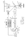
図1は本実施の形態に係る映像表示装置の構成を示すブロック図である。本実施の形態に係る映像表示装置は、モータ1と、複数の光源部たる二つのランプ2,3と、ミラー4と、ロッドインテグレータ5と、カラーホイール6と、リレーレンズ7と、ライトバルブ8と、投写レンズ9と、輝度センサ10と、制御手段たる制御回路11と、信号処理回路12とを備える。
<
FIG. 1 is a block diagram showing a configuration of a video display apparatus according to the present embodiment. The video display device according to the present embodiment includes a
この映像表示装置は、ランプ2,3のうち一方から出力された光を、ミラー4によってライトバルブ8に向けて反射させ、映像信号に基づいてライトバルブ8で強度変調する。そして、映像表示装置は、強度変調によって得られた光を投写レンズ9を介してスクリーン19に投写することにより、スクリーン19に映像を表示する。
In this video display device, light output from one of the
また、本実施の形態に係る映像表示装置においては、ランプ2,3のうち一方を使用している際に、経時変化や故障等によってスクリーン19における映像輝度が低くなった場合には他方を使用する。これにより、明るい輝度の映像表示を長く行なうことができるものとなっている。以下、本実施の形態に係る映像表示装置の構成について詳細に説明する。なお、以下の説明において、ランプ2,3のうち、映像表示装置が使用しているランプを「使用ランプ」と呼ぶこともある。
In the video display device according to the present embodiment, when one of the
ランプ2,3は互いに対向配置され、当該ランプ2,3同士の間にはミラー4が配置されている。ミラー4は、支持軸4aを介してモータ1と接続されている。モータ1が駆動されると、ミラー4が支持軸4aと一体となって支持軸4aの軸周りに回転する。このモータ1の駆動は、後述する制御回路11によって制御されることから、ミラー4の姿勢は、制御回路11によって調整(制御)されるものとなっている。ミラー4は、その反射面がランプ2,3のいずれか一方と対向するように、制御回路11により制御される。
The
ミラー4の反射面がランプ2と対向している場合にランプ2が点灯すると、ミラー4は、ランプ2からの光を反射してロッドインテグレータ5に導光する。この場合、ランプ2が使用ランプとなる。一方、ミラー4の反射面がランプ3と対向している場合にランプ3が点灯すると、ミラー4は、ランプ3からの光を反射してロッドインテグレータ5に導光する。この場合、ランプ3が使用ランプとなる。このように、ミラー4は、後続の部材たるロッドインテグレータ5に向けて、ランプ2,3からの光を選択的に反射することが可能となっている。
When the reflecting surface of the
ロッドインテグレータ5は、例えば、多角柱のガラスなどの光伝導部材からなり、一端に入射されたミラー4からの光に対して、輝度分布を均一化する処理を施しながら他端から出射する。ロッドインテグレータ5からの光は、カラーホイール6に入力される。
The
カラーホイール6は、回転軸の周方向に配列された、R(赤),G(緑),B(青)の3色のカラーフィルタ(図示せず)と、当該カラーフィルタを当該回転軸周りに回転させるホイールモータ(図示せず)とを備える。ロッドインテグレータ5からの光がR,G,Bのカラーフィルタのうちのいずれか一つを通過するように、カラーホイール6は配置されている。ホイールモータは、当該光が通過する一つのカラーフィルタを微小時間単位で順次に切り替えていくことから、カラーホイール6は、微小時間ごとに異なる色の光を順次出力することになる。カラーホイール6から出力された光は、リレーレンズ7に入力される。リレーレンズ7は、カラーホイール6からの光をライトバルブ8に出力する。
The
ライトバルブ8は、例えば、2次元的に配列された複数の微小ミラーを有するDMD(Digital Micromirror Device)であり、ミラー4からの反射光の光路上に配置されている。本実施の形態において、ライトバルブ8は、リレーレンズ7からの光を強度変調する。
The
信号処理回路12は、映像表示装置に入力される映像信号に応じてライトバルブ8の複数の微小ミラーのそれぞれをオン・オフ制御する。具体的には、微小ミラーは、信号処理回路12によりオン制御されると、リレーレンズ7からの光を投写レンズ9に向けて反射し、信号処理回路12によりオフ制御されると、リレーレンズ7からの光を投写レンズ9以外に向けて反射する。こうして、信号処理回路12がライトバルブ8の複数の微小ミラーを制御することにより、ライトバルブ8が、リレーレンズ7からの光を強度変調し、強度変調した当該光を投写レンズ9を介してスクリーン19に向けて投写することになる。
The
信号処理回路12の制御により、本実施の形態に係るライトバルブ8は、投写レンズ9に向けて強度変調した光を出力するオンステートと、当該光の光路外に設けられた輝度センサ10に向けてリレーレンズ7からの光を反射するオフステートとのいずれかを選択的にとるようになっている。
Under the control of the
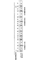
図2は、ライトバルブ8のオンステートとオフステートとを説明するためのタイミングチャートである。この図においては、映像信号の垂直同期信号に同期して、R,G,B光のそれぞれが3回ずつカラーホイール6から出力される例が示されている。つまり、1回転する間にR,G,B光のそれぞれを1回ずつ出力するカラーホイールが、映像信号の垂直同期信号に同期して3回転する例が図2に示されている。
FIG. 2 is a timing chart for explaining the on state and the off state of the
この図の下側には、オンステートが行われる期間であるオンステート期間41、及び、オフステートが行われる期間であるオフステート期間42が示されている。オフステート期間42は、R,G,Bのオンステート期間41とG,B,Rのオンステート期間41との境界のそれぞれにおいて設けられている。
On the lower side of the figure, an on-
各オンステート期間41では、ライトバルブ8が、リレーレンズ7からの光を映像信号に応じて強度変調し、それによって得られた光を、投写レンズ9を介してスクリーン19に投写する。以下、オンステート期間41にライトバルブ8から投写レンズ9に向かう光を「オンステート光」と呼ぶ。
In each on-
一方、各オフステート期間42では、ライトバルブ8が、リレーレンズ7からライトバルブ8に入力される光を、投写レンズ9ではなく、光の輝度を検出(計測)する輝度センサ10の方向に反射する。以下、オフステート期間42にライトバルブ8から輝度センサ10に向かう光を「オフステート光」と呼ぶ。
On the other hand, in each off-
オフステート期間42は前後する二つのオンステート期間41の境界に存在していることから、当該二つのオンステート期間41におけるオンステート光と同じ色のオフステート光が、当該オフステート期間42において輝度センサ10に入力される。例えば、R,Gのオンステート期間41の境界に存在するオフステート期間42においては、R,Gのオフステート光が輝度センサ10に入力される。同様にして、G,Bのオンステート期間41の境界に存在するオフステート期間42においてはG,Bのオフステート光が輝度センサ10に入力され、B,Rのオンステート期間41の境界に存在するオフステート期間42においてはB,Rのオフステート光が輝度センサ10に入力される。したがって、各R,G,Bのオフステート光が輝度センサ10に入力されることになる。
Since the off-
本実施の形態では、輝度センサ10は、R,G,B光をそれぞれ検出する3種類の輝度センサによって構成されており、R,G,B光の波長に対して個別に輝度値を計測可能となっている。そして、輝度センサ10は、前後する二つのオンステート期間41のうち、前方のオンステート期間41におけるオンステート光と同じ色のオフステート光の輝度を計測するものとなっている。例えば、R,Gのオンステート期間41の境界に存在するオフステート期間42においては、R,Gのオフステート光が輝度センサ10に入力されるが、R,Gのオンステート期間41のうち前方に位置するのはRのオンステート期間41であることから、輝度センサ10はRのオフステート光の輝度を計測する。同様に、輝度センサ10は、G,Bのオンステート期間41の境界に存在するオフステート期間42においてはGのオフステート光の輝度を計測し、B,Rのオンステート期間41の境界に存在するオフステート期間42においてはBのオフステート光の輝度を計測する。なお、オフステート光の輝度と、オンステート光の輝度とは実質的にほぼ同じであることから、輝度センサ10は、オフステート光の輝度に基づいて、オンステート光の輝度、つまり、スクリーン19における映像の輝度を計測することが可能となっている。
In the present embodiment, the
制御回路11は、輝度センサ10で計測されたR,G,Bのオフステート光の輝度を合算して合算輝度を取得し、その合算輝度に基づいて、ミラー4の姿勢を調整(制御)する。この合算輝度は、輝度センサ10で計測された輝度とほぼ同じ傾向を示すことから、実質的には、制御回路11は、輝度センサ10で計測(検出)された輝度に基づいて、ミラー4の姿勢を調整(制御)することになる。
The
この制御回路11は、例えば、CPU(図示しない)などから構成されており、CPUがメモリ(図示しない)に記憶されている動作プログラムを実行することによって、第1の調整手段11a、及び、第2の調整手段11bが制御回路11に機能ブロックとして形成される。
The
制御回路11は、合算輝度が低くなると、使用ランプを消灯してそれとは別のランプを点灯すると同時に、モータ1を制御して、ミラー4を支持軸4aの軸周りにほぼ180°回転させる。これにより使用ランプとは別のランプからの光は、ミラー4に反射されてロッドインテグレータ5に入射される。このように、制御回路11は、使用ランプを切り替えるランプチェンジを行う。制御回路11によるランプチェンジは、使用ランプの輝度が低下した場合だけでなく、使用ランプ切れ等により消灯した場合も同様に行われる。
When the combined luminance becomes low, the
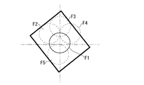
図3は、ロッドインテグレータ5において、使用ランプからの光がミラー4を介して入射される入射面を示す図である。図に示される5つの円は、当該入射面における使用ランプの光の入射スポットであり、最適な位置にある入射スポットF1が実線で、そこからずれた適当でない入射スポットF2〜F5が破線でそれぞれ示されている。
FIG. 3 is a diagram showing an incident surface on the
ランプチェンジ後の入射スポットは、製造時の誤差等により、入射スポットF2〜F5などになることが多い。しかし、この場合には、映像表示装置の輝度出力が低くなり、スクリーン19における映像の輝度が低くなってしまう。
Incident spots after the lamp change are often incident spots F2 to F5 and the like due to manufacturing errors and the like. However, in this case, the luminance output of the video display device is lowered, and the luminance of the video on the
そこで、第1の調整手段11a(制御回路11)は、ランプチェンジ後の入射スポットが最適な入射スポットF1に近づくように、合算輝度Ytに基づいて、ミラー4の回転位置を所望に調整する。
Therefore, the first adjusting means 11a (control circuit 11) adjusts the rotational position of the
図4は、合算輝度Ytと、ミラー4の回転位置との関係を示す図である。第1の調整手段11aは、モータ1を駆動して、ミラー4を1ステップ単位で回転させることにより、ミラー4の回転位置を下限Minpから上限Maxp(Minp<Maxp)まで変更することが可能となっている。第1の調整手段11aは、ミラー4を下限Minpから上限Maxpまで徐々に回転させながら、合算輝度とミラー4の回転位置とを一対一で取得し、その後、最大の合算輝度(以下、「最大合算輝度Ymax」と呼ぶ)が得られるミラー4の回転位置(以下、「最適回転位置Ypos」と呼ぶ)にミラー4を回転させる。これにより、入射スポットが最適な入射スポットF1に近づき、スクリーン19における映像の輝度を高めることができる。
FIG. 4 is a diagram showing the relationship between the combined luminance Yt and the rotational position of the
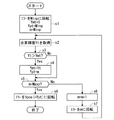
図5は、第1の調整手段11aがこのようなミラー調整を行う際の動作(アルゴリズム)を示すフローチャートである。以下、図5を用いて、この調整について説明する。なお、ステップs1の前には、制御回路11によってランプチェンジが行われ、そのランプチェンジから一定時間(使用ランプの出力が安定するのに必要な時間)が経過しているものとする。
FIG. 5 is a flowchart showing an operation (algorithm) when the
まず、ステップs1にて、第1の調整手段11aは、ミラー4の回転位置が下限Minpとなるようにミラー4を回転させる。その一方で、第1の調整手段11aは各データに初期値を入力する。具体的には、第1の調整手段11aは、現在のミラー4の回転位置mに下限Minpを代入し、現在までに得られた最大の合算輝度を示す暫定輝度最大値Ymtに0を代入し、暫定輝度最大値Ymに対応するミラー4の回転位置を示す暫定最適回転位置Yptに下限Minpを代入する。
First, in step s1, the
ステップs2にて、輝度センサ10が各R,G,Bの光の輝度を計測し、第1の調整手段11aがそれら輝度から合算輝度Ytを取得する。ステップs3にて、第1の調整手段11aは、当該合算輝度Ytが、暫定輝度最大値Ymtより大きいかを判定する。ステップs3において、合算輝度Ytが暫定輝度最大値Ymtより大きいと判定された場合にはステップs4に進み、そうでない場合にはステップs5に進む。なお、最初にステップs3が行われる場合には、暫定輝度最大値Ymtが0であることから、必ずステップs4に進むことになる。
In step s2, the
ステップs4にて、第1の調整手段11aは、暫定輝度最大値Ymtに現在の合算輝度Ytを代入して保持し、暫定最適回転位置Yptに現在のミラー4の回転位置mを代入して保持する。
In step s4, the
ステップs5にて、第1の調整手段11aは、現在のミラー4の回転位置mが上限Maxpであるかを判定する。ステップs5において、ミラー4の回転位置mが上限Maxpでないと判定した場合にはステップs6に進み、ミラー4の回転位置mが上限Maxpであると判定した場合にはステップs8に進む。
In step s5, the
ステップs6にて、第1の調整手段11aは、データ上の動作として、ミラー4の回転位置mを1ステップ進める(つまり、m=m+1とする)。そして、ステップs7にて、第1の調整手段11aは、物理的な動作として、更新された回転位置mが示す回転位置にミラー4を回転させる。それから、ステップs2に戻る。このようなステップs2〜ステップs7のループ処理を繰り返すことにより、ステップs5においてミラー4の回転位置mが上限Maxpであると判定される時点では、暫定輝度最大値Ymtが最大合算輝度Ymaxとなり、暫定最適回転位置Yptが最適回転位置Yposとなる。
In step s6, the
ステップs8においては、第1の調整手段11aは、ミラー4の回転位置がステップs5後の暫定最適回転位置Ypt(つまり最適回転位置Ypos)となるようにミラー4を回転させてミラー調整を終了する。
In step s8, the
この最適回転位置Yposは映像表示装置のメモリに記憶され、映像表示装置の電源が起動する際に、制御回路11はミラー4を最適回転位置Yposに回転する。
This optimal rotation position Ypos is stored in the memory of the video display device, and when the power supply of the video display device is activated, the
以上のような第1の調整手段11aのミラー調整により、スクリーン19における映像輝度を高めることが可能となる。しかし、使用ランプが一定期間使用されると、当該使用ランプにおいてアークジャンプが発生し、映像輝度が急に低下することがある。次に、アークジャンプについて説明する。
The image brightness on the
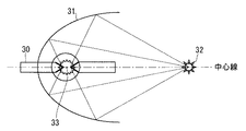
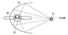
図6は、アークジャンプが発生する前の使用ランプの状態を示す図であり、図7は、アークジャンプが発生した後の使用ランプの状態を示す図である。以下、ランプ2が使用ランプである場合のアークジャンプを例に説明するが、ランプ3が使用ランプである場合のアークジャンプもそれと同様である。図6、図7に示されるように、ランプ2は、ランプ電極30と、当該ランプ電極30間における発光を集光点32に集光するリフレクタ31とを備える。
FIG. 6 is a diagram illustrating the state of the use lamp before the arc jump occurs, and FIG. 7 is a diagram illustrating the state of the use lamp after the arc jump occurs. Hereinafter, an arc jump when the
アークジャンプが発生する前には、図6に示されるように、ランプ2が、一点鎖線で示される中心線上の放電ポイント33において点灯し、集光点32が中心線上に位置している。しかし、アークジャンプが発生すると、図7に示されるように、ランプ2が、ランプ電極30間において中心線から例えば上側にずれた放電ポイント33において点灯することから、集光点32が中心線から下側に位置することになる。このように、アークジャンプが発生すると、ランプ2の集光点32(集光スポット)が、発生前後において急にずれてしまうことから、アークジャンプ発生前において入射スポットが最適であったとしても、アークジャンプ発生後においては最適でなくなり、その結果、映像輝度が急に低下してしまうことになる。
Before the arc jump occurs, as shown in FIG. 6, the
そこで、本実施の形態に係る映像表示装置においては、制御回路11が、輝度センサ10を用いて合算輝度を一定期間ごとに取得する。つまり、制御回路11が、第1合算輝度と、当該第1合算輝度の取得から一定期間後に取得される第2合算輝度とをつぎつぎと取得していく。そして、第1合算輝度と第2合算輝度との間の合算輝度Ytの低下度合が、予め設定された第1閾値を超えると判定される場合に、第2の調整手段11b(制御回路11)が、第1の調整手段11aと同様にミラー4の調整を行う。つまり、アークジャンプによりランプ電極30間の放電位置が変わった場合に、第2の調整手段11bがミラー4の再調整を行う。これにより、アークジャンプによる映像輝度の低下を抑制可能となっている。
Therefore, in the video display device according to the present embodiment, the
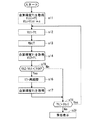
図8は、本実施の形態に係る映像表示装置の上述の動作を示すフローチャートである。以下、図8を用いて、その動作について説明する。なお、ステップs11の前には、制御回路11によってランプチェンジが行われ、第1の調整手段11aによってミラー4が調整されたものとする。
FIG. 8 is a flowchart showing the above-described operation of the video display apparatus according to the present embodiment. Hereinafter, the operation will be described with reference to FIG. Before step s11, it is assumed that the lamp change is performed by the
まず、ステップs11にて、輝度センサ10が各R,G,Bの光の輝度を計測し、制御回路11がそれら輝度から合算輝度Ytを取得する。そして、制御回路11は、初期値として、ランプ点灯初期の輝度を示す初期輝度データYiniに当該合算輝度Ytを代入し、ランプチェンジを行うための第2閾値Ytcに「Yini×c」を代入する。ここで、cは、予め決められた1より小さい固定値である。
First, in step s11, the
ステップs12にて、制御回路11は、第1合算輝度Yt1に、前回取得された合算輝度Ytを代入して記憶する。ここで、ステップs11の後に本ステップs12が行われる場合には、ステップs11の合算輝度Ytが、前回取得された合算輝度Ytとして用いられ、後述するステップ18の後に本ステップs12が行われる場合には、後述するステップs14またはステップs17の合算輝度Ytが、前回取得された合算輝度Ytとして用いられる。
In step s12, the
ステップs13にて、ミラー調整の動作が一定期間(例えば2分間)停止する待ち状態となる。当該一定期間経過後に、ステップs14にて、輝度センサ10が各R,G,Bの光の輝度を計測し、制御回路11がそれら輝度から合算輝度Ytを取得し、第2合算輝度Yt2に当該合算輝度Ytを代入する。
In step s13, the mirror adjustment operation enters a waiting state in which it is stopped for a certain period (for example, 2 minutes). After the fixed period has elapsed, in step s14, the
ステップs15にて、制御回路11は、第2合算輝度Yt2を第1合算輝度Yt1によって除算することによって輝度比Yr(=Yt2/Yt1)を取得する。輝度比Yrが大きいことは、第1合算輝度Yt1と第2合算輝度Yt2との間の合算輝度Ytの低下度合が小さいことを示し、輝度比Yrが小さいことは、第1合算輝度Yt1と第2合算輝度Yt2との間の合算輝度Ytの低下度合が大きいことを示す。
In step s15, the
同ステップs15にて、制御回路11は、輝度比Yrが予め設定された第1閾値Thよりも小さいかを判定する。つまり、制御回路11は、第1合算輝度Yt1と第2合算輝度Yt2との間の合算輝度Ytの低下度合が第1閾値Thを超えるかを判定する。
In step s15, the
ステップs15において、輝度比Yrが第1閾値Thよりも小さい場合には、合算輝度Ytの変化度合が第1閾値Thよりも大きいと判断し、ステップs16に進む。そして、ステップs16にて、第2の調整手段11bは、ステップs1〜s8(図5)と同様に、合算輝度Ytに基づいて、ミラー4の姿勢を再調整する。ステップs16の後、ステップs17にて、輝度センサ10が各R,G,Bの光の輝度を計測し、制御回路11がそれら輝度から合算輝度Ytを取得する。ステップs17の後、ステップs18に進む。
If the luminance ratio Yr is smaller than the first threshold Th in step s15, it is determined that the degree of change in the combined luminance Yt is larger than the first threshold Th, and the process proceeds to step s16. In step s16, the second adjustment unit 11b readjusts the attitude of the
ステップs15において、輝度比Yrが第1閾値Th以上と判定された場合には、合算輝度Ytの変化度合が第1閾値Th以下であると判断し、ミラー再調整を行わずにステップs18に進む。 If it is determined in step s15 that the luminance ratio Yr is greater than or equal to the first threshold Th, it is determined that the degree of change in the combined luminance Yt is less than or equal to the first threshold Th, and the process proceeds to step s18 without performing mirror readjustment. .
ステップs15直後にステップs18に進んだ場合には、当該ステップs18にて、制御回路11は、第1閾値Thを超えないとステップs15にて判定された低下度合に係る第2合算輝度Yt2(つまり、ステップs14の合算輝度Yt)が、予め設定された第2閾値Ytcよりも大きいかを判定する。一方、ステップs17直後にステップs18に進んだ場合には、当該ステップs18にて、制御回路11は、第2の調整手段11bの調整直後のステップs17の合算輝度Ytが、予め設定された第2閾値Ytcよりも大きいかを判定する。
When the process proceeds to step s18 immediately after step s15, in step s18, the
ステップs18において、合算輝度Ytが第2閾値Ytcよりも大きいと判定された場合には、ランプチェンジから現在までの間における使用ランプ自体の輝度低下が小さいことから、使用ランプを引き続き使用可能と判断し、ステップs12に戻る。 If it is determined in step s18 that the combined luminance Yt is greater than the second threshold Ytc, it is determined that the used lamp can continue to be used because the decrease in luminance of the used lamp itself from the lamp change to the present is small. Then, the process returns to step s12.
ステップs18において、合算輝度Ytが第2閾値Ytc以下であると判定された場合には、使用ランプが寿命に達したと判断し、ステップs19に進む。 If it is determined in step s18 that the combined luminance Yt is equal to or less than the second threshold value Ytc, it is determined that the lamp in use has reached the end of life, and the process proceeds to step s19.
ステップs19にて、制御回路11は、使用ランプとは別のランプからの光を、ミラー4が反射するようにミラー4の姿勢を制御する。つまり、制御回路11が、ランプチェンジを行う。その後、第1の調整手段11aが、使用ランプからの光の入射スポットが最適となるようにステップs1〜s8のミラー調整を行い、再び、ステップs11以降の動作が行われる。
In step s19, the
以上のようなミラー再調整において、例えば第1閾値Th=0.7である際に、第2合算輝度Yt2の低下幅が第1合算輝度Yt1の30%以上となる場合には、ステップs16にてミラー再調整が行われる。そして、例えばc=0.5(つまり、第2閾値Ytc=Yini×0.5)である際に、ステップs14またはステップs17の合算輝度Ytの低下幅が初期輝度データYiniの50%以上となる場合には、使用ランプが寿命に達したと判断し、ステップs19にてランプチェンジが行われる。 In the mirror readjustment as described above, for example, when the first threshold Th is 0.7, when the decrease width of the second total luminance Yt2 is 30% or more of the first total luminance Yt1, the process proceeds to step s16. Mirror readjustment. For example, when c = 0.5 (that is, the second threshold value Ytc = Yini × 0.5), the reduction width of the combined luminance Yt in step s14 or step s17 is 50% or more of the initial luminance data Yini. In this case, it is determined that the lamp used has reached the end of its life, and a lamp change is performed in step s19.
以上のような本実施の形態に係る映像表示装置によれば、第1合算輝度Yt1と第2合算輝度Yt2との間の合算輝度Ytの低下度合が第1閾値Thを超える場合には、第2の調整手段11bがミラー4の回転位置を再調整する。これにより、アークジャンプに起因する映像輝度の低下を抑制することができる。また、第1閾値Thを適当に大きな値にすれば、合算輝度Ytが一定期間内において比較的大きく低下したときにのみミラー再調整を行うようにすることができる。したがって、合算輝度Ytがゆっくりと低下する場合にミラー再調整が行われるのを抑制することができることから、必要以上にミラー再調整が行われるのを抑制することができる。
According to the video display device according to the present embodiment as described above, when the degree of decrease in the combined luminance Yt between the first combined luminance Yt1 and the second combined luminance Yt2 exceeds the first threshold Th, The second adjusting unit 11b readjusts the rotational position of the
また、本実施の形態に係る映像表示装置によれば、アークジャンプに起因して映像輝度の低下が発生した場合にはミラー4の回転位置を再調整し、使用ランプ自体の輝度低下に起因して映像輝度の低下が発生した場合にはランプチェンジを行うことができる。これにより、使用ランプがまだ使用可能であるのに、ランプチェンジをしてしまうのを防ぐことができる。よって、不要な動作を防ぐことができるので省エネルギー化を実現することができる。
Further, according to the video display apparatus according to the present embodiment, when the video brightness is reduced due to the arc jump, the rotation position of the
なお、上述の説明においては、輝度センサ10は、前後する二つのオンステート期間41のうち、前方のオンステート期間41におけるオンステート光と同じ色のオフステート光の輝度を計測するものとした(図2)。しかし、例えば、後方のオフステート期間41におけるオンステート光と同じ色のオフステート光の輝度を計測するというように、オフステート期間42内であれば上述とは別のタイミングで輝度を計測してもよい。また、制御回路11、第1及び第2の調整手段11a,11bは、輝度センサ10が検出するR,G,Bの光のそれぞれの輝度を合算した合算輝度に基づいてミラー4の姿勢を調整(制御)していたが、R,G,Bの光のいずれか一つの輝度、例えば、Bの光の輝度に基づいてミラー4の姿勢を調整(制御)するものであってもよい。この場合、輝度センサ10には、単色の光の輝度を検出するセンサを用いることができる。
In the above description, the
<実施の形態2>
図9は、本実施の形態に係る映像表示装置の構成を示すブロック図である。なお、以下の本実施の形態に係る映像表示装置の説明において、実施の形態1に係る映像表示装置と共通する部分については同じ符号を付すものとし、重複する説明は省略する。
<
FIG. 9 is a block diagram showing a configuration of the video display apparatus according to the present embodiment. In the following description of the video display device according to the present embodiment, parts that are the same as those of the video display device according to the first embodiment are denoted by the same reference numerals, and redundant description is omitted.
実施の形態1に係る映像表示装置はランプ2,3を備えていたが、本実施の形態に係る映像表示装置は、それらの代わりに一つのランプ2を備えている。そして、本実施の形態に係る映像表示装置においては、その構成に、警告通知手段13が追加されている。
Although the video display apparatus according to the first embodiment includes the
本映像表示装置においては、実施の形態1に係る映像表示装置と同様に、第1の調整手段11aがランプ使用開始の際にミラー調整して映像輝度を高め、第2の調整手段11bがミラー再調整してアークジャンプによる映像輝度の低下を抑制する。ただし、実施の形態1では、合算輝度Ytが第2閾値Ytcよりも小さくなった場合には制御回路11がランプチェンジを行ったが、本実施の形態では、この場合に警告通知手段13が警告を表示画面に表示して外部に通知する。
In the present video display device, similarly to the video display device according to the first embodiment, the
図10は、本実施の形態に係る映像表示装置の動作を示すフローチャートである。以下、図10を用いて、その動作について説明する。なお、この図10に示されるフローは、図8に示されるフローのステップs19を、ステップs29に置き換えたものであるから、以下の説明においては、その前のステップs18と、当該ステップs29とについてのみ説明する。 FIG. 10 is a flowchart showing the operation of the video display apparatus according to this embodiment. Hereinafter, the operation will be described with reference to FIG. The flow shown in FIG. 10 is obtained by replacing step s19 of the flow shown in FIG. 8 with step s29. Therefore, in the following description, the previous step s18 and the step s29 will be described. Only explained.
ステップs15直後にステップs18に進んだ場合には、当該ステップs18にて、制御回路11は、第1閾値Thを超えないとステップs15にて判定された低下度合に係る第2合算輝度Yt2(つまり、ステップs14の合算輝度Yt)が、予め設定された第2閾値Ytcよりも大きいかを判定する。一方、ステップs17直後にステップs18に進んだ場合には、当該ステップs18にて、制御回路11は、第2の調整手段11bの調整直後のステップs17の合算輝度Ytが、予め設定された第2閾値Ytcよりも大きいかを判定する。
When the process proceeds to step s18 immediately after step s15, in step s18, the
ステップs18において合算輝度Ytが第2閾値Ytcよりも大きいと判定された場合には、ランプ点灯開始時点から現在までの間における使用ランプ自体の輝度低下が小さいことから、使用ランプを引き続き使用可能と判断し、ステップs12に戻る。一方、ステップs18において合算輝度Ytが第2閾値Ytc以下であると判定された場合には、使用ランプが寿命に達したと判断し、ステップs29に進む。ステップs29にて、警告通知手段13は、ランプ交換を促す警告表示を行う。 If it is determined in step s18 that the combined luminance Yt is greater than the second threshold value Ytc, since the decrease in luminance of the used lamp itself is small from the lamp lighting start time to the present time, it is possible to continue using the used lamp. Determination is made and the process returns to step s12. On the other hand, if it is determined in step s18 that the combined luminance Yt is less than or equal to the second threshold value Ytc, it is determined that the lamp in use has reached the end of life, and the process proceeds to step s29. In step s29, the warning notification means 13 displays a warning for prompting lamp replacement.
以上のような本実施の形態に係る映像表示装置によれば、ランプチェンジを行わないことを除いて、実施の形態1に係る映像表示装置と同様の効果を得ることができる。 According to the video display device according to the present embodiment as described above, the same effects as those of the video display device according to the first embodiment can be obtained except that the lamp change is not performed.
また、本実施の形態に係る映像表示装置によれば、正しくランプ交換を促す警告を通知することができる。つまり、アークジャンプが発生して使用ランプ自体の輝度が低下していないにもかかわらず、ランプ交換を促す警告を通知してしまうことを抑制することができる。 Further, according to the video display apparatus according to the present embodiment, it is possible to notify a warning prompting correct lamp replacement. That is, it is possible to suppress a warning for prompting lamp replacement even though the arc jump has occurred and the brightness of the lamp itself has not decreased.
なお、ランプチェンジを行う実施の形態1に係る映像表示装置においても、本実施の形態に係る映像表示装置が備える警告通知手段13を加えてもよい。この場合には、ランプチェンジ後の新しい使用ランプを点灯させながら、寿命に達したランプを交換する警告を行うことができる。 In the video display device according to the first embodiment that performs the lamp change, the warning notification means 13 included in the video display device according to the present embodiment may be added. In this case, a warning can be given to replace the lamp that has reached the end of its life while lighting a new lamp that has been used after the lamp change.
2,3 ランプ、4 ミラー、8 ライトバルブ、10 輝度センサ、11 制御回路、11a 第1の調整手段、11b 第2の調整手段、13 警告通知手段、19 スクリーン。 2, 3 lamps, 4 mirrors, 8 light valves, 10 brightness sensors, 11 control circuit, 11a first adjustment means, 11b second adjustment means, 13 warning notification means, 19 screen.
Claims (3)
光源部と、
前記光源部からの光を反射するミラーと、
前記ミラーからの反射光の光路上に配置され、受けた光を輝度変調するライトバルブと、
前記ライトバルブのオフステート光の輝度を検出する輝度センサと、
前記輝度センサで検出された輝度に基づいて、前記ミラーの姿勢を所望に調整する第1の調整手段と、
前記第1の調整手段の調整後に前記輝度センサで検出された第1輝度と、当該第1輝度の検出から一定期間後に前記輝度センサで検出された第2輝度との間の輝度の低下度合が、予め設定された第1閾値を超えると判定される場合に、前記輝度センサで検出される輝度に基づいて、前記ミラーの姿勢を再調整する第2の調整手段と
を備える、映像表示装置。 An image display device that projects an image on a screen,
A light source unit;
A mirror that reflects light from the light source unit;
A light valve that is arranged on the optical path of the reflected light from the mirror and modulates the intensity of the received light;
A brightness sensor for detecting the brightness of the off-state light of the light valve;
First adjusting means for adjusting the position of the mirror as desired based on the luminance detected by the luminance sensor;
The degree of decrease in luminance between the first luminance detected by the luminance sensor after the adjustment of the first adjusting means and the second luminance detected by the luminance sensor after a certain period of time from the detection of the first luminance. A video display device comprising: a second adjustment unit that adjusts the attitude of the mirror again based on the luminance detected by the luminance sensor when it is determined that the predetermined first threshold value is exceeded.
前記光源部は複数設けられ、
前記ミラーは、複数の前記光源部のうちの一つの光源部からの光を反射し、
前記第1閾値を超えないと判定された前記低下度合に係る前記第2輝度、または、前記第2の調整手段の調整直後に前記輝度センサで検出された輝度が、予め設定された第2閾値よりも小さいと判定される場合に、前記複数の光源部のうち前記一つの光源部とは別の光源部からの光を前記ミラーが反射するように当該ミラーの姿勢を制御する制御手段を備える、映像表示装置。 The video display device according to claim 1,
A plurality of the light source units are provided,
The mirror reflects light from one of the plurality of light source units,
The second luminance relating to the degree of decrease determined not to exceed the first threshold, or the luminance detected by the luminance sensor immediately after adjustment of the second adjustment means is a preset second threshold. Control means for controlling the attitude of the mirror so that the mirror reflects light from a light source unit different from the one light source unit among the plurality of light source units. , Video display device.
前記第1閾値を超えないと判定された前記低下度合に係る前記第2輝度、または、前記第2の調整手段の調整直後に前記輝度センサで検出された輝度が、予め設定された第2閾値よりも小さいと判定される場合に、当該判定の結果に基づいて警告を外部に通知する警告通知手段をさらに備える、映像表示装置。 The video display device according to claim 1 or 2,
The second luminance relating to the degree of decrease determined not to exceed the first threshold, or the luminance detected by the luminance sensor immediately after adjustment of the second adjustment means is a preset second threshold. A video display device further comprising warning notification means for notifying a warning to the outside based on a result of the determination when it is determined to be smaller than that.
Priority Applications (1)
| Application Number | Priority Date | Filing Date | Title |
|---|---|---|---|
| JP2010110817A JP5424979B2 (en) | 2010-05-13 | 2010-05-13 | Video display device |
Applications Claiming Priority (1)
| Application Number | Priority Date | Filing Date | Title |
|---|---|---|---|
| JP2010110817A JP5424979B2 (en) | 2010-05-13 | 2010-05-13 | Video display device |
Publications (2)
| Publication Number | Publication Date |
|---|---|
| JP2011237704A true JP2011237704A (en) | 2011-11-24 |
| JP5424979B2 JP5424979B2 (en) | 2014-02-26 |
Family
ID=45325726
Family Applications (1)
| Application Number | Title | Priority Date | Filing Date |
|---|---|---|---|
| JP2010110817A Expired - Fee Related JP5424979B2 (en) | 2010-05-13 | 2010-05-13 | Video display device |
Country Status (1)
| Country | Link |
|---|---|
| JP (1) | JP5424979B2 (en) |
Citations (3)
| Publication number | Priority date | Publication date | Assignee | Title |
|---|---|---|---|---|
| JPH08292495A (en) * | 1995-04-20 | 1996-11-05 | Fujitsu General Ltd | Light source for projection |
| JP2004343581A (en) * | 2003-05-19 | 2004-12-02 | Mitsubishi Electric Corp | Multi-screen display device |
| WO2005073799A1 (en) * | 2004-01-28 | 2005-08-11 | Matsushita Electric Industrial Co., Ltd. | Projection display and image display method |
-
2010
- 2010-05-13 JP JP2010110817A patent/JP5424979B2/en not_active Expired - Fee Related
Patent Citations (3)
| Publication number | Priority date | Publication date | Assignee | Title |
|---|---|---|---|---|
| JPH08292495A (en) * | 1995-04-20 | 1996-11-05 | Fujitsu General Ltd | Light source for projection |
| JP2004343581A (en) * | 2003-05-19 | 2004-12-02 | Mitsubishi Electric Corp | Multi-screen display device |
| WO2005073799A1 (en) * | 2004-01-28 | 2005-08-11 | Matsushita Electric Industrial Co., Ltd. | Projection display and image display method |
Also Published As
| Publication number | Publication date |
|---|---|
| JP5424979B2 (en) | 2014-02-26 |
Similar Documents
| Publication | Publication Date | Title |
|---|---|---|
| US7753554B2 (en) | Light source apparatus | |
| US8324828B2 (en) | High-pressure discharge lamp lighting device, high pressure discharge lamp apparatus using this, projector using the high-pressure discharge lamp apparatus, and high-pressure discharge lamp lighting method | |
| US7946715B2 (en) | Light source and projector | |
| US8129927B2 (en) | Driving device and driving method of electric discharge lamp, light source device, and image display apparatus | |
| US7841723B2 (en) | Projector using lamp, method and program for controlling discharge lamp light source | |
| JP2009237302A (en) | Image projecting device, and light source lighting device for projector | |
| KR20070076338A (en) | Video playback device and control method | |
| JP5446721B2 (en) | Discharge lamp lighting device and projection-type image display device | |
| EP2328019A1 (en) | Image projector | |
| JP5424977B2 (en) | Video display device | |
| JP2010039047A (en) | Projector, and control method and control program of projector | |
| JP2007187750A (en) | Projection apparatus and projection method | |
| JP5424979B2 (en) | Video display device | |
| US9706181B2 (en) | Projector with a plurality of light sources having dimming capabilities | |
| JP5501859B2 (en) | Video display device | |
| JP2007124767A (en) | Electrical equipment | |
| JP2009053452A (en) | Image projection device | |
| JP2005227748A (en) | Projection type vido display device | |
| JP5375115B2 (en) | Projection apparatus, projection method, and program | |
| JP5195323B2 (en) | Projection-type image display device | |
| JP2006301228A (en) | Projector | |
| JP5256827B2 (en) | Projection apparatus, projection method, and program | |
| JP2011053610A (en) | Projection video display device | |
| JP2009026746A (en) | projector | |
| JP2007155952A (en) | Projection type system by high-pressure discharge lamp |
Legal Events
| Date | Code | Title | Description |
|---|---|---|---|
| A621 | Written request for application examination |
Free format text: JAPANESE INTERMEDIATE CODE: A621 Effective date: 20130128 |
|
| A977 | Report on retrieval |
Free format text: JAPANESE INTERMEDIATE CODE: A971007 Effective date: 20131021 |
|
| TRDD | Decision of grant or rejection written | ||
| A01 | Written decision to grant a patent or to grant a registration (utility model) |
Free format text: JAPANESE INTERMEDIATE CODE: A01 Effective date: 20131029 |
|
| A61 | First payment of annual fees (during grant procedure) |
Free format text: JAPANESE INTERMEDIATE CODE: A61 Effective date: 20131126 |
|
| R150 | Certificate of patent or registration of utility model |
Free format text: JAPANESE INTERMEDIATE CODE: R150 Ref document number: 5424979 Country of ref document: JP Free format text: JAPANESE INTERMEDIATE CODE: R150 |
|
| R250 | Receipt of annual fees |
Free format text: JAPANESE INTERMEDIATE CODE: R250 |
|
| R250 | Receipt of annual fees |
Free format text: JAPANESE INTERMEDIATE CODE: R250 |
|
| R250 | Receipt of annual fees |
Free format text: JAPANESE INTERMEDIATE CODE: R250 |
|
| R250 | Receipt of annual fees |
Free format text: JAPANESE INTERMEDIATE CODE: R250 |
|
| R250 | Receipt of annual fees |
Free format text: JAPANESE INTERMEDIATE CODE: R250 |
|
| LAPS | Cancellation because of no payment of annual fees |