JP2012005264A - Dcdcコンバータ - Google Patents
Dcdcコンバータ Download PDFInfo
- Publication number
- JP2012005264A JP2012005264A JP2010138733A JP2010138733A JP2012005264A JP 2012005264 A JP2012005264 A JP 2012005264A JP 2010138733 A JP2010138733 A JP 2010138733A JP 2010138733 A JP2010138733 A JP 2010138733A JP 2012005264 A JP2012005264 A JP 2012005264A
- Authority
- JP
- Japan
- Prior art keywords
- transformer
- current
- power converter
- switching elements
- source power
- Prior art date
- Legal status (The legal status is an assumption and is not a legal conclusion. Google has not performed a legal analysis and makes no representation as to the accuracy of the status listed.)
- Granted
Links
Images

Classifications
-
- H—ELECTRICITY
- H02—GENERATION; CONVERSION OR DISTRIBUTION OF ELECTRIC POWER
- H02M—APPARATUS FOR CONVERSION BETWEEN AC AND AC, BETWEEN AC AND DC, OR BETWEEN DC AND DC, AND FOR USE WITH MAINS OR SIMILAR POWER SUPPLY SYSTEMS; CONVERSION OF DC OR AC INPUT POWER INTO SURGE OUTPUT POWER; CONTROL OR REGULATION THEREOF
- H02M3/00—Conversion of DC power input into DC power output
- H02M3/22—Conversion of DC power input into DC power output with intermediate conversion into AC
- H02M3/24—Conversion of DC power input into DC power output with intermediate conversion into AC by static converters
- H02M3/28—Conversion of DC power input into DC power output with intermediate conversion into AC by static converters using discharge tubes with control electrode or semiconductor devices with control electrode to produce the intermediate AC
- H02M3/325—Conversion of DC power input into DC power output with intermediate conversion into AC by static converters using discharge tubes with control electrode or semiconductor devices with control electrode to produce the intermediate AC using devices of a triode or a transistor type requiring continuous application of a control signal
- H02M3/335—Conversion of DC power input into DC power output with intermediate conversion into AC by static converters using discharge tubes with control electrode or semiconductor devices with control electrode to produce the intermediate AC using devices of a triode or a transistor type requiring continuous application of a control signal using semiconductor devices only
- H02M3/33569—Conversion of DC power input into DC power output with intermediate conversion into AC by static converters using discharge tubes with control electrode or semiconductor devices with control electrode to produce the intermediate AC using devices of a triode or a transistor type requiring continuous application of a control signal using semiconductor devices only having several active switching elements
- H02M3/33576—Conversion of DC power input into DC power output with intermediate conversion into AC by static converters using discharge tubes with control electrode or semiconductor devices with control electrode to produce the intermediate AC using devices of a triode or a transistor type requiring continuous application of a control signal using semiconductor devices only having several active switching elements having at least one active switching element at the secondary side of an isolation transformer
- H02M3/33584—Bidirectional converters
-
- H—ELECTRICITY
- H02—GENERATION; CONVERSION OR DISTRIBUTION OF ELECTRIC POWER
- H02M—APPARATUS FOR CONVERSION BETWEEN AC AND AC, BETWEEN AC AND DC, OR BETWEEN DC AND DC, AND FOR USE WITH MAINS OR SIMILAR POWER SUPPLY SYSTEMS; CONVERSION OF DC OR AC INPUT POWER INTO SURGE OUTPUT POWER; CONTROL OR REGULATION THEREOF
- H02M1/00—Details of apparatus for conversion
- H02M1/40—Means for preventing magnetic saturation
Landscapes
- Engineering & Computer Science (AREA)
- Power Engineering (AREA)
- Dc-Dc Converters (AREA)
- Rectifiers (AREA)
Abstract
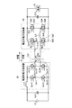
【解決手段】直流を交流に変換する電流形電力変換器2と、電流形電力変換器2から出力された交流を変圧するトランスT1と、トランスT1にて変圧された交流を直流に変換する整流器3と、整流器3側のトランス巻線に直列に接続され、トランスT1に印加される直流成分を遮断するコンデンサC3とを備える。
【選択図】 図1
Description
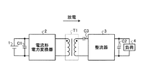
図1において、このDCDCコンバータには、直流を交流に変換する電流形電力変換器2と、電流形電力変換器2から出力された交流を変圧するトランスT1と、トランスT1にて変圧された交流を直流に変換する整流器3およびトランスT1に印加される直流成分を遮断するコンデンサC3が設けられている。なお、電流形電力変換器2は、スイッチング素子のオン/オフによってトランスT1の1次側に流れる電流を制御することで、電力変換を行うことができる。
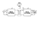
図2において、このDCDCコンバータでは、図1の整流器3の代わりに電圧形電力変換器5が設けられている。なお、電圧形電力変換器5は、スイッチング素子のオン/オフによってトランスT1の2次側に印加される電圧を制御することで、電力変換を行うことができる。
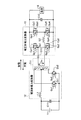
図3において、このDCDCコンバータには、トランスT11と、トランスT11の1次側に接続された電流形電力変換器12と、トランスT11の2次側に接続された電圧形電力変換器15が設けられている。
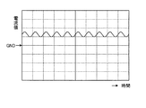
図4において、図3のコンデンサC13がある場合、励磁電流Imの直流成分が除去されている。このため、コンデンサC13を設けることでトランスT11の偏磁を低減させることができる。
図5において、図3のコンデンサC13がない場合、励磁電流Imに直流成分が重畳され、トランスT11の偏磁の要因となる。
図6において、このDCDCコンバータでは、図3の電流形電力変換器12およびトランスT11の代わりに電流形電力変換器22およびトランスT21が設けられている。なお、その他の構成は図3と同様である。
2、12、22 電流形電力変換器
3 整流器
4、6、16 負荷
5、15 電圧形電力変換器
T1、T11、T21 トランス
C1、C2、C11、C12 平滑コンデンサ
C3、C13、Cp1〜Cp4 コンデンサ
L1、L2、L3 インダクタ
Ds1、Ds2、Dp1〜Dp4、Dp11〜Dp14 還流ダイオード
Qs1、Qs2、Qp1〜Qp4、Qp11〜Qp14 スイッチング素子
Claims (5)
- 直流を交流に変換する電流形電力変換器と、
前記電流形電力変換器から出力された交流を変圧するトランスと、
前記トランスにて変圧された交流を直流に変換する整流器と、
前記整流器側のトランス巻線に直列に接続され、前記トランスに印加される直流成分を遮断するコンデンサとを備えることを特徴とするDCDCコンバータ。 - 直流を交流に変換する電流形電力変換器と、
前記電流形電力変換器から出力された交流を変圧するトランスと、
前記トランスにて変圧された交流を直流に変換する電圧形電力変換器と、
前記電圧形電力変換器側のトランス巻線に直列に接続され、前記トランスに印加される直流成分を遮断するコンデンサとを備えることを特徴とするDCDCコンバータ。 - 前記電圧形電力変換器は、
第1および第2のスイッチング素子が互いに直列に接続された第1の直列回路と、
第3および第4のスイッチング素子が互いに直列に接続された第2の直列回路とを備え、
前記第1の直列回路と前記第2の直列回路とは互いに並列に接続され、
前記第1および第2のスイッチング素子の接続点と、前記第3および第4のスイッチング素子の接続点との間に前記トランスの2次巻線が設けられていることを特徴とする請求項2に記載のDCDCコンバータ。 - 前記電流形電力変換器は、
直流電源からの電流を前記トランスの1次巻線の中間タップに供給するインダクタと、
前記1次巻線の一端と前記直流電源の負極側との間に接続された第5のスイッチング素子と、
前記1次巻線の他端と前記直流電源の負極側との間に接続された第6のスイッチング素子とを備えることを特徴とする請求項1から3のいずれか1項に記載のDCDCコンバータ。 - 前記電流形電力変換器は、
第5のスイッチング素子と第6のスイッチング素子とが互いに直列に接続された第3の直列回路と、
第7および第8のスイッチング素子が互いに直列に接続された第4の直列回路とを備え、
前記第3の直列回路と前記第4の直列回路とは互いに並列に接続され、
前記第5および第6のスイッチング素子の接続点と、前記第7および第8のスイッチング素子の接続点との間に前記トランスの1次巻線が設けられ、
前記第5および第7のスイッチング素子の接続点と前記直流電源の正極側との間にインダクタが設けられていることを特徴とする請求項1から3のいずれか1項に記載のDCDCコンバータ。
Priority Applications (2)
| Application Number | Priority Date | Filing Date | Title |
|---|---|---|---|
| JP2010138733A JP5185327B2 (ja) | 2010-06-17 | 2010-06-17 | Dcdcコンバータ |
| US13/158,811 US8576582B2 (en) | 2010-06-17 | 2011-06-13 | DC-DC converter |
Applications Claiming Priority (1)
| Application Number | Priority Date | Filing Date | Title |
|---|---|---|---|
| JP2010138733A JP5185327B2 (ja) | 2010-06-17 | 2010-06-17 | Dcdcコンバータ |
Publications (2)
| Publication Number | Publication Date |
|---|---|
| JP2012005264A true JP2012005264A (ja) | 2012-01-05 |
| JP5185327B2 JP5185327B2 (ja) | 2013-04-17 |
Family
ID=45328522
Family Applications (1)
| Application Number | Title | Priority Date | Filing Date |
|---|---|---|---|
| JP2010138733A Active JP5185327B2 (ja) | 2010-06-17 | 2010-06-17 | Dcdcコンバータ |
Country Status (2)
| Country | Link |
|---|---|
| US (1) | US8576582B2 (ja) |
| JP (1) | JP5185327B2 (ja) |
Cited By (4)
| Publication number | Priority date | Publication date | Assignee | Title |
|---|---|---|---|---|
| KR101457887B1 (ko) | 2012-12-28 | 2014-11-20 | 서울과학기술대학교 산학협력단 | 공진형 dc-dc 컨버터 및 이를 이용한 인터리빙 공진형 dc-dc 컨버터 |
| KR20160066099A (ko) * | 2014-12-01 | 2016-06-10 | 한국전기연구원 | 직류 배전용 양방향 컨버터의 출력 평형 및 단락 보호 회로 |
| JP2016111898A (ja) * | 2014-12-10 | 2016-06-20 | 株式会社豊田中央研究所 | 電力変換回路システム |
| WO2019167271A1 (ja) * | 2018-03-02 | 2019-09-06 | 三菱電機株式会社 | 電力変換装置 |
Families Citing this family (3)
| Publication number | Priority date | Publication date | Assignee | Title |
|---|---|---|---|---|
| DE102011003576A1 (de) * | 2011-02-03 | 2012-08-09 | Robert Bosch Gmbh | Gegentaktwandler und Modulationsverfahren zum Ansteuern eines Gegentaktwandlers |
| CN104796028B (zh) * | 2014-01-21 | 2018-10-23 | 北京动力源科技股份有限公司 | 一种全桥电路及含有该电路的大功率直流电源 |
| US11575326B2 (en) * | 2020-11-27 | 2023-02-07 | Lear Corporation | Wide high voltage-input range DC-DC converter |
Citations (5)
| Publication number | Priority date | Publication date | Assignee | Title |
|---|---|---|---|---|
| JPH09168278A (ja) * | 1995-12-13 | 1997-06-24 | Yuasa Corp | フルブリッジ形スイッチングレギュレータの偏磁防止回路 |
| JPH1198835A (ja) * | 1997-09-19 | 1999-04-09 | Toyota Autom Loom Works Ltd | Hブリッジ昇圧回路 |
| JP2003164151A (ja) * | 2001-11-28 | 2003-06-06 | Nissin Electric Co Ltd | Dc−dcコンバータ |
| JP2005110384A (ja) * | 2003-09-30 | 2005-04-21 | Hitachi Ltd | Dc−dcコンバータ |
| JP2006524883A (ja) * | 2003-04-29 | 2006-11-02 | ニューセルシス ゲーエムベーハー | 一体型燃料電池ベースの電源用のパワーコンバータアーキテクチャ及び方法 |
Family Cites Families (3)
| Publication number | Priority date | Publication date | Assignee | Title |
|---|---|---|---|---|
| US4257087A (en) * | 1979-04-02 | 1981-03-17 | California Institute Of Technology | DC-to-DC switching converter with zero input and output current ripple and integrated magnetics circuits |
| DE102006025975B4 (de) * | 2006-06-02 | 2008-08-28 | Siemens Ag Österreich | Wechselrichterschaltung und Verfahren zum Betreiben der Wechselrichterschaltung |
| US7778046B1 (en) * | 2008-12-17 | 2010-08-17 | Slobodan Cuk | Voltage step-up switching DC-to-DC converter field of the invention |
-
2010
- 2010-06-17 JP JP2010138733A patent/JP5185327B2/ja active Active
-
2011
- 2011-06-13 US US13/158,811 patent/US8576582B2/en not_active Expired - Fee Related
Patent Citations (5)
| Publication number | Priority date | Publication date | Assignee | Title |
|---|---|---|---|---|
| JPH09168278A (ja) * | 1995-12-13 | 1997-06-24 | Yuasa Corp | フルブリッジ形スイッチングレギュレータの偏磁防止回路 |
| JPH1198835A (ja) * | 1997-09-19 | 1999-04-09 | Toyota Autom Loom Works Ltd | Hブリッジ昇圧回路 |
| JP2003164151A (ja) * | 2001-11-28 | 2003-06-06 | Nissin Electric Co Ltd | Dc−dcコンバータ |
| JP2006524883A (ja) * | 2003-04-29 | 2006-11-02 | ニューセルシス ゲーエムベーハー | 一体型燃料電池ベースの電源用のパワーコンバータアーキテクチャ及び方法 |
| JP2005110384A (ja) * | 2003-09-30 | 2005-04-21 | Hitachi Ltd | Dc−dcコンバータ |
Cited By (6)
| Publication number | Priority date | Publication date | Assignee | Title |
|---|---|---|---|---|
| KR101457887B1 (ko) | 2012-12-28 | 2014-11-20 | 서울과학기술대학교 산학협력단 | 공진형 dc-dc 컨버터 및 이를 이용한 인터리빙 공진형 dc-dc 컨버터 |
| KR20160066099A (ko) * | 2014-12-01 | 2016-06-10 | 한국전기연구원 | 직류 배전용 양방향 컨버터의 출력 평형 및 단락 보호 회로 |
| KR102204941B1 (ko) | 2014-12-01 | 2021-01-20 | 한국전기연구원 | 직류 배전용 양방향 컨버터의 출력 평형 및 단락 보호 회로 |
| JP2016111898A (ja) * | 2014-12-10 | 2016-06-20 | 株式会社豊田中央研究所 | 電力変換回路システム |
| WO2019167271A1 (ja) * | 2018-03-02 | 2019-09-06 | 三菱電機株式会社 | 電力変換装置 |
| JPWO2019167271A1 (ja) * | 2018-03-02 | 2021-02-04 | 三菱電機株式会社 | 電力変換装置 |
Also Published As
| Publication number | Publication date |
|---|---|
| JP5185327B2 (ja) | 2013-04-17 |
| US8576582B2 (en) | 2013-11-05 |
| US20110310636A1 (en) | 2011-12-22 |
Similar Documents
| Publication | Publication Date | Title |
|---|---|---|
| US9479073B2 (en) | Gate drive apparatus for resonant converters | |
| JP5088386B2 (ja) | スイッチング電源装置 | |
| CN101578758B (zh) | 开关电源装置 | |
| Hsieh et al. | An interleaved flyback converter featured with zero-voltage transition | |
| JP5185327B2 (ja) | Dcdcコンバータ | |
| JP5914989B2 (ja) | スイッチング電源装置 | |
| US20150124487A1 (en) | Adjustable Resonant Apparatus for Power Converters | |
| WO2015067202A2 (en) | Startup method and system for resonant converters | |
| JP5790889B2 (ja) | スイッチング電源装置およびac−dc電力変換システム | |
| US20120113686A1 (en) | Virtual parametric high side mosfet driver | |
| US20120044729A1 (en) | Bridgeless coupled inductor boost power factor rectifiers | |
| JP6667750B1 (ja) | Dc−dcコンバータ | |
| TW201524103A (zh) | 直流電源轉換裝置與方法 | |
| JP2014007914A (ja) | Dc−dcコンバータ | |
| JP2012085465A (ja) | 電源装置 | |
| TWI454038B (zh) | 三相電源轉換電路及其軟式切換電路 | |
| JP2015154525A (ja) | 双方向フライバックコンバータ | |
| KR20150070898A (ko) | 직류-직류 컨버터 및 이의 스위칭 방법 | |
| JP2015050890A (ja) | スイッチング電源装置 | |
| JP5578234B2 (ja) | スイッチング電源装置およびこれを用いた電源システム、電子装置 | |
| RU2464692C1 (ru) | Преобразователь напряжения (варианты) | |
| Tibola et al. | Passive regenerative snubber cell applied to isolated DCM SEPIC converter | |
| KR101442553B1 (ko) | 전원회로 | |
| Delshad et al. | A new active clamping soft switching weinberg converter | |
| Cetin | High efficiency design considerations for the self-driven synchronous rectified phase-shifted full-bridge converters of server power systems |
Legal Events
| Date | Code | Title | Description |
|---|---|---|---|
| A977 | Report on retrieval |
Free format text: JAPANESE INTERMEDIATE CODE: A971007 Effective date: 20120404 |
|
| A131 | Notification of reasons for refusal |
Free format text: JAPANESE INTERMEDIATE CODE: A131 Effective date: 20120410 |
|
| A521 | Request for written amendment filed |
Free format text: JAPANESE INTERMEDIATE CODE: A523 Effective date: 20120611 |
|
| TRDD | Decision of grant or rejection written | ||
| A01 | Written decision to grant a patent or to grant a registration (utility model) |
Free format text: JAPANESE INTERMEDIATE CODE: A01 Effective date: 20130108 |
|
| A61 | First payment of annual fees (during grant procedure) |
Free format text: JAPANESE INTERMEDIATE CODE: A61 Effective date: 20130117 |
|
| R150 | Certificate of patent or registration of utility model |
Ref document number: 5185327 Country of ref document: JP Free format text: JAPANESE INTERMEDIATE CODE: R150 Free format text: JAPANESE INTERMEDIATE CODE: R150 |
|
| FPAY | Renewal fee payment (event date is renewal date of database) |
Free format text: PAYMENT UNTIL: 20160125 Year of fee payment: 3 |
|
| RD05 | Notification of revocation of power of attorney |
Free format text: JAPANESE INTERMEDIATE CODE: A7425 Effective date: 20130614 |
|
| A072 | Dismissal of procedure [no reply to invitation to correct request for examination] |
Free format text: JAPANESE INTERMEDIATE CODE: A072 Effective date: 20131008 |
|
| R250 | Receipt of annual fees |
Free format text: JAPANESE INTERMEDIATE CODE: R250 |
|
| R250 | Receipt of annual fees |
Free format text: JAPANESE INTERMEDIATE CODE: R250 |