JP2012009596A - Liquid supply apparatus, exposure equipment, liquid supply method, maintenance method, and method of manufacturing device - Google Patents
Liquid supply apparatus, exposure equipment, liquid supply method, maintenance method, and method of manufacturing device Download PDFInfo
- Publication number
- JP2012009596A JP2012009596A JP2010143727A JP2010143727A JP2012009596A JP 2012009596 A JP2012009596 A JP 2012009596A JP 2010143727 A JP2010143727 A JP 2010143727A JP 2010143727 A JP2010143727 A JP 2010143727A JP 2012009596 A JP2012009596 A JP 2012009596A
- Authority
- JP
- Japan
- Prior art keywords
- liquid
- substrate
- exposure
- exposure light
- predetermined gas
- Prior art date
- Legal status (The legal status is an assumption and is not a legal conclusion. Google has not performed a legal analysis and makes no representation as to the accuracy of the status listed.)
- Pending
Links
Images


Landscapes
- Exposure Of Semiconductors, Excluding Electron Or Ion Beam Exposure (AREA)
- Exposure And Positioning Against Photoresist Photosensitive Materials (AREA)
Abstract
【課題】露光不良の発生を抑制できる液体供給装置を提供する。
【解決手段】液体供給装置は、光学部材の射出面から射出される露光光で液体を介して基板を露光する露光装置に使用される。液体供給装置は、脱気処理された液体に溶存する所定ガス濃度を高める処理を実行する液体処理装置を備え、所定ガス濃度が高められた液体を露光光の光路の少なくとも一部に供給可能である。
【選択図】図1
A liquid supply apparatus capable of suppressing the occurrence of exposure failure is provided.
A liquid supply apparatus is used in an exposure apparatus that exposes a substrate through a liquid with exposure light emitted from an emission surface of an optical member. The liquid supply apparatus includes a liquid processing apparatus that executes a process for increasing a predetermined gas concentration dissolved in the degassed liquid, and is capable of supplying the liquid with the predetermined gas concentration increased to at least a part of the optical path of the exposure light. is there.
[Selection] Figure 1
Description
本発明は、液体供給装置、露光装置、液体供給方法、メンテナンス方法、及びデバイス製造方法に関する。 The present invention relates to a liquid supply apparatus, an exposure apparatus, a liquid supply method, a maintenance method, and a device manufacturing method.
フォトリソグラフィ工程で用いられる露光装置において、例えば特許文献1に開示されているような、液体を介して露光光で基板を露光する液浸露光装置が知られている。 As an exposure apparatus used in a photolithography process, for example, an immersion exposure apparatus that exposes a substrate with exposure light via a liquid as disclosed in Patent Document 1 is known.
液浸露光装置において、所望状態で液体が供給されないと、その液体を用いる処理を良好に実行できなくなる可能性がある。例えば、液体を用いて露光装置の部材をメンテナンスする場合において、所望状態で液体が供給されないと、そのメンテナンスを良好に実行できなくなる可能性がある。その結果、露光装置の性能が低下し、露光不良が発生したり、不良デバイスが発生したりする可能性がある。 In a liquid immersion exposure apparatus, if a liquid is not supplied in a desired state, there is a possibility that processing using that liquid cannot be performed satisfactorily. For example, when maintaining a member of an exposure apparatus using a liquid, if the liquid is not supplied in a desired state, the maintenance may not be performed satisfactorily. As a result, there is a possibility that the performance of the exposure apparatus is deteriorated and an exposure failure occurs or a defective device occurs.
本発明の態様は、露光不良の発生を抑制できる液体供給装置、露光装置、液体供給方法、及びメンテナンス方法を提供することを目的とする。また本発明の態様は、不良デバイスの発生を抑制できるデバイス製造方法を提供することを目的とする。 An aspect of the present invention is to provide a liquid supply apparatus, an exposure apparatus, a liquid supply method, and a maintenance method that can suppress the occurrence of exposure failure. Another object of the present invention is to provide a device manufacturing method that can suppress the occurrence of defective devices.
本発明の第1の態様に従えば、光学部材の射出面から射出される露光光で液体を介して基板を露光する露光装置に使用される液体供給装置であって、脱気処理された液体に溶存する所定ガス濃度を高める処理を実行する液体処理装置を備え、所定ガス濃度が高められた液体を露光光の光路の少なくとも一部に供給可能である液体供給装置が提供される。 According to the first aspect of the present invention, there is provided a liquid supply apparatus for use in an exposure apparatus that exposes a substrate through exposure liquid that is emitted from an emission surface of an optical member. There is provided a liquid supply apparatus that includes a liquid processing apparatus that executes a process for increasing the concentration of a predetermined gas dissolved in the liquid, and that can supply a liquid with an increased predetermined gas concentration to at least a part of an optical path of exposure light.
本発明の第2の態様に従えば、光学部材の射出面から射出される露光光で液体を介して基板を露光する露光装置に使用される液体供給装置であって、基板の表面に射出面からの露光光が照射されるときに、射出面と基板の表面との間の露光光の光路に第1供給量で液体を供給し、射出面と対向する位置を含む所定面内において移動する露光装置が有する部材の表面に射出面からの露光光が照射されるときに、射出面と部材の表面との間の光路に第1供給量よりも少ない第2供給量で液体を供給する液体供給装置が提供される。 According to the second aspect of the present invention, there is provided a liquid supply apparatus for use in an exposure apparatus that exposes a substrate through a liquid with exposure light emitted from an emission surface of an optical member, the emission surface on the surface of the substrate. Liquid is supplied at a first supply amount to the optical path of the exposure light between the exit surface and the surface of the substrate and moves within a predetermined plane including a position facing the exit surface. Liquid that supplies a liquid with a second supply amount smaller than the first supply amount to the optical path between the emission surface and the surface of the member when exposure light from the emission surface is irradiated onto the surface of the member of the exposure apparatus A feeding device is provided.
本発明の第3の態様に従えば、液体を介して露光光で基板を露光する露光装置であって、第1、第2の態様の液体供給装置を備える露光装置が提供される。 According to a third aspect of the present invention, there is provided an exposure apparatus that exposes a substrate with exposure light through a liquid, the exposure apparatus including the liquid supply device according to the first and second aspects.
本発明の第4の態様に従えば、第3の態様の露光装置を用いて基板を露光することと、露光された基板を現像することと、を含むデバイス製造方法が提供される。 According to a fourth aspect of the present invention, there is provided a device manufacturing method including exposing a substrate using the exposure apparatus according to the third aspect and developing the exposed substrate.
本発明の第5の態様に従えば、光学部材の射出面から射出される露光光で液体を介して基板を露光する露光装置に使用される液体供給方法であって、脱気処理された液体に溶存する所定ガス濃度を高めることと、所定ガス濃度が高められた液体を射出面と露光装置が有する部材の表面との間の露光光の光路の少なくとも一部に供給することと、を含む液体供給方法が提供される。 According to a fifth aspect of the present invention, there is provided a liquid supply method used in an exposure apparatus that exposes a substrate through exposure liquid emitted from an emission surface of an optical member, and the liquid subjected to deaeration treatment And increasing a predetermined gas concentration dissolved in the liquid, and supplying a liquid having the increased predetermined gas concentration to at least a part of an optical path of exposure light between the exit surface and the surface of a member of the exposure apparatus. A liquid supply method is provided.
本発明の第6の態様に従えば、光学部材の射出面から射出される露光光で液体を介して基板を露光する露光装置に使用される液体供給方法であって、射出面と対向する位置を含む所定面内において移動する露光装置が有する部材の表面に射出面からの露光光が照射されるときに、射出面と部材の表面との間に、基板の表面に射出面からの露光光が照射されるときに射出面と基板の表面との間に供給される第1供給量よりも少ない第2供給量で液体を供給することを含む液体供給方法が提供される。 According to a sixth aspect of the present invention, there is provided a liquid supply method used in an exposure apparatus that exposes a substrate through a liquid with exposure light emitted from an emission surface of an optical member, the position facing the emission surface. Exposure light from the exit surface to the surface of the substrate between the exit surface and the surface of the member when the exposure light from the exit surface is irradiated on the surface of the member of the exposure apparatus that moves within a predetermined plane including A liquid supply method is provided that includes supplying the liquid with a second supply amount that is less than the first supply amount supplied between the emission surface and the surface of the substrate when the liquid is irradiated.
本発明の第7の態様に従えば、光学部材の射出面から射出される露光光で液体を介して基板を露光する露光装置のメンテナンス方法であって、第5、第6の態様の液体供給方法で液体を供給することと、液体を介して部材に露光光を照射して部材をクリーニングすることと、を含むメンテナンス方法が提供される。 According to a seventh aspect of the present invention, there is provided an exposure apparatus maintenance method for exposing a substrate through a liquid with exposure light emitted from an emission surface of an optical member, wherein the liquid supply according to the fifth and sixth aspects is provided. There is provided a maintenance method including supplying a liquid by the method and cleaning the member by irradiating the member with exposure light through the liquid.
本発明の第8の態様に従えば、第7の態様のメンテナンス方法でメンテナンスされた露光装置を用いて基板を露光することと、露光された基板を現像することと、を含むデバイス製造方法が提供される。 According to an eighth aspect of the present invention, there is provided a device manufacturing method comprising: exposing a substrate using the exposure apparatus maintained by the maintenance method of the seventh aspect; and developing the exposed substrate. Provided.
本発明の態様によれば、露光不良の発生を抑制できる。また本発明の態様によれば、不良デバイスの発生を抑制できる。 According to the aspect of the present invention, it is possible to suppress the occurrence of exposure failure. Moreover, according to the aspect of the present invention, the occurrence of defective devices can be suppressed.
以下、本発明の実施形態について図面を参照しながら説明するが、本発明はこれに限定されない。以下の説明においては、XYZ直交座標系を設定し、このXYZ直交座標系を参照しつつ各部の位置関係について説明する。水平面内の所定方向をX軸方向、水平面内においてX軸方向と直交する方向をY軸方向、X軸方向及びY軸方向のそれぞれと直交する方向(すなわち鉛直方向)をZ軸方向とする。また、X軸、Y軸、及びZ軸まわりの回転(傾斜)方向をそれぞれ、θX、θY、及びθZ方向とする。 Hereinafter, embodiments of the present invention will be described with reference to the drawings, but the present invention is not limited thereto. In the following description, an XYZ orthogonal coordinate system is set, and the positional relationship of each part will be described with reference to this XYZ orthogonal coordinate system. A predetermined direction in the horizontal plane is defined as an X-axis direction, a direction orthogonal to the X-axis direction in the horizontal plane is defined as a Y-axis direction, and a direction orthogonal to each of the X-axis direction and the Y-axis direction (that is, a vertical direction) is defined as a Z-axis direction. Further, the rotation (inclination) directions around the X axis, Y axis, and Z axis are the θX, θY, and θZ directions, respectively.
<第1実施形態>
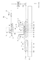
第1実施形態について説明する。図1は、第1実施形態に係る露光装置EXを示す概略構成図である。本実施形態の露光装置EXは、液体LQを介して露光光ELで基板Pを露光する液浸露光装置である。
<First Embodiment>
A first embodiment will be described. FIG. 1 is a schematic block diagram that shows an exposure apparatus EX according to the first embodiment. The exposure apparatus EX of the present embodiment is an immersion exposure apparatus that exposes a substrate P with exposure light EL through a liquid LQ.
また、本実施形態の露光装置EXは、例えば米国特許第6897963号明細書、欧州特許出願公開第1713113号明細書等に開示されているような、基板Pを保持して移動可能な基板ステージ2と、基板Pを保持せずに、露光光ELを計測する計測部材C(計測器)を搭載して移動可能な計測ステージ3とを備えた露光装置である。
Further, the exposure apparatus EX of the present embodiment has a
図1において、露光装置EXは、マスクMを保持して移動可能なマスクステージ1と、基板ステージ2と、計測ステージ3と、マスクMを露光光ELで照明する照明系ILと、露光光ELで照明されたマスクMのパターンの像を基板Pに投影する投影光学系PLと、露光光ELの光路の少なくとも一部が液体LQで満たされるように液浸空間LSを形成可能な液浸部材4と、露光光ELの光路の少なくとも一部に液体LQを供給可能な液体供給装置5と、液体LQを回収可能な液体回収装置6と、露光装置EX全体の動作を制御する制御装置7とを備えている。
In FIG. 1, an exposure apparatus EX includes a mask stage 1 that can move while holding a mask M, a
液浸空間は、液体で満たされた空間である。本実施形態においては、液体LQとして、水(純水)を用いる。マスクMは、基板Pに投影されるデバイスパターンが形成されたレチクルを含む。基板Pは、デバイスを製造するための基板である。基板Pは、例えば半導体ウエハ等の基材と、その基材上に形成された感光膜とを含む。感光膜は、感光材(フォトレジスト)の膜である。 The immersion space is a space filled with liquid. In the present embodiment, water (pure water) is used as the liquid LQ. The mask M includes a reticle on which a device pattern projected onto the substrate P is formed. The substrate P is a substrate for manufacturing a device. The substrate P includes, for example, a base material such as a semiconductor wafer and a photosensitive film formed on the base material. The photosensitive film is a film of a photosensitive material (photoresist).
照明系ILは、所定の照明領域IRに露光光ELを照射する。照明領域IRは、照明系ILから射出される露光光ELが照射可能な位置を含む。照明系ILは、照明領域IRに配置されたマスクMの少なくとも一部を露光光ELで照明する。照明系ILから射出される露光光ELとして、例えば水銀ランプから射出される輝線(g線、h線、i線)及びKrFエキシマレーザ光(波長248nm)等の遠紫外光(DUV光)、ArFエキシマレーザ光(波長193nm)、及びF2レーザ光(波長157nm)等の真空紫外光(VUV光)等が用いられる。本実施形態においては、露光光ELとして、紫外光(真空紫外光)であるArFエキシマレーザ光を用いる。 The illumination system IL irradiates the predetermined illumination area IR with the exposure light EL. The illumination area IR includes a position where the exposure light EL emitted from the illumination system IL can be irradiated. The illumination system IL illuminates at least a part of the mask M arranged in the illumination area IR with the exposure light EL. As the exposure light EL emitted from the illumination system IL, for example, far ultraviolet light (DUV light) such as bright lines (g line, h line, i line) and KrF excimer laser light (wavelength 248 nm) emitted from a mercury lamp, ArF Excimer laser light (wavelength 193 nm), vacuum ultraviolet light (VUV light) such as F 2 laser light (wavelength 157 nm), or the like is used. In the present embodiment, ArF excimer laser light, which is ultraviolet light (vacuum ultraviolet light), is used as the exposure light EL.
マスクステージ1は、マスクMを保持した状態で、照明領域IRを含むベース部材8のガイド面8G上を移動可能である。マスクステージ1は、例えば平面モータを含むステージ駆動システムの作動により、ガイド面8G上において、X軸、Y軸、Z軸、θX、θY、及びθZ方向の6つの方向に移動可能である。
The mask stage 1 is movable on the
投影光学系PLは、所定の投影領域PRに露光光ELを照射する。投影光学系PLは、投影光学系PLの像面に向けて露光光ELを射出する射出面10を有する。投影光学系PLの複数の光学素子のうち、投影光学系PLの像面に最も近い終端光学素子11が射出面10を有する。投影領域PRは、射出面10から射出される露光光ELが照射可能な位置を含む。投影光学系PLは、投影領域PRに配置された基板Pの少なくとも一部に、マスクMのパターンの像を所定の投影倍率で投影する。本実施形態において、終端光学素子11の光軸は、Z軸と平行である。本実施形態において、射出面10から射出される露光光ELは、−Z方向に進行する。
The projection optical system PL irradiates the predetermined projection region PR with the exposure light EL. The projection optical system PL has an
基板ステージ2は、基板Pを保持した状態で、投影領域PRを含むベース部材12のガイド面12G上を移動可能である。計測ステージ3は、計測部材Cを保持した状態で、投影領域PRを含むベース部材12のガイド面12G上を移動可能である。基板ステージ2及び計測ステージ3のそれぞれは、例えば平面モータを含むステージ駆動システムの作動により、ガイド面12G上において、X軸、Y軸、Z軸、θX、θY、及びθZ方向の6つの方向に移動可能である。
The
本実施形態において、基板ステージ2は、基板Pをリリース可能に保持する保持部13を有する。計測ステージ3は、計測部材Cをリリース可能に保持する保持部14を有する。本実施形態において、基板ステージ2は、米国特許出願公開第2007/0177125号明細書、及び米国特許出願公開第2008/0049209号明細書等に開示されているような、保持部13の周囲の少なくとも一部に配置され、カバー部材Tをリリース可能に保持する保持部15を有する。計測ステージ3は、保持部14の周囲の少なくとも一部に配置され、カバー部材Sをリリース可能に保持する保持部16を有する。
In the present embodiment, the
なお、カバー部材Tが基板ステージ2に一体的に形成されてもよいし、カバー部材Sが計測ステージ3に一体的に形成されてもよい。
Note that the cover member T may be formed integrally with the
本実施形態において、マスクステージ1、基板ステージ2、及び計測ステージ3の位置は、レーザ干渉計ユニット17A、17Bを含む干渉計システム17によって計測される。基板Pの露光処理を実行するとき、あるいは所定の計測処理を実行するとき、制御装置7は、干渉計システム17の計測結果に基づいて、ステージ駆動システムを作動し、マスクステージ1(マスクM)、基板ステージ2(基板P)、及び計測ステージ3(計測部材C)の位置制御を実行する。
In the present embodiment, the positions of the mask stage 1, the
液浸部材4は、終端光学素子11の近傍に配置される。本実施形態において、液浸部材4は、環状の部材であり、露光光ELの光路の周囲に配置される。本実施形態においては、液浸部材4の少なくとも一部が、終端光学素子11の周囲に配置される。
The
液浸部材4は、射出面10と、その射出面10と対向する位置(投影領域PR)に配置される物体との間の露光光ELの光路Kが液体LQで満たされるように液浸空間LSを形成可能である。液浸部材4は、射出面10と対向する位置に配置される物体が対向可能な下面18を有する。
The
射出面10は、射出面10と対向する位置に配置される物体の表面(上面)との間で液体LQを保持可能である。下面18は、射出面10と対向する位置に配置される物体の表面(上面)との間で液体LQを保持可能である。一方側の射出面10及び下面18と、他方側の物体の表面(上面)との間に液体LQが保持されることによって、終端光学素子11と物体との間の露光光ELの光路Kが液体LQで満たされるように液浸空間LSが形成される。
The
本実施形態において、射出面10と対向する位置に配置可能な物体は、その射出面10と対向する位置を含む所定面内において移動可能な物体を含む。本実施形態において、その物体は、基板ステージ2及び計測ステージ3の少なくとも一方を含む。本実施形態において、その物体は、基板ステージ2の保持部15に保持されたカバー部材T、計測ステージ3の保持部16に保持されたカバー部材S、及び計測ステージ3の保持部14に保持された計測部材Cの少なくとも一つを含む。また、本実施形態において、その物体は、保持部13に保持された基板Pを含む。
In the present embodiment, the object that can be disposed at a position facing the
それら物体は、投影光学系PLの像面側(終端光学素子11の射出面10側)において移動可能である。本実施形態において、物体は、射出面10と対向する位置を含むXY平面内において移動可能である。物体は、射出面10及び下面18との間に液体LQを保持した状態で移動可能である。
These objects are movable on the image plane side of the projection optical system PL (the
本実施形態においては、基板Pの表面に射出面10からの露光光ELが照射されているときに、投影領域PRを含む基板Pの表面の一部の領域が液体LQで覆われるように液浸空間LSが形成される。液体LQの界面(メニスカス、エッジ)LGの少なくとも一部は、液浸部材4の下面18と基板Pの表面との間に形成される。すなわち、本実施形態の露光装置EXは、局所液浸方式を採用する。
In the present embodiment, when the surface of the substrate P is irradiated with the exposure light EL from the
例えば基板Pの露光の少なくとも一部において、終端光学素子11及び液浸部材4と、保持部13に保持された基板P及び保持部15に保持されたカバー部材Tの少なくとも一方との間に液体LQが保持されて液浸空間LSが形成される。例えば計測部材C(計測器)を用いる計測の少なくとも一部において、終端光学素子11及び液浸部材4と、保持部14に保持された計測部材C及び保持部16に保持されたカバー部材Sの少なくとも一方との間に液体LQが保持されて液浸空間LSが形成される。
For example, in at least a part of the exposure of the substrate P, liquid is present between the terminal
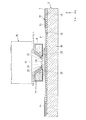
図2は、本実施形態に係る液浸部材4及び液体供給装置5の一例を示す図である。なお、図2を用いる説明においては、投影領域PR(終端光学素子11及び液浸部材4と対向する位置)に基板Pが配置される場合を例にして説明するが、上述のように、基板ステージ2(カバー部材T)、及び計測ステージ3(カバー部材S、計測部材C)を配置することもできる。
FIG. 2 is a diagram illustrating an example of the
図2に示すように、液浸部材4は、射出面10と対向する位置に配置される開口19と、開口19の周囲に配置される下面20とを有する。射出面10から射出された露光光ELは、開口19を通過して、基板Pに照射可能である。
As shown in FIG. 2, the
また、液浸部材4は、液体LQを供給可能な供給口21と、液体LQを回収可能な回収口22とを備えている。供給口21は、射出面10から射出される露光光ELの光路Kに液体LQを供給可能である。供給口21から供給された液体LQの少なくとも一部は、開口19を介して、射出面10及び下面18と対向する基板P(物体)上に供給される。供給口21は、射出面10から射出される露光光ELの光路Kの近傍において、その光路Kに面するように配置されている。
Further, the
供給口21は、流路23を介して、液体供給装置5と接続されている。液体供給装置5は、液体LQを送出可能である。流路23は、液浸部材4の内部に形成された供給流路21R、及びその供給流路21Rと液体供給装置5とを接続する供給管24で形成される流路24Rを含む。液体供給装置5から送出された液体LQは、流路23を介して供給口21に供給される。
The
回収口22は、射出面10及び下面18と対向する基板P(物体)上の液体LQの少なくとも一部を回収可能である。回収口22は、基板P(物体)が対向可能な液浸部材4の所定位置に配置されている。本実施形態において、回収口22は、下面20の周囲の少なくとも一部に配置されている。
The
本実施形態において、回収口22には、複数の孔(openingsあるいはpores)を含むプレート状の多孔部材25が配置される。本実施形態において、基板P(物体)上の液体LQの少なくとも一部は、多孔部材25の孔を介して回収される。なお、回収口22に、網目状に多数の小さい孔が形成された多孔部材であるメッシュフィルタが配置されてもよい。多孔部材25の下面26に基板P(物体)が対向可能である。下面20の周囲に下面26が配置される。本実施形態において、液浸部材4の下面18の少なくとも一部は、下面20及び多孔部材25の下面26を含む。
In the present embodiment, a plate-like
回収口22は、流路27を介して、液体回収装置6と接続されている。液体回収装置6は、回収口22を介して液体LQを吸引可能である。流路27は、液浸部材4の内部に形成された回収流路22R、及びその回収流路22Rと液体回収装置6とを接続する回収管28で形成される流路28Rを含む。回収口22(多孔部材25の孔)から回収された液体LQは、流路27を介して、液体回収装置6に回収される。
The
液体供給装置5は、流路23を介して、供給口21に液体LQを供給可能である。液体供給装置5は、供給口21を介して、露光光ELの光路Kの少なくとも一部に液体LQを供給可能である。射出面10と対向する位置に基板P(物体)が配置されている状態において、液体供給装置5は、供給口21を介して、射出面10と基板P(物体)の表面との間の露光光ELの光路Kに液体LQを供給可能である。
The
本実施形態においては、露光装置EXが液体供給装置5を有する。なお、液体供給装置5が、露光装置EXとは別の装置でもよい。換言すれば、液体供給装置5は、露光装置EXに対する外部の装置でもよい。液体供給装置5が露光装置EXに対する外部の装置である場合、その液体供給装置5は、流路23を介して供給口21に接続されることによって露光装置EXに使用される。
In the present embodiment, the exposure apparatus EX has a
液体供給装置5は、脱気処理された液体LQsに溶存する所定ガス濃度を高める処理を実行する液体処理装置31を備えている。液体処理装置31は、脱気処理された液体LQsに所定ガスGを溶解して、その液体LQsに溶存する所定ガス濃度を高める処理を実行可能である。
The
本実施形態において、所定ガスGは、酸素ガスである。なお、所定ガスGが、酸素ガスと、酸素ガスとは異なる種類のガス(例えば窒素ガス)とを含んでいてもよい。なお、所定ガスGが、炭酸ガス、水素ガス、及びオゾンガスの少なくとも一つを含んでもよい。また、所定ガスGが、不活性ガスを含んでもよい。 In the present embodiment, the predetermined gas G is oxygen gas. Note that the predetermined gas G may include oxygen gas and a different type of gas (for example, nitrogen gas) from the oxygen gas. The predetermined gas G may include at least one of carbon dioxide gas, hydrogen gas, and ozone gas. Further, the predetermined gas G may include an inert gas.
本実施形態において、液体供給装置5は、液体LQpの脱気処理を実行可能な脱気装置32を備えている。脱気処理は、液体LQpに含まれるガスを除去する処理である。脱気処理によって、少なくとも、液体LQpに含まれる所定ガスGが液体LQpから除去される。
In the present embodiment, the
脱気装置32は、例えば米国特許出願公開第2005/0219490号明細書等に開示されているような、液体に溶存するガス濃度を低減可能な膜脱気装置を含む。本実施形態において、脱気装置32は、液体LQpを供給可能な供給源SPLに接続される。本実施形態において、供給源SPLは、液体LQpとして、水(純水)を供給する。本実施形態において、脱気装置32は、供給源SPLから供給された液体LQpの脱気処理を実行する。本実施形態において、脱気装置32は、管33に形成された流路33Rを介して供給源SPLに接続される。供給源SPLからの液体LQpは、流路33Rを介して脱気装置32に供給される。脱気装置32は、流路33Rを介して供給源SPLから供給された液体LQpの脱気処理を実行する。脱気装置32は、脱気処理された液体LQsを送出可能である。
The
本実施形態において、液体処理装置31は、脱気装置32に接続される。本実施形態において、液体処理装置31は、脱気装置32で脱気処理された液体LQsに溶存する所定ガス濃度を高める処理を実行可能である。本実施形態において、液体処理装置31は、管34に形成された流路34Rを介して脱気装置32に接続される。脱気装置32からの液体LQsは、流路34Rを介して液体処理装置31に供給される。液体処理装置31は、流路34Rを介して脱気装置32から供給された液体LQsに対して、溶存する所定ガス濃度を高める処理を実行する。
In the present embodiment, the
本実施形態において、液体処理装置31は、ガス供給装置35に接続される。ガス供給装置35は、所定ガスGを送出可能である。本実施形態において、液体処理装置31は、管36に形成された流路36Rを介してガス供給装置35に接続される。ガス供給装置35からの所定ガスGは、流路36Rを介して液体処理装置31に供給される。液体処理装置31は、流路36Rを介してガス供給装置35から供給された所定ガスGを液体LQsに溶解して、液体LQsに溶存する所定ガス濃度を高める。
In the present embodiment, the
液体処理装置31は、所定ガス濃度が高められた液体LQhを送出可能である。液体処理装置31は、流路34R(脱気装置32)から供給された脱気処理後の液体LQsに溶存する所定ガス濃度よりも高い所定ガス濃度の液体LQhを送出可能である。液体処理装置31は、所定ガス濃度が高められた液体LQhを流路23に送出し、供給口21を介して露光光ELの光路の少なくとも一部に供給可能である。
The
また、液体処理装置31は、所定ガス濃度が高められていない液体を送出可能である。液体処理装置21は、流路34R(脱気装置32)から供給された脱気処理後の液体LQsに溶存する所定ガス濃度よりとほぼ同じ所定ガス濃度の液体を送出可能である。例えば、液体処理装置31は、脱気装置32から供給された脱気処理後の液体LQsに対する所定ガス濃度を高める処理を実行せずに、その所定ガス濃度が低減されている液体LQsを送出可能である。本実施形態において、所定ガス濃度が低減されている液体LQsが、基板Pの露光において供給される液体(露光液体)LQとして使用される。液体処理装置31は、所定ガス濃度が高められていない(所定ガス濃度が低減されている)液体LQsを流路23に送出し、供給口21を介して露光光ELの光路の少なくとも一部に供給可能である。
Moreover, the
なお、液体処理装置31が、流路34R(脱気装置32)から供給された脱気処理後の液体LQsに溶存する所定ガス濃度よりも低い所定ガス濃度の液体LQssを送出してもよい。例えば、液体処理装置31が、流路34R(脱気装置32)から供給された液体LQsの脱気処理を実行して液体LQssを生成してもよい。液体処理装置31は、所定ガス濃度が低減された液体LQssを流路23に送出し、供給口21を介して露光光ELの光路の少なくとも一部に供給可能である。なお、そのLQssが、基板Pの露光において供給される液体(露光液体)LQとして使用されてもよい。
Note that the
以下の説明において、所定ガス濃度が高められた液体LQhを供給口21(光路K)に供給する動作を適宜、第1モード、と称する。また、所定ガス濃度が低減されている液体LQs(LQ)を供給口21(光路K)に供給する動作を適宜、第2モード、と称する。 In the following description, the operation of supplying the liquid LQh having a predetermined gas concentration increased to the supply port 21 (optical path K) is appropriately referred to as a first mode. In addition, the operation of supplying the liquid LQs (LQ) having a predetermined gas concentration reduced to the supply port 21 (optical path K) is appropriately referred to as a second mode.
本実施形態において、第1モードは、液体供給装置5(液体処理装置31)が液体LQsに溶存する所定ガス濃度を高める処理を実行することを含む。第2モードは、液体供給装置5(液体処理装置31)が液体LQsに溶存する所定ガス濃度を高める処理を実行しないことを含む。換言すれば、第2モードは、液体供給装置5(液体処理装置31)が所定ガス濃度を高める処理を停止することを含む。第1モードにおいては、所定ガス濃度を高める処理が実行された液体LQhが供給口21から供給される。第2モードにおいては、液体処理装置31による所定ガス濃度を高める処理が停止され、所定ガス濃度を高める処理が実行されない液体LQ(LQs)が供給口21から供給される。
In the present embodiment, the first mode includes the liquid supply device 5 (liquid processing device 31) executing a process for increasing the concentration of a predetermined gas dissolved in the liquid LQs. The second mode includes that the liquid supply apparatus 5 (liquid processing apparatus 31) does not execute a process for increasing the predetermined gas concentration dissolved in the liquid LQs. In other words, the second mode includes the liquid supply device 5 (liquid processing device 31) stopping the process of increasing the predetermined gas concentration. In the first mode, the liquid LQh that has been processed to increase the predetermined gas concentration is supplied from the
図3は、液体処理装置31の一例を示す図である。本実施形態において、液体処理装置31は、気体透過膜43を用いて液体にガスを溶解させる膜溶解装置40を有する。
FIG. 3 is a diagram illustrating an example of the
膜溶解装置40は、空間41を形成する容器42と、空間41に配置された気体透過膜43とを有する。気体透過膜43は、気体を透過し、液体を透過しない膜である。気体透過膜43は、空間41を第1空間(液体室)41Aと第2空間(液体室)41Bとに分けるように配置される。
The
流路34R(脱気装置32)からの液体LQsは、液体室41Aに供給される。流路36R(ガス供給装置35)からの所定ガスGは、気体室41Bに供給される。気体室41Bの所定ガスGの少なくとも一部は、気体透過膜43を透過して、液体室41Aに移動可能である。これにより、液体室41Aの液体LQsに所定ガスGが溶解し、溶存する所定ガス濃度が高められた液体LQhが生成される。液体処理装置31は、気泡を含まず、所定ガス濃度が高められた液体LQhを送出可能である。
The liquid LQs from the
なお、液体に気体を溶解可能な溶解装置の一例が、例えば特開2009−219997号公報に開示されている。 An example of a dissolution apparatus capable of dissolving a gas in a liquid is disclosed in, for example, Japanese Patent Application Laid-Open No. 2009-219997.
本実施形態において、液体処理装置31は、流路34Rと流路24R(23)とを接続可能な流路44Rを有する管44と、流路44Rの一端に配置される流路切替機構45と、流路44Rの他端に配置される流路切替機構46とを有する。流路切替機構45、46は、例えばバルブ機構を含む。流路44Rの一端は、流路切替機構45を介して流路34Rに接続され、流路44Rの他端は、流路切替機構46を介して流路24R(23)に接続される。
In the present embodiment, the
本実施形態において、制御装置7は、流路切替機構45、46を制御して、第1モード及び第2モードの少なくとも一方を実行可能である。
In the present embodiment, the control device 7 can control the flow
制御装置7は、第1モードを実行するとき、脱気装置32からの液体LQsが膜溶解装置40に供給され、流路44Rに供給されないように、流路切替機構45を制御する。膜溶解装置40は、供給された液体LQsに所定ガスGを溶解し、溶存する所定ガス濃度が高められた液体LQhを生成する。膜溶解装置40によって生成された液体LQhは、流路23に送出される。制御装置7は、膜溶解装置40から送出された液体LQhが流路23を介して供給口21に供給され、流路44Rに供給されないように、流路切替機構46を制御する。
When executing the first mode, the control device 7 controls the flow
制御装置7は、第2モードを実行するとき、脱気装置32からの液体LQsが流路44Rに供給され、膜溶解装置40に供給されないように、流路切替機構45を制御する。流路44Rを流れた液体LQsは、流路切替機構46を介して流路23に流入する。制御装置7は、流路44Rからの液体LQsが流路23を介して供給口21に供給されるように、流路切替機構46を制御する。すなわち、制御装置7は、第2モードを実行するとき、膜溶解装置40による所定ガス濃度を高める処理が実行されないように、流路切替機構45、46を制御する。なお、第2モードを実行するとき、膜溶解装置40による所定ガス濃度を高める処理が停止されてもよい。
When executing the second mode, the control device 7 controls the flow
図2に示すように、本実施形態において、液体供給装置5は、供給口21に供給する単位時間当たりの液体LQ(LQh)の量(液体供給量)を調整可能な供給量調整装置37を備えている。供給量調整装置37は、例えばマスフローコントローラを含み、単位時間当たりの液体供給量を調整可能である。制御装置7は、供給量調整装置37を制御して、供給口21を介して光路Kに供給される単位時間当たりの液体LQ(LQh)の供給量を調整可能である。
As shown in FIG. 2, in this embodiment, the
なお、液体供給装置5が、液体LQ(LQh、LQs、LQp)中の異物を除去可能なフィルタユニット、及び供給口21に供給する液体LQ(LQh)の温度を調整可能な温度調整装置を有してもよい。
The
本実施形態において、制御装置7は、液体処理装置31、脱気装置32、及びガス供給装置35の少なくとも一つを制御して、液体処理装置31から送出される液体に溶存する所定ガス濃度を調整可能である。制御装置7は、例えば液体処理装置31の液体室41A及び気体室41Bの少なくとも一方の圧力を調整したり、脱気装置32から液体処理装置31に供給される液体LQsの量を調整したり、脱気装置32の処理能力を調整して脱気装置32から送出される液体LQsに溶存するガス濃度を調整したり、ガス供給装置35から液体処理装置31に供給される所定ガスGの量を調整したりすることによって、液体処理装置31から送出される液体に溶存する所定ガス濃度を調整可能である。
In the present embodiment, the control device 7 controls at least one of the
第1モードにおいては、液体処理装置31によって処理された液体LQhに溶存する所定ガス濃度は、流路34R(脱気装置32)から液体処理装置31に供給される液体LQsに溶存する所定ガス濃度よりも高い。第2モードにおいては、液体処理装置31から送出される液体LQ(LQs)に溶存する所定ガス濃度は、流路34R(脱気装置32)から液体処理装置31に供給される液体LQsに溶存する所定ガス濃度とほぼ等しい。
In the first mode, the predetermined gas concentration dissolved in the liquid LQh processed by the
本実施形態において、流路34Rを介して液体処理装置31に供給される液体LQsに溶存するガス濃度は、例えば10〜100ppb程度でもよい。また、第1モードにおいて、液体処理装置31から流路24Rに送出される液体LQhに溶存する所定ガス濃度が、300〜500ppb程度でもよい。また、第1モードにおいて、流路34Rを介して液体処理装置31に供給される液体LQsに溶存するガス濃度に対して、液体処理装置31から流路24Rに送出される液体LQhに溶存する所定ガス濃度が、例えば3倍〜50倍でもよい。また、第1モードにおいて、流路34Rを介して液体処理装置31に供給される液体LQsに溶存するガス濃度に対して、供給口21から光路Kに供給される液体LQhに溶存する所定ガス濃度が3倍〜50倍になるように調整されてもよい。また、液体処理装置31から流路24Rに送出される液体LQhに溶存する所定ガス濃度に対して、供給口21から光路Kに供給される液体LQhに溶存する所定ガス濃度が所定倍になるように調整されてもよい。
In the present embodiment, the gas concentration dissolved in the liquid LQs supplied to the
なお、本実施形態において、液体供給装置5が、供給源SPLを備えていてもよい。なお、供給源SPLが、露光装置EXが設置される工場の設備でもよい。また、液体供給装置5が露光装置EXに対する外部の装置である場合において、露光装置EXが供給源SPLを備えていてもよい。
In the present embodiment, the
なお、本実施形態において、脱気装置32が、液体供給装置5とは別の装置でもよい。換言すれば、脱気装置32は、液体供給装置5に対する外部の装置でもよい。また、脱気装置32が、露光装置EXとは別の装置でもよい。また、液体供給装置5が露光装置EXに対する外部の装置である場合において、露光装置EXが脱気装置32を備えていてもよい。脱気装置32が液体供給装置5に対する外部の装置であっても、液体供給装置5は、脱気処理された液体LQsに溶存する所定ガス濃度を高める処理を実行可能である。
In the present embodiment, the
なお、本実施形態において、液体供給装置5がガス供給装置35を備えてもよい。あるいは、ガス供給装置35が、液体供給装置5とは別の装置でもよい。換言すれば、ガス供給装置35は、液体供給装置5に対する外部の装置でもよい。また、ガス供給装置35が、露光装置EXとは別の装置でもよい。また、液体供給装置5が露光装置EXに対する外部の装置である場合において、露光装置EXがガス供給装置35を備えていてもよい。ガス供給装置35が液体供給装置5に対する外部の装置であっても、液体供給装置5は、脱気処理された液体LQsに溶存する所定ガス濃度を高める処理を実行可能である。
In the present embodiment, the
液体回収装置6は、回収口22からの液体LQ(LQh)を回収可能である。液体回収装置6は、回収口22を真空システムに接続可能である。なお、液体回収装置6が、液体LQ(LQh)を吸引可能な真空システムを備えていてもよい。液体回収装置6は、回収口22から回収される単位時間当たりの液体回収量を調整可能である。制御装置7は、液体回収装置6を制御して、回収口22を介して基板P上から回収される単位時間当たりの液体LQの回収量を調整可能である。
The liquid recovery device 6 can recover the liquid LQ (LQh) from the
なお、回収口22から多孔部材25を介して実質的に液体LQ(LQh)のみが回収されてもよい。また、回収口22から多孔部材25を介して液体LQ(LQh)が液浸空間LSの周囲のガスとともに回収されてもよい。なお、回収口22に多孔部材25が配置されなくてもよい。
Note that substantially only the liquid LQ (LQh) may be recovered from the
なお、液浸部材4として、例えば米国特許出願公開第2007/0132976号明細書、欧州特許出願公開第1768170号明細書に開示されているような液浸部材(ノズル部材)を用いることができる。
In addition, as the
本実施形態において、制御装置7は、供給口21から基板P(物体)上に液体LQ(LQh)を供給し、その液体LQ(LQh)の供給と並行して、回収口22から基板P(物体)上の液体LQ(LQh)を回収することによって、一方側の終端光学素子12及び液浸部材6と、他方側の基板P(物体)との間に液体LQ(LQh)で液浸空間LSを形成可能である。
In the present embodiment, the controller 7 supplies the liquid LQ (LQh) from the
図4は、終端光学素子11及び液浸部材4と基板Pとの間に液体LQで液浸空間LSが形成されている状態の一例を示す図である。図4に示すように、基板Pは保持部13に保持され、カバー部材Tは保持部15に保持される。カバー部材Tは、保持部13に保持された基板Pの周囲に配置される。基板ステージ2が移動することによって、保持部13に保持された基板P、及び保持部15に保持されたカバー部材Tは、投影領域PRに移動可能である。
FIG. 4 is a diagram illustrating an example of a state in which the immersion space LS is formed with the liquid LQ between the terminal
本実施形態において、保持部13は、基板Pの表面(上面)とXY平面とがほぼ平行となるように、基板Pを保持する。保持部15は、カバー部材Tの上面TfとXY平面とがほぼ平行となるように、カバー部材Tを保持する。本実施形態において、保持部13に保持された基板Pの表面と保持部15に保持されたカバー部材Tの上面Tfとは、ほぼ同一平面内に配置される(ほぼ面一である)。なお、Z軸方向に関する基板Pの表面の位置とカバー部材Tの上面Tfとの位置とが異なってもよい。また、カバー部材Tの上面Tfの少なくとも一部が、基板Pの表面(XY平面)に対して傾斜していてもよい。また、カバー部材Tの上面Tfの少なくとも一部が曲面でもよい。
In the present embodiment, the holding
本実施形態において、カバー部材Tの上面Tfは、液体LQ(LQh)に対して撥液性の膜Frの表面を含む。液体LQに対する上面Tfの接触角は、例えば90度以上である。本実施形態において、液体LQに対する上面Tfの接触角は、100度以上である。 In the present embodiment, the upper surface Tf of the cover member T includes the surface of the film Fr that is liquid repellent with respect to the liquid LQ (LQh). The contact angle of the upper surface Tf with respect to the liquid LQ is, for example, 90 degrees or more. In the present embodiment, the contact angle of the upper surface Tf with respect to the liquid LQ is 100 degrees or more.
図1に示すように、保持部14は、計測部材Cの表面(上面)CfとXY平面とがほぼ平行となるように、計測部材Cを保持する。保持部16は、カバー部材Sの上面SfとXY平面とがほぼ平行となるように、カバー部材Sを保持する。本実施形態において、保持部14に保持された計測部材Cの上面Cfと保持部16に保持されたカバー部材Sの上面Sfとは、ほぼ同一平面内に配置される(ほぼ面一である)。なお、Z軸方向に関する計測部材Cの上面Cfの位置とカバー部材Sの上面Sfとの位置とが異なってもよい。また、カバー部材Sの上面Sfの少なくとも一部が、計測部材Cの上面Cf(XY平面)に対して傾斜していてもよい。また、カバー部材Sの上面Sfの少なくとも一部が曲面でもよい。
As illustrated in FIG. 1, the holding
本実施形態において、カバー部材Sの上面Sfは、液体LQに対して撥液性の膜Frの表面を含む。液体LQに対する上面Sfの接触角は、例えば90度以上である。本実施形態において、液体LQに対する上面Sfの接触角は、100度以上である。 In the present embodiment, the upper surface Sf of the cover member S includes the surface of the film Fr that is liquid repellent with respect to the liquid LQ. The contact angle of the upper surface Sf with respect to the liquid LQ is, for example, 90 degrees or more. In the present embodiment, the contact angle of the upper surface Sf with respect to the liquid LQ is 100 degrees or more.
また、本実施形態において、計測部材Cの上面Cfは、液体LQに対して撥液性の膜Frの表面を含む。液体LQに対する上面Cfの接触角は、例えば90度以上である。本実施形態において、液体LQに対する上面Cfの接触角は、100度以上である。 In the present embodiment, the upper surface Cf of the measurement member C includes the surface of the film Fr that is liquid repellent with respect to the liquid LQ. The contact angle of the upper surface Cf with respect to the liquid LQ is, for example, 90 degrees or more. In the present embodiment, the contact angle of the upper surface Cf with respect to the liquid LQ is 100 degrees or more.
本実施形態において、膜Frを形成する材料は、フッ素を含むフッ素系材料である。本実施形態において、膜Frは、PFA(Tetra fluoro ethylene-perfluoro alkylvinyl ether copolymer)の膜である。なお、膜Frが、PTFE(Poly tetra fluoro ethylene)、PEEK(polyetheretherketone)、テフロン(登録商標)等の膜でもよい。また、膜Frが、旭硝子社製「サイトップ」、あるいは3M社製「Novec EGC」でもよい。また、上面Tfを形成する膜Frと上面Sfを形成する膜Frとが、異なる種類の材料で形成されてもよい。また、上面Cfを形成する膜Frと上面Sfを形成する膜Frとが異なる種類の材料で形成されてもよい。 In the present embodiment, the material forming the film Fr is a fluorine-based material containing fluorine. In the present embodiment, the film Fr is a film of PFA (Tetrafluoroethylene-perfluoroalkylvinylether copolymer). The film Fr may be a film of PTFE (Poly tetrafluoroethylene), PEEK (polyetheretherketone), Teflon (registered trademark), or the like. The membrane Fr may be “Cytop” manufactured by Asahi Glass Co., or “Novec EGC” manufactured by 3M. Further, the film Fr that forms the upper surface Tf and the film Fr that forms the upper surface Sf may be formed of different types of materials. Further, the film Fr that forms the upper surface Cf and the film Fr that forms the upper surface Sf may be formed of different types of materials.
本実施形態において、射出面10及び下面18と対向可能な基板ステージ2の上面は、カバー部材Tの上面Tfを含む。射出面10及び下面18と対向可能な計測ステージ3の上面は、カバー部材Sの上面Sf及び計測部材Cの上面Cfの少なくとも一方を含む。以下の説明において、カバー部材Tの上面Tfを適宜、基板ステージ2の上面、と称し、カバー部材Sの上面Sf及び計測部材Cの上面Cfを合わせて適宜、計測ステージ3の上面、と称する。
In the present embodiment, the upper surface of the
次に、上述の構成を有する露光装置EXの動作の一例について、図5のフローチャートを参照して説明する。 Next, an example of the operation of the exposure apparatus EX having the above-described configuration will be described with reference to the flowchart of FIG.
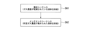
図5に示すように、本実施形態においては、終端光学素子11の射出面10から射出される露光光ELで液体LQを介して基板Pを露光する露光処理を含む露光シーケンス(ステップSA1)と、液体LQhを用いて露光装置EXの部材をメンテナンスするメンテナンスシーケンス(ステップSA2)とが実行される。
As shown in FIG. 5, in the present embodiment, an exposure sequence (step SA1) including an exposure process that exposes the substrate P through the liquid LQ with the exposure light EL emitted from the
まず、露光シーケンスについて説明する。露光シーケンスは、基板Pの交換処理、計測ステージ3を用いる計測処理、及び液体LQを介して基板Pを露光する露光処理を含む。露光シーケンスの少なくとも一部において、制御装置7は、脱気処理されて溶存するガス濃度が低減されている液体LQ(LQs)が供給口21から光路Kに対して供給されるように、液体供給装置5を制御する。すなわち、露光シーケンスの少なくとも一部において、制御装置7は、第2モードを実行する。
First, the exposure sequence will be described. The exposure sequence includes a substrate P exchange process, a measurement process using the
制御装置7は、基板搬送装置(不図示)を用いて、基板Pの交換処理を実行する。制御装置7は、露光前の基板Pを保持部13に搬入(ロード)する。なお、保持部13に露光後の基板Pが保持されている場合、その基板Pが保持部13から搬出(アンロード)された後、露光前の基板Pが保持部13に搬入(ロード)される。
The control device 7 executes a substrate P replacement process using a substrate transfer device (not shown). The control device 7 loads (loads) the substrate P before exposure into the holding
また、制御装置7は、計測ステージ3(計測部材C、計測器)を用いて、所定の計測処理を実行する。露光前の基板Pが保持部13にロードされ、計測ステージ3を用いる計測処理が終了した後、制御装置7は、基板ステージ2を投影領域PRに移動して、終端光学素子11及び液浸部材4と基板P(基板ステージ2)との間に液体LQで液浸空間LSを形成する。
Moreover, the control apparatus 7 performs a predetermined | prescribed measurement process using the measurement stage 3 (measurement member C, measuring device). After the substrate P before exposure is loaded onto the holding
制御装置7は、基板Pの露光を開始する。本実施形態の露光装置EXは、マスクMと基板Pとを所定の走査方向に同期移動しつつ、マスクMのパターンの像を基板Pに投影する走査型露光装置(所謂スキャニングステッパ)である。基板Pの露光において、制御装置7は、マスクステージ1及び基板ステージ2を制御して、マスクM及び基板Pを、XY平面内の所定の走査方向に移動する。本実施形態においては、基板Pの走査方向(同期移動方向)をY軸方向とし、マスクMの走査方向(同期移動方向)もY軸方向とする。
The control device 7 starts exposure of the substrate P. The exposure apparatus EX of the present embodiment is a scanning exposure apparatus (so-called scanning stepper) that projects an image of the pattern of the mask M onto the substrate P while synchronously moving the mask M and the substrate P in a predetermined scanning direction. In the exposure of the substrate P, the control device 7 controls the mask stage 1 and the
制御装置7は、基板P(ショット領域)を投影光学系PLの投影領域PRに対してY軸方向に移動するとともに、その基板PのY軸方向への移動と同期して、照明系ILの照明領域IRに対してマスクMをY軸方向に移動しつつ、投影光学系PLと基板P上の液浸空間LSの液体LQとを介して基板Pに露光光ELを照射する。これにより、マスクMのパターンの像が基板Pに投影され、その基板Pが射出面10から射出された露光光ELで露光される。基板P上に複数のショット領域が設けられている場合、制御装置7は、それら複数のショット領域を、液体LQを介して順次露光する。
The control device 7 moves the substrate P (shot region) in the Y-axis direction with respect to the projection region PR of the projection optical system PL, and in synchronization with the movement of the substrate P in the Y-axis direction, While moving the mask M in the Y-axis direction with respect to the illumination region IR, the exposure light EL is irradiated onto the substrate P through the projection optical system PL and the liquid LQ in the immersion space LS on the substrate P. Thereby, an image of the pattern of the mask M is projected onto the substrate P, and the substrate P is exposed with the exposure light EL emitted from the
本実施形態において、液体供給装置5は、少なくとも基板Pの表面に射出面10からの露光光ELが照射されているときに、所定ガス濃度を高める処理が実行されない液体LQ(LQs)を、射出面10と基板Pの表面との間の光路Kに供給する。例えば、液体供給装置5は、基板Pの表面に射出面10からの露光光ELが照射されているときに、液体処理装置31による所定ガス濃度を高める処理を停止する。
In the present embodiment, the
基板Pの露光が終了した後、制御装置7は、その露光後の基板Pを保持した基板ステージ2を基板交換位置に移動する。露光後の基板Pは、基板ステージ2からアンロードされ、露光前の基板Pが基板ステージ2にロードされる。以下、制御装置7は、上述の処理を繰り返して、複数の基板Pを順次露光する。
After the exposure of the substrate P is completed, the control device 7 moves the
次に、メンテナンスシーケンスについて説明する。 Next, the maintenance sequence will be described.
露光シーケンスにおいて、基板Pから発生(溶出)した物質(例えば感光材等の有機物)が、異物(汚染物、パーティクル)として液浸空間LSの液体LQ中に混入する可能性がある。また、基板Pから発生する物質のみならず、例えば空中を浮遊する異物が、液浸空間LSの液体LQに混入する可能性もある。液浸空間LSの液体LQ中に異物が混入すると、その液体LQに接触する基板ステージ2の上面(カバー部材Tの上面Tf)、計測ステージ3の上面(カバー部材Sの上面Sf、計測部材Cの上面Cf)、及び液浸部材4の下面18の少なくとも一部に異物が付着する可能性がある。
In the exposure sequence, a substance (e.g., an organic substance such as a photosensitive material) generated (eluted) from the substrate P may be mixed into the liquid LQ in the immersion space LS as a foreign substance (contaminant, particle). Further, not only substances generated from the substrate P but also foreign substances floating in the air may be mixed into the liquid LQ in the immersion space LS. When foreign matter enters the liquid LQ in the immersion space LS, the upper surface of the substrate stage 2 (the upper surface Tf of the cover member T) that contacts the liquid LQ, the upper surface of the measurement stage 3 (the upper surface Sf of the cover member S, the measurement member C). There is a possibility that foreign matter may adhere to at least a part of the upper surface Cf) and the
そこで、本実施形態においては、制御装置7は、非露光シーケンス時に、基板ステージ2の上面、及び計測ステージ3の上面の少なくとも一部のメンテナンス処理を実行する。メンテナンス処理は、基板ステージ2の上面、及び計測ステージ3の上面の少なくとも一部をクリーニングする処理を含む。
Therefore, in the present embodiment, the control device 7 performs maintenance processing on at least a part of the upper surface of the
以下、計測ステージ3の上面をメンテナンスする場合を例にして説明する。本実施形態において、メンテナンス処理は、液体LQhを介して計測ステージ3の上面に射出面10からの露光光ELを照射する処理を含む。計測ステージ3の上面に露光光(紫外光)ELが照射されることによって、その計測ステージ3の上面が光洗浄される。
Hereinafter, the case where the upper surface of the
図6は、計測ステージ3の上面に射出面10からの露光光ELが照射されている状態の一例を示す図である。本実施形態において、液体供給装置5は、露光装置EXが有する計測ステージ3の上面に射出面10からの露光光ELが照射されるときに、所定ガス濃度が高められた液体LQhを射出面10と計測ステージ3の上面との間の光路Kに供給する。すなわち、制御装置7は、メンテナンスシーケンスの少なくとも一部において、第1モードを実行する。
FIG. 6 is a diagram illustrating an example of a state in which the upper surface of the
液体供給装置5は、液体処理装置31を用いて、脱気処理された液体LQsに溶存する所定ガス濃度を高める処理を実行して液体LQhを生成し、その所定ガス濃度が高められた液体LQhを、射出面10と計測ステージ3の上面との間の露光光ELの光路Kに供給する。
The
上述のように、本実施形態において、計測ステージ3の上面は、液体LQに対して撥液性の膜Frの表面を含む。本発明者の知見によれば、その膜Frとガス濃度が低い液体(LQs)とを接触させた状態で、その膜Frに紫外光を照射すると、その膜Frの撥液性が著しく低下する可能性が高いことが分かった。例えば、液体に溶存する酸素濃度が低いと、膜Frの撥液性が著しく低下する可能性がある。
As described above, in the present embodiment, the upper surface of the
本実施形態においては、局所液浸方式を採用しており、終端光学素子11及び液浸部材4との間で液浸空間LSを形成する物体(基板ステージ2,及び計測ステージ3等)の表面(上面)は、液体LQに対して撥液性であることが望ましい。液体LQに対する物体の表面の撥液性が低下すると、終端光学素子11及び液浸部材4と物体との間に液体LQを良好に保持することが困難となり、液浸空間LSの液体LQが流出したり、物体の表面に液体LQが残留したりする可能性がある。また、本実施形態においては、物体は、終端光学素子11及び液浸部材4に対して移動可能であり、その物体の表面の撥液性が低下すると、その物体の移動に伴って、液浸空間LSの液体LQが流出したり、物体の表面に残留したりする可能性が高くなる。また、流出あるいは残留する液体LQによって気化熱が発生し、物体が熱変形したり、基板Pが熱変形したり、物体の周囲の環境(温度、湿度等)が変動したりしてしまう可能性がある。その結果、計測不良及び露光不良が発生する可能性がある。
In this embodiment, a local liquid immersion method is adopted, and the surface of an object (
本実施形態によれば、計測ステージ3の上面に射出面10からの露光光(紫外光)ELが照射されるときに射出面10と計測ステージ3の上面との間の光路Kに供給される液体LQhに溶存する所定ガス濃度が、基板Pの表面に射出面10からの露光光ELが照射されるときに射出面10と基板Pの表面との間の光路Kに供給される液体LQに溶存する所定ガス濃度よりも高いので、液体LQに対する計測ステージ3の上面の撥液性が低下することが抑制される。したがって、液浸空間LSの液体LQが流出したり、計測ステージ3の上面に液体LQが残留したりすることを抑制することができる。
According to the present embodiment, when the exposure light (ultraviolet light) EL from the
また、液体LQhと計測ステージ3の上面とを接触させた状態で、その計測ステージ3の上面に露光光(紫外光)ELを照射することによって、その計測ステージ3の上面を良好に光洗浄することができる。
In addition, with the liquid LQh and the upper surface of the
なお、図6は、計測部材Cの上面Cfに露光光ELを照射して上面Cfを光洗浄している状態を示しているが、もちろん、液体LQhとカバー部材Sの上面Sfとを接触させた状態で、カバー部材Sの上面Sfに露光光ELを照射して上面Sfを光洗浄してもよい。 FIG. 6 shows a state in which the upper surface Cf of the measuring member C is irradiated with the exposure light EL and the upper surface Cf is optically washed. Of course, the liquid LQh and the upper surface Sf of the cover member S are brought into contact with each other. In this state, the upper surface Sf of the cover member S may be irradiated with the exposure light EL to be optically cleaned.
また、液体LQhと基板ステージ2の上面(カバー部材Tの上面Tf)とを接触させた状態で、基板ステージ2の上面に露光光ELを照射して基板ステージ2の上面を光洗浄してもよい。これにより、液体LQに対する基板ステージ2の上面の撥液性の低下を抑制しつつ、その基板ステージ2の上面を良好に光洗浄できる。
Further, even when the liquid LQh and the upper surface of the substrate stage 2 (the upper surface Tf of the cover member T) are in contact with each other, the upper surface of the
なお、基板ステージ2の上面のメンテナンス時(光洗浄時)において、保持部13にダミー基板を保持した状態で、基板ステージ2の上面に露光光ELを照射してもよい。ダミー基板は、デバイス製造用の基板Pよりも異物を放出し難く、基板Pとほぼ同じ外形を有する基板である。保持部13は、ダミー基板をリリース可能に保持できる。保持部13にダミー基板を保持した状態で、基板ステージ2の上面をメンテナンスすることによって、例えば液体LQhが保持部13に付着することを抑制でき、液体LQhの液浸空間LSを良好に形成できる。
Note that, during maintenance of the upper surface of the substrate stage 2 (during light cleaning), the exposure light EL may be irradiated on the upper surface of the
メンテナンスシーケンスが終了した後、そのメンテナンスされた露光装置EXを用いて露光シーケンスが実行されてもよい。 After the maintenance sequence is completed, the exposure sequence may be executed using the maintained exposure apparatus EX.
以上説明したように、本実施形態によれば、所定ガス濃度が高められた液体LQhを介して物体の上面(基板ステージ2の上面、計測ステージ3の上面等)に露光光ELを照射するようにしたので、液体LQに対する物体の上面の撥液性の低下を抑制することができる。また、露光光ELの照射により、物体の上面を光洗浄することができる。したがって、例えば露光シーケンスにおいて、終端光学素子11及び液浸部材4と物体と間の空間に液体LQを良好に保持することができ、液体LQの流出、残留等を抑制することができる。また、液浸空間LSの液体LQの質(水質)を維持することができる。そのため、露光不良の発生、不良デバイスの発生を抑制することができる。
As described above, according to the present embodiment, the exposure light EL is irradiated onto the upper surface of the object (the upper surface of the
本実施形態においては、液体LQpの脱気処理を実行し、液体LQpに溶存するガスを除去して液体LQsを生成した後、その液体LQsに所定ガスGを溶解させる。これにより、所定ガスG以外のガスが液体LQhに溶存することを抑制しつつ、液体LQhにおける所定ガスGの濃度を精度良く調整できる。例えば、液体LQに対する物体の表面の撥液性の低下を抑制しつつ光洗浄を実行する場合において、液体LQhに溶存させる所定ガスGとして酸素ガスが好ましい場合、その酸素ガスのみを液体LQhに溶存させ、酸素ガス以外のガスが液体LQh中に存在することを抑制できる。また、本実施形態によれば、溶存するガスが低減された液体LQsに所定ガスGを溶解させるので、液体LQhに溶存する所定ガス濃度を精度良く調整できる。 In the present embodiment, the liquid LQp is degassed, the gas dissolved in the liquid LQp is removed to generate the liquid LQs, and then the predetermined gas G is dissolved in the liquid LQs. Thereby, the concentration of the predetermined gas G in the liquid LQh can be accurately adjusted while suppressing the gas other than the predetermined gas G from being dissolved in the liquid LQh. For example, when performing optical cleaning while suppressing a decrease in liquid repellency of the surface of the object with respect to the liquid LQ, when oxygen gas is preferable as the predetermined gas G to be dissolved in the liquid LQh, only the oxygen gas is dissolved in the liquid LQh. Therefore, it is possible to suppress the presence of gas other than oxygen gas in the liquid LQh. Moreover, according to this embodiment, since the predetermined gas G is dissolved in the liquid LQs in which the dissolved gas is reduced, the concentration of the predetermined gas dissolved in the liquid LQh can be accurately adjusted.
なお、所定ガスGは、液体LQhに求められる機能(性能)に応じて適宜選択可能である。例えば、物体の帯電を抑制したい場合、あるいは物体に帯電している電気(静電気)を除去したい場合、所定ガスGとして炭酸ガスを用いてもよい。炭酸ガスが溶存する液体LQhを物体上に供給することによって、その物体の帯電等を抑制することができる。 The predetermined gas G can be appropriately selected according to the function (performance) required for the liquid LQh. For example, when it is desired to suppress charging of an object, or when it is desired to remove electricity (static electricity) charged on the object, carbon dioxide gas may be used as the predetermined gas G. By supplying the liquid LQh in which the carbon dioxide gas is dissolved onto the object, charging or the like of the object can be suppressed.
また、本実施形態においては、基板Pの表面に射出面10からの露光光ELが照射されるときに光路Kに供給される液体LQに溶存する所定ガス濃度は、物体の上面(基板ステージ2の上面、計測ステージ3の上面等)に露光光ELが照射されるときに光路Kに供給される液体LQhに溶存する所定ガス濃度よりも低い。したがって、例えば基板Pの露光において光路Kを満たす液体LQに気泡が発生することを抑制でき、露光不良の発生を抑制できる。
In the present embodiment, the predetermined gas concentration dissolved in the liquid LQ supplied to the optical path K when the surface of the substrate P is irradiated with the exposure light EL from the
なお、本実施形態においては、基板ステージ2の上面及び計測ステージ3の上面の少なくとも一方のメンテナンスにおいて、所定ガス濃度が高められた液体LQhを供給することとしたが、露光シーケンスの少なくとも一部において液体LQhを供給してもよい。例えば計測ステージ3を用いる計測処理において光路Kに液体LQhを供給してもよい。例えば、図6に示したように、終端光学素子11及び液浸部材4と計測部材Cとの間に、所定ガス濃度が高められた液体LQhで液浸空間LSを形成し、その液体LQhの液浸空間LSが形成されている状態で、射出面10からの露光光ELを計測部材Cに照射してもよい。計測部材Cに照射された露光光ELは、その計測部材Cを介して、光センサ50に受光される。これにより、液体LQに対する計測部材Cの上面Cfの撥液性の低下を抑制することができる。また、計測部材Cを用いる計測処理と並行して、計測部材Cの光洗浄を実行することができる。
In the present embodiment, the liquid LQh having a predetermined gas concentration is supplied in the maintenance of at least one of the upper surface of the
<第2実施形態>
次に、第2実施形態について説明する。以下の説明において、上述の実施形態と同一の構成部分については同一の符号を付し、その説明を簡略若しくは省略する。
Second Embodiment
Next, a second embodiment will be described. In the following description, the same components as those in the above-described embodiment are denoted by the same reference numerals, and the description thereof is simplified or omitted.
図7は、第2実施形態に係る露光装置EXの動作の一例を示すフローチャートである。図7に示すように、本実施形態において、終端光学素子11の射出面10から射出される露光光ELで液体LQを介して基板Pを露光する露光処理を含む露光シーケンス(ステップSB1)と、液体LQを用いて露光装置EXの部材をメンテナンスするメンテナンスシーケンス(ステップSB2)とが実行される。
FIG. 7 is a flowchart showing an example of the operation of the exposure apparatus EX according to the second embodiment. As shown in FIG. 7, in this embodiment, an exposure sequence (step SB1) including an exposure process for exposing the substrate P through the liquid LQ with the exposure light EL emitted from the
本実施形態においては、露光シーケンスのうち、少なくとも、基板Pの表面に射出面10からの露光光ELが照射されるときに、制御装置7は、射出面10と基板Pの表面との間の露光光ELの光路Kに、供給口21から単位時間当たり第1供給量で液体LQを供給する。一方、メンテナンスシーケンスにおいて、物体の上面(基板ステージ2の上面、計測ステージ3の上面等)に射出面10からの露光光ELが照射されるときに、制御装置7は、射出面10と物体の上面との間の露光光ELの光路Kに、供給口21から単位時間当たり第1供給量よりも少ない第2供給量で液体LQを供給する。
In the present embodiment, at least when the exposure light EL from the
本実施形態において、メンテナンスシーケンスにおいて供給口21から第2供給量で供給される液体LQは、所定ガス濃度が高められた液体LQhでもよいし、所定ガス濃度を高める処理が実行されない液体LQsでもよい。以下の説明においては、一例として、メンテナンスシーケンスにおいて供給口21から第2供給量で供給される液体LQが、所定ガス濃度が低減されている脱気処理後の液体LQsである場合を例にして説明する。
In the present embodiment, the liquid LQ supplied at the second supply amount from the
図8は、計測ステージ3の上面をメンテナンス(光洗浄)するために、終端光学素子11及び液浸部材4と計測ステージ3との間に、供給口21から供給された液体LQで液浸空間LSが形成されている状の一例を示す図である。
FIG. 8 shows an immersion space with the liquid LQ supplied from the
図8に示すように、メンテナンスシーケンスにおいて、射出面10と計測ステージ3の上面との間に、供給口21から第2供給量で液体LQが供給される。回収口22は、第2供給量に応じた回収量で液体LQを回収する。制御装置7は、供給口21から第2供給量で液体LQを供給するとともに、その液体LQの供給と並行して、回収口22から液体LQを回収して、液体LQの液浸空間LSを形成する。制御装置7は、液体LQの液浸空間LSが形成されている状態で、射出面10から露光光ELを射出する。射出面10からの露光光ELは、液体LQを介して計測ステージ3の上面に照射される。
As shown in FIG. 8, in the maintenance sequence, the liquid LQ is supplied from the
本実施形態においては、計測ステージ3の上面に対する露光光ELの照射において、射出面10と計測ステージ3の上面との間に存在する液体LQに溶存するガス濃度が、少なくとも、基板Pに対する露光光ELの照射において射出面10と基板Pの表面との間に存在する液体LQに溶存するガス濃度よりも高くなるように、計測ステージ3の移動条件が調整される。すなわち、計測ステージ3の上面のメンテナンスシーケンスにおいて、制御装置7は、射出面10及び下面18との間で液体LQを保持して液浸空間LSを形成する計測ステージ3を所定の移動条件で移動して、その液体LQに溶存するガス濃度を高める処理を実行する。
In the present embodiment, in the irradiation of the exposure light EL on the upper surface of the
例えば、制御装置7は、終端光学素子11及び液浸部材4と計測ステージ3との間に液体LQで液浸空間LSが形成されている状態で、ステージ駆動システムを用いて、計測ステージ3を、射出面10とほぼ平行なXY平面内で移動する。例えば、制御装置7は、XY平面内の所定方向に関して往復させるように計測ステージ3を移動することによって、液浸空間LSの液体LQに溶存するガス濃度を良好に高めることができる。また、制御装置7は、終端光学素子11及び液浸部材4と計測ステージ3との間に液体LQで液浸空間LSが形成されている状態で、ステージ駆動システムを用いて、計測ステージ3の移動速度、加速度、XY平面内の所定の一方向における直線移動距離、及び往復させる回数等を含む移動条件を調整することによって、液浸空間LSの液体LQに溶存するガス濃度を調整することができる。
For example, the control device 7 uses the stage drive system to move the
計測ステージ3が移動することによって、液浸空間LSの液体LQの周囲の気体が、液体LQの界面LGを介して、液体LQ中に混入される。これにより、液体LQに溶存するガス濃度を高めることができる。
As the
本実施形態において、液浸空間LSの液体LQの周囲の気体は、例えば空気である。ガス濃度は、酸素濃度を含み、計測ステージ3が移動されることによって、液体LQの酸素濃度が高くなる。
In the present embodiment, the gas around the liquid LQ in the immersion space LS is, for example, air. The gas concentration includes the oxygen concentration, and the oxygen concentration of the liquid LQ increases as the
液体LQに溶存するガス濃度を高めるために計測ステージ3を移動する動作は、計測ステージ3に露光光ELを照射する前に実行してもよいし、露光光ELの照射中に実行してもよいし、露光光ELの照射前及び照射中の両方で実行してもよい。
The operation of moving the
本実施形態においては、メンテナンスシーケンスにおいて、終端光学素子11及び液浸部材4と計測ステージ3(物体)との間に供給口21から供給される液体供給量が少ないので、終端光学素子11及び液浸部材4と計測ステージ3との間に液体LQで液浸空間LSが形成されている状態で計測ステージ3を所定の移動条件で移動することによって、液浸空間LSの液体LQに溶存するガス濃度を円滑に高めることができる。
In the present embodiment, in the maintenance sequence, the amount of liquid supplied from the
以上説明したように、本実施形態においても、液体LQに対する計測ステージ3の上面の接触角(撥液性)の低下を抑制しつつ、計測ステージ3の上面を良好に光洗浄できる。
As described above, also in the present embodiment, the upper surface of the
なお、終端光学素子11及び液浸部材4と計測ステージ3(物体)との間に供給口21から所定量の液体LQを供給して液浸空間LSを形成した後、供給口21からの液体LQの供給及び回収口22からの液体LQの回収を停止した状態で、計測ステージ3を所定の移動条件で移動してもよい。こうすることによっても、液浸空間LSの液体LQに溶存するガス濃度を円滑に高めることができる。
A predetermined amount of liquid LQ is supplied from the
なお、液体LQに溶存するガス濃度を高めるために、終端光学素子11及び液浸部材4と基板ステージ2との間に液体LQで液浸空間LSが形成されている状態で、基板ステージ2を移動させ、その基板ステージ2に液体LQを介して露光光ELを照射してもよい。
In order to increase the concentration of the gas dissolved in the liquid LQ, the
なお、液体LQに溶存するガス濃度を高めるために物体(基板ステージ2、計測ステージ3)を移動する動作が、露光シーケンスの少なくとも一部において実行されてもよい。例えば、液体LQに溶存するガス濃度を高めるために計測ステージ3を移動する動作を実行した後、溶存するガス濃度が高められた液体LQを介して計測部材Cに露光光ELを照射して、計測部材C及び光センサ50を用いる計測処理が実行されてもよい。なお、液体LQに溶存するガス濃度を高めるために計測ステージ3を移動する動作を実行しながら、液体LQを介して計測部材Cに露光光ELを照射して、計測部材C及び光センサ50を用いる計測処理が実行されてもよい。
Note that the operation of moving the object (the
なお、上述の各実施形態においては、投影光学系PLの終端光学素子11の射出側(像面側)の光路Kが液体LQで満たされているが、例えば国際公開第2004/019128号パンフレットに開示されているように、終端光学素子11の入射側(物体面側)の光路も液体LQで満たされる投影光学系PLを採用することができる。
In each of the above-described embodiments, the optical path K on the exit side (image plane side) of the terminal
なお、上述の各実施形態においては、液体LQとして水を用いているが、水以外の液体であってもよい。液体LQとしては、露光光ELに対して透過性であり、露光光ELに対して高い屈折率を有し、投影光学系PLあるいは基板Pの表面を形成する感光材(フォトレジスト)などの膜に対して安定なものが好ましい。例えば、液体LQとして、ハイドロフロロエーテル(HFE)、過フッ化ポリエーテル(PFPE)、フォンブリンオイル等を用いることも可能である。また、液体LQとして、種々の流体、例えば、超臨界流体を用いることも可能である。 In each of the above-described embodiments, water is used as the liquid LQ, but a liquid other than water may be used. The liquid LQ is a film such as a photosensitive material (photoresist) that is transmissive to the exposure light EL, has a high refractive index with respect to the exposure light EL, and forms the surface of the projection optical system PL or the substrate P. Stable ones are preferable. For example, hydrofluoroether (HFE), perfluorinated polyether (PFPE), fomblin oil, or the like can be used as the liquid LQ. In addition, various fluids such as a supercritical fluid can be used as the liquid LQ.
なお、上述の各実施形態の基板Pとしては、半導体デバイス製造用の半導体ウエハのみならず、ディスプレイデバイス用のガラス基板、薄膜磁気ヘッド用のセラミックウエハ、あるいは露光装置で用いられるマスクまたはレチクルの原版(合成石英、シリコンウエハ)等が適用される。 As the substrate P in each of the above embodiments, not only a semiconductor wafer for manufacturing a semiconductor device, but also a glass substrate for a display device, a ceramic wafer for a thin film magnetic head, or an original mask or reticle used in an exposure apparatus. (Synthetic quartz, silicon wafer) or the like is applied.
露光装置EXとしては、マスクMと基板Pとを同期移動してマスクMのパターンを走査露光するステップ・アンド・スキャン方式の走査型露光装置(スキャニングステッパ)の他に、マスクMと基板Pとを静止した状態でマスクMのパターンを一括露光し、基板Pを順次ステップ移動させるステップ・アンド・リピート方式の投影露光装置(ステッパ)にも適用することができる。 As the exposure apparatus EX, in addition to the step-and-scan type scanning exposure apparatus (scanning stepper) that scans and exposes the pattern of the mask M by moving the mask M and the substrate P synchronously, the mask M and the substrate P Can be applied to a step-and-repeat type projection exposure apparatus (stepper) in which the pattern of the mask M is collectively exposed while the substrate P is stationary and the substrate P is sequentially moved stepwise.
さらに、ステップ・アンド・リピート方式の露光において、第1パターンと基板Pとをほぼ静止した状態で、投影光学系を用いて第1パターンの縮小像を基板P上に転写した後、第2パターンと基板Pとをほぼ静止した状態で、投影光学系を用いて第2パターンの縮小像を第1パターンと部分的に重ねて基板P上に一括露光してもよい(スティッチ方式の一括露光装置)。また、スティッチ方式の露光装置としては、基板P上で少なくとも2つのパターンを部分的に重ねて転写し、基板Pを順次移動させるステップ・アンド・スティッチ方式の露光装置にも適用できる。 Furthermore, in the step-and-repeat exposure, after the reduced image of the first pattern is transferred onto the substrate P using the projection optical system while the first pattern and the substrate P are substantially stationary, the second pattern With the projection optical system, the reduced image of the second pattern may be partially overlapped with the first pattern and collectively exposed on the substrate P (stitch type batch exposure apparatus). ). Further, the stitch type exposure apparatus can be applied to a step-and-stitch type exposure apparatus in which at least two patterns are partially transferred on the substrate P, and the substrate P is sequentially moved.
また、例えば米国特許第6611316号明細書に開示されているように、2つのマスクのパターンを、投影光学系を介して基板上で合成し、1回の走査露光によって基板上の1つのショット領域をほぼ同時に二重露光する露光装置などにも本発明を適用することができる。また、プロキシミティ方式の露光装置、ミラープロジェクション・アライナーなどにも本発明を適用することができる。 Further, as disclosed in, for example, US Pat. No. 6,611,316, two mask patterns are synthesized on a substrate via a projection optical system, and one shot area on the substrate is obtained by one scanning exposure. The present invention can also be applied to an exposure apparatus that performs double exposure almost simultaneously. The present invention can also be applied to proximity type exposure apparatuses, mirror projection aligners, and the like.
また、本発明は、複数の基板ステージと計測ステージとを備えた露光装置にも適用することができる。 The present invention can also be applied to an exposure apparatus including a plurality of substrate stages and measurement stages.
露光装置EXの種類としては、基板Pに半導体素子パターンを露光する半導体素子製造用の露光装置に限られず、液晶表示素子製造用又はディスプレイ製造用の露光装置や、薄膜磁気ヘッド、撮像素子(CCD)、マイクロマシン、MEMS、DNAチップ、あるいはレチクル又はマスクなどを製造するための露光装置などにも広く適用できる。 The type of the exposure apparatus EX is not limited to an exposure apparatus for manufacturing a semiconductor element that exposes a semiconductor element pattern on the substrate P, but an exposure apparatus for manufacturing a liquid crystal display element or a display, a thin film magnetic head, an image sensor (CCD). ), An exposure apparatus for manufacturing a micromachine, a MEMS, a DNA chip, a reticle, a mask, or the like.
なお、上述の各実施形態においては、レーザ干渉計を含む干渉計システムを用いて各ステージの位置情報を計測するものとしたが、これに限らず、例えば各ステージに設けられるスケール(回折格子)を検出するエンコーダシステムを用いてもよい。 In each of the above-described embodiments, the position information of each stage is measured using an interferometer system including a laser interferometer. However, the present invention is not limited to this. For example, a scale (diffraction grating) provided in each stage You may use the encoder system which detects this.
なお、上述の実施形態においては、光透過性の基板上に所定の遮光パターン(又は位相パターン・減光パターン)を形成した光透過型マスクを用いたが、このマスクに代えて、例えば米国特許第6778257号明細書に開示されているように、露光すべきパターンの電子データに基づいて透過パターン又は反射パターン、あるいは発光パターンを形成する可変成形マスク(電子マスク、アクティブマスク、あるいはイメージジェネレータとも呼ばれる)を用いてもよい。また、非発光型画像表示素子を備える可変成形マスクに代えて、自発光型画像表示素子を含むパターン形成装置を備えるようにしても良い。 In the above-described embodiment, a light-transmitting mask in which a predetermined light-shielding pattern (or phase pattern / dimming pattern) is formed on a light-transmitting substrate is used. As disclosed in US Pat. No. 6,778,257, a variable shaped mask (also called an electronic mask, an active mask, or an image generator) that forms a transmission pattern, a reflection pattern, or a light emission pattern based on electronic data of a pattern to be exposed. ) May be used. Further, a pattern forming apparatus including a self-luminous image display element may be provided instead of the variable molding mask including the non-luminous image display element.
上述の各実施形態においては、投影光学系PLを備えた露光装置を例に挙げて説明してきたが、投影光学系PLを用いない露光装置及び露光方法に本発明を適用することができる。例えば、レンズ等の光学部材と基板との間に液浸空間を形成し、その光学部材を介して、基板に露光光を照射することができる。 In each of the above embodiments, the exposure apparatus provided with the projection optical system PL has been described as an example. However, the present invention can be applied to an exposure apparatus and an exposure method that do not use the projection optical system PL. For example, an immersion space can be formed between an optical member such as a lens and the substrate, and the substrate can be irradiated with exposure light through the optical member.
また、例えば国際公開第2001/035168号パンフレットに開示されているように、干渉縞を基板P上に形成することによって、基板P上にライン・アンド・スペースパターンを露光する露光装置(リソグラフィシステム)にも本発明を適用することができる。 Further, as disclosed in, for example, International Publication No. 2001/035168, an exposure apparatus (lithography system) that exposes a line and space pattern on the substrate P by forming interference fringes on the substrate P. The present invention can also be applied to.
上述の実施形態の露光装置EXは、本願請求の範囲に挙げられた各構成要素を含む各種サブシステムを、所定の機械的精度、電気的精度、光学的精度を保つように、組み立てることで製造される。これら各種精度を確保するために、この組み立ての前後には、各種光学系については光学的精度を達成するための調整、各種機械系については機械的精度を達成するための調整、各種電気系については電気的精度を達成するための調整が行われる。各種サブシステムから露光装置への組み立て工程は、各種サブシステム相互の、機械的接続、電気回路の配線接続、気圧回路の配管接続等が含まれる。この各種サブシステムから露光装置への組み立て工程の前に、各サブシステム個々の組み立て工程があることはいうまでもない。各種サブシステムの露光装置への組み立て工程が終了したら、総合調整が行われ、露光装置全体としての各種精度が確保される。なお、露光装置の製造は温度およびクリーン度等が管理されたクリーンルームで行うことが望ましい。 The exposure apparatus EX of the above-described embodiment is manufactured by assembling various subsystems including the respective constituent elements recited in the claims of the present application so as to maintain predetermined mechanical accuracy, electrical accuracy, and optical accuracy. Is done. In order to ensure these various accuracies, before and after assembly, various optical systems are adjusted to achieve optical accuracy, various mechanical systems are adjusted to achieve mechanical accuracy, and various electrical systems are Adjustments are made to achieve electrical accuracy. The assembly process from the various subsystems to the exposure apparatus includes mechanical connection, electrical circuit wiring connection, pneumatic circuit piping connection and the like between the various subsystems. Needless to say, there is an assembly process for each subsystem before the assembly process from the various subsystems to the exposure apparatus. When the assembly process of the various subsystems to the exposure apparatus is completed, comprehensive adjustment is performed to ensure various accuracies as the entire exposure apparatus. The exposure apparatus is preferably manufactured in a clean room where the temperature, cleanliness, etc. are controlled.
半導体デバイス等のマイクロデバイスは、図9に示すように、マイクロデバイスの機能・性能設計を行うステップ201、この設計ステップに基づいたマスク(レチクル)を製作するステップ202、デバイスの基材である基板を製造するステップ203、上述の実施形態に従って、マスクのパターンからの露光光で基板を露光すること、及び露光された基板を現像することを含む基板処理(露光処理)を含む基板処理ステップ204、デバイス組み立てステップ(ダイシング工程、ボンディング工程、パッケージ工程などの加工プロセスを含む)205、検査ステップ206等を経て製造される。
As shown in FIG. 9, a microdevice such as a semiconductor device includes a
なお、上述の各実施形態の要件は、適宜組み合わせることができる。また、一部の構成要素を用いない場合もある。また、法令で許容される限りにおいて、上述の各実施形態及び変形例で引用した露光装置などに関する全ての公開公報及び米国特許の開示を援用して本文の記載の一部とする。 Note that the requirements of the above-described embodiments can be combined as appropriate. Some components may not be used. In addition, as long as permitted by law, the disclosure of all published publications and US patents related to the exposure apparatus and the like cited in the above-described embodiments and modifications are incorporated herein by reference.
2…基板ステージ、3…計測ステージ、4…液浸部材、5…液体供給装置、7…制御装置、10…射出面、11…終端光学素子、21…供給口、22…回収口、31…液体処理装置、32…脱気装置、35…ガス供給装置、37…供給量調整装置、C…計測部材、Fr…膜、IL…照明系、K…光路、P…基板、PL…投影光学系、S…カバー部材、T…カバー部材、EL…露光光、EX…露光装置、LQ…液体、LS…液浸空間
DESCRIPTION OF
Claims (20)
脱気処理された液体に溶存する所定ガス濃度を高める処理を実行する液体処理装置を備え、
前記所定ガス濃度が高められた液体を前記露光光の光路の少なくとも一部に供給可能である液体供給装置。 A liquid supply apparatus used in an exposure apparatus that exposes a substrate through a liquid with exposure light emitted from an emission surface of an optical member,
A liquid processing apparatus that executes a process for increasing the concentration of a predetermined gas dissolved in the degassed liquid;
A liquid supply apparatus capable of supplying the liquid with the predetermined gas concentration increased to at least a part of the optical path of the exposure light.
前記液体処理装置は、前記脱気装置で脱気処理された液体に溶存する所定ガス濃度を高める請求項1記載の液体供給装置。 A deaeration device capable of performing the deaeration process;
The liquid supply apparatus according to claim 1, wherein the liquid processing apparatus increases a predetermined gas concentration dissolved in the liquid deaerated by the deaeration apparatus.
前記射出面と前記部材の表面との間の前記光路に前記第1供給量よりも少ない第2供給量で液体を供給する請求項3〜5のいずれか一項記載の液体供給装置。 Supplying a liquid at a first supply amount to the optical path between the exit surface and the surface of the substrate in exposure of the substrate;
6. The liquid supply apparatus according to claim 3, wherein the liquid is supplied to the optical path between the emission surface and the surface of the member with a second supply amount smaller than the first supply amount.
前記基板の表面に前記射出面からの前記露光光が照射されるときに、前記射出面と前記基板の表面との間の前記露光光の光路に第1供給量で液体を供給し、
前記射出面と対向する位置を含む所定面内において移動する前記露光装置が有する部材の表面に前記射出面からの前記露光光が照射されるときに、前記射出面と前記部材の表面との間の前記光路に前記第1供給量よりも少ない第2供給量で液体を供給する液体供給装置。 A liquid supply apparatus used in an exposure apparatus that exposes a substrate through a liquid with exposure light emitted from an emission surface of an optical member,
When the surface of the substrate is irradiated with the exposure light from the exit surface, a liquid is supplied at a first supply amount to the optical path of the exposure light between the exit surface and the surface of the substrate,
When the exposure light from the exit surface is irradiated onto the surface of the member of the exposure apparatus that moves within a predetermined plane including the position facing the exit surface, the surface between the exit surface and the surface of the member A liquid supply apparatus that supplies liquid to the optical path at a second supply amount that is smaller than the first supply amount.
請求項1〜14のいずれか一項記載の液体供給装置を備える露光装置。 An exposure apparatus that exposes a substrate with exposure light through a liquid,
An exposure apparatus comprising the liquid supply apparatus according to claim 1.
露光された前記基板を現像することと、を含むデバイス製造方法。 Exposing the substrate using the exposure apparatus according to claim 15;
Developing the exposed substrate. A device manufacturing method.
脱気処理された液体に溶存する所定ガス濃度を高めることと、
前記所定ガス濃度が高められた液体を前記射出面と前記露光装置が有する部材の表面との間の前記露光光の光路の少なくとも一部に供給することと、を含む液体供給方法。 A liquid supply method used in an exposure apparatus that exposes a substrate through a liquid with exposure light emitted from an emission surface of an optical member,
Increasing the predetermined gas concentration dissolved in the degassed liquid;
Supplying a liquid having the predetermined gas concentration increased to at least a part of an optical path of the exposure light between the exit surface and a surface of a member of the exposure apparatus.
前記射出面と対向する位置を含む所定面内において移動する前記露光装置が有する部材の表面に前記射出面からの前記露光光が照射されるときに、前記射出面と前記部材の表面との間に、前記基板の表面に前記射出面からの前記露光光が照射されるときに前記射出面と前記基板の表面との間に供給される第1供給量よりも少ない第2供給量で液体を供給することを含む液体供給方法。 A liquid supply method used in an exposure apparatus that exposes a substrate through a liquid with exposure light emitted from an emission surface of an optical member,
When the exposure light from the exit surface is irradiated onto the surface of the member of the exposure apparatus that moves within a predetermined plane including the position facing the exit surface, the surface between the exit surface and the surface of the member Further, when the exposure light from the exit surface is irradiated onto the surface of the substrate, the liquid is supplied with a second supply amount that is smaller than the first supply amount supplied between the exit surface and the surface of the substrate. A liquid supply method including supplying.
請求項17又は18記載の液体供給方法で液体を供給することと、
前記液体を介して前記部材に前記露光光を照射して前記部材をクリーニングすることと、を含むメンテナンス方法。 An exposure apparatus maintenance method for exposing a substrate through a liquid with exposure light emitted from an emission surface of an optical member,
Supplying a liquid by the liquid supply method according to claim 17 or 18,
Irradiating the member with the exposure light via the liquid to clean the member.
露光された基板を現像することと、を含むデバイス製造方法。 Exposing the substrate using an exposure apparatus maintained by the maintenance method according to claim 19;
Developing the exposed substrate; and a device manufacturing method.
Priority Applications (1)
| Application Number | Priority Date | Filing Date | Title |
|---|---|---|---|
| JP2010143727A JP2012009596A (en) | 2010-06-24 | 2010-06-24 | Liquid supply apparatus, exposure equipment, liquid supply method, maintenance method, and method of manufacturing device |
Applications Claiming Priority (1)
| Application Number | Priority Date | Filing Date | Title |
|---|---|---|---|
| JP2010143727A JP2012009596A (en) | 2010-06-24 | 2010-06-24 | Liquid supply apparatus, exposure equipment, liquid supply method, maintenance method, and method of manufacturing device |
Related Child Applications (1)
| Application Number | Title | Priority Date | Filing Date |
|---|---|---|---|
| JP2015140382A Division JP6070784B2 (en) | 2015-07-14 | 2015-07-14 | Liquid supply apparatus, exposure apparatus, liquid supply method, and device manufacturing method |
Publications (1)
| Publication Number | Publication Date |
|---|---|
| JP2012009596A true JP2012009596A (en) | 2012-01-12 |
Family
ID=45539826
Family Applications (1)
| Application Number | Title | Priority Date | Filing Date |
|---|---|---|---|
| JP2010143727A Pending JP2012009596A (en) | 2010-06-24 | 2010-06-24 | Liquid supply apparatus, exposure equipment, liquid supply method, maintenance method, and method of manufacturing device |
Country Status (1)
| Country | Link |
|---|---|
| JP (1) | JP2012009596A (en) |
Cited By (1)
| Publication number | Priority date | Publication date | Assignee | Title |
|---|---|---|---|---|
| JP2013255752A (en) * | 2012-06-14 | 2013-12-26 | Sankyo Co Ltd | Slot machine |
Citations (3)
| Publication number | Priority date | Publication date | Assignee | Title |
|---|---|---|---|---|
| JP2005183693A (en) * | 2003-12-19 | 2005-07-07 | Canon Inc | Exposure equipment |
| JP2005236047A (en) * | 2004-02-19 | 2005-09-02 | Canon Inc | Exposure system and method therefor |
| WO2007004552A1 (en) * | 2005-06-30 | 2007-01-11 | Nikon Corporation | Exposure apparatus and method, exposure apparatus maintenance method, and device manufacturing method |
-
2010
- 2010-06-24 JP JP2010143727A patent/JP2012009596A/en active Pending
Patent Citations (3)
| Publication number | Priority date | Publication date | Assignee | Title |
|---|---|---|---|---|
| JP2005183693A (en) * | 2003-12-19 | 2005-07-07 | Canon Inc | Exposure equipment |
| JP2005236047A (en) * | 2004-02-19 | 2005-09-02 | Canon Inc | Exposure system and method therefor |
| WO2007004552A1 (en) * | 2005-06-30 | 2007-01-11 | Nikon Corporation | Exposure apparatus and method, exposure apparatus maintenance method, and device manufacturing method |
Cited By (1)
| Publication number | Priority date | Publication date | Assignee | Title |
|---|---|---|---|---|
| JP2013255752A (en) * | 2012-06-14 | 2013-12-26 | Sankyo Co Ltd | Slot machine |
Similar Documents
| Publication | Publication Date | Title |
|---|---|---|
| TWI644182B (en) | Exposure apparatus, exposure method, and device manufacturing method | |
| US20090323035A1 (en) | Exposure apparatus and method, maintenance method for exposure apparatus, and device manufacturing method | |
| JP5516598B2 (en) | Immersion member, exposure apparatus, exposure method, and device manufacturing method | |
| JPWO2008069211A1 (en) | Cleaning liquid, cleaning method, liquid generator, exposure apparatus, and device manufacturing method | |
| CN102714141B (en) | Liquid immersion member, exposure device, exposure method and manufacturing method | |
| EP2836875A1 (en) | Liquid immersion member and exposure apparatus | |
| JP2011086804A (en) | Immersion member, exposure device, exposure method, and method for manufacturing device | |
| JPWO2010050240A1 (en) | Exposure apparatus, exposure method, and device manufacturing method | |
| JP2010093245A (en) | Exposure apparatus, maintenance method, exposure method, and device manufacturing method | |
| JP6070784B2 (en) | Liquid supply apparatus, exposure apparatus, liquid supply method, and device manufacturing method | |
| JP2011165798A (en) | Aligner, method used by the aligner, method of manufacturing device, program, and recording medium | |
| JP5515742B2 (en) | Exposure apparatus, exposure method, cleaning apparatus, and device manufacturing method | |
| JP2012009596A (en) | Liquid supply apparatus, exposure equipment, liquid supply method, maintenance method, and method of manufacturing device | |
| JP2010135796A (en) | Immersion lithography apparatus and method, and device manufacturing method | |
| JP2011029325A (en) | Aligner, exposure method, and method of manufacturing device | |
| JP2010258453A (en) | Liquid recovery system, exposure apparatus, exposure method, and device manufacturing method | |
| JP2011258602A (en) | Movement control method, exposure method, stage device, exposure equipment, program, recording medium, and device manufacturing method | |
| JP4992558B2 (en) | Immersion exposure apparatus, device manufacturing method, and evaluation method | |
| JP2011124415A (en) | Exposure apparatus, exposure method, and method of manufacturing device | |
| JP2011018744A (en) | Exposure apparatus, exposure method, and device manufacturing method | |
| JP2012080007A (en) | Exposure device, maintenance method, and manufacturing method of device | |
| JP2011014708A (en) | Exposure device, cleaning method and device manufacturing method | |
| JP5120193B2 (en) | Exposure apparatus, maintenance method, exposure method, and device manufacturing method | |
| JP2011159865A (en) | Immersion member, exposure apparatus, exposure method, and device manufacturing method | |
| JP2011100863A (en) | Liquid immersion member, liquid recovery system, exposure device, exposure method, and device manufacturing method |
Legal Events
| Date | Code | Title | Description |
|---|---|---|---|
| A621 | Written request for application examination |
Free format text: JAPANESE INTERMEDIATE CODE: A621 Effective date: 20130321 |
|
| A977 | Report on retrieval |
Free format text: JAPANESE INTERMEDIATE CODE: A971007 Effective date: 20131225 |
|
| A131 | Notification of reasons for refusal |
Free format text: JAPANESE INTERMEDIATE CODE: A131 Effective date: 20140204 |
|
| A521 | Written amendment |
Free format text: JAPANESE INTERMEDIATE CODE: A523 Effective date: 20140402 |
|
| A131 | Notification of reasons for refusal |
Free format text: JAPANESE INTERMEDIATE CODE: A131 Effective date: 20141021 |
|
| A521 | Written amendment |
Free format text: JAPANESE INTERMEDIATE CODE: A523 Effective date: 20141211 |
|
| A131 | Notification of reasons for refusal |
Free format text: JAPANESE INTERMEDIATE CODE: A131 Effective date: 20150526 |
|
| A02 | Decision of refusal |
Free format text: JAPANESE INTERMEDIATE CODE: A02 Effective date: 20151006 |