JP2012012148A - Slag conveying device - Google Patents
Slag conveying device Download PDFInfo
- Publication number
- JP2012012148A JP2012012148A JP2010149040A JP2010149040A JP2012012148A JP 2012012148 A JP2012012148 A JP 2012012148A JP 2010149040 A JP2010149040 A JP 2010149040A JP 2010149040 A JP2010149040 A JP 2010149040A JP 2012012148 A JP2012012148 A JP 2012012148A
- Authority
- JP
- Japan
- Prior art keywords
- slag
- conveyor
- temperature
- cooling
- outlet
- Prior art date
- Legal status (The legal status is an assumption and is not a legal conclusion. Google has not performed a legal analysis and makes no representation as to the accuracy of the status listed.)
- Granted
Links
Images

Landscapes
- Discharge Of Articles From Conveyors (AREA)
- Specific Conveyance Elements (AREA)
- Furnace Details (AREA)
Abstract
【課題】搬送工程でスラグが落下する部位の摩耗による穴空きを効果的に防止可能なスラグ搬送装置を提供すること。
【解決手段】高温のスラグを一次冷却したうえ、冷却装置の内部を移動させつつ二次冷却する高温スラグの処理に使用する高温スラグの処理装置において、該冷却装置の出口から排出されたスラグを搬送するコンベヤ16と、該コンベヤ16からスラグを排出する排口シュート17を備えるスラグ搬送装置であって、該コンベヤ16から排口シュート17内に落下するスラグの落下点に、スラグ溜まり部18となる筐体を設けた。
【選択図】図2To provide a slag conveying device capable of effectively preventing perforation due to wear of a portion where slag falls in a conveying process.
In a high-temperature slag processing apparatus used for high-temperature slag processing that primarily cools high-temperature slag and then performs secondary cooling while moving inside the cooling apparatus, the slag discharged from the outlet of the cooling apparatus is removed. A slag transfer device including a conveyor 16 to be transported and an outlet chute 17 for discharging slag from the conveyor 16, and a slag reservoir 18 at a dropping point of the slag falling into the outlet chute 17 from the conveyor 16 The housing which becomes is provided.
[Selection] Figure 2
Description
本発明はスラグ搬送装置に関するものである。 The present invention relates to a slag transfer device.
従来、1200℃以上の高温で排出される製鋼スラグに含まれる地金を分離する場合、分離作業の前工程として、高温スラグを冷却ピットで数時間放冷し、水蒸気爆発の危険がない温度まで冷却後、更に冷却を進行させるために、数時間に渡って冷却水を散水しながら冷却する冷却工程が必要であった。また該冷却工程を経たスラグを、その後、破砕機と磁選機に繰り返し通過させながら、順次、スラグから大塊地金・中塊地金・小塊地金を分級分離していたが、このようにして分離された地金は、スラグと十分に分離していない場合もあり、安定的に高い鉄含有率の地金を得ることが困難であった。 Conventionally, when separating the metal contained in steelmaking slag discharged at a high temperature of 1200 ° C or higher, as a pre-process of the separation work, the high-temperature slag is allowed to cool in the cooling pit for several hours to a temperature at which there is no danger of steam explosion After the cooling, in order to further proceed the cooling, a cooling step of cooling while sprinkling the cooling water for several hours was necessary. In addition, the slag after the cooling process was then classified and separated from the slag in large chunks, medium chunks and small chunks, while repeatedly passing through a crusher and a magnetic separator. Thus, the separated bullion may not be sufficiently separated from the slag, and it has been difficult to stably obtain a bullion with a high iron content.
これに対し、本願出願人は、製鋼スラグに含まれる地金を、水蒸気爆発や火災を発生させることなく効率よく回収し、鉄分含有率の高い地金を得ることができる製鋼スラグ中の地金回収方法を提供すること、および、過大な設備やコストを要することなく、かつ粉塵飛散を抑制しつつ製鋼スラグに含まれる地金を回収することができる方法を提供することを目的として、ロータリークーラーの内部に、製鋼スラグを、1000℃付近の高温状態で装入し、シェルの内面に突起を備えた該ロータリークーラーを回転させることによって、製鋼スラグに落下衝撃による破砕作用を加えながら冷却し、製鋼スラグに含まれる地金を分離する技術を開示している(特許文献1)。 In contrast, the applicant of the present invention can efficiently recover the metal contained in the steel slag without causing a steam explosion or fire, and obtain a metal with a high iron content. Rotary cooler for the purpose of providing a recovery method and a method capable of recovering bullion contained in steelmaking slag without requiring excessive facilities and costs and suppressing dust scattering The steelmaking slag is charged in a high temperature state around 1000 ° C. inside, and by rotating the rotary cooler provided with protrusions on the inner surface of the shell, the steelmaking slag is cooled while applying a crushing action due to a drop impact, The technique which isolate | separates the bullion contained in steelmaking slag is disclosed (patent document 1).
特許文献1記載の製鋼スラグ中の地金分離方法では、製鋼工程から排出される1300〜1500℃の高温の製鋼スラグを、冷却ピットで800〜1250℃にまで冷却(以下、一次冷却という)した後、ホッパーを介してロータリークーラーに投入する。ホッパーの入口には、振動グリズリーと呼ばれる格子状の振動篩が設置されており、ここで製鋼スラグ中の大塊地金が回収される。次に、振動グリズリーを通過した製鋼スラグは、振動フィーダー等の切り出し装置30によって、800〜1250℃程度の高温状態のままロータリークーラーに装入される。該ロータリークーラーは、シェルの内面に突起を備えた構造を有し、シェルを回転させることによって製鋼スラグに落下衝撃による破砕作用を加えながら冷却し、製鋼スラグに含まれる地金を分離することができる。このようにして破砕され、地金を分離された製鋼スラグは、その後、出口シュートからコンベヤ上に排出される。 In the method for separating metal in steelmaking slag described in Patent Document 1, high-temperature steelmaking slag of 1300 to 1500 ° C. discharged from the steel making process was cooled to 800 to 1250 ° C. in a cooling pit (hereinafter referred to as primary cooling). Then, it is put into the rotary cooler through the hopper. At the entrance of the hopper, a lattice-shaped vibrating screen called a vibrating grizzly is installed, and the large ingots in the steelmaking slag are collected here. Next, the steelmaking slag that has passed through the vibration grizzly is charged into the rotary cooler while being in a high temperature state of about 800 to 1250 ° C. by the cutting device 30 such as a vibration feeder. The rotary cooler has a structure having protrusions on the inner surface of the shell, and can cool the steelmaking slag by applying a crushing action due to a drop impact by rotating the shell, thereby separating the metal contained in the steelmaking slag. it can. The steelmaking slag thus crushed and separated from the metal is then discharged from the outlet chute onto the conveyor.
しかし、ロータリークーラーを経て100〜300℃程度にまで冷却されたスラグは硬度が高くなっているため、搬送工程でスラグが落下する部位(コンベヤの排口シュート等)に摩耗が生じて穴が空きやすいという問題があった。 However, since the slag cooled to about 100-300 ° C through the rotary cooler has a high hardness, the slag is dropped in the conveying process (conveyor outlet chute, etc.) and wears holes. There was a problem that it was easy.
本発明の目的は前記問題を解決し、搬送工程でスラグが落下する部位の摩耗による穴空きを効果的に防止可能なスラグ搬送装置を提供することである。 An object of the present invention is to provide a slag transport device that solves the above-mentioned problems and can effectively prevent perforations due to wear of a portion where the slag falls in the transport process.
上記課題を解決するためになされた本発明のスラグ搬送装置は、高温のスラグを一次冷却したうえ、冷却装置の内部を移動させつつ二次冷却する高温スラグの処理に使用する高温スラグの処理装置において、該冷却装置の出口から排出されたスラグを搬送するコンベヤと、該コンベヤからスラグを排出する排口シュートを備えるスラグ搬送装置であって、
該コンベヤから排口シュート内に落下するスラグの落下点に、スラグ溜まり部となる筐体を設けたことを特徴とするものである。
The slag conveying device of the present invention made to solve the above problems is a high-temperature slag processing apparatus used for processing high-temperature slag that primarily cools high-temperature slag and then performs secondary cooling while moving inside the cooling device. A slag conveying device comprising a conveyor for conveying slag discharged from the outlet of the cooling device, and an outlet chute for discharging slag from the conveyor,
A casing serving as a slag reservoir is provided at the point of slag falling from the conveyor into the discharge chute.
請求項2記載の発明は、請求項1記載のスラグ搬送装置において、該コンベヤが、冷却装置の出口からスラグを搬送する傾斜コンベヤ、および該傾斜コンベヤで運ばれたスラグを製品ピットへ運ぶトリッパコンベヤであることを特徴とするものである。
The invention according to
請求項3記載の発明は、請求項2記載のスラグ搬送装置において、高温スラグが、製鋼スラグまたは溶銑予備処理スラグであることを特徴とするものである。 According to a third aspect of the present invention, in the slag transfer device according to the second aspect, the high temperature slag is a steelmaking slag or a hot metal pretreatment slag.
請求項4記載の発明は、請求項2記載のスラグ搬送装置において、一次冷却を終えたスラグの温度が800〜1250℃、二次冷却を終えたスラグの温度が300〜100℃であることを特徴とするものである。
Invention of Claim 4 is the slag conveyance apparatus of
本発明に係る振動グリズリーは、コンベヤから排口シュート内に落下するスラグの落下点に、スラグ溜まり部となる筐体を設けた構成を有する。このスラグ溜まり部にスラグが溜まってセルフライニングの機能を発揮し、搬送工程でスラグが落下する部位の摩耗による穴空きを効果的に防止することができる。 The vibration grizzly according to the present invention has a configuration in which a casing serving as a slag reservoir is provided at the dropping point of the slag falling from the conveyor into the discharge chute. The slag accumulates in this slag reservoir portion and exhibits the function of cell flying, so that it is possible to effectively prevent perforation due to wear of the portion where the slag falls in the conveying process.
熱伝導率の低いスラグを利用したセルフライニングによれば、例えば、スラグの落下点に耐火物等のライニング材を施工した場合に比べて、被ライニング構造物への熱負荷も低減することができる。また、コンベヤで連続して搬送されてくるスラグを排口シュート内に落下するスラグの落下点に設けたスラグ溜まり部に溜めて該部分をライニングするセルフライニング構造によれば、例えば、先に当該部分をライニングしていたスラグが欠損した場合であっても、次に落下してくるスラグによって速やかに復旧することができるため、安定的にセルフライニング施工が行われた状態を維持することができる。 According to cell flying using slag with low thermal conductivity, for example, compared to the case where a lining material such as a refractory is applied at the slag drop point, the thermal load on the lining structure can also be reduced. . In addition, according to the cell flying structure in which the slag continuously conveyed by the conveyor is collected in the slag reservoir provided at the dropping point of the slag falling into the discharge chute and the portion is lined, for example, the first Even if the slag that lined the part is lost, it can be quickly recovered by the slag that falls next, so that the state of self-flying construction can be maintained stably. .
以下に本発明の好ましい実施形態を示す。
図1には、高温スラグ処理設備の概略説明図を示し、図2には、図1によるスラグ処理工程を経たスラグの搬送設備の説明図を示している。
Preferred embodiments of the present invention are shown below.
FIG. 1 is a schematic explanatory view of a high-temperature slag treatment facility, and FIG. 2 is an explanatory view of a slag transport facility that has undergone the slag treatment step according to FIG.
本実施形態では、高温のスラグをスラグパン1からピット2に流下させ、先ず一次冷却を行う。本発明で処理対象とする高温のスラグは、炉または鍋から排出された製鋼スラグや溶銑予備処理スラグであり、製鋼スラグには転炉吹錬スラグ、溶銑予備処理スラグには溶銑脱リンスラグ、溶銑脱硫スラグなどが含まれる。
In the present embodiment, high-temperature slag is caused to flow down from the slag pan 1 to the
なお、炉や鍋から排出されるスラグの温度はスラグの種類により異なるが、一般的には製鋼スラグでは1400〜1600℃であり、溶銑予備処理スラグでは1200〜1400℃である。 In addition, although the temperature of the slag discharged | emitted from a furnace or a pan changes with kinds of slag, generally it is 1400-1600 degreeC in steelmaking slag, and is 1200-1400 degreeC in hot metal pretreatment slag.
一次冷却を行うピット2の構造は特に限定されるものではないが、ここでは砕石層の上に厚さ0.25mのスラブを敷き詰めた構造を採用している。このほか、冷却ボックスを使用して一次冷却を行うこともできる。高温のスラグはピット2上で均一な厚さに掻き均され、大きな塊や地金を取り除かれる。さらに散水ノズルから冷却水を噴霧する。この一次冷却によって、スラグ温度を800〜1250℃程度にまで降下させる。
The structure of the
次にピット2からパワーショベル等の適宜の機器によりスラグを取り出し、冷却装置10において二次冷却を行う。冷却装置10の前段にはホッパー11が設置されており、その表面にはグリズリーと呼ばれる篩分け用の格子12が傾斜状態で設けられている。一次冷却を終えたスラグ中の地金大塊はこの篩分け格子12によって分離され、グリズリーを通過した小径のスラグのみが振動フィーダー13によって冷却装置10に投入される。
Next, slag is taken out from the
二次冷却のための冷却装置10としては様々な形式のものを用いることができるが、この実施形態ではロータリークーラーが用いられている。これはケーシング14を水平面に対してわずかに傾斜させた軸線のまわりに回転させ、その内部に冷却風吹付け手段を設けたものである。一次冷却によって800〜1250℃となったスラグはケーシング14の上端のホッパー11から投入され、ケーシング14の回転に連れて徐々に出口15の方向に移動して行く。二次冷却によって、スラグは100〜300℃程度にまで冷却され、出口15から傾斜コンベヤ16に排出される。また、傾斜コンベヤ16の後段には、更に、スラグを製品ピット20へと搬送するトリッパコンベア19が配置されている。
Although various types of cooling devices 10 for secondary cooling can be used, a rotary cooler is used in this embodiment. In this case, the
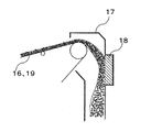
図2に示すように、傾斜コンベヤ16およびトリッパコンベア19は、搬送されてきたスラグをコンベヤから排出するための排口シュート17を有している。
As shown in FIG. 2, the
二次冷却によって100〜300℃程度にまで冷却されたスラグは高い硬度を有するため、コンベヤ16から排出されたスラグが排口シュート17に落下する部位で摩耗が生じやすい傾向があるが、本実施形態では、当該部分に、スラグ溜まり部18となる筺状の窪みを形成している。
Since the slag cooled to about 100 to 300 ° C. by the secondary cooling has high hardness, the slag discharged from the
コンベヤ16から排口シュート17に排出されるスラグが、一度このスラグ溜まり部18に溜まって当該部分をライニングすると、以後、このライニングされたスラグ溜まり部18が、コンベヤ16から落下してくるスラグを受け止めた後、排口シュート17の下方へ落下させることになる。
The slag discharged from the
なお、スラグ溜まり部18には、常に新たなスラグが落下してくるため、先に当該部分をライニングしていたスラグが欠損した場合であっても、次に落下してくるスラグによって速やかに復旧することができるため、安定的にセルフライニング施工が行われた状態を維持することができる。
In addition, since new slag always falls in the
このように、コンベヤ16から落下するスラグの有する運動エネルギーを、該スラグ溜まり部18に溜まったスラグへの衝突で吸収するセルフライニング構造とすることにより、搬送工程でスラグが落下する部位の摩耗による穴空きを効果的に防止することができる。
In this way, by adopting a cell flying structure that absorbs the kinetic energy of the slag falling from the
なお、スラグは熱伝導率が低いという特性を有するため、スラグを利用したセルフライニングによれば、例えば、スラグの落下点に耐火物等のライニング材を施工した場合に比べて、ライニングした下部構造物への熱負荷も低減することができる。 In addition, since slag has the characteristic that heat conductivity is low, according to the cell flying using slag, for example, compared to the case where lining material such as refractory is applied to the falling point of the slag, the substructure that is lined The heat load on the object can also be reduced.
1 スラグパン
2 ピット
10 冷却装置
11 ホッパー
12 篩分け用の格子
13 振動フィーダー
14 ケーシング
15 出口
16 傾斜コンベヤ
17 排口シュート
18 スラグ溜まり部
19 トリッパコンベア
20 製品ピット
DESCRIPTION OF SYMBOLS 1
Claims (4)
該コンベヤから排口シュート内に落下するスラグの落下点に、スラグ溜まり部となる筐体を設けたことを特徴とするスラグ搬送装置。 In a high-temperature slag processing apparatus used for processing high-temperature slag that primarily cools high-temperature slag and then performs secondary cooling while moving inside the cooling apparatus, a conveyor that conveys slag discharged from the outlet of the cooling apparatus; , A slag transport device comprising an outlet chute for discharging slag from the conveyor,
A slag transporting apparatus, wherein a casing serving as a slag reservoir is provided at a drop point of the slag falling into the discharge chute from the conveyor.
Priority Applications (1)
| Application Number | Priority Date | Filing Date | Title |
|---|---|---|---|
| JP2010149040A JP5582395B2 (en) | 2010-06-30 | 2010-06-30 | Slag transfer device |
Applications Claiming Priority (1)
| Application Number | Priority Date | Filing Date | Title |
|---|---|---|---|
| JP2010149040A JP5582395B2 (en) | 2010-06-30 | 2010-06-30 | Slag transfer device |
Publications (2)
| Publication Number | Publication Date |
|---|---|
| JP2012012148A true JP2012012148A (en) | 2012-01-19 |
| JP5582395B2 JP5582395B2 (en) | 2014-09-03 |
Family
ID=45599050
Family Applications (1)
| Application Number | Title | Priority Date | Filing Date |
|---|---|---|---|
| JP2010149040A Active JP5582395B2 (en) | 2010-06-30 | 2010-06-30 | Slag transfer device |
Country Status (1)
| Country | Link |
|---|---|
| JP (1) | JP5582395B2 (en) |
Cited By (2)
| Publication number | Priority date | Publication date | Assignee | Title |
|---|---|---|---|---|
| JP2020070165A (en) * | 2018-10-31 | 2020-05-07 | Jx金属株式会社 | Raw material supply device, electronic / electrical device component waste processing device, and electronic / electrical device component waste processing method |
| CN114180304A (en) * | 2021-12-09 | 2022-03-15 | 四川川锅锅炉有限责任公司 | A furnace front conveying system applied to high temperature ore |
Citations (4)
| Publication number | Priority date | Publication date | Assignee | Title |
|---|---|---|---|---|
| JPH0312807U (en) * | 1989-06-21 | 1991-02-08 | ||
| JPH05124720A (en) * | 1991-10-31 | 1993-05-21 | Nkk Corp | Chute for belt conveyor |
| JPH10273346A (en) * | 1997-03-27 | 1998-10-13 | Kawasaki Steel Corp | Manufacturing method of hard granulated blast furnace slag |
| JP2009127094A (en) * | 2007-11-26 | 2009-06-11 | Nippon Steel Corp | Method for collecting bullion in steelmaking slag |
-
2010
- 2010-06-30 JP JP2010149040A patent/JP5582395B2/en active Active
Patent Citations (4)
| Publication number | Priority date | Publication date | Assignee | Title |
|---|---|---|---|---|
| JPH0312807U (en) * | 1989-06-21 | 1991-02-08 | ||
| JPH05124720A (en) * | 1991-10-31 | 1993-05-21 | Nkk Corp | Chute for belt conveyor |
| JPH10273346A (en) * | 1997-03-27 | 1998-10-13 | Kawasaki Steel Corp | Manufacturing method of hard granulated blast furnace slag |
| JP2009127094A (en) * | 2007-11-26 | 2009-06-11 | Nippon Steel Corp | Method for collecting bullion in steelmaking slag |
Cited By (4)
| Publication number | Priority date | Publication date | Assignee | Title |
|---|---|---|---|---|
| JP2020070165A (en) * | 2018-10-31 | 2020-05-07 | Jx金属株式会社 | Raw material supply device, electronic / electrical device component waste processing device, and electronic / electrical device component waste processing method |
| WO2020090942A1 (en) * | 2018-10-31 | 2020-05-07 | Jx金属株式会社 | Raw material supply device, device for processing electronic and electric device part scraps, and method for processing electronic and electric device part scraps |
| US11649119B2 (en) | 2018-10-31 | 2023-05-16 | Jx Nippon Mining & Metals Corporation | Raw material supply device, device for processing electronic and electrical device part scraps, and method for processing electronic and electrical device part scraps |
| CN114180304A (en) * | 2021-12-09 | 2022-03-15 | 四川川锅锅炉有限责任公司 | A furnace front conveying system applied to high temperature ore |
Also Published As
| Publication number | Publication date |
|---|---|
| JP5582395B2 (en) | 2014-09-03 |
Similar Documents
| Publication | Publication Date | Title |
|---|---|---|
| CN103154275B (en) | Dry Granulation of Metallurgical Slag | |
| CN101874121B (en) | Treatment method of high temperature steelmaking slag or molten iron pretreatment slag | |
| JP5454747B1 (en) | Grinding material for shot blasting and its manufacturing method | |
| CN101871025B (en) | Metallurgical molten slag dry-type processing device and processing method thereof | |
| JP4418490B2 (en) | Method for collecting bullion in steelmaking slag | |
| CN107250078A (en) | A method and device for recycling white slag produced in iron and steel production steps | |
| CN103261443A (en) | Granulation of metallurgical slag | |
| JP5413742B2 (en) | High temperature slag treatment method | |
| JP5440957B2 (en) | High temperature slag processing equipment | |
| JP5582395B2 (en) | Slag transfer device | |
| JP4418489B2 (en) | High temperature slag treatment method | |
| JP5611454B2 (en) | Method and apparatus for producing glassy slag | |
| JP5998845B2 (en) | Heat recovery system and heat recovery method for solidified slag | |
| JP5320833B2 (en) | Vertical furnace operation method and vertical furnace charging coke in-furnace prevention equipment | |
| JP5505801B2 (en) | High temperature slag treatment method | |
| JP6601482B2 (en) | Steel slag treatment method and equipment | |
| KR102163183B1 (en) | Slag manufacturing device | |
| JP2017081811A (en) | Molten slag processing apparatus and molten slag processing method | |
| JP2009243833A (en) | Granular material transfer chute | |
| JP4719091B2 (en) | High temperature slag treatment equipment | |
| JP2016169888A (en) | Continuous cooling device and cooling method for powder | |
| CN103740942A (en) | Metal smelting slag separating and recycling production process | |
| JP4411631B2 (en) | Industrial waste recycling and collection method using shot blasting and industrial waste recycling and recovery equipment used in the method | |
| JP5573581B2 (en) | Waste water slag granulating apparatus and method | |
| JP2015147711A (en) | Slag manufacturing method, slag manufacturing system, and slag |
Legal Events
| Date | Code | Title | Description |
|---|---|---|---|
| A621 | Written request for application examination |
Free format text: JAPANESE INTERMEDIATE CODE: A621 Effective date: 20120809 |
|
| A977 | Report on retrieval |
Free format text: JAPANESE INTERMEDIATE CODE: A971007 Effective date: 20131127 |
|
| A131 | Notification of reasons for refusal |
Free format text: JAPANESE INTERMEDIATE CODE: A131 Effective date: 20131129 |
|
| A521 | Written amendment |
Free format text: JAPANESE INTERMEDIATE CODE: A523 Effective date: 20140117 |
|
| TRDD | Decision of grant or rejection written | ||
| A01 | Written decision to grant a patent or to grant a registration (utility model) |
Free format text: JAPANESE INTERMEDIATE CODE: A01 Effective date: 20140620 |
|
| A61 | First payment of annual fees (during grant procedure) |
Free format text: JAPANESE INTERMEDIATE CODE: A61 Effective date: 20140703 |
|
| R151 | Written notification of patent or utility model registration |
Ref document number: 5582395 Country of ref document: JP Free format text: JAPANESE INTERMEDIATE CODE: R151 |
|
| S533 | Written request for registration of change of name |
Free format text: JAPANESE INTERMEDIATE CODE: R313533 |
|
| R350 | Written notification of registration of transfer |
Free format text: JAPANESE INTERMEDIATE CODE: R350 |