JP2012012205A - Article reversing device - Google Patents
Article reversing device Download PDFInfo
- Publication number
- JP2012012205A JP2012012205A JP2010152691A JP2010152691A JP2012012205A JP 2012012205 A JP2012012205 A JP 2012012205A JP 2010152691 A JP2010152691 A JP 2010152691A JP 2010152691 A JP2010152691 A JP 2010152691A JP 2012012205 A JP2012012205 A JP 2012012205A
- Authority
- JP
- Japan
- Prior art keywords
- article
- rotating means
- rotating
- support member
- rotated
- Prior art date
- Legal status (The legal status is an assumption and is not a legal conclusion. Google has not performed a legal analysis and makes no representation as to the accuracy of the status listed.)
- Pending
Links
- 230000002265 prevention Effects 0.000 claims description 16
- 238000006073 displacement reaction Methods 0.000 claims description 5
- 238000005406 washing Methods 0.000 description 3
- 239000000428 dust Substances 0.000 description 2
- 230000009191 jumping Effects 0.000 description 2
- 238000011144 upstream manufacturing Methods 0.000 description 2
- 230000008602 contraction Effects 0.000 description 1
- 238000000034 method Methods 0.000 description 1
- 238000000926 separation method Methods 0.000 description 1
Images
Landscapes
- Attitude Control For Articles On Conveyors (AREA)
Abstract
Description
本発明は物品反転装置に関し、より詳しくは、物品を90°ずつ2度回転させることにより該物品を反転させるようにした物品反転装置に関する。 The present invention relates to an article reversing apparatus, and more particularly to an article reversing apparatus configured to invert an article by rotating the article by 90 ° twice.
従来、物品を90°回転させる第1回転手段と、この第1回転手段に隣接して配設され、上記物品を90°回転させる第2回転手段と、上記第1回転手段に上記物品を搬送する搬送手段とを備え、上記第1回転手段と第2回転手段とによってそれぞれ物品を90°回転させることにより該物品を反転させるようにした物品反転装置が知られている(特許文献1)。 Conventionally, first rotating means for rotating an article by 90 °, second rotating means arranged adjacent to the first rotating means for rotating the article by 90 °, and conveying the article to the first rotating means. There is known an article reversing device that includes a conveying means for rotating the article by rotating the article by 90 ° by the first rotating means and the second rotating means, respectively (Patent Document 1).
従来の物品反転装置においては、特定の大きさの物品を反転させるように設計されており、取り扱う物品の大小についての兼用性は考慮されていなかった。
つまり、仮に大きな物品を反転させるように設定した物品反転装置において、小さな物品を反転させようとした場合には、第1回転手段によって90°回転された物品は、第2回転手段からは離れた位置に位置することになる。そして、そのように離れた物品を第2回転手段で回転させようとした場合には、該物品が回転される過程で第2回転手段に衝突して破損されたり、あるいは物品の回転が不安定となって回転方向に対して横方向に飛び出したりする危険性があった。
他方、小さな物品を反転させるように設定した物品反転装置においては、大きな物品を反転させることは不可能であった。
本発明はそのような事情に鑑み、大小いずれの物品であっても円滑に反転させることができる物品反転装置を提供するものである。
The conventional article reversing device is designed to invert an article of a specific size, and the combined use of the size of the handled article has not been considered.
In other words, in an article reversing apparatus set to reverse a large article, if an attempt is made to reverse a small article, the article rotated 90 ° by the first rotating means is separated from the second rotating means. Will be in position. Then, when trying to rotate such an article separated by the second rotating means, the article collides with the second rotating means in the process of rotating the article, or the article rotation is unstable. There was a risk of jumping out in the direction transverse to the rotational direction.
On the other hand, in the article reversing apparatus set to invert a small article, it was impossible to invert a large article.
In view of such circumstances, the present invention provides an article reversing device capable of smoothly reversing an article of any size.
すなわち本発明は、物品を90°回転させる第1回転手段と、この第1回転手段に隣接して配設され、上記物品を90°回転させる第2回転手段と、上記第1回転手段に上記物品を搬送する搬送手段とを備え、上記第1回転手段と第2回転手段とによってそれぞれ物品を90°回転させることにより該物品を反転させるようにした物品反転装置において、
上記物品の大小に応じて、上記第1回転手段と第2回転手段との間隔を拡縮する間隔調整手段を設けたことを特徴とするものである。
That is, the present invention provides a first rotating means for rotating an article by 90 °, a second rotating means arranged adjacent to the first rotating means for rotating the article by 90 °, and the first rotating means to the above-mentioned first rotating means. An article reversing apparatus comprising: a conveying unit configured to convey an article, wherein the article is reversed by rotating the article by 90 ° by each of the first rotating unit and the second rotating unit.
In accordance with the size of the article, there is provided an interval adjusting means for expanding or reducing the interval between the first rotating means and the second rotating means.
本発明によれば、上記間隔調整手段により、物品の大小に応じて第1回転手段と第2回転手段との間隔を拡縮することができるので、例えば大きな物品を扱う場合には第1回転手段と第2回転手段との間隔をその大きな物品に最適な大きさに拡張することができ、また小さな物品を扱う場合には第1回転手段と第2回転手段との間隔をその小さな物品に最適な大きさに縮小することができる。
したがって本発明によれば、大きな物品と小さな物品とをそれぞれ円滑に反転させることができるようになる。
According to the present invention, since the interval between the first rotating means and the second rotating means can be enlarged or reduced by the distance adjusting means according to the size of the article, for example, when handling a large article, the first rotating means. The distance between the first rotating means and the second rotating means can be expanded to an optimum size for the large article, and when handling a small article, the distance between the first rotating means and the second rotating means is optimum for the small article. Can be reduced to any size.
Therefore, according to the present invention, a large article and a small article can be smoothly reversed.
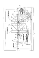
以下図示実施例について本発明を説明すると、図1、図2において、物品1(図3参照)を図の右方に向けて搬送する搬送手段2は所要の間隔をあけて平行に配置した2本のベルト3を備えており、各ベルト3は、図1に示すギヤモータ4によって回転駆動される駆動プーリ5にそれぞれ掛け渡され、各駆動プーリ5の回転によって同一速度で走行されるようになっている。
上記物品1は、図3で示す実施例では折りたたみ可能なコンテナであって、該コンテナの洗浄ラインにおいて、洗浄機手前でコンテナを反転させてその開口部を下方に向けさせることにより、上記洗浄機でコンテナ内部の洗浄を行なえるようにしてある。
The present invention will be described below with reference to the illustrated embodiments. In FIGS. 1 and 2, conveying means 2 for conveying an article 1 (see FIG. 3) toward the right side of the figure is arranged in parallel at a predetermined interval. The
The article 1 is a collapsible container in the embodiment shown in FIG. 3, and in the washing line of the container, the container is inverted before the washing machine and its opening is directed downward. The inside of the container can be cleaned.
上記搬送手段2の途中には、その上流側に上記物品1を90°回転させる第1回転手段11を設けるとともに、該第1回転手段11の下流側に第1回転手段11によって90°回転された物品1を更に90°回転させて該物品を反転させる第2回転手段12を設けてある。
上記第1回転手段11は、上記2本のベルト3の中間位置で、該ベルト3と直交する水平方向に配置した第1駆動軸13を備えており、この第1駆動軸13はブラシレスモータ14によって間欠的に90°ずつ回転駆動されるようになっている。
上記第1駆動軸13には、放射方向に各組4枚の板状の物品支持部材15a〜15dを固定してあり、各4枚の物品支持部材15a〜15dは互いに90°の間隔となるように十字状に配置してある。
上記第1駆動軸13の軸方向に隣接する物品支持部材(15a、15a)、(15b、15b)、(15c、15c)、(15d、15d)は、それぞれ互いに平行となるように配置してあり、かつ上記2本のベルト3の内側となるように配置してある。
In the middle of the conveying means 2, a
The
Each set of four plate-like article support
The article support members (15a, 15a), (15b, 15b), (15c, 15c), (15d, 15d) adjacent in the axial direction of the
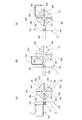
図3(a)で示すように、上記ブラシレスモータ14は、第1駆動軸13の回転方向を基準として、第1番目の物品支持部材15aと第3番目の物品支持部材15cとが水平となり、かつ第2番目の物品支持部材15bと第4番目の物品支持部材15dとが垂直となる位置で第1回転駆動軸13の回転を停止させ、図3(b)で示すように、そこから第1回転駆動軸13を図1の時計方向に90°回転させて、第1番目の物品支持部材15aと第3番目の物品支持部材15cとが垂直となり、かつ第2番目の物品支持部材15bと第4番目の物品支持部材15dとが水平となる位置で、第1回転駆動軸13の回転を停止させるようになっている。
そしてその際、図3(a)に示すように、ベルト3上に載置されて第1番目の物品支持部材15a上に搬入されるとともに、第2番目の物品支持部材15bに当接されて停止されている物品1を、図3(b)に示すように、それら物品支持部材の上記時計方向への90°の回転により、90°回転させることができるようにしてある。
As shown in FIG. 3A, in the
At that time, as shown in FIG. 3 (a), it is placed on the
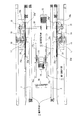
上記第2回転手段12は、図1、図2に示すように、上記2本のベルト3の外側位置で、該ベルト3と直交する水平方向に配置した2本の第2駆動軸17を備えており、両方の第2駆動軸17は一直線上となるように配置してある。
それぞれの第2駆動軸17は、各第2駆動軸17に固定したスプロケット18、各スプロケット18に掛け渡したチエン19、駆動軸20に固定したスプロケット21及び上記駆動軸20を介してブラシレスモータ22に連動しており、各第2駆動軸17は、上記ブラシレスモータ22によって同一方向に間欠的に90°ずつ回転駆動されるようになっている。
上記各第2駆動軸17のベルト3側の端部には、それぞれ十字形状のブラケット24を固定してあり、各ブラケット24に、ベルト3の外側の位置で、各組4枚の直角二等辺三角形状の横ずれ防止部材25a〜25dをそれぞれ固定してある。
As shown in FIGS. 1 and 2, the second rotating means 12 includes two
Each
A
図3(a)に示すように、直角二等辺三角形状の横ずれ防止部材25aは、互いに直交する二辺に一体的に物品支持部材25a’、25a”を備えており、したがって上記物品支持部材25a’と物品支持部材25a”との角度は互いに90°の角度となっている。上記物品支持部材25a’、25a”は横ずれ防止部材25aから内側に向けて、すなわち搬送手段2の中心に向けて板状に伸びており、軸方向に互いに対向する2つの物品支持部材25a’、25a’によって物品1をその底面側から支持することができるようにしてある。
その他の直角二等辺三角形状の横ずれ防止部材25b〜25dも、互いに直交する二辺に一体的に物品支持部材25b’〜25d’、25b”〜25d”を備えている。
各直角二等辺三角形状の横ずれ防止部材25a〜25dは、その頂部すなわちそれぞれの物品支持部材25a’〜25d’と25a”〜25d”との交点が駆動軸20側となるようにして上記ブラケット24に固定してあり、それによって例えば横ずれ防止部材25aの物品支持部材25a’とこれに隣接する横ずれ防止部材25dの物品支持部材25d”とが互いに平行となるように配置してある。
As shown in FIG. 3 (a), the right-angled isosceles triangular lateral
The other right-angled isosceles triangular lateral
Each of the right-angled isosceles triangle-shaped lateral
図3(a)、図3(b)で示すように、上記ブラシレスモータ22は、第2駆動軸17の回転方向を基準として、例えば第1番目の横ずれ防止部材25aにおける物品支持部材25a’が水平で、該横ずれ防止部材25aの物品支持部材25a”が垂直となる位置で第2回転駆動軸17の回転を停止させるようになっている。
そしてこの状態で図3(b)に示すように、第1回転手段11によって物品1が90°回転されると、該物品1は第1番目の横ずれ防止部材25aにおける物品支持部材25a’上に供給されるようになり、引き続きベルト3の走行により図3(b)の右方に移動されて該第1番目の横ずれ防止部材25aにおける物品支持部材25a”に当接してその移動が停止されるようになる。
As shown in FIGS. 3A and 3B, the
In this state, as shown in FIG. 3B, when the article 1 is rotated by 90 ° by the
そしてこの状態において、上記第2回転手段12のブラシレスモータ22が起動され、駆動軸20、スプロケット21、チェン19及びスプロケット17を介して第2駆動軸17が図3(b)の時計方向に90°回転される。これにより図3(c)に示すように、第1番目の物品支持部材25a’上に供給されていた物品1が90°回転されるようになる。
このようにして第2回転手段12によって回転された物品1は、この後、ベルト3によって外部に搬出されるようになる。
また、第2駆動軸17が図3(b)の時計方向に90°回転されることによって、第4番目の横ずれ防止部材25dにおける物品支持部材25d’が水平で、該横ずれ防止部材25dの物品支持部材25d”が垂直となり、これにより物品支持部材25d’は次の物品1を受け入れることが可能な状態となっている。
In this state, the
The article 1 thus rotated by the second
Further, when the
次に、上記物品1の大小に応じて、上記第1回転手段11と第2回転手段12との間隔を拡縮する間隔調整手段31について説明する。図1に示す実施例では、間隔調整手段31は、第1回転手段11を第2回転手段12に対して接離させることにより、両者の間隔を拡縮することができるようにしてある。
すなわち、固定フレーム32には、2本のベルト3の中央部下方位置で該ベルト3と平行にガイドレール33を敷設してあり、このガイドレール33上に移動フレーム34を移動可能に設けてある。上記第1回転手段11の第1駆動軸13は、上記移動フレーム34に回転自在に軸支してあり、したがって移動フレーム34を第2回転手段12側に移動させることにより第1回転手段11と第2回転手段12との間隔を縮小させ、また移動フレーム34を第2回転手段12とは反対側に移動させることにより第1回転手段11と第2回転手段12との間隔を拡大させることができるようにしてある。
Next, a description will be given of the interval adjusting unit 31 that enlarges or reduces the interval between the first
That is, a
上記固定フレーム32には、上記移動フレーム34を移動させる駆動手段35を設けてある。図示実施例では、駆動手段はシリンダ装置から構成してあり、該シリンダ装置の伸縮により、移動フレーム34を第2回転手段12に近接した位置と、離隔した位置とに移動させることができるようにしてある。
本実施例では、兼用する物品の大きさが大小2種類なので、それに合わせて移動フレーム34を第2回転手段12に近接した位置と、離隔した位置との2箇所に移動させることができるようにしているが、これに限定されるものではない。例えばベルト3と平行に配置したねじ軸と、移動フレーム34に設けられて該ねじ軸に螺合するナット部材と、さらに上記ねじ軸を回転させるサーボモータとから上記駆動手段35を構成することができ、それによって移動フレーム34を物品1の大小に応じて種々の最適な位置に移動させることができるようになる。
The fixed
In the present embodiment, since the size of the shared article is two kinds, large and small, the moving
さらに、上記第1回転手段11よりも上流側位置に、物品1の底面に係合して該物品の搬送を停止させるストッパ36を設けてあり、シリンダ装置37により該ストッパ36をベルト3の下方から上方へ突出させることにより、該ストッパ36に物品1の底面を係合させることができるようにしてある。
また図示しないが、上記第2回転手段12の下方に、上記物品1の内部に残存していたゴミなどを受けるゴミ受けを設けてある。
Further, a
Although not shown, a dust receiver is provided below the second rotating means 12 for receiving dust remaining inside the article 1.
以上の構成において、物品1の底面がストッパ36に係合している状態では、ベルト3が走行されていても物品1はそのストッパ36によって前進が阻止されている。
この状態から上記シリンダ装置37によりストッパ36がベルト3の下方に退没されると、該ストッパ36と物品1との係合が解除され、それにより物品1はベルト3によって右方に搬送されるようになる。この後ストッパ36は、シリンダ装置37により再び上昇されて、後続の物品1に係合してその前進を阻止するようになる。
他方、上記ベルト3によって搬送される物品1は、図3(a)に示すように、第1番目の物品支持部材15a上に搬入されるとともに、第2番目の物品支持部材15bに当接されてその前進が停止されるようになる。
上記物品1が第2番目の物品支持部材15bに当接されてその前進が停止されると、第1回転手段11の第1駆動軸13が時計方向へ90°回転され、それによって図3(b)に示すように、第1番目の物品支持部材15a上の物品1は該物品支持部材15aの回転に伴って上記時計方向へ90°回転されるようになる。
また、上記第1駆動軸13が時計方向へ90°回転されて停止されると、上記ストッパ36と物品1との係合が解除されて新たな物品1が第4番目の物品支持部材15d上に搬入されるようになる。
In the above configuration, in the state where the bottom surface of the article 1 is engaged with the
When the
On the other hand, the article 1 conveyed by the
When the article 1 is brought into contact with the second
When the
上記第1回転手段11の物品支持部材15aの回転に伴って回転される物品1は、第2回転手段12における第1番目の物品支持部材25a’上に供給されるようになる。このとき、該第1番目の横ずれ防止部材25aは、該物品支持部材25a’に供給される物品1の両側に位置しているので、物品1が大きく横方向に移動して第2回転手段12から飛び出そうとした際に、該物品1の側面に当接してその飛び出しを防止するようになる。
上記物品支持部材25a’上に供給された物品1は、引き続くベルト3の走行により図3(b)の右方に移動されて該第1番目の物品支持部材25a”に当接してその移動が停止されるようになる。
そしてこの状態となると、上記第2回転手段12の第2駆動軸17が図3(b)の時計方向に90°回転されるようになり、これによって図3(c)に示すように、第1番目の物品支持部材25a’上に供給されていた物品1が90°回転されるようになる。
このように、物品1は2度回転されて反転されるようになり、反転された物品1はベルト3によって例えば洗浄機内に搬入されて洗浄されるようになる。
The article 1 rotated in accordance with the rotation of the
The article 1 supplied on the
In this state, the
In this way, the article 1 is rotated twice and turned upside down, and the turned up article 1 is carried into the washing machine, for example, by the
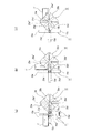
図3(a)〜図3(c)は大型の物品1を反転させる場合を示しているが、図4(a)〜図4(c)は小型の物品1’を反転させる場合を示したものである。
すなわち小型の物品1’を反転させる場合には、上記駆動手段35により移動フレーム34を第2回転手段12に近接した位置に移動させる。これにより、図4(a)に示すように、移動フレーム34に設けた第1回転手段11は、想像線で示す大型の物品1を反転させる場合の位置から、実線で示す小型の物品1’を反転させる場合の位置まで第2回転手段12側に移動され、それによって第1回転手段11と第2回転手段12との間隔が縮小される。
これにより図4(b)から理解されるように、第1回転手段11と第2回転手段12との間隔は小型の物品1’に好適な間隔となり、第1回転手段11によって90°回転される小型の物品1’は、円滑に第2回転手段12における第1番目の物品支持部材25a’上に供給されるようになる。
そして物品支持部材25a’上に供給された小型の物品1’は、上述したのと同様に、第2回転手段12によって更に90°回転されて反転されるようになる。
3 (a) to 3 (c) show the case where the large article 1 is inverted, while FIGS. 4 (a) to 4 (c) show the case where the small article 1 'is inverted. Is.
That is, when the small article 1 ′ is reversed, the moving
As a result, as understood from FIG. 4B, the interval between the first
Then, the small article 1 ′ supplied on the
なお上記実施例では、間隔調整手段31は第1回転手段11を第2回転手段12に対して接離させるようにしているが、第2回転手段12を第1回転手段11に対して接離させるようにしてもよく、必要に応じて双方を接離可能に設けてもよい。このとき、図示しないが、第1回転手段11へ供給される物品の大きさを検出する検出器を設けて、間隔調整手段31によって自動的に第1回転手段11と第2回転手段12との間隔をその物品の大きさに応じて調整できるようにしてもよく、この場合には、大型の物品1と小型の物品1’とを混在させても、それぞれを円滑に反転させることが可能となる。
また上記実施例では、搬送手段2は第1回転手段11と第2回転手段12との間に亘って設けてあるが、これを省略してもよい。つまり搬送手段2を、第1回転手段11に物品を供給する搬送手段と、第2回転手段12から物品を搬出する搬送手段とに分割して、上記第1回転手段11と第2回転手段12との間の搬送手段を省略しても良い。この場合であっても、間隔調整手段31によって第1回転手段11と第2回転手段12との間隔を物品の大きさに応じて最適な大きさに調整すれば、第2回転手段12によって大型の物品1と小型の物品1’とをそれぞれ円滑に反転させることができる。
さらに上記実施例では搬送手段2の駆動源としてギヤモータ4を、また第1回転手段11と第2回転手段12の駆動源としてブラシレスモータ14、22をそれぞれ用いているが、これらに限定されるものではなく、サーボモータなどの適宜の駆動源を用いることができる。
In the above-described embodiment, the interval adjusting unit 31 is configured to bring the first
Moreover, in the said Example, although the conveyance means 2 is provided between the 1st rotation means 11 and the 2nd rotation means 12, this may be abbreviate | omitted. That is, the conveying means 2 is divided into a conveying means for supplying articles to the first
Further, in the above embodiment, the
1、1’ 物品 2 搬送手段
3 ベルト 11 第1回転手段
12 第2回転手段 13 第1駆動軸
15a〜15d、25a’〜25d’、25a”〜25d” 物品支持部材
17 第2駆動軸 25a〜25d 横ずれ防止部材
31 間隔調整手段 33 ガイドレール
34 移動フレーム 35 駆動手段
DESCRIPTION OF SYMBOLS 1, 1 'goods 2 Conveyance means 3
Claims (4)
上記物品の大小に応じて、上記第1回転手段と第2回転手段との間隔を拡縮する間隔調整手段を設けたことを特徴とする物品反転装置。 First rotating means for rotating the article by 90 °, second rotating means arranged adjacent to the first rotating means for rotating the article by 90 °, and transport for conveying the article to the first rotating means Means for reversing the article by rotating the article by 90 ° by the first rotating means and the second rotating means, respectively,
An article reversing apparatus, comprising: an interval adjusting unit that expands or contracts the interval between the first rotating unit and the second rotating unit according to the size of the article.
Priority Applications (1)
| Application Number | Priority Date | Filing Date | Title |
|---|---|---|---|
| JP2010152691A JP2012012205A (en) | 2010-07-05 | 2010-07-05 | Article reversing device |
Applications Claiming Priority (1)
| Application Number | Priority Date | Filing Date | Title |
|---|---|---|---|
| JP2010152691A JP2012012205A (en) | 2010-07-05 | 2010-07-05 | Article reversing device |
Publications (1)
| Publication Number | Publication Date |
|---|---|
| JP2012012205A true JP2012012205A (en) | 2012-01-19 |
Family
ID=45599097
Family Applications (1)
| Application Number | Title | Priority Date | Filing Date |
|---|---|---|---|
| JP2010152691A Pending JP2012012205A (en) | 2010-07-05 | 2010-07-05 | Article reversing device |
Country Status (1)
| Country | Link |
|---|---|
| JP (1) | JP2012012205A (en) |
Cited By (2)
| Publication number | Priority date | Publication date | Assignee | Title |
|---|---|---|---|---|
| CN112548755A (en) * | 2020-12-09 | 2021-03-26 | 德清恒凌五金有限公司 | Corner polisher for wood board processing |
| CN116331794A (en) * | 2023-05-05 | 2023-06-27 | 贵阳普天物流技术有限公司 | A device and method for quickly realizing the flipping of box-type objects |
Citations (7)
| Publication number | Priority date | Publication date | Assignee | Title |
|---|---|---|---|---|
| JPS50120175U (en) * | 1974-03-18 | 1975-10-01 | ||
| JPS5711128U (en) * | 1980-06-20 | 1982-01-20 | ||
| JPH0587491U (en) * | 1992-04-22 | 1993-11-26 | 沖電気工業株式会社 | Board insertion / ejection structure |
| JPH0940155A (en) * | 1995-07-24 | 1997-02-10 | Furukawa Electric Co Ltd:The | Disk reversal processing method and device |
| JPH11268710A (en) * | 1998-01-20 | 1999-10-05 | Natec Reich Summer Gmbh Co Kg | Method and device for depositing unpackaged process cheese piece |
| JP2002046853A (en) * | 2000-08-01 | 2002-02-12 | Mitsubishi Heavy Ind Ltd | Slab reversing device |
| JP2002120930A (en) * | 2000-10-16 | 2002-04-23 | Sony Corp | Article separation and transfer device |
-
2010
- 2010-07-05 JP JP2010152691A patent/JP2012012205A/en active Pending
Patent Citations (7)
| Publication number | Priority date | Publication date | Assignee | Title |
|---|---|---|---|---|
| JPS50120175U (en) * | 1974-03-18 | 1975-10-01 | ||
| JPS5711128U (en) * | 1980-06-20 | 1982-01-20 | ||
| JPH0587491U (en) * | 1992-04-22 | 1993-11-26 | 沖電気工業株式会社 | Board insertion / ejection structure |
| JPH0940155A (en) * | 1995-07-24 | 1997-02-10 | Furukawa Electric Co Ltd:The | Disk reversal processing method and device |
| JPH11268710A (en) * | 1998-01-20 | 1999-10-05 | Natec Reich Summer Gmbh Co Kg | Method and device for depositing unpackaged process cheese piece |
| JP2002046853A (en) * | 2000-08-01 | 2002-02-12 | Mitsubishi Heavy Ind Ltd | Slab reversing device |
| JP2002120930A (en) * | 2000-10-16 | 2002-04-23 | Sony Corp | Article separation and transfer device |
Cited By (2)
| Publication number | Priority date | Publication date | Assignee | Title |
|---|---|---|---|---|
| CN112548755A (en) * | 2020-12-09 | 2021-03-26 | 德清恒凌五金有限公司 | Corner polisher for wood board processing |
| CN116331794A (en) * | 2023-05-05 | 2023-06-27 | 贵阳普天物流技术有限公司 | A device and method for quickly realizing the flipping of box-type objects |
Similar Documents
| Publication | Publication Date | Title |
|---|---|---|
| KR101738861B1 (en) | Reversing apparatus of packing receptacle for automatic packaging system | |
| TWI653702B (en) | High volume conveyor transport for clean environments | |
| JP2012096888A (en) | Box reversal device | |
| KR20080109603A (en) | Roller conveyor and conveying control method | |
| WO2019131826A1 (en) | Cargo handling device and cargo handling method | |
| US9957114B2 (en) | Multi-conveyor speed adjuster | |
| JP6129122B2 (en) | Turntable | |
| JP2015020858A (en) | Article transfer device | |
| JP2012012205A (en) | Article reversing device | |
| JP2005053662A (en) | Direction changing device for article | |
| JP2009046224A (en) | Transport device | |
| JP5289806B2 (en) | Transport device | |
| JP4997501B2 (en) | Reverse transfer device | |
| JP2018030680A (en) | Transfer equipment | |
| JP4883611B2 (en) | Direction change device | |
| JP2005067863A (en) | Direction changing device | |
| US5735389A (en) | Conveying system | |
| KR20170124263A (en) | Chain conveyer assembly | |
| JP5800965B1 (en) | Transport device | |
| JP2015074549A (en) | Reversing machine | |
| CN206318414U (en) | Transmit frock | |
| CN205312697U (en) | Carousel formula transition conveyer | |
| JP6559962B2 (en) | Posture change mechanism and boxing device provided with the same | |
| JP3179762U (en) | Direction change transfer device | |
| JPH09240823A (en) | Transfer device |
Legal Events
| Date | Code | Title | Description |
|---|---|---|---|
| A621 | Written request for application examination |
Free format text: JAPANESE INTERMEDIATE CODE: A621 Effective date: 20130628 |
|
| A131 | Notification of reasons for refusal |
Free format text: JAPANESE INTERMEDIATE CODE: A131 Effective date: 20140603 |
|
| A02 | Decision of refusal |
Free format text: JAPANESE INTERMEDIATE CODE: A02 Effective date: 20141021 |