JP2012012208A - Conveyance chain - Google Patents
Conveyance chain Download PDFInfo
- Publication number
- JP2012012208A JP2012012208A JP2010152826A JP2010152826A JP2012012208A JP 2012012208 A JP2012012208 A JP 2012012208A JP 2010152826 A JP2010152826 A JP 2010152826A JP 2010152826 A JP2010152826 A JP 2010152826A JP 2012012208 A JP2012012208 A JP 2012012208A
- Authority
- JP
- Japan
- Prior art keywords
- pair
- chain
- inner plate
- press
- bush
- Prior art date
- Legal status (The legal status is an assumption and is not a legal conclusion. Google has not performed a legal analysis and makes no representation as to the accuracy of the status listed.)
- Granted
Links
- 230000002093 peripheral effect Effects 0.000 claims abstract description 20
- 238000005299 abrasion Methods 0.000 abstract 1
- 230000032258 transport Effects 0.000 description 49
- 238000010586 diagram Methods 0.000 description 6
- 230000000694 effects Effects 0.000 description 5
- 230000037431 insertion Effects 0.000 description 4
- 238000003780 insertion Methods 0.000 description 4
- 239000003337 fertilizer Substances 0.000 description 3
- 239000000463 material Substances 0.000 description 3
- 238000005452 bending Methods 0.000 description 1
- 230000007423 decrease Effects 0.000 description 1
- 239000010687 lubricating oil Substances 0.000 description 1
- 230000002250 progressing effect Effects 0.000 description 1
Images


Landscapes
- Chain Conveyers (AREA)
Abstract
Description
本発明は、搬送物を捕捉して搬送する搬送用チェーンに関するものであって、特に、左右一対のブラケット部材が搬送手段によって相互に連結されている搬送用チェーンに関する。 The present invention relates to a transport chain that captures and transports a transported object, and particularly relates to a transport chain in which a pair of left and right bracket members are connected to each other by transport means.
搬送用チェーンは、使用環境に応じて、強度や耐摩耗性が要求される。一方で、摩耗が進行した場合には、搬送用チェーンを分解して摩耗箇所を速やかに交換できることが望ましい。 The transport chain is required to have strength and wear resistance depending on the use environment. On the other hand, when wear progresses, it is desirable that the carrying chain can be disassembled so that the worn portion can be quickly replaced.
従来、対向して設けられ、両端にピン孔を有する一対の外プレートと、外プレートの内側に配置されて、両端にブシュ孔を有する一対の内プレートと、内プレートの内側に設けられて内部に貫通孔を有するブシュと、外プレートのピン孔、内プレートのブシュ孔及びブシュの貫通孔を貫通して外プレート及び内プレートを回転可能に連結するピンとを備える搬送用チェーンが知られている(例えば、特許文献1参照)。
そして、このような搬送用チェーンのピンは、ピンの脱落を防止するための抜け止め挿入孔を有しており、抜け止め部材が、抜け止め挿入孔に挿入されている。
また、従来の搬送用チェーンにおいては、搬送物を搬送するバケット等の搬送手段を外プレートのアタッチメント取付部にボルト等で接合するものが知られている。
Conventionally, a pair of outer plates provided facing each other and having pin holes at both ends, a pair of inner plates disposed inside the outer plates and having bush holes at both ends, and provided inside the inner plate There is known a transport chain including a bush having a through hole in the outer plate, a pin hole in the outer plate, a bush hole in the inner plate, and a pin that rotatably connects the outer plate and the inner plate through the bush through hole. (For example, refer to Patent Document 1).
And the pin of such a conveyance chain has a retaining insertion hole for preventing the pin from falling off, and a retaining member is inserted into the retaining insertion hole.
In addition, in a conventional transport chain, a transporting means such as a bucket for transporting a transported object is known to be joined to an attachment mounting portion of an outer plate with a bolt or the like.
前述したような従来の分解可能な搬送用チェーンでは、チェーン組立時のピンの脱落を防止するための抜け止め部材の挿入とアタッチメント取付時のチェーンとアタッチメントとの接合のためのボルト等の装着は別個に行う必要があり、また、左右一対の外プレートのアタッチメント取付部にアタッチメントを接続するアタッチメント式搬送用チェーンでは、スプロケットとの噛み合いによる衝撃荷重に起因してローラに損傷が生じた場合には、アタッチメントを取り外した上でチェーンを分解してローラを交換する必要があり、チェーンの組立、分解に多大な時間を要するという問題があった。 In the conventional chain that can be disassembled as described above, it is necessary to insert a retaining member to prevent the pin from falling off when assembling the chain and to attach a bolt or the like for joining the chain and the attachment when attaching the attachment. In the case of an attachment-type transport chain in which attachments are connected to attachment attachment parts of a pair of left and right outer plates, if the roller is damaged due to impact load due to meshing with the sprocket, Since it is necessary to disassemble the chain after removing the attachment and replace the roller, there is a problem that it takes a lot of time to assemble and disassemble the chain.
また、チェーンの屈曲動作を確保するためにピンが外プレートに遊嵌されており、ピンと外プレートのプレート孔の面圧が高くなるため摩耗進行が早く、また、ピンとプレート孔との間に間隙が存在するためチェーンの疲労強度が下がるという問題があった。 In addition, the pin is loosely fitted to the outer plate to ensure the chain bending action, and the surface pressure of the pin hole of the pin and the outer plate increases, so that the wear progresses quickly, and there is a gap between the pin and the plate hole. There is a problem that the fatigue strength of the chain decreases because of the presence of
そして、ローラを介してスプロケットに噛み合う搬送用チェーンにおいては、1つのスプロケットを用いてチェーンを駆動させているため、搬送用チェーンに捩れが発生して、搬送物の捕捉搬送が不安定になるという問題があった。 In the transport chain that meshes with the sprocket via the roller, the chain is driven by using one sprocket, so that the transport chain is twisted, and the capture and transport of the transported object becomes unstable. There was a problem.
そこで、本発明は、従来の問題を解決するものであって、すなわち、本発明の目的は、搬送用チェーンの組立、分解を容易に達成して、チェーンの摩耗進行を防止して、チェーンの疲労強度を上げるとともに、搬送用チェーンの捩れを防止して、安定して搬送物を捕捉搬送する搬送用チェーンを提供することである。 Therefore, the present invention solves the conventional problems, that is, the object of the present invention is to easily assemble and disassemble the transport chain to prevent the chain from progressing and An object of the present invention is to provide a transport chain that increases the fatigue strength and prevents twisting of the transport chain, and stably captures and transports the transported object.
請求項1に係る本発明は、前後一対のピン圧入孔を有する内プレートと、内プレートのピン圧入孔に圧入嵌合される連結ピンと、連結ピンの外周面に内プレートの左右両側からそれぞれ遊嵌する左右一対のブシュと、ブシュの一端を前後一対のブシュ圧入孔にそれぞれ圧入嵌合するとともに前記連結ピンを介して内プレートをチェーン長手方向に相互に連結する左右一対の外プレートと、ブシュの外周面に遊嵌するローラと、ブシュの他端に着脱自在に遊嵌して支持する盲孔を有する左右一対のブラケット部材と、左右一対のブラケット部材を相互に連結して搬送物を捕捉する搬送手段とで構成されていることにより、前述した課題を解決したものである。 According to the first aspect of the present invention, there is provided an inner plate having a pair of front and rear pin press-fitting holes, a connecting pin press-fitted into the pin press-fitting hole of the inner plate, and an outer peripheral surface of the connecting pin from both the left and right sides of the inner plate. A pair of left and right bushes to be fitted, a pair of left and right outer plates for fitting one end of the bushing into a pair of front and rear bushing press-fitting holes and connecting the inner plate to each other in the longitudinal direction of the chain via the connecting pin A pair of left and right bracket members having a roller that is loosely fitted to the outer peripheral surface of the bush, a blind hole that is detachably fitted to and supported by the other end of the bush, and a pair of left and right bracket members are connected to each other to capture the conveyed product. The above-described problems are solved by being constituted by the conveying means.
請求項2に係る本発明は、請求項1記載の構成に加えて、左右一対の外プレートが、内プレートに近接して対向配置していることにより、ローラが外プレートとブラケット部材との間に配置されることにより、前述した課題をさらに解決したものである。 According to a second aspect of the present invention, in addition to the configuration according to the first aspect, the pair of left and right outer plates are disposed so as to face each other close to the inner plate, so that the roller is disposed between the outer plate and the bracket member. The above-described problems are further solved by being arranged in the above.
請求項3に係る本発明は、請求項1または請求項2記載の構成に加えて、左右一対のブラケット部材と搬送手段とが、ボルトとナットとからなる締結手段によって着脱自在に連結されていることにより、前述した課題をさらに解決したものである。 According to a third aspect of the present invention, in addition to the configuration of the first or second aspect, the pair of left and right bracket members and the conveying means are detachably connected by fastening means including bolts and nuts. Thus, the above-described problems are further solved.
請求項4に係る本発明は、請求項1乃至請求項3のいずれかに記載の構成に加えて、搬送手段が、搬送物を捕捉して搬送するバケットで構成されていることにより、前述した課題をさらに解決したものである。 In addition to the structure according to any one of claims 1 to 3, the present invention according to claim 4 is described above because the transport means is configured by a bucket that captures and transports a transported object. It solves the problem further.
そこで、本発明は、前後一対のピン圧入孔を有する内プレートと、内プレートのピン圧入孔に圧入嵌合される連結ピンと、連結ピンの外周面に内プレートの左右両側からそれぞれ遊嵌する左右一対のブシュと、ブシュの一端を前後一対のブシュ圧入孔にそれぞれ圧入嵌合するとともに連結ピンを介して内プレートをチェーン長手方向に相互に連結する左右一対の外プレートと、ブシュの外周面に遊嵌するローラと、ブシュの他端に着脱自在に遊嵌して支持する盲孔を有する左右一対のブラケット部材と、左右一対のブラケット部材を相互に連結して搬送物を捕捉する搬送手段とで構成されていることにより、チェーンの周回走行によって搬送手段により搬送物を捕捉して搬送するばかりでなく、以下のような特有の効果を奏することができる。 Therefore, the present invention provides an inner plate having a pair of front and rear pin press-fitting holes, a connecting pin press-fitted into the pin press-fitting hole of the inner plate, and left and right sides that are loosely fitted to the outer peripheral surface of the connecting pin from the left and right sides of the inner plate. A pair of bushings, a pair of left and right outer plates that press-fit one end of the bushings into a pair of front and rear bushing press-fit holes and connect the inner plates to each other in the longitudinal direction of the chain via a connecting pin, and an outer peripheral surface of the bushing A roller for loose fitting, a pair of left and right bracket members having a blind hole that is detachably loosely fitted to and supported by the other end of the bush, and a conveying means for connecting the pair of left and right bracket members to each other to capture a conveyed product By being constituted by the chain, not only the transported object is captured and transported by the transporting means by the circular traveling of the chain, but also the following specific effects can be achieved.
請求項1に係る本発明の搬送用チェーンによれば、ブシュの他端に着脱自在に遊嵌して支持する盲孔を有する左右一対のブラケット部材と、左右一対のブラケット部材を相互に連結して搬送物を捕捉する搬送手段とで構成されていることにより、搬送手段とブラケット部材との連結のみによって搬送用チェーン全体を連結するため、容易に搬送用チェーンを組立、分解することができ、また、スプロケットとの噛み合いによる衝撃荷重に起因してローラに損傷が生じた場合であっても、ローラを容易に交換することができる。 According to the carrying chain of the present invention according to claim 1, the pair of left and right bracket members having a blind hole that is detachably fitted to and supported by the other end of the bush and the pair of left and right bracket members are connected to each other. Since the entire transport chain is connected only by connecting the transport means and the bracket member, the transport chain can be easily assembled and disassembled. Further, even when the roller is damaged due to an impact load caused by meshing with the sprocket, the roller can be easily replaced.
また、前後一対のピン圧入孔を有する内プレートと、内プレートのピン圧入孔に圧入嵌合される連結ピンと、連結ピンの外周面に内プレートの左右両側からそれぞれ遊嵌する左右一対のブシュと、ブシュの一端を前後一対のブシュ圧入孔にそれぞれ圧入嵌合するとともに連結ピンを介して内プレートをチェーン長手方向に相互に連結する左右一対の外プレートとで構成されていることにより、連結ピンと内プレートとの間およびブシュと外プレートとの間に間隙がないため、搬送用チェーンの疲労強度を向上させるとともに、圧入部分における摩耗損傷の発生を防止することができる。 Also, an inner plate having a pair of front and rear pin press-fitting holes, a connecting pin press-fitted into the pin press-fitting hole of the inner plate, and a pair of left and right bushes fitted loosely from the left and right sides of the inner plate to the outer peripheral surface of the connecting pin, And a pair of left and right outer plates that press-fit one end of the bushing into a pair of front and rear bushing press-fit holes and connect the inner plate to each other in the longitudinal direction of the chain via the connecting pin, Since there is no gap between the inner plate and between the bush and the outer plate, the fatigue strength of the conveying chain can be improved and the occurrence of wear damage at the press-fit portion can be prevented.
さらに、連結ピンの外周面に内プレートの左右両側からそれぞれ遊嵌する左右一対のブシュと、ブシュの一端を前後一対のブシュ圧入孔にそれぞれ圧入嵌合するとともに連結ピンを介して内プレートをチェーン長手方向に相互に連結する左右一対の外プレートと、ブシュの外周面に遊嵌するローラとで構成されていることにより、2個のスプロケットが左右一対のローラにそれぞれ当接して搬送用チェーンを駆動させるため、搬送用チェーンの捩れを防止するとともに、安定して搬送物を捕捉して搬送することができる。 Further, a pair of left and right bushes that are loosely fitted to the outer peripheral surface of the connecting pin from both the left and right sides of the inner plate, one end of the bushing is press-fitted into a pair of front and rear bushing press-fit holes, and the inner plate is chained via the connecting pin. By comprising a pair of left and right outer plates that are mutually connected in the longitudinal direction and a roller that is loosely fitted to the outer peripheral surface of the bush, the two sprockets abut against the pair of left and right rollers, respectively. Since it is driven, twisting of the transport chain can be prevented, and the transported object can be captured and transported stably.
請求項2に係る本発明の搬送用チェーンによれば、請求項1記載の搬送用チェーンが奏する効果に加えて、左右一対の外プレートが、内プレートに近接して対向配置していることにより、ローラが外プレートとブラケット部材との間に配置されるため、搬送手段とブラケット部材との連結を解除し、ブラケット部材を取り外すことで、摩耗損傷したローラの交換を容易に達成することができる。 According to the transport chain of the present invention according to claim 2, in addition to the effect exerted by the transport chain according to claim 1, the pair of left and right outer plates are disposed so as to face each other close to the inner plate. Since the roller is disposed between the outer plate and the bracket member, it is possible to easily replace the wear-damaged roller by releasing the connection between the conveying means and the bracket member and removing the bracket member. .
請求項3に係る本発明の搬送用チェーンによれば、請求項1または請求項2記載の搬送用チェーンが奏する効果に加えて、左右一対のブラケット部材と搬送手段とが、ボルトとナットとからなる締結手段によって着脱自在に連結されていることにより、搬送手段とブラケット部材とを連結するために必要な力をボルトとナットとの締め付け力により得られるため、簡単かつ確実に搬送用チェーンを組立、分解することができる。 According to the conveying chain of the present invention according to claim 3, in addition to the effect exerted by the conveying chain according to claim 1 or 2, the pair of left and right bracket members and the conveying means include a bolt and a nut. Because it is detachably connected by the fastening means, the force required to connect the transport means and the bracket member can be obtained by the tightening force of the bolt and nut, so that the transport chain can be assembled easily and reliably. Can be disassembled.
請求項4に係る本発明の搬送用チェーンによれば、請求項1乃至請求項3のいずれかに記載の搬送用チェーンが奏する効果に加えて、搬送手段が、搬送物を搬送するバケットで構成されていることにより、バケットで搬送物を掻き取るため、肥料、試料、穀物等のばらものであっても効率的に捕捉搬送することができる。 According to the conveying chain of the present invention according to claim 4, in addition to the effect exhibited by the conveying chain according to any one of claims 1 to 3, the conveying means is constituted by a bucket for conveying an object to be conveyed. As a result, the conveyed item is scraped off by the bucket, so that even a loose material such as a fertilizer, a sample, and a grain can be efficiently captured and conveyed.
本発明は、前後一対のピン圧入孔を有する内プレートと、内プレートのピン圧入孔に圧入嵌合される連結ピンと、連結ピンの外周面に内プレートの左右両側からそれぞれ遊嵌する左右一対のブシュと、ブシュの一端を前後一対のブシュ圧入孔にそれぞれ圧入嵌合するとともに連結ピンを介して内プレートをチェーン長手方向に相互に連結する左右一対の外プレートと、ブシュの外周面に遊嵌するローラと、ブシュの他端に着脱自在に遊嵌して支持する盲孔を有する左右一対のブラケット部材と、左右一対のブラケット部材を相互に連結して搬送物を捕捉する搬送手段とで構成されて、容易にチェーンの組み立て、分解を達成するものであれば、その具体的な実施の形態は、如何なるものであっても何ら構わない。 The present invention includes an inner plate having a pair of front and rear pin press-fitting holes, a connecting pin that is press-fitted into the pin press-fitting hole of the inner plate, and a pair of left and right sides that are loosely fitted to the outer peripheral surface of the connecting pin from the left and right sides of the inner plate. A bush, a pair of left and right outer plates that press-fit one end of the bush into a pair of front and rear bushing press-fit holes and connect the inner plate to each other in the longitudinal direction of the chain via a connecting pin, and loosely fit to the outer peripheral surface of the bush And a pair of left and right bracket members having a blind hole that is detachably fitted to and supported by the other end of the bush, and a conveying means for connecting the pair of left and right bracket members to each other to capture a conveyed product. As long as the assembly and disassembly of the chain can be easily achieved, any specific embodiment may be used.
また、本発明の搬送用チェーンに組み込まれる搬送手段は、左右一対のブラケットを相互に連結するとともに、搬送物を捕捉して搬送するものであれば、バケット、スラット、パンまたはエプロンなどのいずれであっても構わない。 In addition, the conveying means incorporated in the conveying chain of the present invention can be a bucket, a slat, a pan or an apron as long as it couples the left and right brackets to each other and captures and conveys the conveyed item. It does not matter.
以下、本発明の一実施例である搬送用チェーン100を図1乃至図7に基づいて説明する。
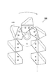
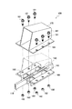
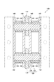
ここで、図1は、本発明の搬送用チェーンを適用したバケットエレベータの概要図であり、図2は、本発明の一実施例である搬送用チェーンの概要図であり、図3は、本発明の一実施例である、搬送手段を除く搬送用チェーンの概要図であり、図4は、図3に示す搬送用チェーンの組み立て分解図であり、図5は、本発明の一実施例である搬送用チェーンの使用態様図であり、図6は、本発明の一実施例である搬送手段を除く搬送用チェーンの平面図であり、図7は、図5に示す搬送用チェーンのA−A断面図である。
Hereinafter, a
Here, FIG. 1 is a schematic diagram of a bucket elevator to which the conveyance chain of the present invention is applied, FIG. 2 is a schematic diagram of a conveyance chain that is an embodiment of the present invention, and FIG. FIG. 4 is a schematic diagram of a transport chain excluding transport means according to an embodiment of the invention, FIG. 4 is an exploded view of the transport chain shown in FIG. 3, and FIG. 5 is an embodiment of the present invention. FIG. 6 is a plan view of a transport chain excluding transport means according to an embodiment of the present invention, and FIG. 7 is an A- view of the transport chain shown in FIG. It is A sectional drawing.
まず、本発明の実施例である搬送用チェーン100は、肥料、試料、穀物等のばらものを捕捉搬送するためのコンベヤチェーンに用いられるものであって、図2乃至図7に示すように、前後一対のピン圧入孔112を有する内プレート110と、内プレート110のピン圧入孔112に圧入嵌合される連結ピン120と、この連結ピン120の外周面に内プレート110の左右両側からそれぞれ遊嵌する左右一対のブシュ130,130と、このブシュ130の一端を前後一対のブシュ圧入孔142にそれぞれ圧入嵌合するとともに連結ピン130を介して内プレート110をチェーン長手方向に相互に連結する左右一対の外プレート140、140とを備えている。
また、搬送用チェーン100は、ブシュ130の外周面に遊嵌するローラ150と、ブシュ130の他端に着脱自在に遊嵌して支持する盲孔162を有する左右一対のブラケット部材160,160と、左右一対のブラケット部材160、160を相互に連結する搬送手段170とを備えている。
First, a
The
搬送用チェーン100は、ばらもの等の搬送物Wを捕捉して搬送するバケットからなる搬送手段170を備えており、この搬送手段170を介してブラケット部材160、160が相互に連結されている。
ブラケット部材160と搬送手段170とは、搬送手段170に設けられた孔とブラケット部材160のボルト挿入孔164とに挿入するボルト181と、このボルト181に係合するナット182とをブラケット部材160と搬送手段170とを挟持して締め付けることで結合されている。
The
The
連結ピン130が、図7に示すように、ブシュ130に遊嵌するピン小径部122と内プレート110に圧入嵌合するピン大径部124とで構成され、ブシュ130の端部が、ピン大径部124に当接し、ブシュ130の他端が、盲孔162に当接しており、潤滑油が、ブシュ130とピン小径部122とピン大径部124と盲孔162との間に封入されている。
As shown in FIG. 7, the connecting
そこで、本実施例の搬送用チェーン100が最も特徴とするブラケット部材160と搬送手段170の具体的な形態について図2乃至図7により詳しく説明する。
まず、本実施例の搬送用チェーン100が、ブシュ130の他端に着脱自在に遊嵌して支持する盲孔162を有する左右一対のブラケット部材160、160と、左右一対のブラケット部材160、160を相互に連結して搬送物を捕捉する搬送手段170とを備えている。
これにより、ブラケット部材160と搬送手段170との連結のみによって搬送用チェーン100全体を連結している。
Therefore, specific forms of the
First, a pair of left and
As a result, the
また、本実施例の搬送用チェーン100が、内プレート110と、内プレート110のピン圧入孔112に圧入嵌合される連結ピン120と、連結ピン120の外周面に内プレート110の左右両側からそれぞれ遊嵌する左右一対のブシュ130、130と、ブシュ130の一端を前後一対のブシュ圧入孔142にそれぞれ圧入嵌合するとともに前記連結ピン120を介して内プレート110をチェーン長手方向に相互に連結する左右一対の外プレート140、140とを備えている。
これにより、連結ピン120と内プレート110との間およびブシュ130と外プレート140との間に間隙がないように構成されている。
Further, the
Accordingly, there is no gap between the connecting
さらに、本実施例の搬送用チェーン100が、連結ピン120の外周面に内プレート110の左右両側からそれぞれ遊嵌する左右一対のブシュ130、130と、ブシュ130の一端を前後一対のブシュ圧入孔142にそれぞれ圧入嵌合するとともに前記連結ピン120を介して内プレート110をチェーン長手方向に相互に連結する左右一対の外プレート140、140と、ブシュ130の外周面に遊嵌するローラ150とを備えている。
これにより、2個のスプロケット(図示略)が左右一対のローラ150、150にそれぞれ当接して搬送用チェーン100を駆動させている。
Further, the
As a result, two sprockets (not shown) are brought into contact with the pair of left and
左右一対の外プレート140、140が、内プレート110に近接して対向配置され、左右一対のブラケット部材160、160と搬送手段170とが、ボルト181とナット182とからなる締結手段によって着脱自在に連結され、搬送手段170が、搬送物Wを捕捉して搬送するバケットで構成されている。
これにより、ローラ150が外プレート140とブラケット部材160との間に配置され、ブラケット部材160と搬送手段170とを連結するために必要な力をボルト181とナット182との締め付け力により得られ、搬送用チェーン100は、搬送手段170のバケットで搬送物Wを掻き取る。
A pair of left and right
As a result, the
このようにして得られた本実施例の搬送用チェーン100は、前後一対のピン圧入孔112を有する内プレート110と、内プレート110のピン圧入孔112に圧入嵌合される連結ピン120と、連結ピン120の外周面に内プレート110の左右両側からそれぞれ遊嵌する左右一対のブシュ130,130と、ブシュ130の一端を前後一対のブシュ圧入孔142にそれぞれ圧入嵌合するとともに連結ピン120を介して内プレート110をチェーン長手方向に相互に連結する左右一対の外プレート140、140と、ブシュ130の外周面に遊嵌するローラ150と、ブシュ130の他端に着脱自在に遊嵌して支持する盲孔162を有する左右一対のブラケット部材150,150と、左右一対のブラケット部材160、160を相互に連結して搬送物Wを捕捉する搬送手段170とで構成されている。
したがって、容易に搬送用チェーン100を組立、分解することができ、スプロケットとの噛み合いによる衝撃荷重に起因してローラ150に損傷が生じた場合であっても、ローラ150を容易に交換することができ、搬送用チェーン100の疲労強度を向上させるとともに、圧入部分における摩耗損傷の発生を防止することができ、搬送用チェーン100の捩れを防止するとともに、安定して搬送物Wを捕捉して搬送することができる。
The
Therefore, the
また、左右一対の外プレート140、140が、内プレート110に近接して対向配置され、左右一対のブラケット部材160、160と搬送手段170とが、ボルト181とナット182とで着脱自在に連結されているとともに、搬送手段170が、搬送物Wを捕捉するバケットで構成されている。
したがって、搬送手段170とブラケット部材160との連結を解除して、ブラケット部材160を取り外すことで摩耗損傷したローラ150の交換を容易に達成することができ、簡単かつ確実に搬送用チェーン100を組立、分解することができるとともに、肥料、試料、穀物等のばらものであっても効率的に捕捉搬送することができるなど、その効果は甚大である。
In addition, a pair of left and right
Accordingly, by removing the connection between the conveying means 170 and the
100 ・・・ 搬送用チェーン
110 ・・・ 内プレート
112 ・・・ ピン圧入孔
120 ・・・ 連結ピン
122 ・・・ ピン小径部
124 ・・・ ピン大径部
130 ・・・ ブシュ
140 ・・・ 外プレート
142 ・・・ ブシュ圧入孔
150 ・・・ ローラ
160 ・・・ ブラケット部材
162 ・・・ 盲孔
164 ・・・ ボルト挿入孔
170、570 ・・・ 搬送手段
181 ・・・ ボルト
182 ・・・ ナット
500 ・・・ バケットエレベータ
S ・・・ スプロケット
W ・・・ 搬送物
DESCRIPTION OF
Claims (4)
Priority Applications (1)
| Application Number | Priority Date | Filing Date | Title |
|---|---|---|---|
| JP2010152826A JP5133374B2 (en) | 2010-07-05 | 2010-07-05 | Conveyor chain |
Applications Claiming Priority (1)
| Application Number | Priority Date | Filing Date | Title |
|---|---|---|---|
| JP2010152826A JP5133374B2 (en) | 2010-07-05 | 2010-07-05 | Conveyor chain |
Publications (2)
| Publication Number | Publication Date |
|---|---|
| JP2012012208A true JP2012012208A (en) | 2012-01-19 |
| JP5133374B2 JP5133374B2 (en) | 2013-01-30 |
Family
ID=45599100
Family Applications (1)
| Application Number | Title | Priority Date | Filing Date |
|---|---|---|---|
| JP2010152826A Expired - Fee Related JP5133374B2 (en) | 2010-07-05 | 2010-07-05 | Conveyor chain |
Country Status (1)
| Country | Link |
|---|---|
| JP (1) | JP5133374B2 (en) |
Cited By (2)
| Publication number | Priority date | Publication date | Assignee | Title |
|---|---|---|---|---|
| CN107310900A (en) * | 2017-07-17 | 2017-11-03 | 昆山拓誉自动化科技有限公司 | Down lamp is automatically delivered and positioning clamping device |
| JP2019190557A (en) * | 2018-04-24 | 2019-10-31 | 株式会社椿本チエイン | Washer with whirl-stop function and chain device with attachment |
Citations (2)
| Publication number | Priority date | Publication date | Assignee | Title |
|---|---|---|---|---|
| JPS5816709U (en) * | 1981-07-24 | 1983-02-02 | 中央包装機株式会社 | Automatic packaging machine bucket removal mechanism |
| JP2009085237A (en) * | 2007-09-27 | 2009-04-23 | Tsubakimoto Chain Co | Oilless multi-row chain |
-
2010
- 2010-07-05 JP JP2010152826A patent/JP5133374B2/en not_active Expired - Fee Related
Patent Citations (2)
| Publication number | Priority date | Publication date | Assignee | Title |
|---|---|---|---|---|
| JPS5816709U (en) * | 1981-07-24 | 1983-02-02 | 中央包装機株式会社 | Automatic packaging machine bucket removal mechanism |
| JP2009085237A (en) * | 2007-09-27 | 2009-04-23 | Tsubakimoto Chain Co | Oilless multi-row chain |
Cited By (2)
| Publication number | Priority date | Publication date | Assignee | Title |
|---|---|---|---|---|
| CN107310900A (en) * | 2017-07-17 | 2017-11-03 | 昆山拓誉自动化科技有限公司 | Down lamp is automatically delivered and positioning clamping device |
| JP2019190557A (en) * | 2018-04-24 | 2019-10-31 | 株式会社椿本チエイン | Washer with whirl-stop function and chain device with attachment |
Also Published As
| Publication number | Publication date |
|---|---|
| JP5133374B2 (en) | 2013-01-30 |
Similar Documents
| Publication | Publication Date | Title |
|---|---|---|
| JP4361117B2 (en) | Conveyor chain with side rollers | |
| CN101554954B (en) | Chain and scraper conveyors | |
| DE502007003192D1 (en) | Conveyor chain consisting of link bearings linked chain links and method for mounting the chain links | |
| JP5133374B2 (en) | Conveyor chain | |
| US9272742B2 (en) | Crawler belt link and crawler belt apparatus | |
| WO2010021116A1 (en) | Side-wing link chain | |
| CN201250018Y (en) | Belt-roller cleaner | |
| JP4889463B2 (en) | Chain conveyor | |
| US20160264103A1 (en) | Wheel roller with a forged carrier link and a log chain wheel roller | |
| JP5468329B2 (en) | Belt conveyor equipment | |
| CN103287826B (en) | A kind of FU chain conveying chain-drive section prevents the fender guard of chain jamming | |
| US20150051035A1 (en) | Non-marking roller chain | |
| AU2016374572A1 (en) | Roller, roller device, link chain, and use of a link chain as a conveying chain | |
| DK201000294A (en) | Restrictor clip | |
| TWM469291U (en) | Return-stroke scraping blade for belt conveyor | |
| KR101597429B1 (en) | Belt conveyor apparatus | |
| US7293640B1 (en) | Discharge conveyor system for a truck or trailer body | |
| KR100795488B1 (en) | Side plate guide plate joining device for conveyor belt | |
| CN106395255B (en) | A scraper conveyor | |
| CN201276332Y (en) | Grain conveyor chain | |
| CN204688971U (en) | A kind of belt line | |
| CN211686918U (en) | Slag conveyor chain | |
| KR20100000135U (en) | Chain Conveyor Replacement Jig | |
| CN204056968U (en) | A kind of coal belt transporter anti-deviation device | |
| JP5875117B2 (en) | Oil-free conveyor chain for conveyance |
Legal Events
| Date | Code | Title | Description |
|---|---|---|---|
| A977 | Report on retrieval |
Free format text: JAPANESE INTERMEDIATE CODE: A971007 Effective date: 20120420 |
|
| A131 | Notification of reasons for refusal |
Free format text: JAPANESE INTERMEDIATE CODE: A131 Effective date: 20120515 |
|
| A521 | Written amendment |
Free format text: JAPANESE INTERMEDIATE CODE: A523 Effective date: 20120622 |
|
| TRDD | Decision of grant or rejection written | ||
| A01 | Written decision to grant a patent or to grant a registration (utility model) |
Free format text: JAPANESE INTERMEDIATE CODE: A01 Effective date: 20121106 |
|
| A01 | Written decision to grant a patent or to grant a registration (utility model) |
Free format text: JAPANESE INTERMEDIATE CODE: A01 |
|
| A61 | First payment of annual fees (during grant procedure) |
Free format text: JAPANESE INTERMEDIATE CODE: A61 Effective date: 20121107 |
|
| FPAY | Renewal fee payment (event date is renewal date of database) |
Free format text: PAYMENT UNTIL: 20151116 Year of fee payment: 3 |
|
| R150 | Certificate of patent or registration of utility model |
Free format text: JAPANESE INTERMEDIATE CODE: R150 |
|
| LAPS | Cancellation because of no payment of annual fees |