JP2012016149A - Photovoltaic power generation device - Google Patents
Photovoltaic power generation device Download PDFInfo
- Publication number
- JP2012016149A JP2012016149A JP2010149298A JP2010149298A JP2012016149A JP 2012016149 A JP2012016149 A JP 2012016149A JP 2010149298 A JP2010149298 A JP 2010149298A JP 2010149298 A JP2010149298 A JP 2010149298A JP 2012016149 A JP2012016149 A JP 2012016149A
- Authority
- JP
- Japan
- Prior art keywords
- secondary battery
- solar cell
- output power
- voltage
- solar
- Prior art date
- Legal status (The legal status is an assumption and is not a legal conclusion. Google has not performed a legal analysis and makes no representation as to the accuracy of the status listed.)
- Pending
Links
Images









Classifications
-
- Y—GENERAL TAGGING OF NEW TECHNOLOGICAL DEVELOPMENTS; GENERAL TAGGING OF CROSS-SECTIONAL TECHNOLOGIES SPANNING OVER SEVERAL SECTIONS OF THE IPC; TECHNICAL SUBJECTS COVERED BY FORMER USPC CROSS-REFERENCE ART COLLECTIONS [XRACs] AND DIGESTS
- Y02—TECHNOLOGIES OR APPLICATIONS FOR MITIGATION OR ADAPTATION AGAINST CLIMATE CHANGE
- Y02E—REDUCTION OF GREENHOUSE GAS [GHG] EMISSIONS, RELATED TO ENERGY GENERATION, TRANSMISSION OR DISTRIBUTION
- Y02E10/00—Energy generation through renewable energy sources
- Y02E10/50—Photovoltaic [PV] energy
- Y02E10/56—Power conversion systems, e.g. maximum power point trackers
-
- Y—GENERAL TAGGING OF NEW TECHNOLOGICAL DEVELOPMENTS; GENERAL TAGGING OF CROSS-SECTIONAL TECHNOLOGIES SPANNING OVER SEVERAL SECTIONS OF THE IPC; TECHNICAL SUBJECTS COVERED BY FORMER USPC CROSS-REFERENCE ART COLLECTIONS [XRACs] AND DIGESTS
- Y02—TECHNOLOGIES OR APPLICATIONS FOR MITIGATION OR ADAPTATION AGAINST CLIMATE CHANGE
- Y02E—REDUCTION OF GREENHOUSE GAS [GHG] EMISSIONS, RELATED TO ENERGY GENERATION, TRANSMISSION OR DISTRIBUTION
- Y02E60/00—Enabling technologies; Technologies with a potential or indirect contribution to GHG emissions mitigation
- Y02E60/10—Energy storage using batteries
Landscapes
- Photovoltaic Devices (AREA)
- Charge And Discharge Circuits For Batteries Or The Like (AREA)
- Secondary Cells (AREA)
Abstract
Description
本発明は、太陽電池に並列に二次電池が設置され電力系統と連系運転を行う太陽光発電装置に関する。 The present invention relates to a solar power generation apparatus in which a secondary battery is installed in parallel to a solar battery and performs an interconnection operation with a power system.
太陽光発電装置は、太陽電池の直流電力をインバータで交流に変換し、既存の電力系統に連系して運転するものであり、災害時や系統事故時にも運転が可能なように、太陽電池に並列にスイッチ回路を介して二次電池を設置したものがある。 A solar power generation device converts the direct current power of a solar cell into an alternating current with an inverter and operates in conjunction with an existing power system, so that it can be operated in the event of a disaster or system failure. In some cases, a secondary battery is installed in parallel via a switch circuit.
太陽電池の出力制御の際には、スイッチ回路を開いて二次電池を太陽電池から切り離し、太陽電池を最大電力追従制御{MPPT(Maximum Power Point Tracking)制御}し、インバータを介して電力系統に電力を供給する。 When controlling the output of a solar cell, the switch circuit is opened to disconnect the secondary battery from the solar cell, the solar cell is subjected to maximum power tracking control (MPPT (Maximum Power Point Tracking) control), and the power system is connected via an inverter. Supply power.
一方、二次電池を充放電制御する際にはスイッチ回路を閉じ、充電のときは電力系統からインバータを介して二次電池に電力を供給する制御を行い、放電のときは二次電池からインバータを介して電力系統に電力を供給する制御を行う。 On the other hand, when charge / discharge control of the secondary battery is performed, the switch circuit is closed, and control is performed to supply power from the power system to the secondary battery via the inverter when charging, and from the secondary battery to inverter when discharging. The control which supplies electric power to an electric power system via is performed.
太陽電池と二次電池とを同時に並列接続して一台のインバータで制御する場合、直流系統の直流電圧(インバータの直流電圧)は二次電池の電圧に支配される。これは、二次電池は電圧源的特性を有し内部インピーダンスが非常に小さいためである。インバータの直流電圧が二次電池の電圧に支配されると、太陽電池の動作電圧が二次電池の電圧に支配され、太陽電池の最大電力追従制御(MPPT制御)ができなくなる。 When a solar battery and a secondary battery are simultaneously connected in parallel and controlled by a single inverter, the DC voltage of the DC system (DC voltage of the inverter) is governed by the voltage of the secondary battery. This is because the secondary battery has voltage source characteristics and very low internal impedance. When the DC voltage of the inverter is governed by the voltage of the secondary battery, the operating voltage of the solar battery is governed by the voltage of the secondary battery, and the maximum power tracking control (MPPT control) of the solar battery cannot be performed.
そのため、太陽電池を最大電力追従制御するときは、スイッチ回路を開いて太陽電池を最大電力追従制御し、二次電池をインバータに接続するときは、太陽電池の運転を停止してスイッチ回路を閉じ、二次電池の充放電制御を行うようにしている。 Therefore, when the maximum power tracking control of the solar cell is performed, the switch circuit is opened to control the maximum power tracking of the solar cell, and when the secondary battery is connected to the inverter, the operation of the solar cell is stopped and the switching circuit is closed. The charging / discharging control of the secondary battery is performed.
また、スイッチ回路に代えて、直流系統の二次電池とインバータの間にDCチョッパを接続し、DCチョッパにより二次電池の電圧を太陽電池の動作電圧に調整してインバータの直流電圧(直流系統の直流電圧)を一定に制御するようにしたものもある。 In place of the switch circuit, a DC chopper is connected between the secondary battery of the DC system and the inverter, and the DC voltage of the secondary battery is adjusted to the operating voltage of the solar battery by the DC chopper. In some cases, the DC voltage is controlled to be constant.
DCチョッパを用いたものとして、電力出力指令値に対応した電力を発生するインバータと太陽電池とを接続し、太陽電池とインバータとの接続点とバッテリとの間に双方向DC/DCコンバータブロックを挿入し、バッテリ放電指令発生時に太陽電池の発生電力が最大となるように太陽電池とインバータとの接続点の電圧を制御し、バッテリ充電指令発生時に太陽電池の発生電力が最大となるように太陽電池とインバータとの接続点の電圧を制御し、太陽電池の発電能力を最大限に発揮させ、日射エネルギーを有効に利用できるようにしたものがある(例えば、特許文献1参照)。 Using a DC chopper, an inverter that generates power corresponding to the power output command value and a solar cell are connected, and a bidirectional DC / DC converter block is connected between the connection point between the solar cell and the inverter and the battery. Insert and control the voltage at the connection point between the solar cell and the inverter so that the generated power of the solar cell is maximized when the battery discharge command is generated, and the solar power is maximized when the battery charge command is generated. There is one in which the voltage at the connection point between the battery and the inverter is controlled to maximize the power generation capacity of the solar cell so that solar energy can be used effectively (see, for example, Patent Document 1).
しかしながら、特許文献1のものでは、双方向DC/DCコンバータブロック(DCチョッパ)を用いて、太陽電池とインバータとの接続点の電圧を制御するものであるので、双方向DC/DCコンバータブロックが必要となり、システム全体が大型化しまた損失が増加する。
However, since the thing of
DCチョッパを用いることなく、太陽電池の発電能力を最大限に発揮させつつ二次電池の充放電運転を効率よく行うには、太陽電池の発電能力を優先する場合には、太陽電池の最大出力電力に最も近い出力電力を出力できる二次電池を直流系統の太陽電池に並列に接続することであり、二次電池の充電深度のバランスを考慮した二次電池の充放電運転を優先するには、二次電池の充電深度が均一化するように二次電池を太陽電池に並列に接続することである。 In order to efficiently perform the charge / discharge operation of the secondary battery while maximizing the power generation capacity of the solar cell without using a DC chopper, when giving priority to the power generation capacity of the solar battery, the maximum output of the solar battery In order to prioritize the charge / discharge operation of the secondary battery considering the balance of the charge depth of the secondary battery by connecting the secondary battery that can output the output power closest to the power in parallel to the solar battery of the DC system The secondary battery is connected in parallel to the solar battery so that the charging depth of the secondary battery is uniform.
その場合、複数個の二次電池があった場合、いずれの二次電池が太陽電池の最大出力電力に最も近い出力電力を出力できる二次電池であるのかを効率よく選択することが必要となる。 In that case, when there are a plurality of secondary batteries, it is necessary to efficiently select which secondary battery is a secondary battery that can output the output power closest to the maximum output power of the solar battery. .
本発明の目的は、太陽電池の発電能力を最大限に発揮させることができる二次電池を効率よく選択でき、また二次電池の充電深度が均一化するように二次電池の充放電運転を行うことができる太陽光発電装置を提供することである。 The object of the present invention is to efficiently select a secondary battery that can maximize the power generation capacity of the solar cell, and to charge and discharge the secondary battery so that the charging depth of the secondary battery is uniform. It is providing the solar power generation device which can be performed.
請求項1の発明に係る太陽光発電装置は、太陽光により直流電力を発電する太陽電池と、定格電圧が異なる2個の二次電池と、2個の二次電池をそれぞれ前記太陽電池に並列に接続するスイッチ回路と、前記太陽電池に並列に接続する二次電池を選択する二次電池選択部と、前記太陽電池及び前記二次電池の直流系統の直流電力を交流に変換して交流系統に出力したり前記交流系統の交流電力を直流電力に変換して前記直流系統に出力するインバータと、前記太陽電池を運転するとともに前記インバータにより前記二次電池の充放電制御を行う制御装置とを備え、前記制御装置は、前記二次電池選択部で選択された二次電池を前記スイッチ回路により前記直流系統の前記太陽電池に並列に接続する二次電池接続部と、前記太陽電池の出力電力が最大電力となるように最大電力追従制御を行う最大電力追従制御部と、前記二次電池の充放電制御を行う充放電制御部と、前記最大電力追従制御部及び前記充放電制御部からの指令に基づき前記インバータを制御するインバータ制御部とを有し、前記二次電池選択部は、前記最大電力追従制御部での前記最大電力追従制御中に前記二次電池の充放電制御が必要となったときは前記最大電力追従制御による前記太陽電池の動作電圧が2個の二次電池の定格電圧の小さい方の電圧値以上で大きい方の電圧値以下である中間電圧範囲であるか否かを判定する太陽電池動作電圧判定部と、前記太陽電池動作電圧判定部で前記太陽電池の動作電圧が前記中間電圧範囲でないと判定されたときは前記太陽電池の動作電圧に近い定格電圧の二次電池を選択する第1二次電池選択部と、前記太陽電池動作電圧判定部で前記太陽電池の動作電圧が前記中間電圧範囲であると判定されたときは2個の二次電池の定格電圧でそれぞれ前記太陽電池を運転するように前記最大電力追従制御部に指令を出力し前記最大電力追従制御部により前記太陽電池が運転されたときの出力電力が大きい方の二次電池を選択する第2二次電池選択部とを有し、前記制御装置の前記二次電池接続部は、前記二次電池選択部の前記第1二次電池選択部または前記第2二次電池選択部で選択された二次電池を前記スイッチ回路により前記直流系統の前記太陽電池に並列に接続することを特徴とする太陽光発電装置。
The solar power generation device according to the invention of
請求項2の発明に係る太陽光発電装置は、請求項1の発明において、前記二次電池選択部の前記第2二次電池選択部は、前記太陽電池動作電圧判定部で前記太陽電池の動作電圧が前記中間電圧範囲であると判定されたときは、2個の二次電池の定格電圧でそれぞれ前記太陽電池を運転することに代えて、そのときの前記太陽電池の動作電圧近傍の前記太陽電池の出力電圧−出力電力特性の近似曲線を演算し、その近似曲線に基づいて前記太陽電池の動作電圧を2個の二次電池の定格電圧としたときに出力電力が大きくなる方の二次電池を選択することを特徴とする。 According to a second aspect of the present invention, there is provided the photovoltaic power generation apparatus according to the first aspect, wherein the second secondary battery selection unit of the secondary battery selection unit is an operation of the solar cell by the solar cell operating voltage determination unit. When it is determined that the voltage is in the intermediate voltage range, instead of operating the solar cell at the rated voltage of two secondary batteries, the solar in the vicinity of the operating voltage of the solar cell at that time An approximate curve of the output voltage-output power characteristics of the battery is calculated, and the secondary of which the output power increases when the operating voltage of the solar battery is set to the rated voltage of the two secondary batteries based on the approximate curve A battery is selected.
請求項3の発明に係る太陽光発電装置は、請求項1または2の発明において、前記制御装置は、前記二次電池の運転中に前記インバータの出力電力が所定値以上変化した場合には、前記二次電池を前記太陽電池から切り離す指令を前記二次電池接続部に出力するとともに前記太陽電池動作電圧判定部を起動するインバータ出力監視部を有し、前記二次電池を探索し直すことを特徴とする。 A photovoltaic power generation apparatus according to a third aspect of the present invention is the solar power generation apparatus according to the first or second aspect, wherein when the output power of the inverter changes by a predetermined value or more during the operation of the secondary battery, An instruction to disconnect the secondary battery from the solar battery is output to the secondary battery connecting part, and an inverter output monitoring unit that activates the solar battery operating voltage determination part is included, and the secondary battery is searched again. Features.
請求項4の発明に係る太陽光発電装置は、請求項1または2の発明において、前記制御装置は、2個の二次電池のいずれかの充電深度が所定範囲を逸脱した場合には2個の二次電池の充電深度が均一化するように前記二次電池接続部に接続切替指令を出力する充電深度監視部を有し、前記充電深度監視部は、前記充放電制御部から要求があったときは2個の二次電池の充電深度が均一化する充放電指令を前記充放電制御部に出力することを特徴とする。 According to a fourth aspect of the present invention, there is provided a photovoltaic power generation apparatus according to the first or second aspect of the invention, wherein the control device includes two control devices when the charging depth of any of the two secondary batteries deviates from a predetermined range. A charge depth monitoring unit that outputs a connection switching command to the secondary battery connection unit so that the charge depth of the secondary battery is uniform, and the charge depth monitoring unit is requested by the charge / discharge control unit. In this case, a charge / discharge command for equalizing the charge depth of the two secondary batteries is output to the charge / discharge control unit.
請求項5の発明に係る太陽光発電装置は、太陽光により直流電力を発電する太陽電池と、定格電圧が異なる2個の二次電池と、2個の二次電池をそれぞれ前記太陽電池に並列に接続するスイッチ回路と、前記太陽電池に並列に接続する二次電池を選択する二次電池選択部と、前記太陽電池及び前記二次電池の直流系統の直流電力を交流に変換して交流系統に出力したり前記交流系統の交流電力を直流電力に変換して前記直流系統に出力するインバータと、前記太陽電池を運転するとともに前記インバータにより前記二次電池の充放電制御を行う制御装置とを備え、前記制御装置は、前記二次電池選択部で選択された二次電池を前記スイッチ回路により前記直流系統の前記太陽電池に並列に接続する二次電池接続部と、前記太陽電池の出力電力が最大電力となるように最大電力追従制御を行う最大電力追従制御部と、前記二次電池の充放電制御を行う充放電制御部と、前記最大電力追従制御部及び前記充放電制御部からの指令に基づき前記インバータを制御するインバータ制御部とを有し、前記二次電池選択部は、前記太陽電池の起動時に前記最大電力追従制御部を起動し2個の二次電池の定格電圧の小さい方の電圧値以上で大きい方の電圧値以下である中間電圧範囲で最大電力追従制御を開始させる太陽電池起動部と、前記太陽電池起動部により起動された前記最大電力追従制御部の最大電力追従制御により前記太陽電池の出力電力が増加した電圧方向を判定する出力電力増加方向判定部と、前記出力電力増加方向判定部で判定された電圧方向にある定格電圧の二次電池を暫定的に選択する暫定選択部と、前記暫定選択部で選択された二次電池の定格電圧での前記太陽電池の出力電力が前記出力電力増加方向判定部で判定したときの出力電力より大きいか否かを判定する太陽電池出力電力判定部と、前記太陽電池出力電力判定部により前記暫定選択部で選択された二次電池の定格電圧での前記太陽電池の出力電力が前記出力電力増加方向判定部で判定したときの出力電力より大きいと判定されたときはその二次電池を選択し、そうでないときは他方の二次電池の定格電圧での前記太陽電池の出力電力と前記暫定選択部で選択された二次電池の出力電力とを比較し出力電力が大きい方の二次電池を選択する最終選択部とを備えたことを特徴とする。 According to a fifth aspect of the present invention, there is provided a solar power generation apparatus comprising: a solar battery that generates direct-current power by sunlight; two secondary batteries having different rated voltages; and two secondary batteries in parallel with the solar battery. A switching circuit connected to the solar battery, a secondary battery selection unit for selecting a secondary battery connected in parallel to the solar battery, and an alternating current system by converting direct current power of the solar battery and the direct current system of the secondary battery into an alternating current An inverter that converts the alternating current power of the alternating current system into direct current power and outputs the direct current power to the direct current system, and a controller that operates the solar cell and performs charge / discharge control of the secondary battery by the inverter A secondary battery connection unit that connects the secondary battery selected by the secondary battery selection unit in parallel to the solar cell of the DC system by the switch circuit, and the output power of the solar cell. Maximum power tracking control unit that performs maximum power tracking control so as to achieve maximum power, charging / discharging control unit that performs charging / discharging control of the secondary battery, and commands from the maximum power tracking control unit and the charging / discharging control unit The secondary battery selection unit starts the maximum power follow-up control unit when starting the solar cell, and has a smaller rated voltage of the two secondary batteries. A solar cell starting unit that starts maximum power tracking control in an intermediate voltage range that is greater than or equal to a larger voltage value and maximum power tracking control of the maximum power tracking control unit started by the solar cell starting unit Temporarily determines the output power increase direction determination unit that determines the voltage direction in which the output power of the solar cell has increased, and the rated voltage secondary battery in the voltage direction determined by the output power increase direction determination unit. And whether the output power of the solar cell at the rated voltage of the secondary battery selected by the provisional selection unit is greater than the output power when the output power increase direction determination unit determines A solar cell output power determination unit that determines the output power of the solar cell at the rated voltage of the secondary battery selected by the temporary selection unit by the solar cell output power determination unit is determined by the output power increase direction determination unit The secondary battery is selected when it is determined that the output power is larger than the output power of the solar battery, and the output power of the solar battery at the rated voltage of the other secondary battery is selected by the provisional selection unit. And a final selection unit that compares the output power of the secondary battery and selects the secondary battery having the higher output power.
請求項6の発明に係る太陽光発電装置は、太陽光により直流電力を発電する太陽電池と、定格電圧が異なる3個以上の二次電池と、3個以上の二次電池をそれぞれ前記太陽電池に並列に接続するスイッチ回路と、前記太陽電池に並列に接続する二次電池を選択する二次電池選択部と、前記太陽電池及び前記二次電池の直流系統の直流電力を交流に変換して交流系統に出力したり前記交流系統の交流電力を直流電力に変換して前記直流系統に出力するインバータと、前記太陽電池を運転するとともに前記インバータにより前記二次電池の充放電制御を行う制御装置とを備え、前記制御装置は、前記二次電池選択部で選択された二次電池を前記スイッチ回路により前記直流系統の前記太陽電池に並列に接続する二次電池接続部と、前記太陽電池の出力電力が最大電力となるように最大電力追従制御を行う最大電力追従制御部と、前記二次電池の充放電制御を行う充放電制御部と、前記最大電力追従制御部及び前記充放電制御部からの指令に基づき前記インバータを制御するインバータ制御部とを有し、前記二次電池選択部は、前記最大電力追従制御部での前記最大電力追従制御中に前記二次電池の充放電制御が必要となったときは前記最大電力追従制御による前記太陽電池の動作電圧が3個以上の二次電池の定格電圧の最小値以上で最大値以下である中間電圧範囲であるか否かを判定する太陽電池動作電圧判定部と、前記太陽電池動作電圧判定部で前記太陽電池の動作電圧が前記中間電圧範囲でないと判定されたときは前記太陽電池の動作電圧に最も近い定格電圧の二次電池を選択する第1二次電池選択部と、前記太陽電池動作電圧判定部で前記太陽電池の動作電圧が前記中間電圧範囲であると判定されたときは前記太陽電池の動作電圧が3個以上の二次電池の定格電圧のいずれか2個のどの定格電圧で挟まれた動作電圧範囲にあるかを判定し前記動作電圧範囲を形成した2個の二次電池の定格電圧でそれぞれ前記太陽電池を運転するように前記最大電力追従制御部に指令を出力し前記最大電力追従制御部により前記太陽電池が運転されたときの出力電力が大きい方の二次電池を一時的に選択し、その一時的に選択した二次電池の定格電圧の前記動作電圧範囲の外側にある二次電池の定格電圧での前記太陽電池の出力電力を求め一時的に選択した二次電池を含めて太陽電池の出力電力が最大出力となる二次電池を選択する第2
二次電池選択部とを有し、前記制御装置の前記二次電池接続部は、前記二次電池選択部の前記第1二次電池選択部または前記第2二次電池選択部で選択された二次電池を前記スイッチ回路により前記直流系統の前記太陽電池に並列に接続することを特徴とする。
According to a sixth aspect of the present invention, there is provided a solar power generation apparatus including a solar battery that generates direct-current power by sunlight, three or more secondary batteries having different rated voltages, and three or more secondary batteries, respectively. A switch circuit connected in parallel to the solar cell, a secondary battery selection unit for selecting a secondary battery connected in parallel to the solar cell, and converting the DC power of the solar cell and the DC system of the secondary battery into alternating current An inverter that outputs to the AC system or converts AC power of the AC system to DC power and outputs the DC power, and a control device that operates the solar cell and performs charge / discharge control of the secondary battery by the inverter The control device includes a secondary battery connection unit that connects the secondary battery selected by the secondary battery selection unit in parallel to the solar cell of the DC system by the switch circuit, and the solar cell A maximum power follow-up control unit that performs maximum power follow-up control so that the force power becomes the maximum power, a charge / discharge control unit that performs charge / discharge control of the secondary battery, the maximum power follow-up control unit, and the charge / discharge control unit An inverter control unit that controls the inverter based on a command from the secondary battery, and the secondary battery selection unit performs charge / discharge control of the secondary battery during the maximum power tracking control in the maximum power tracking control unit. When necessary, it is determined whether or not the operating voltage of the solar cell by the maximum power tracking control is in an intermediate voltage range that is not less than the minimum value of the rated voltage of three or more secondary batteries and not more than the maximum value. When the solar cell operating voltage determining unit and the solar cell operating voltage determining unit determine that the operating voltage of the solar cell is not in the intermediate voltage range, a secondary battery having a rated voltage closest to the operating voltage of the solar cell is determined. select When the operation voltage of the solar cell is determined to be within the intermediate voltage range by the secondary battery selection unit and the solar cell operation voltage determination unit, the operation voltage of the solar cell A determination is made as to which operating voltage range is sandwiched between any two rated voltages of the rated voltages, and the solar cells are operated at the rated voltages of the two secondary batteries forming the operating voltage range, respectively. A command is output to the maximum power follow-up control unit, and a secondary battery having a larger output power when the solar battery is operated by the maximum power follow-up control unit is temporarily selected, and the temporarily selected second battery is selected. The output power of the solar cell, including the secondary battery temporarily selected for the output power of the solar cell at the rated voltage of the secondary battery outside the operating voltage range of the rated voltage of the secondary battery, is the maximum output. Second to select the secondary battery
A secondary battery selection unit, and the secondary battery connection unit of the control device is selected by the first secondary battery selection unit or the second secondary battery selection unit of the secondary battery selection unit A secondary battery is connected in parallel to the solar battery of the DC system by the switch circuit.
請求項7の発明に係る太陽光発電装置は、請求項6の発明において、前記二次電池選択部の前記第2二次電池選択部は、前記太陽電池動作電圧判定部で前記太陽電池の動作電圧が前記中間電圧範囲であると判定されたときは、前記太陽電池の動作電圧3個以上の二次電池の定格電圧のいずれか2個のどの定格電圧で挟まれた動作電圧範囲にあるかを判定し、その動作電圧範囲を形成する2個の二次電池の定格電圧でそれぞれ前記太陽電池を運転することに代えて、そのときの前記太陽電池の動作電圧近傍の前記太陽電池の出力電圧−出力電力特性の近似曲線を演算し、その近似曲線に基づいて前記太陽電池の動作電圧を前記2個の二次電池の定格電圧としたときに出力電力が大きくなる方の二次電池を一時的に選択し、その一時的に選択した二次電池の定格電圧の前記動作電圧範囲の外側にある二次電池の定格電圧での前記太陽電池の出力電力を前記近似曲線に基づいて求め一時的に選択した二次電池を含めて太陽電池の出力電力が最大出力となる二次電池を選択することを特徴とする。 According to a seventh aspect of the present invention, there is provided the photovoltaic power generation apparatus according to the sixth aspect, wherein the second secondary battery selection unit of the secondary battery selection unit operates the solar cell with the solar cell operating voltage determination unit. When it is determined that the voltage is in the intermediate voltage range, the rated voltage of any two of the rated voltages of the secondary batteries having three or more operating voltages of the solar battery is in the operating voltage range sandwiched between the rated voltages The output voltage of the solar cell in the vicinity of the operating voltage of the solar cell at that time, instead of operating the solar cell at the rated voltage of the two secondary batteries forming the operating voltage range -Calculate the approximate curve of the output power characteristics, and temporarily select the secondary battery whose output power is large when the operating voltage of the solar battery is the rated voltage of the two secondary batteries based on the approximate curve. Selected temporarily and its temporarily selected The output power of the solar cell at the rated voltage of the secondary battery that is outside the operating voltage range of the rated voltage of the secondary battery is obtained based on the approximate curve and includes the temporarily selected secondary battery. A secondary battery having a maximum output power is selected.
請求項8の発明に係る太陽光発電装置は、請求項6または7の発明において、前記制御装置は、前記二次電池の運転中に前記インバータの出力電力が所定値以上変化した場合には、前記二次電池を前記太陽電池から切り離す指令を前記二次電池接続部に出力するとともに前記太陽電池動作電圧判定部を起動するインバータ出力監視部を有し、前記二次電池を探索し直すことを特徴とする。 A photovoltaic power generation apparatus according to an invention of claim 8 is the invention according to claim 6 or 7, wherein the control device, when the output power of the inverter changes more than a predetermined value during operation of the secondary battery, An instruction to disconnect the secondary battery from the solar battery is output to the secondary battery connecting part, and an inverter output monitoring unit that activates the solar battery operating voltage determination part is included, and the secondary battery is searched again. Features.
請求項9の発明に係る太陽光発電装置は、請求項6または7の発明において、前記制御装置は、3個以上の二次電池のうちのいずれかの充電深度が所定範囲を逸脱した場合には3個以上の二次電池の充電深度が均一化するように前記二次電池接続部に接続切替指令を出力する充電深度監視部を有し、前記充電深度監視部は、前記充放電制御部から要求があったときは3個以上の二次電池の充電深度が均一化する充放電指令を前記充放電制御部に出力することを特徴とする。 According to a ninth aspect of the present invention, there is provided the photovoltaic power generation apparatus according to the sixth or seventh aspect of the invention, wherein the control device is configured such that when the charging depth of any of the three or more secondary batteries deviates from a predetermined range. Has a charging depth monitoring unit that outputs a connection switching command to the secondary battery connecting unit so that the charging depths of three or more secondary batteries are uniform, and the charging depth monitoring unit includes the charge / discharge control unit When there is a request from the charging / discharging control unit, a charging / discharging command for equalizing the charging depth of three or more secondary batteries is output to the charge / discharge control unit.
請求項10の発明に係る太陽光発電装置は、太陽光により直流電力を発電する太陽電池と、定格電圧が異なる3個以上の二次電池と、3個以上の二次電池をそれぞれ前記太陽電池に並列に接続するスイッチ回路と、前記太陽電池に並列に接続する二次電池を選択する二次電池選択部と、前記太陽電池及び前記二次電池の直流系統の直流電力を交流に変換して交流系統に出力したり前記交流系統の交流電力を直流電力に変換して前記直流系統に出力するインバータと、前記太陽電池を運転するとともに前記インバータにより前記二次電池の充放電制御を行う制御装置とを備え、前記制御装置は、前記二次電池選択部で選択された二次電池を前記スイッチ回路により前記直流系統の前記太陽電池に並列に接続する二次電池接続部と、前記太陽電池の出力電力が最大電力となるように最大電力追従制御を行う最大電力追従制御部と、前記二次電池の充放電制御を行う充放電制御部と、前記最大電力追従制御部及び前記充放電制御部からの指令に基づき前記インバータを制御するインバータ制御部とを有し、前記二次電池選択部は、前記太陽電池の起動時に前記最大電力追従制御部を起動し3個以上の二次電池の定格電圧の最小値以上で最大値以下である中間電圧範囲で最大電力追従制御を開始させる太陽電池起動部と、前記太陽電池起動部により起動された前記最大電力追従制御部の最大電力追従制御により前記太陽電池の出力電力が増加した電圧方向を判定する出力電力増加方向判定部と、前記出力電力増加方向判定部で判定された電圧方向に定格電圧がある二次電池のうちその定格電圧での前記太陽電池の出力電力が最大出力となる二次電池を暫定的に選択する暫定選択部と、前記暫定選択部で選択された二次電池の定格電圧での前記太陽電池の出力電力が前記出力電力増加方向判定部で判定したときの出力電力より大きいか否かを判定する太陽電池出力電力判定部と、前記太陽電池出力電力判定部により前記暫定選択部で選択された二次電池の定格電圧での前記太陽電池の出力電力が前記出力電力増加方向判定部で判定したときの出力電力より大きいと判定されたときは、その二次電池を選択し、そうでないときは前記出力電力増加方向判定部で判定された電圧方向と逆方向に定格電圧がある二次電池のうちその定格電圧での前記太陽電池の出力電力が最大出力となる二次電池の定格電圧での前記太陽電池の出力電力と前
記暫定選択部で選択された二次電池の出力電力とを比較し出力電力が大きい方の二次電池を選択する最終選択部とを備えたことを特徴とする。
According to a tenth aspect of the present invention, there is provided a solar power generation apparatus including a solar battery that generates direct-current power from sunlight, three or more secondary batteries having different rated voltages, and three or more secondary batteries. A switch circuit connected in parallel to the solar cell, a secondary battery selection unit for selecting a secondary battery connected in parallel to the solar cell, and converting the DC power of the solar cell and the DC system of the secondary battery into alternating current An inverter that outputs to the AC system or converts AC power of the AC system to DC power and outputs the DC power, and a control device that operates the solar cell and performs charge / discharge control of the secondary battery by the inverter The control device includes a secondary battery connection unit that connects the secondary battery selected by the secondary battery selection unit in parallel to the solar cell of the DC system by the switch circuit, and the solar cell. Maximum power tracking control unit that performs maximum power tracking control so that output power becomes maximum power, charging / discharging control unit that performs charging / discharging control of the secondary battery, the maximum power tracking control unit, and the charging / discharging control unit An inverter control unit for controlling the inverter based on a command from the secondary battery selection unit, wherein the secondary battery selection unit activates the maximum power follow-up control unit when the solar cell is activated, and is rated for three or more secondary batteries. The solar cell activation unit that starts maximum power tracking control in an intermediate voltage range that is greater than or equal to the minimum value of the voltage and less than the maximum value, and the maximum power tracking control of the maximum power tracking control unit that is activated by the solar cell activation unit An output power increase direction determination unit that determines a voltage direction in which the output power of the solar battery has increased, and a rated battery that has a rated voltage in the voltage direction determined by the output power increase direction determination unit. A provisional selection unit that tentatively selects a secondary battery with the maximum output power of the solar cell at the output power of the solar cell at the rated voltage of the secondary battery selected by the provisional selection unit A solar cell output power determination unit that determines whether or not the output power is larger than the output power determined by the output power increase direction determination unit; and a secondary battery selected by the temporary selection unit by the solar cell output power determination unit When it is determined that the output power of the solar cell at the rated voltage is larger than the output power when determined by the output power increase direction determination unit, the secondary battery is selected, otherwise the output power increase Of the secondary batteries having a rated voltage in the opposite direction to the voltage direction determined by the direction determining unit, the output power of the solar battery at the rated voltage is the maximum output of the solar battery at the rated voltage of the secondary battery. Output power and the above A final selection unit that compares the output power of the secondary battery selected by the provisional selection unit and selects the secondary battery having the larger output power is provided.
請求項1の発明によれば、最大電力追従制御中に二次電池の充放電制御が必要となったとき、太陽電池の動作電圧が2個の二次電池の定格電圧の小さい方の電圧値以上で大きい方の電圧値以下である中間電圧範囲であるときは出力電力が大きい方の二次電池を選択し、中間電圧範囲でないときは太陽電池の動作電圧に近い定格電圧の二次電池を選択するので、太陽電池の発電能力を最大限に発揮させる二次電池を適切に選択でき、しかも二次電池の充放電運転を行うことができる。
According to the invention of
請求項2の発明によれば、太陽電池の動作電圧が中間電圧範囲であると判定されたときは、出力電力が大きい方の二次電池を選択することに代えて、そのときの太陽電池の動作電圧近傍の太陽電池の出力電圧−出力電力特性の近似曲線を演算し、その近似曲線に基づいて太陽電池の動作電圧を2個の二次電池の定格電圧としたときに出力電力が大きくなる方の二次電池を選択するので、出力電力が大きくなる二次電池の選択を請求項1の発明の場合よりも速やかに行うことができる。
According to the invention of
請求項3の発明によれば、請求項1または2の発明の効果に加え、二次電池の運転中にインバータの出力電力が所定値以上変化した場合には、太陽電池の最大出力の動作電圧が変化したと推定し、二次電池を太陽電池から切り離し、二次電池を探索し直すので、太陽電池の出力電力の変動に合わせて太陽電池の最大出力付近で運転できる。
According to the invention of claim 3, in addition to the effect of the invention of
請求項4の発明によれば、請求項1または2の発明の効果に加え、2個の二次電池のいずれかの充電深度が所定範囲を逸脱した場合には2個の二次電池の充電深度が均一化するように充放電制御を行うので、二次電池の充電深度を均一化できる。
According to the invention of claim 4, in addition to the effect of the invention of
請求項5の発明によれば、太陽電池の起動時に最大電力追従制御部を起動し、2個の二次電池の定格電圧の小さい方の電圧値以上で大きい方の電圧値以下である中間電圧範囲で最大電力追従制御を開始させ、最大電力追従制御により太陽電池の出力電力が増加した電圧方向にある定格電圧の二次電池を暫定的に選択し、その二次電池の定格電圧での太陽電池の出力電力が電圧方向を判定したときの出力電力より大きいときは、その二次電池を選択するので、二次電池の選択のための二次電池の定格電圧での運転は1回で済み、接続すべき二次電池を迅速に判定できる。また、暫定的に選択した二次電池の定格電圧での太陽電池の出力電力が電圧方向を判定したときの出力電力より小さいときは、他方の二次電池の定格電圧での太陽電池の出力電力と比較し、出力電力が大きい方の二次電池を選択するので、二次電池の選択のための二次電池の定格電圧での運転は2回となるが、必ず太陽電池の出力電力が大きい方の二次電池を選択できる。 According to the invention of claim 5, when the solar cell is activated, the maximum power follow-up control unit is activated, and the intermediate voltage which is equal to or larger than the smaller voltage value of the rated voltage of the two secondary batteries and equal to or smaller than the larger voltage value. The maximum power tracking control is started in the range, and the secondary battery with the rated voltage in the voltage direction in which the output power of the solar cell is increased by the maximum power tracking control is provisionally selected, and the solar battery at the rated voltage of the secondary battery is selected. When the output power of the battery is larger than the output power when the voltage direction is judged, the secondary battery is selected, so that the operation at the rated voltage of the secondary battery for selecting the secondary battery is only required once. The secondary battery to be connected can be quickly determined. If the output power of the solar battery at the rated voltage of the temporarily selected secondary battery is smaller than the output power when the voltage direction is determined, the output power of the solar battery at the rated voltage of the other secondary battery Compared with, the secondary battery with the larger output power is selected, so the operation at the rated voltage of the secondary battery for selecting the secondary battery is performed twice, but the output power of the solar battery is always large. The secondary battery can be selected.
請求項6の発明によれば、最大電力追従制御中に3個以上の二次電池のいずれかの充放電制御が必要となったとき、太陽電池の動作電圧が3個以上の二次電池の定格電圧の最小値以上で最大値以下である中間電圧範囲であるときは、太陽電池の動作電圧が3個以上の二次電池の定格電圧のいずれか2個のどの定格電圧で挟まれた動作電圧範囲にあるかを判定し、その動作電圧範囲を形成した2個の二次電池の定格電圧でそれぞれ太陽電池を運転するように最大電力追従制御部に指令を出力し、最大電力追従制御部により太陽電池が運転されたときの出力電力が大きい方の二次電池を一時的に選択し、その一時的に選択した二次電池の定格電圧の動作電圧範囲の外側にある二次電池の定格電圧での太陽電池の出力電力を求め、一時的に選択した二次電池を含めて太陽電池の出力電力が最大出力となる二次電池を選択し、一方、中間電圧範囲でないときは太陽電池の動作電圧に最も近い定格電圧の二次電池を選択するので、3個以上の二次電池が接続された場合であっても、太陽電池の発電能力を最大限に発揮させる二次電池を適切に選択でき、しかも二次電池の充放電運転を行うことができる。 According to the invention of claim 6, when charge / discharge control of any of the three or more secondary batteries is required during the maximum power tracking control, the operating voltage of the solar battery is that of the three or more secondary batteries. When the voltage range is between the minimum value and the maximum value of the rated voltage, the operation voltage of the solar cell is sandwiched between any two of the rated voltages of three or more secondary batteries. It determines whether it is in the voltage range, and outputs a command to the maximum power tracking control unit to operate each of the solar cells at the rated voltage of the two secondary batteries that form the operating voltage range, and the maximum power tracking control unit Temporarily select the secondary battery with the higher output power when the solar battery is operated by the rating of the secondary battery that is outside the operating voltage range of the rated voltage of the temporarily selected secondary battery The output power of the solar cell in voltage was calculated and temporarily selected Secondary batteries with the maximum output power of the solar battery including the secondary battery are selected. On the other hand, when not in the intermediate voltage range, the secondary battery with the rated voltage closest to the operating voltage of the solar battery is selected. Even when two or more secondary batteries are connected, it is possible to appropriately select a secondary battery that maximizes the power generation capability of the solar battery and to perform charge / discharge operation of the secondary battery.
請求項7の発明によれば、太陽電池の動作電圧が中間電圧範囲であると判定されたときは、太陽電池の動作電圧が3個以上の二次電池の定格電圧のいずれか2個のどの定格電圧で挟まれた動作電圧範囲にあるかを判定し、その動作電圧範囲を形成する2個の二次電池の定格電圧でそれぞれ太陽電池を運転することに代えて、そのときの前記太陽電池の動作電圧近傍の太陽電池の出力電圧−出力電力特性の近似曲線を演算し、その近似曲線に基づいて太陽電池の動作電圧を2個の二次電池の定格電圧としたときに出力電力が大きくなる方の二次電池を一時的に選択し、その一時的に選択した二次電池の定格電圧の動作電圧範囲の外側にある二次電池の定格電圧での太陽電池の出力電力を近似曲線に基づいて求め、一時的に選択した二次電池を含めて太陽電池の出力電力が最大出力となる二次電池を選択するので、3個以上の二次電池が接続された場合であっても、出力電力が大きくなる二次電池の選択を請求項7の発明の場合よりも速やかに行うことができる。 According to the invention of claim 7, when it is determined that the operating voltage of the solar cell is in the intermediate voltage range, the operating voltage of the solar cell is any two of the rated voltages of three or more secondary batteries. Instead of operating the solar cell at the rated voltage of the two secondary batteries forming the operating voltage range, determining whether the operating voltage range is sandwiched between the rated voltages, the solar cell at that time When the approximate curve of the output voltage-output power characteristics of the solar cell in the vicinity of the operating voltage is calculated and the operating voltage of the solar cell is set to the rated voltage of the two secondary batteries based on the approximate curve, the output power is large. The secondary battery is temporarily selected, and the output power of the solar battery at the rated voltage of the secondary battery that is outside the operating voltage range of the rated voltage of the temporarily selected secondary battery is used as an approximate curve. The secondary battery selected and temporarily selected In this case, the secondary battery having the maximum output power of the solar battery is selected, and therefore, the secondary battery having a large output power is selected even when three or more secondary batteries are connected. This can be done more quickly than in the case of the present invention.
請求項8の発明によれば、請求項6または7の発明の効果に加え、二次電池の運転中にインバータの出力電力が所定値以上変化した場合には、太陽電池の最大出力の動作電圧が変化したと推定し、二次電池を太陽電池から切り離し、二次電池を探索し直すので、3個以上の二次電池が接続された場合であっても、太陽電池の出力電力の変動に合わせて太陽電池の最大出力付近で運転できる。 According to the invention of claim 8, in addition to the effect of the invention of claim 6 or 7, when the output power of the inverter changes more than a predetermined value during the operation of the secondary battery, the operating voltage of the maximum output of the solar battery Since the secondary battery is disconnected from the solar battery and the secondary battery is searched again, even if three or more secondary batteries are connected, the output power of the solar battery will fluctuate. Together, it can be operated near the maximum output of the solar cell.
請求項9の発明によれば、請求項6または7の発明の効果に加え、3個以上の二次電池のうちのいずれかの充電深度が所定範囲を逸脱した場合には3個以上の二次電池の充電深度が均一化するように充放電制御を行うので、3個以上の二次電池が接続された場合であっても、二次電池の充電深度を均一化できる。 According to the invention of claim 9, in addition to the effect of the invention of claim 6 or 7, when the charge depth of any of the three or more secondary batteries deviates from the predetermined range, three or more two Since charging / discharging control is performed so that the charging depth of the secondary battery is made uniform, the charging depth of the secondary battery can be made uniform even when three or more secondary batteries are connected.
請求項10の発明によれば、太陽電池の起動時に最大電力追従制御部を起動し、3個以上の二次電池の定格電圧の最小値以上で最大値以下である中間電圧範囲で最大電力追従制御を開始させ、最大電力追従制御により太陽電池の出力電力が増加した電圧方向にある定格電圧の二次電池のうちその定格電圧での太陽電池の出力電力が最大出力となる二次電池を暫定的に選択し、その二次電池の定格電圧での太陽電池の出力電力が電圧方向を判定したときの出力電力より大きいときは、その二次電池を選択するので、3個以上の二次電池が接続された場合であっても、接続すべき二次電池を選択できる。 According to the invention of claim 10, the maximum power follow-up control unit is activated at the time of starting the solar battery, and the maximum power follow-up is performed in an intermediate voltage range that is greater than or equal to the minimum value of the rated voltages of three or more secondary batteries and less than or equal to the maximum value. Control is started, and the secondary battery with the maximum output power of the solar battery at the rated voltage is provisionally out of the secondary batteries with the rated voltage in the voltage direction where the output power of the solar battery has increased by the maximum power tracking control If the output power of the solar cell at the rated voltage of the secondary battery is larger than the output power when the voltage direction is determined, the secondary battery is selected, so that three or more secondary batteries Even when is connected, a secondary battery to be connected can be selected.
また、暫定的に選択した二次電池の定格電圧での太陽電池の出力電力が電圧方向を判定したときの出力電力より小さいときは、太陽電池の出力電力が増加した電圧方向と逆方向に定格電圧がある二次電池のうちその定格電圧での太陽電池の出力電力が最大出力となる二次電池の定格電圧での太陽電池の出力電力と暫定選択部で選択された二次電池の出力電力とを比較し、出力電力が大きい方の二次電池を選択するので、二次電池の選択のための二次電池の定格電圧での運転は2回となるが、必ず太陽電池の出力電力が大きい方の二次電池を選択できる。 In addition, when the output power of the solar cell at the rated voltage of the temporarily selected secondary battery is smaller than the output power when the voltage direction is determined, the rating is applied in the direction opposite to the voltage direction in which the output power of the solar cell has increased. Among the secondary batteries with voltage, the output power of the solar battery at the rated voltage of the secondary battery with the maximum output power of the solar battery at the rated voltage and the output power of the secondary battery selected by the provisional selection unit Since the secondary battery with the larger output power is selected, the operation at the rated voltage of the secondary battery for selecting the secondary battery is performed twice, but the output power of the solar battery is always The larger secondary battery can be selected.
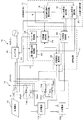
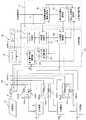
以下、本発明の実施の形態を説明する。図1は本発明の第1の実施の形態に係る太陽光発電装置の構成図である。この第1の実施の形態は、太陽電池11に2個の二次電池12a、12bが接続された場合を示している。
Embodiments of the present invention will be described below. FIG. 1 is a configuration diagram of a photovoltaic power generation apparatus according to the first embodiment of the present invention. This 1st Embodiment has shown the case where the two
すなわち、太陽電池11には並列に2個の二次電池12a、12bがスイッチ回路13a、13bを介して接続され直流系統14が形成されている。太陽電池11はダイオードDを介して直流系統14に接続され、直流系統14から太陽電池11への電力供給を阻止するようにしている。また、二次電池12a、12bの定格電圧Va、Vb(Va<Vb)は太陽電池11の開放電圧Voより小さく設定されている。そして、直流系統14はインバータ15を介して電力系統側の交流系統16に接続されている。
That is, two
二次電池選択部17は、太陽電池11に並列に接続する二次電池12a、12bを選択するものであり、太陽電池動作電圧判定部18と、第1二次電池選択部19と、第2二次電池選択部20とから構成されている。また、制御装置21は、インバータ15により太陽電池11を運転制御したり、二次電池選択部17により選択された二次電池12を充放電制御するものであり、二次電池接続部22と、最大電力追従制御部23と、充放電制御部24と、インバータ制御部25とから構成されている。
The secondary
まず、制御装置21について説明する。制御装置21の二次電池接続部22は、二次電池選択部17で選択された二次電池12a、12bをスイッチ回路13a、13bにより直流系統14の太陽電池11に並列に接続するものであり、充放電制御部24は、直流系統14の太陽電池11に並列に接続された二次電池12a、12bの充放電制御を行うものである。
First, the
最大電力追従制御部23は、二次電池12a、12bが直流系統14に接続されていないときは、直流系統14の電流Id及び電圧Vdを入力し、例えば、太陽電池11の現在の動作電圧から少しだけ電圧を増加減して、いわゆる山登り法で、出力電力が大きい動作電圧を探索し、太陽電池11の出力電力Pが最大電力Pmaxとなるように最大電力追従制御を行い、太陽電池11の出力電力Pが最大電力Pmaxとなる指令をインバータ制御部25に出力する。
When the
また、充放電制御部24は、二次電池12a、12bが直流系統14に接続されたときは、充放電制御部24は、二次電池12a、12bの定格電圧Va、Vbで定まる太陽電池11の出力電力Pとなる指令をインバータ制御部25に出力する。
In addition, when the
インバータ制御部25は、最大電力追従制御部23及び充放電制御部24からの指令に基づきインバータ15を制御する。これにより、二次電池12a、12bが直流系統14に接続されていないときは、インバータ15は太陽電池11の最大電力Pmaxを交流に変換して交流系統16に出力し、二次電池12a、12bが直流系統14に接続されたときは、二次電池12a、12bの定格電圧Va、Vbで定まる太陽電池11の出力電力Pを交流に変換して交流系統16に出力する。
The
次に、二次電池選択部17について説明する。二次電池選択部17は外部からの二次電池12a、12bの充放電指令Sにより起動される。外部からの充放電指令Sは、最大電力追従制御部23による最大電力追従制御中に二次電池12a、12bの充放電制御が必要となったときに、二次電池選択部17の太陽電池動作電圧判定部18に入力される。太陽電池動作電圧判定部18は外部からの充放電指令Sを入力すると、最大電力追従制御部23の最大電力追従制御による太陽電池11の動作電圧Vpと2個の二次電池12a、12bの定格電圧Va、Vbとの大小関係を判定する。太陽電池11の動作電圧Vpは直流系統14の電圧Vdとして検出する。
Next, the secondary
例えば、太陽電池11の動作電圧Vpが2個の二次電池12a、12bの定格電圧Va、Vbで定まる範囲の電圧(Va<Vp<Vb)であるか否かを判定する。以下、二次電池12aの定格電圧Vaと二次電池12bの定格電圧Vbとの間で定まる範囲の電圧(Va<Vp<Vb)を中間電圧範囲ということにする。太陽電池動作電圧判定部18での判定結果は第1二次電池選択部19及び第2二次電池選択部20に出力される。
For example, it is determined whether or not the operating voltage Vp of the
第1二次電池選択部19は、太陽電池動作電圧判定部18で太陽電池11の動作電圧Vpが2個の二次電池12a、12bの定格電圧Va、Vbの中間電圧範囲でない(Vp>Va、Vp>VbまたはVp<Va、Vp<Vb)と判定されたときは、太陽電池11の動作電圧Vpに近い定格電圧の二次電池12a、12bを選択し、選択した二次電池12a、12bを制御装置21の二次電池接続部22に通知する。これは、太陽電池11の動作電圧Vpは最大出力動作電圧であり、その最大出力動作電圧が2個の二次電池12a、12bの定格電圧Va、Vbの中間電圧範囲でないときは、最大出力動作電圧側に近い二次電池12の出力電力が大きくなるからである。
In the first secondary
例えば、太陽電池11の動作電圧Vpと2個の二次電池の定格電圧Va、Vbとの関係が、(Vp>Va、Vb)であるときは、Va<Vbであることから、太陽電池11の動作電圧Vpは定格電圧Vbに近いので、定格電圧Vbの二次電池12bを選択する。一方、太陽電池11の動作電圧Vpと2個の二次電池の定格電圧Va、Vbとの関係が、(Vp<Va、Vb)であるときは、Va<Vbであることから、太陽電池11の動作電圧Vpは定格電圧Vaに近いので、定格電圧Vaの二次電池12aを選択する。これにより、出力電力が大きい方の二次電池12を選択できる。
For example, when the relationship between the operating voltage Vp of the
なお、第1二次電池選択部19は太陽電池Vpの動作電圧Vpが二次電池の定格電圧Va、Vbと等しい(Vp=Va、Vp=Vb)と判定した場合には、その電圧を定格電圧とする二次電池12aまたは12bを選択し、選択した二次電池12a、12bを制御装置21の二次電池接続部22に通知する。
When the first secondary
次に、第2二次電池選択部20は、太陽電池動作電圧判定部18で太陽電池11の動作電圧Vpが2個の二次電池の定格電圧Va、Vbの中間電圧範囲である(Va<Vp<Vb)と判定されたときは、2個の二次電池12a、12bの定格電圧Va、Vbでそれぞれ太陽電池11を運転するように最大電力追従制御部23に指令を出力し、最大電力追従制御部23により定格電圧Va、Vbで太陽電池11が運転されたときの出力電力が大きい方の二次電池12a、12bを選択する。そして、その選択した二次電池12a、12bを制御装置21の二次電池接続部22に通知する。
Next, in the second secondary
制御装置21の二次電池接続部22は、第1二次電池選択部19または第2二次電池選択部20で選択された二次電池12a、12bの通知を受けると、充放電指令Sが充電指令か放電指令かを判断し、充放電指令Sが充電指令であるときはスイッチ回路13a、13bのスイッチング素子26a1、26b1によりその二次電池12a、12bを直流系統14の太陽電池11に並列に接続する。一方、充放電指令Sが放電指令であるときはスイッチ回路13a、13bのスイッチング素子26a2、26b2によりその二次電池12a、12bを直流系統14の太陽電池11に並列に接続する。そして、二次電池12a、12bを直流系統14に接続したことを充放電制御部24に通知する。
When the secondary
充放電制御部24は、二次電池接続部22から直流系統14に接続された二次電池12a、12bの情報を受信すると、その二次電池12a、12bに対し、外部からの充放電指令Sに従った指令をインバータ制御部25に出力する。これにより、インバータ制御部25はインバータ15により外部からの充放電指令Sに従った充放電制御を行う。
When the charge /
例えば、充放電指令Sが二次電池12a、12bの放電指令の場合には、二次電池12a、12bからの直流電力をインバータ15で交流に変換して交流系統16側に供給する。一方、充放電指令Sが二次電池12a、12bへの充電指令の場合には、交流系統16の交流電力をインバータ15で直流に変換して二次電池12a、12bに充電する。
For example, when the charge / discharge command S is a discharge command for the
このように、制御装置21は、二次電池12a、12bが直流系統14に接続されていないときは、太陽電池11の出力電力が最大電力となるように最大電力追従制御を行い、最大電力追従制御中に二次電池12a、12bの充放電制御が必要となったときは、第1二次電池選択部19または第2二次電池選択部20で選択された二次電池12a、12bを直流系統14の太陽電池11に並列に接続し、その二次電池の定格電圧Va、Vbで太陽電池11を運転するとともに、インバータ15により二次電池12a、12bの充放電制御を行う。
As described above, when the
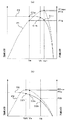
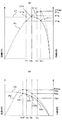
図2は、本発明の第1の実施の形態に係る太陽光発電装置の太陽電池11の動作電圧Vpが2個の二次電池の定格電圧Va、Vbの中間電圧範囲でない場合の太陽電池11のV−I特性及びV−P特性の一例を示すグラフであり、図2(a)は、日射強度が大きく太陽電池11の動作電圧Vpと2個の二次電池の定格電圧Va、Vbとの関係が(Vp>Va、Vb)である場合のV−I特性曲線C1及びV−P特性曲線P1の一例を示すグラフ、図2(b)は、日射強度が小さく太陽電池11の動作電圧Vpと2個の二次電池の定格電圧Va、Vbとの関係が(Vp<Va、Vb)である場合のV−I特性曲線C2及びV−P特性曲線P2の一例を示すグラフである。図2では、太陽電池11の温度を一定とした場合の日射強度をパラメータとしたV−I特性曲線及びV−P特性曲線を示している。
FIG. 2 shows the
図2(a)に示すように、日射強度が大きい場合には、V−I特性曲線C1上の座標C11のときに出力電力が最大となる最適動作点であり、太陽電池11は最大電力追従制御部23により、その動作点C11で運転しており、そのときの出力電力はV−P特性曲線P1の最大電力P1maxであり動作電圧はVp1である。
As shown in FIG. 2 (a), when the solar radiation intensity is high, this is the optimum operating point at which the output power is maximum at the coordinate C11 on the VI characteristic curve C1, and the
太陽電池11の動作電圧Vp1が2個の二次電池12a、12bの定格電圧Va、Vbの中間電圧範囲(Va<Vp1<Vb)でないので、第1二次電池選択部19は、太陽電池11の動作電圧Vp1に近い定格電圧Vbの二次電池12bを選択し、選択した二次電池12bを二次電池接続部22に通知する。これにより、太陽電池11は二次電池12bの定格電圧Vbで運転されることになり、そのときの動作点はC1bとなり、太陽電池11の出力電力PはP1bとなる。太陽電池11の出力電力P1bは、もう一方の二次電池12aの定格電圧Vaのときの動作点C1aでの出力電力P1aよりも大きい。従って、太陽電池11の発電能力を最大限に発揮させつつ、二次電池12bの運転も可能となる。
Since the operating voltage Vp1 of the
次に、図2(b)に示すように、日射強度が小さい場合には、V−I特性曲線C1上の座標C21のときに出力電力が最大となる最適動作点であり、太陽電池11は最大電力追従制御部23により、その動作点C21で運転しており、そのときの出力電力はV−P特性曲線P2の最大電力P2maxであり動作電圧はVp2である。
Next, as shown in FIG. 2 (b), when the solar radiation intensity is small, it is the optimum operating point at which the output power is maximum at the coordinate C21 on the VI characteristic curve C1, and the
太陽電池11の動作電圧Vp2が2個の二次電池の定格電圧Va、Vbの中間電圧範囲(Va<Vp2<Vb)でないので、第1二次電池選択部19は、太陽電池11の動作電圧Vp2に近い定格電圧Vaの二次電池12aを選択し、選択した二次電池12aを二次電池接続部22に通知する。これにより、太陽電池11は二次電池12aの定格電圧Vaで運転されることになり、そのときの動作点はC2aとなり、太陽電池11の出力電力PはP2aとなる。太陽電池11の出力電力P2aは、もう一方の二次電池12bの定格電圧Vbのときの動作点C2bでの出力電力P2bよりも大きい。従って、太陽電池11の発電能力を最大限に発揮させつつ、二次電池12aの運転も可能となる。
Since the operating voltage Vp2 of the
このように、太陽電池11の最大電力追従制御中に、二次電池12a、12bの充放電制御が必要となり、太陽電池11の動作電圧Vpが2個の二次電池の定格電圧Va、Vbの中間電圧範囲(Va<Vp<Vb)でないときは、太陽電池11の動作電圧Vpに近い定格電圧Va、Vbの二次電池12a、12bを選択するだけで、太陽電池11の発電能力を最大限に発揮させつつ太陽電池11に接続された二次電池12a、12bの充放電運転を行うことができる。つまり、いずれの二次電池12a、12bを選択するかの判断が容易に行える。
Thus, during the maximum power follow-up control of the
図3は、本発明の第1の実施の形態に係る太陽光発電装置の太陽電池11の動作電圧Vpが2個の二次電池の定格電圧Va、Vbの中間電圧範囲である場合の太陽電池11のV−I特性及びV−P特性の一例を示すグラフである。図3では、太陽電池11の温度を一定とした場合の日射強度をパラメータとしたV−I特性曲線及びV−P特性曲線を示しており、日射強度が図2(a)、図2(b)の中間である場合を示している。
FIG. 3 shows a solar cell in the case where the operating voltage Vp of the
図3に示すように、V−I特性曲線C3上の座標C31のときに出力電力が最大となる最適動作点であり、太陽電池11は最大電力追従制御部23により、その動作点C31で運転しており、そのときの出力電力はV−P特性曲線P3の最大電力P3maxであり動作電圧はVp3である。
As shown in FIG. 3, this is the optimum operating point at which the output power becomes maximum at the coordinate C31 on the VI characteristic curve C3, and the
第2二次電池選択部20は、太陽電池11の動作電圧Vp1が2個の二次電池の定格電圧Va、Vbの中間電圧範囲(Va<Vp3<Vb)であるので、2個の二次電池12a、12bの定格電圧Va、Vbでそれぞれ太陽電池11を運転するように最大電力追従制御部23に指令を出力する。そして、最大電力追従制御部23により定格電圧Va、Vbで太陽電池11が運転されたときの出力電力P3a、P3bを取得し、大きい方の二次電池12a、12bを選択する。つまり、定格電圧Vaでの動作点C3aの出力電力P3aと定格電圧Vbでの動作点C3bの出力電力P3bを取得し、図3では、出力電力P3aが出力電力P3bより大きいので、第2二次電池選択部20は二次電池12aを選択し、選択した二次電池12aを二次電池接続部22に通知する。
Since the operating voltage Vp1 of the
これにより、太陽電池11は二次電池12aの定格電圧Vaで運転されることになり、そのときの動作点はC3aとなり、太陽電池11の出力電力PはP3aとなる。太陽電池11の出力電力P3aは、もう一方の二次電池12bの定格電圧Vbのときの動作点C3bでの出力電力P3bよりも大きいので、太陽電池11の発電能力を最大限に発揮させつつ、二次電池12aの運転も可能となる。
As a result, the
このように、太陽電池11の最大電力追従制御中に、二次電池12a、12bの充放電制御が必要となり、太陽電池11の動作電圧Vpが2個の二次電池の定格電圧Va、Vbの中間電圧範囲(Va<Vp<Vb)であるときは、最大電力追従制御部23を起動して定格電圧Va、Vbで太陽電池11が運転されたときの出力電力P3a、P3bを取得し、大きい方の二次電池12a、12bを選択する。従って、太陽電池11の発電能力を最大限に発揮させつつ太陽電池11に接続された二次電池12a、12bの充放電運転を行うことができる。
Thus, during the maximum power follow-up control of the
以上の説明では、第2二次電池選択部20は、太陽電池11の動作電圧Vpが2個の二次電池の定格電圧Va、Vbの中間電圧範囲である場合には、最大電力追従制御部23を起動して定格電圧Va、Vbで太陽電池11が運転されたときの出力電力P3a、P3bを取得し、大きい方の二次電池12a、12bを選択するようにしたが、2個の二次電池12a、12bの定格電圧Va、Vbでそれぞれ太陽電池11を運転することに代えて、そのときの太陽電池11の動作電圧近傍の太陽電池11の出力電圧−出力電力特性(V−P特性)の近似曲線を演算し、その近似曲線に基づいて太陽電池11の動作電圧Vpを2個の二次電池の定格電圧としたときに出力電力Pが大きくなる方の二次電池12a、12bを選択するようにしてもよい。
In the above description, when the operating voltage Vp of the
図4は、本発明の第1の実施の形態に係る太陽光発電装置の太陽電池11の動作電圧Vpが2個の二次電池の定格電圧Va、Vbの中間電圧範囲である場合にV−P特性の近似曲線を用いて二次電池を選択する場合の説明図である。
FIG. 4 shows the case where the operating voltage Vp of the
図4に示すように、太陽電池11が動作点C31で運転しており、太陽電池11の動作電圧Vpが2個の二次電池の定格電圧Va、Vbの中間電圧範囲である場合には、第2二次電池選択部20は、最大電力追従制御部23から動作点C31の動作電圧Vp3及び動作電流Ip3を入力し、動作点C31の動作電圧Vp3及び動作電流Ip3に基づいて、動作電圧Vp3近傍の太陽電池11のV−P特性曲線P3の近似曲線P3’、P3”を演算する。近似曲線P3’は動作点C31の動作電圧Vp3より低い方向の近似曲線であり、近似曲線P3”は動作点C31の動作電圧Vp3より高い方向の近似曲線である。
As shown in FIG. 4, when the
一般に、V−P特性曲線Pは日射強度により変化する。日射強度が大きいときは図2(a)に示すV−P特性曲線P1となり、日射強度が小さいときは図2(b)に示すV−P特性曲線P2となる。また、日射強度が図2(a)、図2(b)の中間であるときは図4に示すような中間のV−P特性曲線P3となる。V−P特性曲線P3の動作点C31は最大出力P3maxであることから、動作点C31の動作電圧Vp3、動作電流Ip3が分かれば、動作点C31近傍の動作電圧Vp3より低い方向の近似曲線P3’、動作点C31近傍の動作電圧Vp3より高い方向の近似曲線P3”は容易に求めることができる。 Generally, the VP characteristic curve P varies depending on the solar radiation intensity. When the solar radiation intensity is high, the VP characteristic curve P1 shown in FIG. 2A is obtained, and when the solar radiation intensity is low, the VP characteristic curve P2 shown in FIG. 2B is obtained. Further, when the solar radiation intensity is intermediate between FIGS. 2A and 2B, an intermediate VP characteristic curve P3 as shown in FIG. 4 is obtained. Since the operating point C31 of the VP characteristic curve P3 is the maximum output P3max, if the operating voltage Vp3 and the operating current Ip3 at the operating point C31 are known, the approximate curve P3 ′ in the direction lower than the operating voltage Vp3 in the vicinity of the operating point C31. The approximate curve P3 ″ in the direction higher than the operating voltage Vp3 in the vicinity of the operating point C31 can be easily obtained.
そして、電圧近傍の太陽電池11のV−P特性曲線P3の近似曲線P3’、P3”から、太陽電池11の動作電圧Vpを2個の二次電池の定格電圧Va、Vbとしたときの出力電力P3a’、P3b”を求め、出力電力P3a’、P3b”のうち大きい方の二次電池12a、12bを選択する。図4の場合は、二次電池12aの出力電力P3a’が大きいので、二次電池12aを選択することになる。第2二次電池選択部20は、選択した二次電池12aを二次電池接続部22に通知する。
And the output when the operating voltage Vp of the
これにより、太陽電池11は二次電池12aの定格電圧Vaで運転されることになり、そのときの動作点はC3aとなり、太陽電池11の出力電力PはP3aとなる。従って、太陽電池11の発電能力を最大限に発揮させつつ、二次電池12bの運転も可能となる。この場合、二次電池12a、12bの選択は、最大電力追従制御部23による二次電池12a、12bの定格電圧Va、Vbでの運転によらずに、近似曲線P3’、P3”で求めるので、いずれの二次電池12a、12bを選択するかの判断を迅速に行うことができる。
As a result, the
第1の実施の形態によれば、太陽電池11の最大電力追従制御中に、二次電池12a、12bの充放電制御が必要となり、太陽電池11の動作電圧Vpが2個の二次電池の定格電圧Va、Vbの中間電圧範囲(Va<Vp<Vb)でないときは、太陽電池11の動作電圧Vpに近い定格電圧Va、Vbの二次電池12a、12bを選択し、太陽電池11の動作電圧Vpが2個の二次電池の定格電圧Va、Vbの中間電圧範囲(Va<Vp<Vb)であるときは、最大電力追従制御部23を起動して定格電圧Va、Vbで太陽電池11が運転されたときの出力電力P3a、P3bを取得し、大きい方の二次電池12a、12bを選択する。従って、太陽電池11の発電能力を最大限に発揮させつつ太陽電池11に接続された二次電池12a、12bの充放電運転を行うことができる。
According to the first embodiment, during the maximum power follow-up control of the
また、太陽電池11の動作電圧Vpが2個の二次電池の定格電圧Va、Vbの中間電圧範囲(Va<Vp<Vb)であるときに、最大電力追従制御部23による二次電池12a、12bの定格電圧Va、Vbでの運転によらずに、近似曲線P3’、P3”で求める場合には、二次電池12a、12bの選択を迅速に行うことができる。
Further, when the operating voltage Vp of the
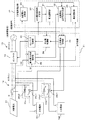
次に、本発明の第2の実施の形態を説明する。図5は本発明の第2の実施の形態に係る太陽光発電装置の構成図である。この第2の実施の形態は、図1に示した第1の実施の形態に対し、インバータ出力監視部27を追加して設け、インバータ出力監視部27は、二次電池12の運転中にインバータ15の出力電力が所定値以上変化した場合には、二次電池12を太陽電池11から切り離す指令を二次電池接続部22に出力するとともに、太陽電池動作電圧判定部18を起動するようにしたものである。そして、太陽電池動作電圧判定部18は起動がかけられると、太陽電池11の動作電圧Vpが中間電圧範囲(Va<Vp<Vb)であるか否かを判定し、第1二次電池選択部19または第2二次電池選択部20により、出力電力が大きい方の二次電池12a、12bを探索し直すようにしたものである。図1と同一要素には、同一符号を付し重複する説明は省略する。
Next, a second embodiment of the present invention will be described. FIG. 5 is a configuration diagram of a photovoltaic power generation apparatus according to the second embodiment of the present invention. In the second embodiment, an inverter
いま、二次電池12bが太陽電池11に並列に接続され、図6に示すように、V−I特性曲線C1の二次電池12bの定格電圧Vbの動作点C1bで運転されているとする。この場合の太陽電池11の出力電力Pは、V−P特性曲線P1で定まるP1bである。なお、動作点C11は太陽電池11の出力電力が最大となる最大出力P1maxの最適動作点である。
Now, it is assumed that the
この状態で、日照強度が変化しV−I特性曲線C1がV−I特性曲線C2に変化したとすると、太陽電池11の動作点は、V−I特性曲線C2の動作点C1bからV−I特性曲線C2の動作点C2bに変化する。従って、太陽電池11の出力電力PはV−P特性曲線P1で定まるP1bからV−P特性曲線P2で定まるP2bに変化する。
In this state, if the sunshine intensity is changed and the VI characteristic curve C1 is changed to the VI characteristic curve C2, the operating point of the
インバータ出力監視部27は、この出力電力Pの変化分ΔP(=P1b−P2b)を監視し、出力電力Pの変化分ΔPが所定値を超えたら、二次電池12bを太陽電池11から切り離す指令を二次電池接続部22に出力するとともに、二次電池選択部17の太陽電池動作電圧判定部18を起動する。
The inverter
二次電池接続部22により二次電池12bが直流系統14から切り離されると、最大電力追従制御部23により最大電力追従制御が行われ、太陽電池11の動作点は、V−I特性曲線C2の動作点C2bからV−I特性曲線C2の動作点C22に変化する。従って、太陽電池11の出力電力PはV−P特性曲線P2で定まるP2bからV−P特性曲線P2で定まるP2maxに変化する。
When the
太陽電池動作電圧判定部18は、変化したV−I特性曲線C2での動作電圧Vp(=Vp2)が中間電圧範囲(Va<Vp<Vb)にあるかどうかを判定し、第1二次電池選択部19または第2二次電池選択部20により、出力電力が大きい方の二次電池12a、12bを探索し直す。
The solar cell operating
これは、太陽電池11の出力電力Pが所定値以上変化した場合には、現在、接続している二次電池12bの定格電圧Vbにより、変化したV−I特性曲線C2で定まる動作点C2bでの出力電力P2bが、変化したV−I特性曲線C2で定まる最大出力P2maxに近いとは限らないからである。
This is because when the output power P of the
図6では、太陽電池11の動作電圧Vp(=Vp2)が中間電圧範囲(Va<Vp<Vb)にない場合を示している。太陽電池11の動作電圧Vp(=Vp2)が中間電圧範囲(Va<Vp<Vb)にないので、変化したV−I特性曲線C2で太陽電池11の出力電力Pが最大出力P2maxとなる動作点C22での動作電圧Vp2に近い定格電圧の二次電池12を探索し直すことになる。
FIG. 6 shows a case where the operating voltage Vp (= Vp2) of the
一方、太陽電池11の動作電圧Vpが中間電圧範囲(Va<Vp<Vb)であるときは、二次電池選択部17は第1の実施の形態の図3または図4で示した処理を行い、出力電力の大きい二次電池12を探索し直すことになる。
On the other hand, when the operating voltage Vp of the
第2の実施の形態によれば、二次電池12の運転中にインバータ15の出力電力Pが所定値以上変化した場合には、太陽電池11の最大出力の動作電圧Vpが変化したと推定し、現在接続している二次電池12を太陽電池11から切り離し、二次電池12a、12bを探索し直して太陽電池11の出力電力Pが最大出力付近で運転できる二次電池12a、12bのいずれかに切り替えるので、太陽電池11の最大出力の動作電圧Vが変化した場合でも、太陽電池11の出力電力の変動に合わせて太陽電池11を最大出力付近で運転できる。
According to the second embodiment, when the output power P of the
次に、本発明の第3の実施の形態を説明する。図7は本発明の第3の実施の形態に係る太陽光発電装置の構成図である。この第3の実施の形態は、図1に示した第1の実施の形態に対し、充電深度監視部28を追加して設け、充電深度監視部28は、2個の二次電池12a、12bの充電深度が所定範囲を逸脱した場合には2個の二次電池12a、12bの充電深度が均一化するように二次電池接続部22に接続切替指令を出力し、充放電制御部から要求があったときは2個の二次電池12a、12bの充電深度が均一化する充放電指令を出力するようにしたものである。図1と同一要素には、同一符号を付し重複する説明は省略する。
Next, a third embodiment of the present invention will be described. FIG. 7 is a configuration diagram of a photovoltaic power generation apparatus according to the third embodiment of the present invention. In the third embodiment, a charging
充電深度監視部28は、二次電池12a、12bの充電深度ca、cbを入力し、二次電池12a、12bの充電深度ca、cbが所定範囲(例えば、20%〜80%)を逸脱したかどうかを判断する。そして、二次電池12a、12bの充電深度ca、cbが所定範囲(20%〜80%)を逸脱したときは、接続切替指令を二次電池接続部22に出力する。例えば、二次電池12aの蓄電量が90%である場合には放電用の接続切替指令を出力し、二次電池12bの蓄電量が10%である場合には充電用の接続切替指令を出力する。
The charging
二次電池接続部22は、充電深度監視部28からの接続切替指令を入力するとその接続切替指令を記憶する。そして、二次電池接続部22は、第1二次電池選択部19または第2二次電池選択部20からの二次電池12a、12bの選択情報を待ち、第1二次電池選択部19または第2二次電池選択部20で選択された二次電池12a、12bを直流系統14の太陽電池11に並列に接続する。
When the secondary
いま、二次電池12aの蓄電量が90%であり、二次電池12bの蓄電量が10%であるとし、第1二次電池選択部19または第2二次電池選択部20で選択された二次電池が二次電池12aであるとする。この場合、二次電池12aの蓄電量が90%であることから、充電深度監視部28からの接続切替指令は放電用の接続切替指令である。従って、二次電池接続部22はスイッチ回路13aのスイッチング素子26a2をオンとした指令を出力する。これにより、二次電池12aは放電指令に対してのみ運転できることになる。
Now, the storage amount of the
一方、第1二次電池選択部19または第2二次電池選択部20で選択された二次電池が二次電池12bである場合には、二次電池12bの蓄電量が10%であることから、充電深度監視部28からの接続切替指令は充電用の接続切替指令である。従って、二次電池接続部22は、スイッチ回路13bのスイッチング素子26b1をオンとした指令を出力する。これにより、二次電池12bは充電指令に対してのみ運転できることになる。
On the other hand, when the secondary battery selected by the first secondary
充放電制御部24は、外部からの充放電指令Sが二次電池接続部22からの接続切替による充放電と一致するかどうかを判定する。充放電が一致するときは外部からの充放電指令に従って二次電池12a、12bに対して充放電制御を行う。
The charge /
一方、外部からの充放電指令Sが二次電池接続部22からの接続切替による充放電と一致しないときは、充放電制御部24は、充電深度監視部28に対して2個の二次電池12a、12bの充電深度が均一化する充放電指令を要求する。充電深度監視部28は充放電制御部24から充放電指令の要求を受けると、二次電池接続部22への接続指令と一致する充放電指令を出力する。これにより、充放電制御部24は外部からの充放電指令Sに代えて、充電深度監視部28からの充放電指令にて二次電池12a、12bに対して充放電制御を行う。つまり、2個の二次電池12a、12bの充電深度の均一化を優先した充放電制御を行う。
On the other hand, when the charge / discharge command S from the outside does not coincide with charge / discharge by connection switching from the secondary
充電深度監視部28からの充放電指令は、例えば、二次電池12aの蓄電量が90%であるとすると基準値の50%になるような放電指令であり、二次電池12bの蓄電量が10%であるとすると基準値の50%になるような充電指令である。充放電制御部24は、充電深度監視部28からの充放電指令に基づき充放電を行った結果、2個の二次電池12a、12bの充電深度が均一化すると、外部からの充放電指令Sに従った運転を行う。
The charge / discharge command from the charge
第3の実施の形態によれば、2個の二次電池12a、12bの充電深度を検出し、2個の二次電池12a、12bの充電深度が所定範囲を逸脱した場合には、充電深度が基準値になるように充放電制御を行うので、各二次電池12a、12bの充電深度が均一化する。
According to the third embodiment, when the charging depths of the two
図8は本発明の第4の実施の形態に係る太陽光発電装置の構成図である。この第4の実施の形態は、図1に示した第1の実施の形態に対し、太陽電池11の最大電力追従制御中に2個の二次電池12a、12bのいずれかを接続することに代えて、太陽電池11の起動時に2個の二次電池12a、12bのいずれかを接続するようにしたものである。この場合も、二次電池選択部17は、太陽電池11の出力電力が大きくなる方の二次電池12a、12bを選択することになる。図1と同一要素には同一符号を付し重複する説明は省略する。
FIG. 8 is a configuration diagram of a photovoltaic power generation apparatus according to the fourth embodiment of the present invention. In the fourth embodiment, one of the two
二次電池選択部17は、太陽電池11の起動時に太陽電池11の出力電力が大きくなる方の二次電池12a、12bを選択できるように構成されている。すなわち、二次電池選択部17は、太陽電池起動部29と、出力電力増方向判定部30と、暫定選択部31と、太陽電池出力電力判定部32と、最終選択部33とから構成されている。
The secondary
二次電池選択部17の太陽電池起動部29は、太陽電池11の起動指令が入力されると、最大電力追従制御部23を起動し、2個の二次電池12a、12bの定格電圧Va、Vbの中間電圧範囲で最大電力追従制御を開始させる。
When a start command for the
二次電池選択部17の出力電力増加方向判定部30は、太陽電池起動部29により起動された最大電力追従制御部23の最大電力追従制御により、太陽電池11の出力電力が増加した電圧方向を判定する。最大電力追従制御部23は、2個の二次電池12a、12bの定格電圧Va、Vbの中間電圧範囲で最大電力追従制御を開始するので、太陽電池11の出力電力は、最大電力追従制御の開始時点では必ずしも最大電力ではない。従って、最大電力追従制御部23で最大電力追従制御を開始して動作電圧を変化させると、出力電力が増加する電圧方向がある。出力電力増加方向判定部30は、そのときの出力電力が増加する電圧方向を検出するとともに、その増加した太陽電池11の出力電力を検出する。
The output power increase
二次電池選択部17の暫定選択部31は、出力電力増加方向判定部30で判定された電圧方向にある定格電圧の二次電池12を暫定的に選択し、二次電池接続部22にその選択した二次電池12の情報を通知する。
The
二次電池接続部22は、暫定選択部31で選択された二次電池12の通知を受けると、外部の充放電指令Sが充電指令か放電指令かを判断し、充放電指令に従ってスイッチ回路13のスイッチング素子26によりその二次電池12を直流系統14の太陽電池11に並列に接続する。例えば、暫定選択部31で選択された二次電池12が二次電池12bであり、充放電指令が放電指令であったときは、二次電池接続部22は、スイッチ回路13bのスイッチング素子26b2をオンし、二次電池12bを直流系統14の太陽電池11に並列に接続する。
When the secondary
以下の説明では、暫定選択部31で選択された二次電池12は二次電池12bであり外部からの充放電指令Sが放電指令である場合について説明する。
In the following description, the case where the secondary battery 12 selected by the
二次電池接続部22は、暫定選択部31で選択された二次電池12bを直流系統14に接続したことを充放電制御部24に通知する。これにより、充放電制御部24は、外部からの充放電指令Sに従った放電指令をインバータ制御部25に出力し放電制御を行う。
The secondary
次に、太陽電池出力電力判定部32は、暫定選択部31で選択された二次電池12bの定格電圧Vbでの太陽電池11の出力電力を最大電力追従制御部23から入力するとともに、出力電力増加方向判定部30から出力電力が増加する電圧方向を検出したときの太陽電池11の出力電力を入力する。
Next, the solar cell output
太陽電池11は二次電池12bが並列に接続されると、二次電池12bの定格電圧Vbでの運転となるので、太陽電池出力電力判定部32は、二次電池12bの定格電圧Vbでの太陽電池11の出力電力を入力し、出力電力増加方向判定部30で判定したときの出力電力より大きいか否かを判定する。そして、その判定結果を最終選択部33に出力する。
Since the
最終選択部33は、太陽電池出力電力判定部32の判定結果により、暫定選択部31で選択された二次電池12bの定格電圧Vbでの太陽電池11の出力電力が出力電力増加方向判定部30で判定したときの出力電力より大きいと判定されたときは、その二次電池12bを選択する。二次電池12bは既に直流系統14の太陽電池11に並列に接続されているので、そのままとする。この場合は、二次電池12の選択のための二次電池12の定格電圧での運転は1回で済む。
The
一方、太陽電池出力電力判定部32の判定結果により、暫定選択部31で選択された二次電池12bの定格電圧Vbでの太陽電池11の出力電力が出力電力増加方向判定部30で判定したときの出力電力より小さいと判定されたときは、最終選択部33は、二次電池12bに代えて他方の二次電池12aを直流系統14の太陽電池11に並列に接続するように二次電池接続部22に指令を出力する。
On the other hand, when the output power of the
これにより、二次電池接続部22はスイッチ回路13bのスイッチング素子26b2をオフするとともに、外部からの充放電指令Sが放電指令であるので、スイッチ回路13aのスイッチング素子26a2をオンする。このようにして、他方の二次電池12aを直流系統14の太陽電池11に並列に接続する。二次電池12aが直流系統14の太陽電池11に並列に接続されると、太陽電池11の動作電圧は二次電池12aの定格電圧Vaとなるので、太陽電池11の出力電力は、二次電池12aの定格電圧Vaでの出力電力となる。
As a result, the secondary
最終選択部33は、暫定選択部31で選択された二次電池12bの定格電圧Vbでの太陽電池11の出力電力と、他方の二次電池12aの定格電圧Vaでの太陽電池11の出力電力とを比較し、出力電力が大きい方の二次電池12を選択する。選択された二次電池12が二次電池12aである場合には、二次電池12aは直流系統14の太陽電池11に並列に接続されている状態であるので、そのままとする。一方、選択された二次電池12が二次電池12bである場合には、二次電池接続部22に二次電池12bへの接続切替指令を出力する。これにより、二次電池12aに代えて二次電池12bが直流系統14の太陽電池11に並列に接続される。この場合は、二次電池12の選択のための二次電池12の定格電圧での運転は2回必要となるが、必ず太陽電池11の出力電力が大きい方の二次電池12を選択できる。
The
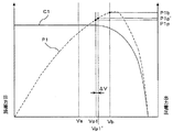
図9は本発明の第4の実施の形態に係る太陽光発電装置の動作の一例を示す太陽電池のV−I特性及びV−P特性のグラフである。図9では、太陽電池11の温度を一定とした場合の日射強度をパラメータとしたV−I特性曲線C1及びV−P特性曲線P1を示しており、二次電池12の選択のための二次電池12の定格電圧での運転が1回で済む場合を示している。
FIG. 9 is a graph of the VI characteristics and VP characteristics of a solar cell showing an example of the operation of the photovoltaic power generation apparatus according to the fourth embodiment of the present invention. FIG. 9 shows a VI characteristic curve C1 and a VP characteristic curve P1 using the solar radiation intensity when the temperature of the
太陽電池11の起動時には最大電力追従制御部23が起動され、図9に示すように、太陽電池11の動作電圧Vp1は、2個の二次電池12a、12bの定格電圧Va、Vbの中間電圧範囲で最大電力追従制御が開始される。このときの太陽電池11の出力電力はP1pである。最大電力追従制御の開始時点においては、太陽電池11の出力電力は必ずしも最大出力電力ではないので、出力電力が増加する電圧方向がある。
When the
図9では、動作電圧Vp1を正方向に微少電圧ΔVだけ移動させて動作電圧Vp1’とした場合を示している。この最大電力追従制御により動作電圧Vp1を正方向にΔVだけ変化させた動作電圧Vp1’では、太陽電池11の出力電力はP1p’となり、P1p’>P1pであるので、動作電圧Vp1を正方向に移動させたときには、太陽電池11の出力電力が増加していることが分かる。出力電力増加方向判定部30は、出力電力が増加する電圧方向(正方向)を検出するとともに、その増加した太陽電池11の出力電力P1p’を検出する。
FIG. 9 shows a case where the operating voltage Vp1 'is moved in the positive direction by a minute voltage ΔV to obtain the operating voltage Vp1'. In the operating voltage Vp1 ′ in which the operating voltage Vp1 is changed by ΔV in the positive direction by this maximum power tracking control, the output power of the
次に、暫定選択部31は、出力電力増加方向判定部30で判定された電圧方向(正方向)にある定格電圧Vbの二次電池12bを暫定的に選択する。そして、二次電池12bを直流系統14の太陽電池11に並列に接続して、太陽電池出力電力判定部32は、二次電池12bの定格電圧Vbでの太陽電池11の出力電力P1bを求め、最大電力追従制御の開始時の増加した出力電力P1p’より大きいか否かを判定する。図9では、P1b>P1p’である。
Next, the
最終選択部33は、二次電池12bの定格電圧Vbでの太陽電池11の出力電力P1bが最大電力追従制御の開始時の増加した出力電力P1p’より大きいので、その二次電池12bを選択する。二次電池12bは既に直流系統14の太陽電池11に並列に接続されているので、そのままとする。この場合は、最大電力追従制御部23で二次電池12bの定格電圧Vbで運転させるだけで、二次電池12bが求める二次電池であることが分かるので、二次電池12の選択のための二次電池12の定格電圧での運転は1回で済む。
The
図10は本発明の第4の実施の形態に係る太陽光発電装置の動作の他の一例を示す太陽電池のV−I特性及びV−P特性のグラフである。図10では、太陽電池11の温度を一定とした場合の日射強度をパラメータとしたV−I特性曲線C2及びV−P特性曲線P2を示しており、二次電池12の選択のための二次電池12の定格電圧での運転が2回必要な場合を示している。
FIG. 10 is a graph of the VI characteristics and VP characteristics of a solar cell showing another example of the operation of the photovoltaic power generation apparatus according to the fourth embodiment of the present invention. FIG. 10 shows a VI characteristic curve C2 and a VP characteristic curve P2 using the solar radiation intensity when the temperature of the
図9の場合と同様に、太陽電池11の起動時には、2個の二次電池12a、12bの定格電圧Va、Vbの中間電圧範囲Vp2で最大電力追従制御が開始される。このときの太陽電池11の出力電力はP2pである。
As in the case of FIG. 9, at the time of starting the
図9の場合と同様に、動作電圧Vp2を正方向に微少電圧ΔVだけ移動させて動作電圧Vp2’とした場合に、太陽電池11の出力電力はP2p’となり、Vp2’>Vp2であるので、動作電圧Vp2を正方向に移動させたときには、太陽電池11の出力電力が増加していることが分かる。出力電力増加方向判定部30は、出力電力が増加する電圧方向(正方向)を検出するとともに、その増加した太陽電池11の出力電力P2p’を検出する。
Similarly to the case of FIG. 9, when the operating voltage Vp2 is moved in the positive direction by a minute voltage ΔV to be the operating voltage Vp2 ′, the output power of the
次に、暫定選択部31は、出力電力増加方向判定部30で判定された電圧方向(正方向)にある定格電圧Vbの二次電池12bを暫定的に選択する。そして、二次電池12bを直流系統14の太陽電池11に並列に接続して、太陽電池出力電力判定部32は、二次電池12bの定格電圧Vbでの太陽電池11の出力電力P2bを求め、最大電力追従制御の開始時の増加した出力電力P2p’より大きいか否かを判定する。図10では、P2b<P2p’である。
Next, the
最終選択部33は、二次電池12bの定格電圧Vbでの太陽電池11の出力電力P2bが最大電力追従制御の開始時の増加した出力電力P2p’より小さいので、二次電池12bに代えて他方の二次電池12aを直流系統14の太陽電池11に並列に接続する。二次電池12aが直流系統14の太陽電池11に並列に接続されると、太陽電池11の動作電圧は二次電池12aの定格電圧Vaとなるので、太陽電池11の出力電力P2aは、二次電池12aの定格電圧Vaでの出力電力となる。
Since the output power P2b of the
最終選択部33は、暫定選択部31で選択された二次電池12bの定格電圧Vbでの太陽電池11の出力電力P2bと、他方の二次電池12aの定格電圧Vaでの太陽電池11の出力電力P2aとを比較する。図10の場合は、P2a>P2bであるので、最終選択部33は、出力電力P2aが大きい方の二次電池12aを選択する。選択された二次電池12aは直流系統14の太陽電池11に並列に接続されている状態であるので、そのままとする。
The
なお、P2a<P2bである場合には、二次電池12bを選択することになる。その場合には、選択された二次電池12が二次電池12bを、二次電池12aに代えて直流系統14の太陽電池11に並列に接続することになる。
When P2a <P2b, the
このように、暫定選択部31で選択された二次電池12bの定格電圧Vbでの太陽電池11の出力電力P2bが、他方の二次電池12aの定格電圧Vaでの太陽電池11の出力電力P2aより小さい場合には、二次電池12の選択のための二次電池12の定格電圧での運転は2回必要となるが、必ず太陽電池11の出力電力が大きい方の二次電池12を選択できる。
Thus, the output power P2b of the
第4の実施の形態では、太陽電池11の起動時に二次電池12a、12bのいずれかを接続する場合には、最大電力追従制御部23を起動し、2個の二次電池12a、12bの定格電圧Va、Vbの中間電圧範囲で最大電力追従制御を開始させ、最大電力追従制御により太陽電池11の出力電力が増加した電圧方向にある定格電圧の二次電池12を暫定的に選択する。そして、その二次電池12の定格電圧での太陽電池11の出力電力が電圧方向を判定したときの出力電力より大きいか否かを判定し大きいときは、その二次電池12を選択する。従って、二次電池12の選択のための二次電池12の定格電圧での運転は1回で済み、接続すべき二次電池12を迅速に判定できる。
In 4th Embodiment, when connecting either of the
一方、暫定的に選択した二次電池12の定格電圧での太陽電池11の出力電力が電圧方向を判定したときの出力電力より小さいときは、他方の二次電池12の定格電圧での太陽電池11の出力電力と比較する。そして、出力電力が大きい方の二次電池を選択する。従って、この場合は、二次電池12の選択のための二次電池の定格電圧での運転は2回となるが、必ず太陽電池11の出力電力が大きい方の二次電池を選択できる。
On the other hand, when the output power of the
以上の説明では、太陽電池11に2個の二次電池12a、12bが接続された場合について説明したが、3個以上の二次電池12a〜12nを接続し、二次電池12a〜12nのいずれかの充放電制御が必要となったときに、いずれかの二次電池12を選択して接続するようにすることも可能である。
In the above description, the case where the two
図11は本発明の第5の実施の形態に係る太陽光発電装置の構成図である。この第5の実施の形態は、複数個の二次電池12として、3個の二次電池12a、12b、12cが太陽電池11に接続された場合を示している。図1と同一要素には同一符号を付し重複する説明は省略する。
FIG. 11 is a configuration diagram of a photovoltaic power generation apparatus according to the fifth embodiment of the present invention. The fifth embodiment shows a case where three
図11に示すように、太陽電池11には並列に3個の二次電池12a、12b、12cがスイッチ回路13a、13b、13cを介して接続され直流系統14が形成されている。スイッチ回路13a、13b、13cは、充電用のスイッチング素子26a1、26b1、26c1と放電のスイッチング素子26a2、26b2、26c2を有し、二次電池接続部22は、二次電池12a、12b、12cに充電するときはスイッチング素子26a1、26b1、26c1をオンし、二次電池12a、12b、12cから放電するときはスイッチング素子26a2、26b2、26c2をオンして、二次電池12a、12b、12cを直流系統14に接続する。
As shown in FIG. 11, three
図12は、本発明の第5の実施の形態に係る太陽光発電装置の太陽電池11の動作電圧Vpが3個の二次電池12a、12b、12cの定格電圧Va、Vb、Vcの中間電圧範囲でない場合の太陽電池11のV−I特性及びV−P特性の一例を示すグラフであり、図12(a)は、日射強度が大きく太陽電池11の動作電圧Vpと3個の二次電池12a、12b、12cの定格電圧Va、Vb、Vcとの関係が(Vp>Va、Vb、Vc)である場合のV−I特性曲線C1及びV−P特性曲線P1の一例を示すグラフ、図12(b)は、日射強度が小さく太陽電池11の動作電圧Vpと3個の二次電池12a、12b、12cの定格電圧Va、Vb、Vcとの関係が(Vp<Va、Vb、Vc)である場合のV−I特性曲線C2及びV−P特性曲線P2の一例を示すグラフである。図12では、太陽電池11の温度を一定とした場合の日射強度をパラメータとしたV−I特性曲線及びV−P特性曲線を示している。
FIG. 12 shows an intermediate voltage between the rated voltages Va, Vb, and Vc of the three
ここで、中間電圧範囲は、太陽電池11の動作電圧Vpが3個以上の二次電池12〜12nの定格電圧Va〜Vnのうちの最小値以上で最大値以下である電圧範囲を中間電圧範囲をいうこととする。従って、二次電池12が3個の場合には、3個の二次電池12a、12b、12cの定格電圧Va、Vb、Vcのうちの最小値以上で最大値以下である電圧範囲を中間電圧範囲をいうことになる。
Here, the intermediate voltage range is a voltage range in which the operating voltage Vp of the
図12(a)に示すように、日射強度が大きい場合には、V−I特性曲線C1上の座標C11のときに出力電力が最大となる最適動作点であり、太陽電池11は最大電力追従制御部23により、その動作点C11で運転しており、そのときの出力電力はV−P特性曲線P1の最大電力P1maxであり動作電圧はVp1である。
As shown in FIG. 12 (a), when the solar radiation intensity is high, this is the optimum operating point at which the output power becomes maximum at the coordinate C11 on the VI characteristic curve C1, and the
太陽電池11の動作電圧Vp1が3個の二次電池12a、12b、12cの定格電圧Va、Vb、Vcが(Va<Vb<Vc)であり、太陽電池11の動作電圧Vp1が二次電池12cの定格電圧Vcより大きく、中間電圧範囲(Va<Vp1<Vc)でない場合には、第1二次電池選択部19は、太陽電池11の動作電圧Vp1に最も近い定格電圧Vcの二次電池12cを選択し、選択した二次電池12cを二次電池接続部22に通知する。
The operating voltage Vp1 of the
これにより、太陽電池11は二次電池12cの定格電圧Vcで運転されることになり、そのときの動作点はC1cとなり、太陽電池11の出力電力PはP1cとなる。太陽電池11の出力電力P1cは、残りの二次電池12a、12bの定格電圧Va、Vbのときの動作点C1a、C1bでの出力電力P1a、P1bよりも大きい。従って、太陽電池11の発電能力を最大限に発揮させつつ、二次電池12cの運転も可能となる。
Thereby, the
次に、図12(b)に示すように、日射強度が小さい場合には、V−I特性曲線C1上の座標C21のときに出力電力が最大となる最適動作点であり、太陽電池11は最大電力追従制御部23により、その動作点C21で運転しており、そのときの出力電力はV−P特性曲線P2の最大電力P2maxであり動作電圧はVp2である。
Next, as shown in FIG. 12B, when the solar radiation intensity is small, the output power is the optimum operating point at the coordinate C21 on the VI characteristic curve C1, and the
太陽電池11の動作電圧Vp2が3個の二次電池の定格電圧Va、Vb、Vcの中間電圧範囲(Va<Vp2<Vc)でないので、第1二次電池選択部19は、太陽電池11の動作電圧Vp2に最も近い定格電圧Vaの二次電池12aを選択し、選択した二次電池12aを二次電池接続部22に通知する。
Since the operating voltage Vp2 of the
これにより、太陽電池11は二次電池12aの定格電圧Vaで運転されることになり、そのときの動作点はC2aとなり、太陽電池11の出力電力PはP2aとなる。太陽電池11の出力電力P2aは、残りの二次電池12b、12cの定格電圧Vb、Vcのときの動作点C2b、C2cでの出力電力P2b、P2cよりも大きい。従って、太陽電池11の発電能力を最大限に発揮させつつ、二次電池12aの運転も可能となる。
Thus, the
このように、太陽電池11の最大電力追従制御中に、3個の二次電池12a、12b、12cのいずれかに充放電制御が必要となり、太陽電池11の動作電圧Vpが3個の二次電池12a、12b、12cの定格電圧Va、Vb、Vcの中間電圧範囲(Va<Vp<Vc)でないときは、太陽電池11の動作電圧Vpに近い定格電圧の二次電池12を選択するだけで、太陽電池11の発電能力を最大限に発揮させつつ太陽電池11に接続された二次電池12a、12b、12cの充放電運転を行うことができる。つまり、いずれの二次電池12a、12b、12cを選択するかの判断が容易に行える。
Thus, during the maximum power tracking control of the
図13は、本発明の第5の実施の形態に係る太陽光発電装置の太陽電池11の動作電圧Vpが3個の二次電池12a、12b、12cの定格電圧Va、Vb、Vcの中間電圧範囲(定格電圧Va<Vp<VcのうちのVa<Vp<Vb)である場合の太陽電池11のV−I特性及びV−P特性の一例を示すグラフである。図13では、太陽電池11の温度を一定とした場合の日射強度をパラメータとしたV−I特性曲線及びV−P特性曲線を示しており、日射強度が図12(a)、図12(b)の中間である場合を示している。
FIG. 13 shows an intermediate voltage between the rated voltages Va, Vb, and Vc of the three
図13に示すように、V−I特性曲線C3上の座標C31のときに出力電力が最大となる最適動作点であり、太陽電池11は最大電力追従制御部23により、その動作点C31で運転しており、そのときの出力電力はV−P特性曲線P3の最大電力P3maxであり動作電圧はVp3である。
As shown in FIG. 13, it is the optimum operating point at which the output power becomes maximum at the coordinate C31 on the VI characteristic curve C3, and the
第2二次電池選択部20は、太陽電池11の動作電圧Vp3が中間電圧範囲(Va<Vp<Vc)のうちの二次電池12a、12bの定格電圧Va、Vbの間であり、太陽電池11の動作電圧Vp3は二次電池12a、12bの定格電圧Va、Vbで挟まれた動作電圧範囲にあるので、その2個の二次電池12a、12bの定格電圧Va、Vbでそれぞれ太陽電池11を運転するように最大電力追従制御部23に指令を出力する。
The second secondary
そして、最大電力追従制御部23により定格電圧Va、Vbで太陽電池11が運転されたときの出力電力P3a、P3bを取得し、大きい方の二次電池12a、12bを一時的に選択する。図13の場合には、二次電池12bの出力電力P3bが二次電池12aの出力電力P3aより大きいので、第2二次電池選択部20は二次電池12bを一時的に選択する。そして、その一時的に選択した二次電池12bの定格電圧Vbの動作電圧範囲の外側にある二次電池12の定格電圧での太陽電池11の出力電力Pを求め、一時的に選択した二次電池12bを含めて太陽電池11の出力電力Pが最大出力となる二次電池12を選択する。
And the output power P3a, P3b when the
つまり、定格電圧Vaでの動作点C3aの出力電力P3aと定格電圧Vbでの動作点C3bの出力電力P3bを取得し、図13では、出力電力P3bが出力電力P3aより大きいので、第2二次電池選択部20は二次電池12bを一時的に選択し、さらに、一時的に選択した二次電池12bの定格電圧Vbの動作電圧範囲の外側にある二次電池12cの定格電圧Vcでの太陽電池11の出力電力P3cを求め、一時的に選択した二次電池12bを含めて太陽電池11の出力電力Pが最大出力となる二次電池12bを選択することになる。選択した二次電池12bを二次電池接続部22に通知する。
That is, the output power P3a at the operating point C3a at the rated voltage Va and the output power P3b at the operating point C3b at the rated voltage Vb are acquired. In FIG. 13, the output power P3b is larger than the output power P3a. The
これにより、太陽電池11は二次電池12bの定格電圧Vbで運転されることになり、そのときの動作点はC3bとなり、太陽電池11の出力電力PはP3bとなる。太陽電池11の出力電力P3bは、残りの二次電池12a、12cの定格電圧Va、Vcのときの動作点C3a、C3cでの出力電力P3a、P3cよりも大きいので、太陽電池11の発電能力を最大限に発揮させつつ、二次電池12bの運転も可能となる。
Thus, the
このように、太陽電池11の最大電力追従制御中に、二次電池12a、12b、12cの充放電制御が必要となり、太陽電池11の動作電圧Vpが3個の二次電池の定格電圧Va、Vb、Vcの中間電圧範囲(Va<Vp<Vc)であるときは、第2二次電池選択部20は、太陽電池11の動作電圧Vpが中間電圧範囲(Va<Vp<Vc)内でいずれか2個のどの定格電圧で挟まれた動作電圧範囲にあるかを判定し、最大電力追従制御部23により、その動作電圧範囲を形成した2個の二次電池12の定格電圧でそれぞれ太陽電池11を運転し、そのときの出力電力が大きい方の二次電池を一時的に選択し、一時的に選択した二次電池12の定格電圧の動作電圧範囲の外側にある二次電池12の定格電圧での太陽電池11の出力電力Pを求め、一時的に選択した二次電池12を含めて太陽電池11の出力電力Pが最大出力となる二次電池12を選択する。従って、太陽電池11の発電能力を最大限に発揮させつつ太陽電池11に接続された二次電池12a、12b、12cの充放電運転を行うことができる。
Thus, during the maximum power follow-up control of the
以上の説明では、第2二次電池選択部20は、太陽電池11の動作電圧Vpが中間電圧範囲(Va<Vp<Vc)内の2個の二次電池12の定格電圧に挟まれた動作電圧範囲のときは、太陽電池11の動作電圧Vpを挟んだ動作電圧範囲を形成する2個の二次電池12の定格電圧でそれぞれ太陽電池11を運転するようにしたが、それに代えて、そのときの太陽電池11の動作電圧Vp近傍の太陽電池11の出力電圧−出力電力特性(V−P特性)の近似曲線を演算し、その近似曲線に基づいて出力電力Pが大きい二次電池12を選択するようにしてもよい。
In the above description, the second secondary
図14は、本発明の第5の実施の形態に係る太陽光発電装置の太陽電池11の動作電圧Vpが中間電圧範囲(Va<Vp<Vc)内の2個の二次電池12a、12bの定格電圧Va、Vbに挟まれた動作電圧範囲のときにV−P特性の近似曲線を用いて二次電池を選択する場合の説明図である。
FIG. 14 shows the operation of the two
図14に示すように、太陽電池11が動作点C31で運転しており、太陽電池11の動作電圧Vpが2個の二次電池の定格電圧Va、Vbの中間電圧範囲である場合には、第2二次電池選択部20は、最大電力追従制御部23から動作点C31の動作電圧Vp3及び動作電流Ip3を入力し、動作点C31の動作電圧Vp3及び動作電流Ip3に基づいて、動作電圧Vp3近傍の太陽電池11のV−P特性曲線P3の近似曲線P3’、P3”を演算する。近似曲線P3’は動作点C31の動作電圧Vp3より低い方向の近似曲線であり、近似曲線P3”は動作点C31の動作電圧Vp3より高い方向の近似曲線である。
As shown in FIG. 14, when the
一般に、V−P特性曲線Pは日射強度により変化する。日射強度が大きいときは図12(a)に示すV−P特性曲線P1となり、日射強度が小さいときは図12(b)に示すV−P特性曲線P2となる。また、日射強度が図12(a)、図12(b)の中間であるときは図14に示すような中間のV−P特性曲線P3となる。V−P特性曲線P3の動作点C31は最大出力P3maxであることから、動作点C31の動作電圧Vp3、動作電流Ip3が分かれば、動作点C31近傍の動作電圧Vp3より低い方向の近似曲線P3’、動作点C31近傍の動作電圧Vp3より高い方向の近似曲線P3”は容易に求めることができる。 Generally, the VP characteristic curve P varies depending on the solar radiation intensity. When the solar radiation intensity is high, a VP characteristic curve P1 shown in FIG. 12A is obtained, and when the solar radiation intensity is low, a VP characteristic curve P2 shown in FIG. 12B is obtained. Further, when the solar radiation intensity is intermediate between FIGS. 12A and 12B, an intermediate VP characteristic curve P3 as shown in FIG. 14 is obtained. Since the operating point C31 of the VP characteristic curve P3 is the maximum output P3max, if the operating voltage Vp3 and the operating current Ip3 at the operating point C31 are known, the approximate curve P3 ′ in the direction lower than the operating voltage Vp3 in the vicinity of the operating point C31. The approximate curve P3 ″ in the direction higher than the operating voltage Vp3 in the vicinity of the operating point C31 can be easily obtained.
そして、電圧近傍の太陽電池11のV−P特性曲線P3の近似曲線P3’、P3”から、太陽電池11の動作電圧Vpを2個の二次電池の定格電圧Va、Vbとしたときの出力電力P3a’、P3b”を求め、出力電力P3a’、P3b”のうち大きい方の二次電池12a、12bを一時的に選択する。
And the output when the operating voltage Vp of the
図14の場合は、二次電池12bの出力電力P3b”が大きいので、二次電池12bを一時的に選択する。そして、その一時的に選択した二次電池12bの定格電圧Vbの動作電圧範囲の外側にある二次電池12cの定格電圧Vcでの太陽電池11の出力電力P3c”を求め、一時的に選択した二次電池12bを含めて太陽電池11の出力電力Pが最大出力となる二次電池12を選択する。図14では、P3b”>P3c”であるので、第2二次電池選択部20は、二次電池12bを選択し、その選択した二次電池12bを二次電池接続部22に通知する。
In the case of FIG. 14, since the output power P3b ″ of the
これにより、太陽電池11は二次電池12bの定格電圧Vbで運転されることになり、そのときの動作点はC3bとなり、太陽電池11の出力電力PはP3bとなる。従って、太陽電池11の発電能力を最大限に発揮させつつ、二次電池12bの運転も可能となる。この場合、二次電池12a、12bの選択は、最大電力追従制御部23による二次電池12a、12bの定格電圧Va、Vbでの運転によらずに、近似曲線P3’、P3”で求めるので、いずれの二次電池12a、12bを選択するかの判断を迅速に行うことができる。
Thus, the
第5の実施の形態によれば、太陽電池11の最大電力追従制御中に、太陽電池11に接続された二次電池12a、12b、12cの充放電制御が必要となり、太陽電池11の動作電圧Vpが中間電圧範囲(Va<Vp<Vc)でないときは、太陽電池11の動作電圧Vpに近い定格電圧の二次電池12を選択し、太陽電池11の動作電圧Vpが中間電圧範囲(Va<Vp<Vc)内の2個の二次電池12の定格電圧に挟まれた動作電圧範囲のときは、最大電力追従制御部23を起動して動作電圧範囲を形成する2個の二次電池12の定格電圧で太陽電池11が運転されたときの出力電力Pを一時的に選択し、一時的に選択した二次電池12の定格電圧の動作電圧範囲の外側にある二次電池12の定格電圧での太陽電池11の出力電力Pを求め、一時的に選択した二次電池12を含めて太陽電池11の出力電力Pが最大出力となる二次電池12を選択する。従って、太陽電池11の発電能力を最大限に発揮させつつ、太陽電池11に接続された二次電池12a、12b、12cの充放電運転を行うことができる。
According to the fifth embodiment, during the maximum power follow-up control of the
次に、本発明の第6の実施の形態を説明する。図15は本発明の第6の実施の形態に係る太陽光発電装置の構成図である。この第6の実施の形態は、図11に示した第5の実施の形態に対し、インバータ出力監視部27を追加して設け、インバータ出力監視部27は、二次電池12の運転中にインバータ15の出力電力が所定値以上変化した場合には、二次電池12を太陽電池11から切り離す指令を二次電池接続部22に出力するとともに、太陽電池動作電圧判定部18を起動するようにしたものである。そして、太陽電池動作電圧判定部18は起動がかけられると、太陽電池11の動作電圧Vpが中間電圧範囲(Va<Vp<Vc)であるか否かを判定し、第1二次電池選択部19または第2二次電池選択部20により、出力電力が大きい二次電池12を探索し直すようにしたものである。図11と同一要素には、同一符号を付し重複する説明は省略する。
Next, a sixth embodiment of the present invention will be described. FIG. 15: is a block diagram of the solar power generation device which concerns on the 6th Embodiment of this invention. In the sixth embodiment, an inverter
いま、二次電池12cが太陽電池11に並列に接続され、図16に示すように、V−I特性曲線C1の二次電池12cの定格電圧Vcの動作点C1cで運転されているとする。この場合の太陽電池11の出力電力Pは、V−P特性曲線P1で定まるP1cである。なお、動作点C11は太陽電池11の出力電力が最大となる最大出力P1maxの最適動作点である。
Now, it is assumed that the
この状態で、日照強度が変化しV−I特性曲線C1がV−I特性曲線C2に変化したとすると、太陽電池11の動作点は、V−I特性曲線C2の動作点C1cからV−I特性曲線C2の動作点C2cに変化する。従って、太陽電池11の出力電力PはV−P特性曲線P1で定まるP1cからV−P特性曲線P2で定まるP2cに変化する。
In this state, if the sunshine intensity is changed and the VI characteristic curve C1 is changed to the VI characteristic curve C2, the operating point of the
インバータ出力監視部27は、この出力電力Pの変化分ΔP(=P1b−P2c)を監視し、出力電力Pの変化分ΔPが所定値を超えたら、二次電池12cを太陽電池11から切り離す指令を二次電池接続部22に出力するとともに、二次電池選択部17の太陽電池動作電圧判定部18を起動する。
The inverter
二次電池接続部22により二次電池12cが直流系統14から切り離されると、最大電力追従制御部23により最大電力追従制御が行われ、太陽電池11の動作点は、V−I特性曲線C2の動作点C2cからV−I特性曲線C2の動作点C22に変化する。従って、太陽電池11の出力電力PはV−P特性曲線P2で定まるP2cからV−P特性曲線P2で定まるP2maxに変化する。
When the
太陽電池動作電圧判定部18は、変化したV−I特性曲線C2での動作電圧Vp(=Vp2)が中間電圧範囲(Va<Vp<Vc)にあるかどうかを判定し、第1二次電池選択部19または第2二次電池選択部20により、出力電力が大きい二次電池12a、12b、12cを探索し直す。
The solar cell operating
これは、太陽電池11の出力電力Pが所定値以上変化した場合には、現在、接続している二次電池12cの定格電圧Vcにより、変化したV−I特性曲線C2で定まる動作点C2cでの出力電力P2cが、変化したV−I特性曲線C2で定まる最大出力P2maxに近いとは限らないからである。
This is because when the output power P of the
図16では、太陽電池11の動作電圧Vp(=Vp2)が中間電圧範囲(Va<Vp<Vc)にない場合を示している。太陽電池11の動作電圧Vp(=Vp2)が中間電圧範囲(Va<Vp<Vc)にないので、変化したV−I特性曲線C2で太陽電池11の出力電力Pが最大出力P2maxとなる動作点C22での動作電圧Vp2に近い定格電圧の二次電池12を探索し直すことになる。
FIG. 16 shows a case where the operating voltage Vp (= Vp2) of the
一方、太陽電池11の動作電圧Vpが中間電圧範囲(Va<Vp<Vc)であるときは、二次電池選択部17は第1の実施の形態の図13または図14で示した処理を行い、出力電力の大きい二次電池12を探索し直すことになる。
On the other hand, when the operating voltage Vp of the
次に、本発明の第7の実施の形態を説明する。図17は本発明の第7の実施の形態に係る太陽光発電装置の構成図である。この第7の実施の形態は、図11に示した第5の実施の形態に対し、充電深度監視部28を追加して設け、充電深度監視部28は、3個の二次電池12a、12b、12cの充電深度が所定範囲を逸脱した場合には3個の二次電池12a、12b、12cの充電深度が均一化するように二次電池接続部22に接続切替指令を出力し、充放電制御部24から要求があったときは2個の二次電池12a、12b、12cの充電深度が均一化する充放電指令を出力するようにしたものである。図11と同一要素には、同一符号を付し重複する説明は省略する。
Next, a seventh embodiment of the present invention will be described. FIG. 17 is a configuration diagram of a photovoltaic power generation apparatus according to the seventh embodiment of the present invention. In the seventh embodiment, a charging
充電深度監視部28は、二次電池12a、12b、12cの充電深度ca、cb、ccを入力し、二次電池12a、12b、12cの充電深度ca、cb、ccが所定範囲(例えば、20%〜80%)を逸脱したかどうかを判断する。そして、二次電池12a、12b、12cの充電深度ca、cb、ccが所定範囲(20%〜80%)を逸脱したときは、接続切替指令を二次電池接続部22に出力する。なお、二次電池12a、12b、12cの充電深度ca、cb、ccが所定範囲(20%〜80%)を逸脱していないときは、接続切替指令は出力されない。
The charging
いま、二次電池12aの蓄電量が90%であり、二次電池12bの蓄電量が10%であり、二次電池12cの蓄電量が50%であるとする。そうすると、二次電池12aの充電深度caは所定範囲(20%〜80%)を大きい方に逸脱しているので、充電深度監視部28は、二次電池接続部22に対し、二次電池12aの放電用の接続切替指令を出力する。一方、二次電池12bの充電深度cbは所定範囲(20%〜80%)を小さい方に逸脱しているので、充電深度監視部28は、二次電池接続部22に対し、二次電池12bの充電用の接続切替指令を出力する。また、二次電池12cの充電深度ccは所定範囲(20%〜80%)内にあるので、充電深度監視部28は、二次電池接続部22に対して二次電池12cの接続切替指令は出力しない。二次電池接続部22は、充電深度監視部28からの接続切替指令を入力するとその接続切替指令を記憶する。
Now, it is assumed that the storage amount of the
そして、二次電池接続部22は、第1二次電池選択部19または第2二次電池選択部20からの二次電池12a、12b、12cの選択情報を待ち、第1二次電池選択部19または第2二次電池選択部20で選択された二次電池12が充電深度監視部28から接続切替指令のあった二次電池12に一致するかどうかを判断する。
The secondary
第1二次電池選択部19または第2二次電池選択部20で選択された二次電池12が充電深度監視部28から接続切替指令のあった二次電池12に一致しない場合には、二次電池接続部22は、第1二次電池選択部19または第2二次電池選択部20で選択された二次電池12を直流系統14に接続する。その際には、外部からの充放電指令Sの内容に従ってスイッチ回路13のスイッチング素子26a、26bのいずれかをオンすることになる。
If the secondary battery 12 selected by the first secondary
一方、第1二次電池選択部19または第2二次電池選択部20で選択された二次電池12が充電深度監視部28から接続切替指令のあった二次電池12に一致する場合には、その接続切替指令通りに、二次電池12を直流系統14に接続する。例えば、第1二次電池選択部19または第2二次電池選択部20で選択された二次電池が二次電池12aである場合には、二次電池12aの蓄電量が90%であることから、充電深度監視部28からの接続切替指令は放電用の接続切替指令であるので、二次電池接続部22はスイッチ回路13aのスイッチング素子26a2をオンとした指令を出力する。これにより、二次電池12aは放電指令に対してのみ運転できることになる。
On the other hand, when the secondary battery 12 selected by the first secondary
一方、第1二次電池選択部19または第2二次電池選択部20で選択された二次電池が二次電池12bである場合には、二次電池12bの蓄電量が10%であることから、充電深度監視部28からの接続切替指令は充電用の接続切替指令であるので、二次電池接続部22は、スイッチ回路13bのスイッチング素子26b1をオンとした指令を出力する。これにより、二次電池12bは充電指令に対してのみ運転できることになる。
On the other hand, when the secondary battery selected by the first secondary
次に、充放電制御部24は、外部からの充放電指令Sが二次電池接続部22からの接続切替による充放電と一致するかどうかを判定する。充放電が一致するときは外部からの充放電指令に従って二次電池12a、12bに対して充放電制御を行う。
Next, the charge /
一方、外部からの充放電指令Sが二次電池接続部22からの接続切替による充放電と一致しないときは、充放電制御部24は、充電深度監視部28に対して二次電池12a、12bの充電深度が均一化する充放電指令を要求する。充電深度監視部28は充放電制御部24から充放電指令の要求を受けると、二次電池接続部22への接続指令と一致する充放電指令を出力する。これにより、充放電制御部24は外部からの充放電指令Sに代えて、充電深度監視部28からの充放電指令にて二次電池12に対して充放電制御を行う。つまり、二次電池12の充電深度の均一化を優先した充放電制御を行う。
On the other hand, when the charge / discharge command S from the outside does not coincide with charge / discharge by connection switching from the secondary
充電深度監視部28からの充放電指令は、例えば、二次電池12aの蓄電量が90%であるとすると基準値の50%になるような放電指令であり、二次電池12bの蓄電量が10%であるとすると基準値の50%になるような充電指令である。充放電制御部24は、充電深度監視部28からの充放電指令に基づき充放電を行った結果、2個の二次電池12a、12bの充電深度が均一化すると、外部からの充放電指令Sに従った運転を行う。
The charge / discharge command from the charge
第7の実施の形態によれば、3個の二次電池12a、12b、12cの充電深度を検出し、いずれかの二次電池12a、12b、12cの充電深度が所定範囲を逸脱した場合には、充電深度が基準値になるように充放電制御を行うので、各二次電池12a、12b、12cの充電深度が均一化する。
According to the seventh embodiment, when the charging depth of the three
次に、本発明の第8の実施の形態を説明する。図18は本発明の第8の実施の形態に係る太陽光発電装置の構成図である。この第8の実施の形態は、図11に示した第5の実施の形態に対し、太陽電池11の最大電力追従制御中に3個の二次電池12a、12b、12cのいずれかを接続することに代えて、太陽電池11の起動時に3個の二次電池12a、12b、12cのいずれかを接続するようにしたものである。この場合も、二次電池選択部17は、太陽電池11の出力電力が大きくなるいずれかの二次電池12a、12b、12cを選択することになる。図11と同一要素には同一符号を付し重複する説明は省略する。
Next, an eighth embodiment of the present invention will be described. FIG. 18 is a configuration diagram of a photovoltaic power generation apparatus according to the eighth embodiment of the present invention. In the eighth embodiment, any one of the three
二次電池選択部17は、太陽電池11の起動時に太陽電池11の出力電力が大きくなる二次電池12a、12b、12cを選択できるように構成されている。すなわち、二次電池選択部17は、太陽電池起動部29と、出力電力増方向判定部30と、暫定選択部31と、太陽電池出力電力判定部32と、最終選択部33とから構成されている。
The secondary
二次電池選択部17の太陽電池起動部29は、太陽電池11の起動時に最大電力追従制御部23を起動し、その際の太陽電池11の動作電圧Vpを中間電圧範囲(Va<Vp<Vc)として最大電力追従制御を開始させる。
The solar
二次電池選択部17の出力電力増加方向判定部30は、太陽電池起動部29により起動された最大電力追従制御部23の最大電力追従制御により、太陽電池11の出力電力が増加した電圧方向を判定する。
The output power increase
最大電力追従制御部23は、中間電圧範囲(Va<Vp<Vc)で最大電力追従制御を開始するので、太陽電池11の出力電力は、最大電力追従制御の開始時点では必ずしも最大電力ではない。従って、最大電力追従制御部23で最大電力追従制御を開始して動作電圧を変化させると、出力電力が増加する電圧方向がある。出力電力増加方向判定部30は、そのときの出力電力が増加する電圧方向を検出するとともに、その増加した太陽電池11の出力電力を検出する。
Since the maximum power
二次電池選択部17の暫定選択部31は、出力電力増加方向判定部30で判定された電圧方向に定格電圧がある二次電池12のうち、その定格電圧での太陽電池の出力電力が最大出力となる二次電池12を暫定的に選択する二次電池接続部22にその選択した二次電池12の情報を通知する。
The
二次電池接続部22は、暫定選択部31で選択された二次電池12の通知を受けると、外部の充放電指令Sが充電指令か放電指令かを判断し、充放電指令に従ってスイッチ回路13のスイッチング素子26によりその二次電池12を直流系統14の太陽電池11に並列に接続する。
When the secondary
二次電池接続部22は、暫定選択部31で選択された二次電池12を直流系統14に接続したことを充放電制御部24に通知する。これにより、充放電制御部24は、外部からの充放電指令Sに従った放電指令をインバータ制御部25に出力し放電制御を行う。
The secondary
次に、太陽電池出力電力判定部32は、暫定選択部31で選択された二次電池12の定格電圧Vでの太陽電池11の出力電力を最大電力追従制御部23から入力するとともに、出力電力増加方向判定部30から出力電力が増加する電圧方向を検出したときの太陽電池11の出力電力を入力する。
Next, the solar cell output
太陽電池出力電力判定部32は、暫定選択部31で選択された二次電池12の定格電圧Vでの太陽電池11の出力電力を入力し、出力電力増加方向判定部30で判定したときの出力電力より大きいか否かを判定する。そして、その判定結果を最終選択部33に出力する。
The solar cell output
最終選択部33は、太陽電池出力電力判定部32の判定結果により、暫定選択部31で選択された二次電池12の定格電圧Vでの太陽電池11の出力電力が出力電力増加方向判定部30で判定したときの出力電力より大きいと判定されたときは、その暫定選択部31で選択された二次電池12を選択する。暫定選択部31で選択された二次電池12は既に直流系統14の太陽電池11に並列に接続されているので、そのままとする。
The
一方、太陽電池出力電力判定部32の判定結果により、暫定選択部31で選択された二次電池12の定格電圧Vでの太陽電池11の出力電力が出力電力増加方向判定部30で判定したときの出力電力より小さいと判定されたときは、最終選択部33は、出力電力増加方向判定部30で判定された電圧方向と逆方向に定格電圧がある二次電池12のうち、その定格電圧での太陽電池11の出力電力Pが最大出力となる二次電池12の定格電圧での太陽電池の出力電力Pを求め、暫定選択部31で選択された二次電池12の出力電力Pとを比較し、出力電力が大きい方の二次電池12を選択する。
On the other hand, when the output power of the
図19は本発明の第8の実施の形態に係る太陽光発電装置の動作の一例を示す太陽電池のV−I特性及びV−P特性のグラフである。図19では、太陽電池11の温度を一定とした場合の日射強度をパラメータとしたV−I特性曲線C1及びV−P特性曲線P1を示しており、3個の二次電池12a、12b、12c(定格電圧Va、Vb、Vc)の場合を示している。
FIG. 19 is a graph of the VI characteristics and VP characteristics of a solar cell showing an example of the operation of the solar power generation apparatus according to the eighth embodiment of the present invention. FIG. 19 shows a VI characteristic curve C1 and a VP characteristic curve P1 using the solar radiation intensity when the temperature of the
太陽電池11の起動時には最大電力追従制御部23が起動され、図19に示すように、太陽電池11の動作電圧Vp1は、3個の二次電池12a、12b、12cの定格電圧Va、Vb、Vcの中間電圧範囲で最大電力追従制御が開始される。このときの太陽電池11の出力電力はP1pである。最大電力追従制御の開始時点においては、太陽電池11の出力電力は必ずしも最大出力電力ではないので、出力電力が増加する電圧方向がある。
When the
図19では、動作電圧Vp1を正方向に微少電圧ΔVだけ移動させて動作電圧Vp1’とした場合を示している。この最大電力追従制御により動作電圧Vp1を正方向にΔVだけ変化させた動作電圧Vp1’では、太陽電池11の出力電力はP1p’となり、P1p’>P1pであるので、動作電圧Vp1を正方向に移動させたときには、太陽電池11の出力電力が増加していることが分かる。出力電力増加方向判定部30は、出力電力が増加する電圧方向(正方向)を検出するとともに、その増加した太陽電池11の出力電力P1p’を検出する。
FIG. 19 shows a case where the operating voltage Vp1 'is moved in the positive direction by a minute voltage ΔV to obtain the operating voltage Vp1'. In the operating voltage Vp1 ′ in which the operating voltage Vp1 is changed by ΔV in the positive direction by this maximum power tracking control, the output power of the
次に、暫定選択部31は、出力電力増加方向判定部30で判定された電圧方向(正方向)に定格電圧がある二次電池12のうち、その定格電圧での太陽電池の出力電力が最大出力となる二次電池12を暫定的に選択する。暫定選択部31は、動作電圧Vp1が増加した電圧方向(Vp1→Vp1’)に複数個の二次電池12がある場合には、太陽電池出力電力判定部32を起動して、複数個の二次電池12の定格電圧での太陽電池の出力電力を求め、これら二次電池12のうち、太陽電池の出力電力が最大出力となる二次電池12を暫定的に選択する。図19に場合には、出力電力増加方向判定部30で判定された電圧方向(正方向)には定格電圧Vcの二次電池12cしかないので、二次電池12cを暫定的に選択する。
Next, the
そして、太陽電池出力電力判定部32は、暫定的に選択した二次電池12cの定格電圧Vcでの太陽電池11の出力電力P1cを求め、最大電力追従制御の開始時の増加した出力電力P1p’より大きいか否かを判定する。図19では、P1c>P1p’である。
And the solar cell output
最終選択部33は、二次電池12cの定格電圧Vcでの太陽電池11の出力電力P1cが最大電力追従制御の開始時の増加した出力電力P1p’より大きいので、その二次電池12cを選択する。二次電池12cは既に直流系統14の太陽電池11に並列に接続されているので、そのままとする。この場合は、最大電力追従制御部23で二次電池12cの定格電圧Vcで運転させるだけで、二次電池12cが求める二次電池であることが分かる。
The
図20は本発明の第8の実施の形態に係る太陽光発電装置の動作の他の一例を示す太陽電池のV−I特性及びV−P特性のグラフである。図20では、太陽電池11の温度を一定とした場合の日射強度をパラメータとしたV−I特性曲線C2及びV−P特性曲線P2を示しており、動作電圧Vp2が増加した電圧方向(Vp2→Vp2’)に複数個(2個)の二次電池12b、12c(定格電圧Vb、Vc)があり、出力電力が大きい方の二次電池12bが最大電力追従制御の開始時の増加した出力電力P2p’よりも小さい場合を示している。
FIG. 20 is a graph of the VI characteristics and VP characteristics of a solar cell showing another example of the operation of the photovoltaic power generation apparatus according to the eighth embodiment of the present invention. FIG. 20 shows the VI characteristic curve C2 and the VP characteristic curve P2 using the solar radiation intensity when the temperature of the
図19の場合と同様に、太陽電池11の起動時には、太陽電池11の動作電圧Vp2は、3個の二次電池12a、12b、12cの定格電圧Va、Vb、Vcの中間電圧範囲で最大電力追従制御が開始される。
As in the case of FIG. 19, when the
図19の場合と同様に、動作電圧Vp2を正方向に微少電圧ΔVだけ移動させて動作電圧Vp2’とした場合に、太陽電池11の出力電力はP2p’となり、Vp2’>Vp2であるので、動作電圧Vp2を正方向に移動させたときには、太陽電池11の出力電力Pが増加していることが分かる。出力電力増加方向判定部30は、出力電力Pが増加する電圧方向(正方向)を検出するとともに、その増加した太陽電池11の出力電力P2p’を検出する。
Similarly to the case of FIG. 19, when the operating voltage Vp2 is moved in the positive direction by a minute voltage ΔV to be the operating voltage Vp2 ′, the output power of the
次に、暫定選択部31は、出力電力増加方向判定部30で判定された電圧方向(正方向)にある二次電池12b、12c(定格電圧Vb、Vc)のうち、太陽電池11の出力電力が最大出力となる二次電池12を暫定的に選択する。図19の場合は、定格電圧Vbの出力電力P2bが定格電圧Vcの出力電力P2cより大きいので、定格電圧Vbの二次電池12bを暫定的に選択する。
Next, the
そして、太陽電池出力電力判定部32は、二次電池12bの定格電圧Vbでの太陽電池11の出力電力P2bが最大電力追従制御の開始時の増加した出力電力P2p’より大きいか否かを判定する。図20では、P2b<P2p’である。
Then, the solar cell output
最終選択部33は、二次電池12bの定格電圧Vbでの太陽電池11の出力電力P2bが最大電力追従制御の開始時の増加した出力電力P2p’より小さいので、出力電力増加方向判定部30で判定された電圧方向と逆方向に定格電圧がある二次電池12のうち、太陽電池11の出力電力Pが最大出力となる二次電池12の定格電圧での太陽電池の出力電力を求め、暫定選択部31で選択された二次電池12の出力電力とを比較し、出力電力Pが大きい方の二次電池12を選択する。
Since the output power P2b of the
図20の場合には、出力電力増加方向判定部30で判定された電圧方向と逆方向には二次電池12aしかないので、最終選択部33は、暫定選択部31で選択された二次電池12bの定格電圧Vbでの太陽電池11の出力電力P2bと、二次電池12aの定格電圧Vaでの太陽電池11の出力電力P2aとを比較する。図20では、P2a<P2bであるので、最終選択部33は、出力電力Pが大きい方の二次電池12bを選択する。なお、P2a>P2bである場合には、二次電池12aを選択することになる。
In the case of FIG. 20, since there is only the
第8の実施の形態では、太陽電池11の起動時に二次電池12a、12b、12cのいずれかを接続する場合には、最大電力追従制御部23を起動し、3個の二次電池12a、12b、12cの定格電圧Va、Vb、Vcの中間電圧範囲で最大電力追従制御を開始させ、最大電力追従制御により太陽電池11の出力電力が増加した電圧方向にある定格電圧の二次電池12のうち、最大出力の二次電池12を暫定的に選択する。そして、その二次電池12の定格電圧での太陽電池11の出力電力が電圧方向を判定したときの出力電力より大きいか否かを判定し、大きいときはその二次電池12を選択する。
In the eighth embodiment, when any one of the
一方、暫定的に選択した二次電池12の定格電圧での太陽電池11の出力電力が電圧方向を判定したときの出力電力より小さいときは、出力電力増加方向判定部30で判定された電圧方向と逆方向にある二次電池12の定格電圧での太陽電池11の出力電力と比較する。そして、出力電力が大きい方の二次電池を選択する。従って、3個以上の二次電池が接続された場合であっても、太陽電池の発電能力を最大限に発揮させる二次電池を選択できる。
On the other hand, when the output power of the
11…太陽電池、12…二次電池、13…スイッチ回路、14…直流系統、15…インバータ、16…交流系統、17…二次電池選択部、18…太陽電池動作電圧判定部、19…第1二次電池選択部、20…第2二次電池選択部、21…制御部、22…二次電池接続部、23…最大電力追従制御部、24…充放電制御部、25…インバータ制御部、26…スイッチング素子、27…インバータ出力監視部、28…充電深度監視部、29…太陽電池起動部、30…出力電力増方向判定部、31…暫定選択部、32…太陽電池出力電力判定部、33…最終選択部
DESCRIPTION OF
Claims (10)
定格電圧が異なる2個の二次電池と、
2個の二次電池をそれぞれ前記太陽電池に並列に接続するスイッチ回路と、
前記太陽電池に並列に接続する二次電池を選択する二次電池選択部と、
前記太陽電池及び前記二次電池の直流系統の直流電力を交流に変換して交流系統に出力したり前記交流系統の交流電力を直流電力に変換して前記直流系統に出力するインバータと、
前記太陽電池を運転するとともに前記インバータにより前記二次電池の充放電制御を行う制御装置とを備え、
前記制御装置は、
前記二次電池選択部で選択された二次電池を前記スイッチ回路により前記直流系統の前記太陽電池に並列に接続する二次電池接続部と、
前記太陽電池の出力電力が最大電力となるように最大電力追従制御を行う最大電力追従制御部と、
前記二次電池の充放電制御を行う充放電制御部と、
前記最大電力追従制御部及び前記充放電制御部からの指令に基づき前記インバータを制御するインバータ制御部とを有し、
前記二次電池選択部は、
前記最大電力追従制御部での前記最大電力追従制御中に前記二次電池の充放電制御が必要となったときは前記最大電力追従制御による前記太陽電池の動作電圧が2個の二次電池の定格電圧の小さい方の電圧値以上で大きい方の電圧値以下である中間電圧範囲であるか否かを判定する太陽電池動作電圧判定部と、
前記太陽電池動作電圧判定部で前記太陽電池の動作電圧が前記中間電圧範囲でないと判定されたときは前記太陽電池の動作電圧に近い定格電圧の二次電池を選択する第1二次電池選択部と、
前記太陽電池動作電圧判定部で前記太陽電池の動作電圧が前記中間電圧範囲であると判定されたときは2個の二次電池の定格電圧でそれぞれ前記太陽電池を運転するように前記最大電力追従制御部に指令を出力し前記最大電力追従制御部により前記太陽電池が運転されたときの出力電力が大きい方の二次電池を選択する第2二次電池選択部とを有し、
前記制御装置の前記二次電池接続部は、前記二次電池選択部の前記第1二次電池選択部または前記第2二次電池選択部で選択された二次電池を前記スイッチ回路により前記直流系統の前記太陽電池に並列に接続することを特徴とする太陽光発電装置。 A solar cell that generates direct-current power from sunlight;
Two secondary batteries with different rated voltages;
A switch circuit for connecting two secondary batteries to the solar cell in parallel;
A secondary battery selection unit for selecting a secondary battery connected in parallel to the solar battery;
An inverter that converts the DC power of the DC system of the solar battery and the secondary battery into AC and outputs the AC power, or converts the AC power of the AC system into DC power and outputs it to the DC system;
A controller for operating the solar cell and performing charge / discharge control of the secondary battery by the inverter;
The controller is
A secondary battery connection unit that connects the secondary battery selected by the secondary battery selection unit in parallel to the solar cell of the DC system by the switch circuit;
A maximum power tracking control unit that performs maximum power tracking control so that the output power of the solar cell is the maximum power;
A charge / discharge control unit for performing charge / discharge control of the secondary battery;
An inverter control unit for controlling the inverter based on a command from the maximum power follow-up control unit and the charge / discharge control unit;
The secondary battery selector is
When charge / discharge control of the secondary battery is required during the maximum power tracking control in the maximum power tracking control unit, the operating voltage of the solar cell by the maximum power tracking control is A solar cell operating voltage determination unit that determines whether or not an intermediate voltage range that is greater than or equal to the smaller voltage value of the rated voltage and less than or equal to the larger voltage value;
A first secondary battery selection unit that selects a secondary battery having a rated voltage close to the operation voltage of the solar cell when the solar cell operating voltage determination unit determines that the operating voltage of the solar cell is not in the intermediate voltage range. When,
When the solar cell operating voltage determination unit determines that the operating voltage of the solar cell is in the intermediate voltage range, the maximum power follow-up is performed so that each of the solar cells is operated at the rated voltage of two secondary batteries. A second secondary battery selection unit that outputs a command to the control unit and selects a secondary battery having a larger output power when the solar cell is operated by the maximum power follow-up control unit;
The secondary battery connection unit of the control device uses the switch circuit to connect the secondary battery selected by the first secondary battery selection unit or the second secondary battery selection unit of the secondary battery selection unit to the direct current. A solar power generation device connected in parallel to the solar cell of a system.
定格電圧が異なる2個の二次電池と、
2個の二次電池をそれぞれ前記太陽電池に並列に接続するスイッチ回路と、
前記太陽電池に並列に接続する二次電池を選択する二次電池選択部と、
前記太陽電池及び前記二次電池の直流系統の直流電力を交流に変換して交流系統に出力したり前記交流系統の交流電力を直流電力に変換して前記直流系統に出力するインバータと、
前記太陽電池を運転するとともに前記インバータにより前記二次電池の充放電制御を行う制御装置とを備え、
前記制御装置は、
前記二次電池選択部で選択された二次電池を前記スイッチ回路により前記直流系統の前記太陽電池に並列に接続する二次電池接続部と、
前記太陽電池の出力電力が最大電力となるように最大電力追従制御を行う最大電力追従制御部と、
前記二次電池の充放電制御を行う充放電制御部と、
前記最大電力追従制御部及び前記充放電制御部からの指令に基づき前記インバータを制御するインバータ制御部とを有し、
前記二次電池選択部は、
前記太陽電池の起動時に前記最大電力追従制御部を起動し2個の二次電池の定格電圧の小さい方の電圧値以上で大きい方の電圧値以下である中間電圧範囲で最大電力追従制御を開始させる太陽電池起動部と、
前記太陽電池起動部により起動された前記最大電力追従制御部の最大電力追従制御により前記太陽電池の出力電力が増加した電圧方向を判定する出力電力増加方向判定部と、
前記出力電力増加方向判定部で判定された電圧方向にある定格電圧の二次電池を暫定的に選択する暫定選択部と、
前記暫定選択部で選択された二次電池の定格電圧での前記太陽電池の出力電力が前記出力電力増加方向判定部で判定したときの出力電力より大きいか否かを判定する太陽電池出力電力判定部と、
前記太陽電池出力電力判定部により前記暫定選択部で選択された二次電池の定格電圧での前記太陽電池の出力電力が前記出力電力増加方向判定部で判定したときの出力電力より大きいと判定されたときはその二次電池を選択し、そうでないときは他方の二次電池の定格電圧での前記太陽電池の出力電力と前記暫定選択部で選択された二次電池の出力電力とを比較し出力電力が大きい方の二次電池を選択する最終選択部とを備えたことを特徴とする太陽光発電装置。 A solar cell that generates direct-current power from sunlight;
Two secondary batteries with different rated voltages;
A switch circuit for connecting two secondary batteries to the solar cell in parallel;
A secondary battery selection unit for selecting a secondary battery connected in parallel to the solar battery;
An inverter that converts the DC power of the DC system of the solar battery and the secondary battery into AC and outputs the AC power, or converts the AC power of the AC system into DC power and outputs it to the DC system;
A controller for operating the solar cell and performing charge / discharge control of the secondary battery by the inverter;
The controller is
A secondary battery connection unit that connects the secondary battery selected by the secondary battery selection unit in parallel to the solar cell of the DC system by the switch circuit;
A maximum power tracking control unit that performs maximum power tracking control so that the output power of the solar cell is the maximum power;
A charge / discharge control unit for performing charge / discharge control of the secondary battery;
An inverter control unit for controlling the inverter based on a command from the maximum power follow-up control unit and the charge / discharge control unit;
The secondary battery selector is
When the solar cell is activated, the maximum power follow-up control unit is activated and maximum power follow-up control is started in an intermediate voltage range that is greater than or equal to the smaller voltage value of the two secondary batteries and less than or equal to the greater voltage value. A solar cell starting unit
An output power increase direction determination unit that determines a voltage direction in which the output power of the solar cell is increased by the maximum power tracking control of the maximum power tracking control unit started by the solar cell starting unit;
A provisional selection unit that provisionally selects a secondary battery having a rated voltage in the voltage direction determined by the output power increase direction determination unit;
Solar cell output power determination for determining whether the output power of the solar cell at the rated voltage of the secondary battery selected by the provisional selection unit is larger than the output power as determined by the output power increase direction determination unit And
It is determined that the output power of the solar cell at the rated voltage of the secondary battery selected by the temporary selection unit by the solar cell output power determination unit is larger than the output power when the output power increase direction determination unit determines. If so, the secondary battery is selected. Otherwise, the output power of the solar battery at the rated voltage of the other secondary battery is compared with the output power of the secondary battery selected by the temporary selection unit. A solar power generation device comprising: a final selection unit that selects a secondary battery having a larger output power.
定格電圧が異なる3個以上の二次電池と、
3個以上の二次電池をそれぞれ前記太陽電池に並列に接続するスイッチ回路と、
前記太陽電池に並列に接続する二次電池を選択する二次電池選択部と、
前記太陽電池及び前記二次電池の直流系統の直流電力を交流に変換して交流系統に出力したり前記交流系統の交流電力を直流電力に変換して前記直流系統に出力するインバータと、
前記太陽電池を運転するとともに前記インバータにより前記二次電池の充放電制御を行う制御装置とを備え、
前記制御装置は、
前記二次電池選択部で選択された二次電池を前記スイッチ回路により前記直流系統の前記太陽電池に並列に接続する二次電池接続部と、
前記太陽電池の出力電力が最大電力となるように最大電力追従制御を行う最大電力追従制御部と、
前記二次電池の充放電制御を行う充放電制御部と、
前記最大電力追従制御部及び前記充放電制御部からの指令に基づき前記インバータを制御するインバータ制御部とを有し、
前記二次電池選択部は、
前記最大電力追従制御部での前記最大電力追従制御中に前記二次電池の充放電制御が必要となったときは前記最大電力追従制御による前記太陽電池の動作電圧が3個以上の二次電池の定格電圧の最小値以上で最大値以下である中間電圧範囲であるか否かを判定する太陽電池動作電圧判定部と、
前記太陽電池動作電圧判定部で前記太陽電池の動作電圧が前記中間電圧範囲でないと判定されたときは前記太陽電池の動作電圧に最も近い定格電圧の二次電池を選択する第1二次電池選択部と、
前記太陽電池動作電圧判定部で前記太陽電池の動作電圧が前記中間電圧範囲であると判定されたときは前記太陽電池の動作電圧が3個以上の二次電池の定格電圧のいずれか2個のどの定格電圧で挟まれた動作電圧範囲にあるかを判定し前記動作電圧範囲を形成した2個の二次電池の定格電圧でそれぞれ前記太陽電池を運転するように前記最大電力追従制御部に指令を出力し前記最大電力追従制御部により前記太陽電池が運転されたときの出力電力が大きい方の二次電池を一時的に選択し、その一時的に選択した二次電池の定格電圧の前記動作電圧範囲の外側にある二次電池の定格電圧での前記太陽電池の出力電力を求め一時的に選択した二次電池を含めて太陽電池の出力電力が最大出力となる二次電池を選択する第2二次電池選択部とを有し、
前記制御装置の前記二次電池接続部は、前記二次電池選択部の前記第1二次電池選択部または前記第2二次電池選択部で選択された二次電池を前記スイッチ回路により前記直流系統の前記太陽電池に並列に接続することを特徴とする太陽光発電装置。 A solar cell that generates direct-current power from sunlight;
Three or more secondary batteries with different rated voltages;
A switch circuit for connecting three or more secondary batteries in parallel to the solar cell,
A secondary battery selection unit for selecting a secondary battery connected in parallel to the solar battery;
An inverter that converts the DC power of the DC system of the solar battery and the secondary battery into AC and outputs the AC power, or converts the AC power of the AC system into DC power and outputs it to the DC system;
A controller for operating the solar cell and performing charge / discharge control of the secondary battery by the inverter;
The controller is
A secondary battery connection unit that connects the secondary battery selected by the secondary battery selection unit in parallel to the solar cell of the DC system by the switch circuit;
A maximum power tracking control unit that performs maximum power tracking control so that the output power of the solar cell is the maximum power;
A charge / discharge control unit for performing charge / discharge control of the secondary battery;
An inverter control unit for controlling the inverter based on a command from the maximum power follow-up control unit and the charge / discharge control unit;
The secondary battery selector is
When charging / discharging control of the secondary battery is required during the maximum power tracking control in the maximum power tracking control unit, a secondary battery having three or more operating voltages of the solar cell by the maximum power tracking control A solar cell operating voltage determination unit that determines whether or not an intermediate voltage range that is greater than or equal to the minimum value of the rated voltage and less than or equal to the maximum value;
When the solar cell operating voltage determination unit determines that the operating voltage of the solar cell is not in the intermediate voltage range, a secondary battery having a rated voltage closest to the operating voltage of the solar cell is selected. And
When the solar cell operating voltage determination unit determines that the operating voltage of the solar cell is in the intermediate voltage range, the operating voltage of the solar cell is any two of the rated voltages of three or more secondary batteries. Determine which operating voltage range is sandwiched between the rated voltages and command the maximum power tracking control unit to operate the solar cells at the rated voltages of the two secondary batteries that form the operating voltage range. The secondary battery having a larger output power when the solar battery is operated by the maximum power tracking control unit is temporarily selected, and the operation of the rated voltage of the temporarily selected secondary battery is performed. The secondary battery having the maximum output power of the solar battery is selected including the secondary battery temporarily obtained by obtaining the output power of the solar battery at the rated voltage of the secondary battery outside the voltage range. 2 with a secondary battery selector
The secondary battery connection unit of the control device uses the switch circuit to connect the secondary battery selected by the first secondary battery selection unit or the second secondary battery selection unit of the secondary battery selection unit to the direct current. A solar power generation device connected in parallel to the solar cell of a system.
定格電圧が異なる3個以上の二次電池と、
3個以上の二次電池をそれぞれ前記太陽電池に並列に接続するスイッチ回路と、
前記太陽電池に並列に接続する二次電池を選択する二次電池選択部と、
前記太陽電池及び前記二次電池の直流系統の直流電力を交流に変換して交流系統に出力したり前記交流系統の交流電力を直流電力に変換して前記直流系統に出力するインバータと、
前記太陽電池を運転するとともに前記インバータにより前記二次電池の充放電制御を行う制御装置とを備え、
前記制御装置は、
前記二次電池選択部で選択された二次電池を前記スイッチ回路により前記直流系統の前記太陽電池に並列に接続する二次電池接続部と、
前記太陽電池の出力電力が最大電力となるように最大電力追従制御を行う最大電力追従制御部と、
前記二次電池の充放電制御を行う充放電制御部と、
前記最大電力追従制御部及び前記充放電制御部からの指令に基づき前記インバータを制御するインバータ制御部とを有し、
前記二次電池選択部は、前記太陽電池の起動時に前記最大電力追従制御部を起動し3個以上の二次電池の定格電圧の最小値以上で最大値以下である中間電圧範囲で最大電力追従制御を開始させる太陽電池起動部と、
前記太陽電池起動部により起動された前記最大電力追従制御部の最大電力追従制御により前記太陽電池の出力電力が増加した電圧方向を判定する出力電力増加方向判定部と、
前記出力電力増加方向判定部で判定された電圧方向に定格電圧がある二次電池のうちその定格電圧での前記太陽電池の出力電力が最大出力となる二次電池を暫定的に選択する暫定選択部と、
前記暫定選択部で選択された二次電池の定格電圧での前記太陽電池の出力電力が前記出力電力増加方向判定部で判定したときの出力電力より大きいか否かを判定する太陽電池出力電力判定部と、
前記太陽電池出力電力判定部により前記暫定選択部で選択された二次電池の定格電圧での前記太陽電池の出力電力が前記出力電力増加方向判定部で判定したときの出力電力より大きいと判定されたときは、その二次電池を選択し、そうでないときは前記出力電力増加方向判定部で判定された電圧方向と逆方向に定格電圧がある二次電池のうちその定格電圧での前記太陽電池の出力電力が最大出力となる二次電池の定格電圧での前記太陽電池の出力電力と前記暫定選択部で選択された二次電池の出力電力とを比較し出力電力が大きい方の二次電池を選択する最終選択部とを備えたことを特徴とする太陽光発電装置。 A solar cell that generates direct-current power from sunlight;
Three or more secondary batteries with different rated voltages;
A switch circuit for connecting three or more secondary batteries in parallel to the solar cell,
A secondary battery selection unit for selecting a secondary battery connected in parallel to the solar battery;
An inverter that converts the DC power of the DC system of the solar battery and the secondary battery into AC and outputs the AC power, or converts the AC power of the AC system into DC power and outputs it to the DC system;
A controller for operating the solar cell and performing charge / discharge control of the secondary battery by the inverter;
The controller is
A secondary battery connection unit that connects the secondary battery selected by the secondary battery selection unit in parallel to the solar cell of the DC system by the switch circuit;
A maximum power tracking control unit that performs maximum power tracking control so that the output power of the solar cell is the maximum power;
A charge / discharge control unit for performing charge / discharge control of the secondary battery;
An inverter control unit for controlling the inverter based on a command from the maximum power follow-up control unit and the charge / discharge control unit;
The secondary battery selection unit activates the maximum power follow-up control unit at the time of startup of the solar battery, and follows the maximum power in an intermediate voltage range that is greater than or equal to the minimum value of the rated voltages of three or more secondary batteries and less than or equal to the maximum value. A solar cell starter for starting control;
An output power increase direction determination unit that determines a voltage direction in which the output power of the solar cell is increased by the maximum power tracking control of the maximum power tracking control unit started by the solar cell starting unit;
Temporary selection for tentatively selecting a secondary battery having the maximum output power of the solar battery at the rated voltage among the secondary batteries having a rated voltage in the voltage direction determined by the output power increase direction determination unit And
Solar cell output power determination for determining whether the output power of the solar cell at the rated voltage of the secondary battery selected by the provisional selection unit is larger than the output power as determined by the output power increase direction determination unit And
It is determined that the output power of the solar cell at the rated voltage of the secondary battery selected by the temporary selection unit by the solar cell output power determination unit is larger than the output power when the output power increase direction determination unit determines. The secondary battery is selected, and if not, the solar battery at the rated voltage among the secondary batteries having the rated voltage in the direction opposite to the voltage direction determined by the output power increase direction determining unit. The output power of the solar battery at the rated voltage of the secondary battery with the maximum output power of the secondary battery is compared with the output power of the secondary battery selected by the provisional selection unit. And a final selection unit for selecting the solar power generation device.
Priority Applications (1)
| Application Number | Priority Date | Filing Date | Title |
|---|---|---|---|
| JP2010149298A JP2012016149A (en) | 2010-06-30 | 2010-06-30 | Photovoltaic power generation device |
Applications Claiming Priority (1)
| Application Number | Priority Date | Filing Date | Title |
|---|---|---|---|
| JP2010149298A JP2012016149A (en) | 2010-06-30 | 2010-06-30 | Photovoltaic power generation device |
Publications (1)
| Publication Number | Publication Date |
|---|---|
| JP2012016149A true JP2012016149A (en) | 2012-01-19 |
Family
ID=45601931
Family Applications (1)
| Application Number | Title | Priority Date | Filing Date |
|---|---|---|---|
| JP2010149298A Pending JP2012016149A (en) | 2010-06-30 | 2010-06-30 | Photovoltaic power generation device |
Country Status (1)
| Country | Link |
|---|---|
| JP (1) | JP2012016149A (en) |
Cited By (2)
| Publication number | Priority date | Publication date | Assignee | Title |
|---|---|---|---|---|
| CN105186606A (en) * | 2015-08-27 | 2015-12-23 | 中南大学 | Independent micro-power solar power supply and implementation method thereof |
| KR20190100373A (en) * | 2017-01-04 | 2019-08-28 | 도시바 미쓰비시덴키 산교시스템 가부시키가이샤 | Uninterruptible Power Systems and Uninterruptible Power Supplies |
-
2010
- 2010-06-30 JP JP2010149298A patent/JP2012016149A/en active Pending
Cited By (4)
| Publication number | Priority date | Publication date | Assignee | Title |
|---|---|---|---|---|
| CN105186606A (en) * | 2015-08-27 | 2015-12-23 | 中南大学 | Independent micro-power solar power supply and implementation method thereof |
| CN105186606B (en) * | 2015-08-27 | 2018-03-27 | 中南大学 | A kind of free-standing micropower sun-generated electric power and its implementation |
| KR20190100373A (en) * | 2017-01-04 | 2019-08-28 | 도시바 미쓰비시덴키 산교시스템 가부시키가이샤 | Uninterruptible Power Systems and Uninterruptible Power Supplies |
| KR102293959B1 (en) | 2017-01-04 | 2021-08-25 | 도시바 미쓰비시덴키 산교시스템 가부시키가이샤 | Uninterruptible Power Systems and Uninterruptible Power Supplies |
Similar Documents
| Publication | Publication Date | Title |
|---|---|---|
| RU2735728C2 (en) | Smart accumulator battery charging with direct current | |
| CN104106194B (en) | Power-converting device | |
| EP3410551B1 (en) | System for interconnected elements of a power system | |
| US20130175867A1 (en) | Grid-connected power storage system and method for controlling grid-connected power storage system | |
| WO2013088799A1 (en) | Power supply system and power conditioner for charging and discharging | |
| US11601006B2 (en) | Control of DC voltage distribution system | |
| JP2019197546A (en) | Systems and methods to increase the reliability and the service life time of photovoltaic (pv) modules | |
| JP2013152675A (en) | Photovoltaic power generation system, and method for controlling the same | |
| JP2017139834A (en) | Power converter and power conditioner system | |
| KR20260015321A (en) | DC/DC converter and its control method | |
| JP2013165624A (en) | Power conditioner for power storage device and power storage device | |
| JP2007066724A (en) | Fuel cell power generation system | |
| JP2019198223A (en) | Power conversion system | |
| JP2012016149A (en) | Photovoltaic power generation device | |
| US20140139200A1 (en) | Energy storage system and method thereof | |
| JP2015192549A (en) | Power conversion device and power conversion method | |
| JP2017135888A (en) | Power conversion system | |
| Schwertner et al. | Supervisory control for stand-alone photovoltaic systems | |
| CN119853242A (en) | Power limiting control method of photovoltaic micro-grid inverter system and light storage inverter | |
| JP5813028B2 (en) | Distributed power supply | |
| JP6268786B2 (en) | Power conditioner, power conditioner system, and control method of power conditioner | |
| JP2011159194A (en) | Solar power generator | |
| JP2018057216A (en) | Power conversion device and power conversion system | |
| Bhowmik et al. | Solar PV-Based Mobile Phone Battery Charger | |
| JP2014239564A (en) | Uninterruptible power supply |