JP2012017654A - Internal combustion engine - Google Patents
Internal combustion engine Download PDFInfo
- Publication number
- JP2012017654A JP2012017654A JP2010153517A JP2010153517A JP2012017654A JP 2012017654 A JP2012017654 A JP 2012017654A JP 2010153517 A JP2010153517 A JP 2010153517A JP 2010153517 A JP2010153517 A JP 2010153517A JP 2012017654 A JP2012017654 A JP 2012017654A
- Authority
- JP
- Japan
- Prior art keywords
- piston
- top surface
- passage
- combustion chamber
- cooling passage
- Prior art date
- Legal status (The legal status is an assumption and is not a legal conclusion. Google has not performed a legal analysis and makes no representation as to the accuracy of the status listed.)
- Pending
Links
Images


Classifications
-
- Y—GENERAL TAGGING OF NEW TECHNOLOGICAL DEVELOPMENTS; GENERAL TAGGING OF CROSS-SECTIONAL TECHNOLOGIES SPANNING OVER SEVERAL SECTIONS OF THE IPC; TECHNICAL SUBJECTS COVERED BY FORMER USPC CROSS-REFERENCE ART COLLECTIONS [XRACs] AND DIGESTS
- Y02—TECHNOLOGIES OR APPLICATIONS FOR MITIGATION OR ADAPTATION AGAINST CLIMATE CHANGE
- Y02T—CLIMATE CHANGE MITIGATION TECHNOLOGIES RELATED TO TRANSPORTATION
- Y02T10/00—Road transport of goods or passengers
- Y02T10/10—Internal combustion engine [ICE] based vehicles
- Y02T10/12—Improving ICE efficiencies
Landscapes
- Combustion Methods Of Internal-Combustion Engines (AREA)
Abstract
Description
本発明は、内燃機関に係り、詳しくはピストン頂面の周縁部を冷却する技術に関する。 The present invention relates to an internal combustion engine, and more particularly to a technique for cooling a peripheral portion of a piston top surface.
内燃機関では、高圧縮比化やエンジンの軽量化を達成するために、ノッキングの抑制が重要となる。ノッキングを抑制する1つの手法として、燃焼室周囲のシリンダやピストン、シリンダヘッドを冷却することが知られている。具体的には、ピストン頭頂部(ピストンクラウン)内に、冷却通路と、冷却通路からピストン背面に連通する入口孔および出口孔とを形成し、シリンダまたはクランクケースに固定されたオイルジェット用ノズルからピストンの背面に向けて噴射したオイルを入口孔から冷却通路、出口孔へと流通させるようにしたもの(例えば、特許文献1)や、ピストン冠内に冷却通路を形成し、冷却通路に連通する供給路および戻り路を通して水や油等の冷却流体を強制的に流通させるもの(例えば、特許文献2)がある。 In an internal combustion engine, it is important to suppress knocking in order to achieve a higher compression ratio and a lighter engine. As one method for suppressing knocking, it is known to cool a cylinder, a piston, and a cylinder head around the combustion chamber. Specifically, a cooling passage and an inlet hole and an outlet hole communicating with the back surface of the piston from the cooling passage are formed in the piston top (piston crown), and the oil jet nozzle fixed to the cylinder or the crankcase is used. The oil injected toward the back of the piston is made to circulate from the inlet hole to the cooling passage and the outlet hole (for example, Patent Document 1), or the cooling passage is formed in the piston crown and communicates with the cooling passage. There is one that forcibly circulates a cooling fluid such as water or oil through a supply path and a return path (for example, Patent Document 2).
しかしながら、特許文献1の発明では、上死点付近では、ピストン背面に形成された入口孔とオイルジェット用ノズルとの距離が大きくなり、冷却通路内を流通するオイル量が低下する虞がある。ノッキングは、ピストンが上死点付近に位置するときに発生するため、上死点付近で冷却効率が低下することは好ましくない。特許文献2の発明では、ピストンの位置に関わらず、一定の冷却能力を実現できるものの冷却流体を強制的に冷却通路に流通させるためにポンプ等の付加的な構成を必要とし、さらにポンプを駆動させるためのエネルギーを必要とすることから構造およびエネルギーの観点から問題がある。また、特許文献1および2の発明は、ピストンの頂面近傍から背面へと到る冷却通路を設けなければならず、ピストン構造の複雑化や剛性低下が問題となる。 However, in the invention of Patent Document 1, in the vicinity of the top dead center, the distance between the inlet hole formed in the back surface of the piston and the nozzle for the oil jet is increased, and the amount of oil flowing through the cooling passage may be reduced. Since knocking occurs when the piston is positioned near the top dead center, it is not preferable that the cooling efficiency decreases near the top dead center. In the invention of Patent Document 2, although a constant cooling capacity can be realized regardless of the position of the piston, an additional configuration such as a pump is required to forcibly flow the cooling fluid through the cooling passage, and the pump is driven. The problem is from the viewpoint of structure and energy because it requires energy to be generated. Further, the inventions of Patent Documents 1 and 2 have to provide a cooling passage from the vicinity of the top surface of the piston to the back surface, which makes the piston structure complicated and lowers its rigidity.
本発明は、以上の背景を鑑みてなされたものであって、簡素な構成で、上死点付近において、ピストン頂面の周縁部を冷却することができる内燃機関を提供することを目的とする。 The present invention has been made in view of the above background, and an object thereof is to provide an internal combustion engine that can cool the peripheral portion of the piston top surface in the vicinity of the top dead center with a simple configuration. .
上記課題を解決するために、本発明は、ピストン(14)とシリンダヘッド(13)との間に画成される燃焼室(36)が、前記ピストンの頂面(20)の周縁部(33)に対応するスキッシュ部(42)と、前記頂面の中央部(32)に対応する燃焼室主部(41)とを有する内燃機関(10)であって、前記ピストンは、第1端部(51)が前記頂面の前記燃焼室主部に対向する部分に開口するとともに、第2端部(53)が前記頂面の前記スキッシュ部に対向する部分に開口する冷却通路(50)を有することを特徴とする。 In order to solve the above-mentioned problems, the present invention provides a combustion chamber (36) defined between a piston (14) and a cylinder head (13), wherein a peripheral portion (33) of a top surface (20) of the piston is provided. ) And a combustion chamber main portion (41) corresponding to the central portion (32) of the top surface, wherein the piston has a first end portion. (51) opens in a portion of the top surface facing the main portion of the combustion chamber, and a second end portion (53) opens a cooling passage (50) that opens in a portion of the top surface facing the squish portion. It is characterized by having.
この構成によれば、スキッシュ部は燃焼室主部に比べてガスの流速が速くなるため、第2端部と第1端部とでは、ガスの流速に差が生じ、圧力差が生じる。この圧力差によって、冷却通路中をガスが流通し、ピストンの頂面の周縁部が冷却される。 According to this configuration, since the squish portion has a higher gas flow rate than the combustion chamber main portion, a difference occurs in the gas flow velocity between the second end portion and the first end portion, resulting in a pressure difference. Due to this pressure difference, gas flows in the cooling passage, and the peripheral portion of the top surface of the piston is cooled.
本発明の他の側面は、前記冷却通路の前記第2端部は、前記ピストンの前記頂面と周面との境界部分に配置されていることを特徴とする。 Another aspect of the present invention is characterized in that the second end portion of the cooling passage is disposed at a boundary portion between the top surface and a peripheral surface of the piston.
この構成によれば、ノッキングの発生に大きな影響を与えるピストンの頂面の周縁近傍を冷却することができる。また、冷却通路の経路長を長くして、冷却量を増大させることができる。 According to this configuration, it is possible to cool the vicinity of the periphery of the top surface of the piston that greatly affects the occurrence of knocking. Further, the cooling passage can be increased by increasing the length of the cooling passage.
本発明の他の側面は、前記ピストンの前記頂面の前記周縁部は、前記ピストンの径方向内側が隆起したテーパ面に形成され、前記冷却通路は、前記第1端部が、前記ピストンの軸線方向において、前記第2端部よりも前記シリンダヘッド側に配置され、前記第1端部から前記ピストンの軸線方向と平行に延在する第1部分(52)と、前記第2端部から前記ピストンの軸線方向と垂直に延在する第2部分(54)とを有することを特徴とする。 In another aspect of the present invention, the peripheral edge portion of the top surface of the piston is formed as a tapered surface with the radially inner side of the piston raised, and the cooling passage has the first end portion of the piston. In the axial direction, the first portion (52) is disposed closer to the cylinder head than the second end, and extends in parallel to the axial direction of the piston from the first end, and from the second end It has the 2nd part (54) extended perpendicularly to the axial direction of the said piston, It is characterized by the above-mentioned.
この構成によれば、冷却通路の加工が容易である。また、冷却通路が形成される部分のピストンの肉厚を確保することができ、熱応力に抗することができる。 According to this configuration, the cooling passage can be easily processed. Moreover, the thickness of the piston of the part in which a cooling channel is formed can be ensured, and it can resist a thermal stress.
本発明の他の側面は、前記シリンダヘッドは、前記燃焼室主部に対応する部分に、吸気通路(48)および排気通路(49)を有し、前記冷却通路は、前記ピストンの頂部の前記吸気通路に対応する側に設けられていることを特徴とする。 In another aspect of the present invention, the cylinder head has an intake passage (48) and an exhaust passage (49) in a portion corresponding to the main portion of the combustion chamber, and the cooling passage is formed at the top of the piston. It is provided on the side corresponding to the intake passage.
この構成によれば、燃焼室の中で、ノッキングが発生しやすい吸気通路側の部分にのみ冷却通路を配置するようにして、ピストンの剛性低下を抑制することができる。 According to this configuration, it is possible to suppress a decrease in piston rigidity by disposing the cooling passage only in the portion of the combustion chamber on the intake passage side where knocking is likely to occur.
以上の構成によれば、簡素な構成で、上死点付近において、ピストン頂面の周縁部を冷却することができる。 According to the above configuration, the peripheral portion of the piston top surface can be cooled in the vicinity of the top dead center with a simple configuration.
以下、図面を参照して、本発明を自動車の筒内噴射型ガソリンエンジンに適用した一実施形態を詳細に説明する。 Hereinafter, an embodiment in which the present invention is applied to an in-cylinder gasoline engine of an automobile will be described in detail with reference to the drawings.
<第1実施形態>
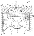
図1に示すように、筒内噴射型ガソリンエンジン(以下、エンジンという)10は、シリンダ11が形成されたシリンダブロック12と、シリンダブロック12の上面に締結されたシリンダヘッド13とを備えている。シリンダ11は、一端がシリンダブロック12の上面に開口するとともに、他端がシリンダブロック12に形成されたクランク室(図示しない)に開口しており、ピストン14を摺動可能に収容している。ピストン14は、ピストンピン15およびコネクティングロッド16を介してクランク室内に支持されたクランクシャフト(図示しない)に連結されている。図1は、ピストン14がシリンダ11内において上死点に位置する状態を示している。
<First Embodiment>
As shown in FIG. 1, a cylinder injection gasoline engine (hereinafter referred to as an engine) 10 includes a
ピストン14は、円形平坦状のピストン頭頂部18と、ピストン頭頂部18の周縁部からクランク室側へと垂設されたピストンスカート部19と備え、下方(クランク室側)に向けて開口した有底の筒形を呈する。ピストン14のシリンダヘッド13側を向く外面をピストンの頂面20といい、シリンダ11の内壁に対向する外面を周面21という。ピストンスカート部19の互いに対向する部分には、ピストンピン15が挿入されるピン孔22が形成されている。ピストン14の周面21には、周方向に延在する環状溝である第1溝23、第2溝24、オイルリング溝25がシリンダヘッド13側より順に凹設されている。第1溝23には第1コンプレッションリング26が、第2溝24には第2コンプレッションリング27が、オイルリング溝25にはオイルリング28がそれぞれ嵌着されている。オイルリング溝25の底部には、ピストンスカート部19の内面に連通するオイル孔29が形成されている。
The
図1および図2に示すように、ピストン14の頂面20は、頂面中央部32と、頂面中央部32を囲む環状の頂面周縁部33とに区画されている。頂面中央部32は、ピストン14の軸線Aを中心とした円形状の直交面に形成されている。頂面周縁部33は、軸線Aを中心とした径方向外方に進むほどクランク室側へと進むように傾斜したテーパ面となっている。換言すると、ピストン14の頂面20は、頂面中央部32がシリンダヘッド13側に突出した円錐台形状となっている。
As shown in FIGS. 1 and 2, the
シリンダヘッド13のシリンダ11に対応する部分には、シリンダ11に連続するようにカップ状の凹部35が凹設されている。凹部35は、上死点近傍に位置するピストン14の頂面20との間に燃焼室36を画成する。凹部35は、頂面中央部32に対向する凹部中央部37と、頂面周縁部33に対向する凹部周縁部38とに区画されている。凹部周縁部38は、頂面周縁部33のテーパ面と対向可能なように(断面において平行となるように(図1参照))、ピストン14の軸線Aと概ね一致するシリンダ11の軸線Bに対して傾斜した面から構成されている。凹部中央部37は、凹部周縁部38から稜線を介してさらに深くなるように、凹部周縁部38よりも急勾配となる壁部を含んでいる。
A cup-
ピストン14が上死点に位置するときには、頂面中央部32と対向する凹部中央部37との間には、燃焼室主部41が画成される。このとき、頂面周縁部33は凹部周縁部38と所定の微小な間隔をおいて対向し、それらの間に円環状のスキッシュ部42が画成される。燃焼室主部41およびスキッシュ部42を合わせて燃焼室36という。スキッシュ部42は、燃焼室主部41を囲むように配置され、その体積は燃焼室主部41の体積に比べて十分に小さく形成されている。
When the
凹部中央部37の中央部には、インジェクタ44が挿入されるインジェクタ孔45と、スパークプラグ46が挿入されるプラグ孔47とが形成されている。また、図3に特にしめすように、凹部中央部37の左半部には2つの吸気通路48が開口し、右半部には2つの排気通路49が開口している。なお、図示しないが、吸気通路48および排気通路49には、吸気バルブおよび排気バルブがそれぞれ開閉可能に設けられている。
An
図1および図3に示すように、ピストン14の頂面20の吸気通路48に対応する左半部には、5つの冷却通路50が形成されている。各冷却通路50は、同様の形態を有し、図3に示すように、ピストン14の径方向に延在し、軸線Aを中心とした回転対称位置にそれぞれ所定の間隔をおいて配置されている。
As shown in FIGS. 1 and 3, five
図1および図2に示すように、冷却通路50は、頂面中央部32の周縁部(頂面周縁部33との境界近傍部分)に開口する第1端部51から軸線Aと平行に延びる第1通路(第1部分)52と、頂面周縁部33と周面21との境界部に開口する第2端部53から軸線Aと直交する方向(ピストン14の径方向)に延び、第1通路52に連通する第2通路(第2部分)54と備えている。
As shown in FIG. 1 and FIG. 2, the
以上のように構成したエンジン10の作用効果について説明する。燃焼室主部41に開口する第1端部51近傍の位置C(図2参照)でのガス速度をV1(m/s)、ガス圧力をP1(Pa)、ガス密度をρ1(kg/m3)、高さをz1(m)とし、スキッシュ部42に開口する第2端部53近傍の位置D(図2参照)でのガス速度をV2(m/s)、ガス圧力をP2(Pa)、ガス密度をρ2(kg/m3)、高さをz2(m)とすると、ベルヌーイの定理より、以下の数1に示す関係が成り立つ。gは、重力加速度(9.8m/s2)である。

燃焼室36はスキッシュ部42を有するため、圧縮行程においてピストン14が上死点近傍で変位することによって、ガスがスキッシュ部42から燃焼室主部41へと流れるスキッシュ流が発生し、位置Dでのガス速度V2は位置Cでのガス速度V1よりも大きくなる。また、膨張行程においてピストン14が上死点近傍で変位することによって、ガスが燃焼室主部41からスキッシュ部42へと流れる逆スキッシュ流が発生し、位置Dでのガス速度V2は位置Cでのガス速度V1よりも大きくなる。スキッシュ流または逆スキッシュ流が発生し、位置Dでのガス速度V2が位置Cでのガス速度V1よりも大きい場合には、各位置でのガス速度の向きに関わらず、上記の数2より、位置Cでのガス圧力P1は位置Dでのガス圧力P2よりも大きくなる。これにより、冷却通路50の第1端部51と第2端部53との間で圧力差が生じ、冷却通路50内を第1端部51から第2端部53へとガスが流通する。冷却通路50内をガスが流通することによって、冷却通路50の内壁とガスとの間で熱交換が行われ、ピストン14の頂面周縁部33が冷却される。また、冷却通路50内はガスで満たされるため、ピストン頭頂部18内に断熱部(断熱層)を形成したのと同等の効果を得ることができる。また、冷却通路50の第2端部53から噴出されるガスが頂面周縁部33の表面を覆い、断熱層を形成することによって、頂面周縁部33の温度上昇が抑制される。
Since the
本実施形態のエンジン10は、冷却通路50の第1端部51を燃焼室主部41に連通させ、第2端部53をスキッシュ部42に連通させたことによって、スキッシュ流または逆スキッシュ流に起因する圧力差を利用して、冷却通路50内にガスを流通させることができる。また、第2端部53を頂面20と周面21との境界部に配置したことによって、ノッキングが発生しやすい頂面20の縁部を冷却することができる。また、冷却通路50の経路長を長くすることができ、冷却量を増大させることができる。
The
頂面周縁部33をテーパ面とし、頂面中央部32をシリンダヘッド13側に突出させたことによって、軸線Aと平行な直線状の第1通路52と、軸線Aと直交する方向に延びる直線状の第2通路54とによって冷却通路50を構成することができる。第1通路52および第2通路54は、ドリル等による穿孔で容易に形成することができ、加工の容易化が図れる。また、第2通路54を軸線Aと直交する方向に延在させても、第2通路54と頂面20との間に十分な肉厚を確保することができ、ピストン14の剛性を確保することができ、熱応力に抗することができる。
The top surface
また、図3に示すように、燃焼室36の中でノッキングが発生しやすい吸気通路48に対応する左半部のみに冷却通路50を設けることによって、ピストン14の剛性低下を最小限に抑えつつ、ノッキング抑制効果を高めることができる。ノッキングは、吸気工程におけるタンブル流(縦渦)に起因して、燃焼室36の中で吸気通路48側に対応する部分で発生しやすいことが知られている。タンブル流は、吸気通路48から、凹部中央部37に沿ってスパークプラグ46、排気通路49側へと流れた後、ピストン14の頂面20の排気通路49側に対応する部分、頂面20の中央部、頂面20の吸気通路48に対応する部分へと順に流れる。スパークプラグ46によって発生した火炎は、タンブル流に乗って伝播するため、吸気通路48に対応する左半部に存在するガスはエンドガスとなる。そのため、吸気通路48に対応する左半部でノッキングが発生しやすくなっている。
Further, as shown in FIG. 3, the
次に、第1実施形態に係るエンジン10を一部変更した第2〜第4実施形態に係るエンジン100,200,300について説明する。各エンジン100,200,300では、ピストン14の頂面20の形状およびシリンダヘッド13の凹部35の形状が異なるが、いずれも燃焼室主部およびスキッシュ部を画成し、冷却通路は燃焼室主部とスキッシュ部とに連通している。そして、スキッシュ流および逆スキッシュ流に起因する圧力差を利用して冷却通路にガスを流通させる。以下の説明では、第1実施形態と同様の構成については、同じ符号を付し、説明を省略する。
Next,
<第2実施形態>
図4に示すように、第2実施形態に係るエンジン100では、ピストン14の頂面20が軸線Aに対して直交する平面状に形成されている。シリンダヘッド13の凹部35は、頂面20の中央部101(頂面中央部32に対応)に対向する部分のみに形成されている。図4に示すように、ピストン14が上死点に位置する状態で、頂面20の中央部101は凹部35との間に燃焼室主部102を画成し、頂面20の周縁部103はシリンダヘッド13の下面104との間にスキッシュ部105を画成する。冷却通路110は、頂面20の中央部101に開口する第1端部111から頂面20に対して傾斜してピストン14の径方向外方へと延びる第1通路112と、頂面20の周縁部103に開口する第2端部113から頂面20に対して傾斜してピストン14の径方向内方へと延びるとともに第1通路112に連通した第2通路114とから構成されている。このように、冷却通路110は、平面状の頂面20にも形成することができる。なお、図示しないが、冷却通路110は、第1実施形態と同様に、頂面20に複数形成されてもよい。また、第2端部113は、図示例よりも頂面20と周面21との境界部側に寄せて配置してもよい。
<Second Embodiment>
As shown in FIG. 4, in the
<第3実施形態>
図5に示すように、第3実施形態に係るエンジン200では、ピストン14の頂面20は、その中央部201が曲面状に凹設され(キャビティが形成され)、その周縁部202が平面状に形成されている。シリンダヘッド13の凹部35は、頂面20の中央部201に対向する部分のみに形成されている。図5に示すように、ピストン14が上死点に位置する状態で、頂面20の中央部201は凹部35との間に燃焼室主部204を画成し、頂面20の周縁部202はシリンダヘッド13の下面205との間にスキッシュ部206を画成する。冷却通路210は、中央部201の凹部の凹面207に開口する第1端部211からピストン14の径方向に延びる第1通路212と、頂面20の周縁部202に開口する第2端部213からピストン14の軸線Aと平行に延びるとともに第1通路212に連通した第2通路214とから構成されている。なお、図示しないが、冷却通路210は、第1実施形態と同様に、頂面20に複数形成されてもよい。
<Third Embodiment>
As shown in FIG. 5, in the
<第4実施形態>
図6に示すように、第4実施形態に係るエンジン300では、ピストン14の頂面20は、その中央部301が曲面状に凹設され(キャビティが形成され)、その周縁部302が平面状に形成されている。中央部301と周縁部302との境界部には、断面が台形状の突条304が環状に延設されている。突条304は、突出端側が先細となっており、上底(突出端側の面)305が、周縁部302のなす面と略平行となっている。
<Fourth embodiment>
As shown in FIG. 6, in the
シリンダヘッド13の凹部35は、頂面20の中央部301および突条304の中央部301側の斜面部306、突条304の上底305に対応する凹部中央部307と、突条304の周縁部302側の斜面部308に対応する凹部周縁部309とを有している。ピストン14が上死点に位置するときに、頂面20の中央部301および突条304の斜面部306、上底305は、凹部中央部307との間に燃焼室主部310を画成し、頂面20の周縁部302および突条304の斜面部308は、シリンダヘッド13の下面311および凹部周縁部309との間にスキッシュ部312を画成する。
The
冷却通路315は、突条304の上底305に開口する第1端部316からピストン14の軸線Aと平行に延びる第1通路317と、突条304の斜面部308に開口する第2端部318からピストン14の径方向に伸びるとともに第1通路317に連通した第2通路319とから構成されている。なお、図示しないが、冷却通路315は、第1実施形態と同様に、頂面20に複数形成されてもよい。
The
以上で具体的実施形態の説明を終えるが、本発明は上記実施形態に限定されることなく幅広く変形実施することができる。例えば、冷却通路50は、頂面20の吸気通路48に対応する部分に限らず、頂面20の全周に形成されてもよい。或いは、冷却通路50を吸気通路48に対応する部分により限定して、例えば、図3において、左端から時計回りおよび反時計回りにそれぞれ45°の範囲(合計90°)の頂面20に冷却通路50を設けてもよい。なお、冷却通路50の数および密度は適宜変更してよい。上述した各実施形態では、冷却通路は、平面視において、ピストンの径方向に延設されているが、径方向に対して傾斜させてもよい。また、冷却通路は、曲線状に形成してもよい。上記の第1〜第4実施形態では、燃焼室を画成するピストンおよびシリンダヘッドの代表的な形状を例示したが、これらに限られず、本発明は、燃焼室主部およびスキッシュ部を画成する様々な形状のピストンおよびシリンダヘッドを有するエンジンに適用することができる。また、実施形態では、ガソリンエンジンに適用した例を示したが、本発明はディーゼルエンジンにも同様に適用することができる。
Although the description of the specific embodiment is finished as described above, the present invention is not limited to the above embodiment and can be widely modified. For example, the
10…筒内噴射型ガソリンエンジン(内燃機関)、13…シリンダヘッド、14…ピストン、20…頂面、21…周面、32…頂面中央部、33…頂面周縁部、35…凹部、36…燃焼室、37…凹部中央部、38…凹部周縁部、41…燃焼室主部、42…スキッシュ部、48…吸気通路、49…排気通路、50…冷却通路、51…第1端部、52…第1通路(第1部分)、53…第2端部、54…第2通路(第2部分)
DESCRIPTION OF
Claims (4)
前記ピストンは、第1端部が前記頂面の前記燃焼室主部に対向する部分に開口するとともに、第2端部が前記頂面の前記スキッシュ部に対向する部分に開口する冷却通路を有することを特徴とする内燃機関。 An internal combustion engine in which a combustion chamber defined between a piston and a cylinder head has a squish portion corresponding to a peripheral portion of a top surface of the piston and a combustion chamber main portion corresponding to a central portion of the top surface. There,
The piston has a cooling passage having a first end opening in a portion of the top surface facing the combustion chamber main portion and a second end opening in a portion of the top surface facing the squish portion. An internal combustion engine characterized by that.
前記冷却通路は、前記第1端部が、前記ピストンの軸線方向において、前記第2端部よりも前記シリンダヘッド側に配置され、前記第1端部から前記ピストンの軸線方向と平行に延在する第1部分と、前記第2端部から前記ピストンの軸線方向と垂直に延在する第2部分とを有することを特徴とする、請求項1または請求項2に記載の内燃機関。 The peripheral portion of the top surface of the piston is formed in a tapered surface in which the radially inner side of the piston is raised,
In the cooling passage, the first end portion is disposed closer to the cylinder head than the second end portion in the axial direction of the piston, and extends in parallel with the axial direction of the piston from the first end portion. 3. The internal combustion engine according to claim 1, further comprising: a first portion that extends from the second end portion and a second portion that extends perpendicular to an axial direction of the piston.
前記冷却通路は、前記ピストンの頂部の前記吸気通路に対応する側に設けられていることを特徴とする、請求項1〜請求項3のいずれかの項に記載の内燃機関。 The cylinder head has an intake passage and an exhaust passage in a portion corresponding to the main portion of the combustion chamber,
The internal combustion engine according to any one of claims 1 to 3, wherein the cooling passage is provided on a side of the top portion of the piston corresponding to the intake passage.
Priority Applications (1)
| Application Number | Priority Date | Filing Date | Title |
|---|---|---|---|
| JP2010153517A JP2012017654A (en) | 2010-07-06 | 2010-07-06 | Internal combustion engine |
Applications Claiming Priority (1)
| Application Number | Priority Date | Filing Date | Title |
|---|---|---|---|
| JP2010153517A JP2012017654A (en) | 2010-07-06 | 2010-07-06 | Internal combustion engine |
Publications (1)
| Publication Number | Publication Date |
|---|---|
| JP2012017654A true JP2012017654A (en) | 2012-01-26 |
Family
ID=45603090
Family Applications (1)
| Application Number | Title | Priority Date | Filing Date |
|---|---|---|---|
| JP2010153517A Pending JP2012017654A (en) | 2010-07-06 | 2010-07-06 | Internal combustion engine |
Country Status (1)
| Country | Link |
|---|---|
| JP (1) | JP2012017654A (en) |
Cited By (2)
| Publication number | Priority date | Publication date | Assignee | Title |
|---|---|---|---|---|
| WO2015162796A1 (en) * | 2014-04-25 | 2015-10-29 | 日産自動車株式会社 | Cylinder direct injection internal combustion engine |
| JP2016089651A (en) * | 2014-10-30 | 2016-05-23 | 本田技研工業株式会社 | Internal combustion engine |
-
2010
- 2010-07-06 JP JP2010153517A patent/JP2012017654A/en active Pending
Cited By (2)
| Publication number | Priority date | Publication date | Assignee | Title |
|---|---|---|---|---|
| WO2015162796A1 (en) * | 2014-04-25 | 2015-10-29 | 日産自動車株式会社 | Cylinder direct injection internal combustion engine |
| JP2016089651A (en) * | 2014-10-30 | 2016-05-23 | 本田技研工業株式会社 | Internal combustion engine |
Similar Documents
| Publication | Publication Date | Title |
|---|---|---|
| US6314933B1 (en) | Piston for internal combustion engines | |
| CN102959222B (en) | For the piston of spark ignition engine | |
| US9482145B2 (en) | Toroidal combustion chamber with side injection | |
| JP6299737B2 (en) | Multi-cylinder engine cooling structure | |
| CN104271916B (en) | The piston of explosive motor | |
| JP2014084790A (en) | Piston of cylinder direct injection type internal combustion engine | |
| US20150198114A1 (en) | Piston for an internal combustion engine | |
| EP3030768B1 (en) | A swirl-conserving combustion chamber construction for opposed-piston engines | |
| CN107636276B (en) | Four-stroke internal combustion engine and piston for the same | |
| CN103764983B (en) | Engine unit for enhanced cooling | |
| WO2021006119A1 (en) | Piston for internal combustion engine, and internal combustion engine | |
| JP6006276B2 (en) | Internal combustion engine | |
| JP2009293611A (en) | Engine piston | |
| JP2012017654A (en) | Internal combustion engine | |
| US7216612B2 (en) | Internal combustion engine having cylinder formed with water jacket and vehicle provided with the same | |
| JP4256790B2 (en) | Gas engine piston | |
| CA3182721A1 (en) | Flow guiding device, cylinder head assembly, and internal combustion engine | |
| JP5565438B2 (en) | Piston for internal combustion engine | |
| JP2018053829A (en) | Piston for internal combustion engine | |
| JP7310175B2 (en) | engine | |
| KR200406092Y1 (en) | Liner structure with improved cylinder cooling | |
| JP6344456B2 (en) | Engine combustion chamber structure | |
| CN121382456A (en) | Cylinder cover and engine | |
| JP2007187107A (en) | Internal combustion engine | |
| JP2014020285A (en) | Engine piston |