JP2012021981A - Method and device for performing time measurement in complex manner - Google Patents
Method and device for performing time measurement in complex manner Download PDFInfo
- Publication number
- JP2012021981A JP2012021981A JP2011144248A JP2011144248A JP2012021981A JP 2012021981 A JP2012021981 A JP 2012021981A JP 2011144248 A JP2011144248 A JP 2011144248A JP 2011144248 A JP2011144248 A JP 2011144248A JP 2012021981 A JP2012021981 A JP 2012021981A
- Authority
- JP
- Japan
- Prior art keywords
- time stamp
- information
- event
- global time
- global
- Prior art date
- Legal status (The legal status is an assumption and is not a legal conclusion. Google has not performed a legal analysis and makes no representation as to the accuracy of the status listed.)
- Granted
Links
Images


Classifications
-
- G—PHYSICS
- G01—MEASURING; TESTING
- G01R—MEASURING ELECTRIC VARIABLES; MEASURING MAGNETIC VARIABLES
- G01R31/00—Arrangements for testing electric properties; Arrangements for locating electric faults; Arrangements for electrical testing characterised by what is being tested not provided for elsewhere
- G01R31/28—Testing of electronic circuits, e.g. by signal tracer
- G01R31/317—Testing of digital circuits
- G01R31/3181—Functional testing
- G01R31/319—Tester hardware, i.e. output processing circuits
- G01R31/31903—Tester hardware, i.e. output processing circuits tester configuration
- G01R31/31907—Modular tester, e.g. controlling and coordinating instruments in a bus based architecture
Landscapes
- Engineering & Computer Science (AREA)
- General Engineering & Computer Science (AREA)
- Physics & Mathematics (AREA)
- General Physics & Mathematics (AREA)
- Tests Of Electronic Circuits (AREA)
- Debugging And Monitoring (AREA)
Abstract
【課題】被試験デバイスの複数の異なる信号間での時間測定を効率よく行う試験装置を提供する。
【解決手段】自動試験装置は、複数のシステムモジュールを備える。各システムモジュールは、一の時間測定部を備える。時間測定部に備えられたグローバル・タイム・スタンプ・モジュールは、複数のグローバル・タイム・スタンプ・コアを備え、該コアはそれぞれ、少なくとも2つの情報を受信する情報受信部と、コア入力においてイベントを受信するイベント受信部と、コア入力で受信されるイベントから対象イベントを決定するイベント決定部と、対象イベントが決定されると、クロック情報に対応するタイム・スタンプ・カウンタの現在のステータスを記録するようにタイム・スタンプ・メモリに指示する指示部とを備える。グローバル・タイム・スタンプ・モジュールはさらに、複数のグローバル・タイム・スタンプ・コアに共通時間基準を供給する供給部を備える。
【選択図】図2A test apparatus for efficiently measuring time between a plurality of different signals of a device under test is provided.
An automatic test apparatus includes a plurality of system modules. Each system module includes one time measuring unit. The global time stamp module provided in the time measurement unit includes a plurality of global time stamp cores, each of which receives an event at the core input and an information reception unit that receives at least two pieces of information. The event receiving unit to receive, the event determining unit for determining the target event from the event received at the core input, and when the target event is determined, record the current status of the time stamp counter corresponding to the clock information And an instruction unit for instructing the time stamp memory. The global time stamp module further comprises a supply that supplies a common time reference to a plurality of global time stamp cores.
[Selection] Figure 2
Description
本発明は、集積回路の試験を行なう自動試験装置(ATE)に関する。 The present invention relates to an automatic test equipment (ATE) for testing integrated circuits.
[関連出願]
本願は、米国仮特許出願第61/363,515号(出願日:2010年7月12日)および米国特許出願第13/013,495号の出願日の恩恵を主張する。両出願の内容は参照により本願に組み込まれる。
[Related applications]
This application claims the benefit of the filing dates of US Provisional Patent Application No. 61 / 363,515 (filing date: July 12, 2010) and US Patent Application No. 13 / 013,495. The contents of both applications are incorporated herein by reference.
ATEでは、1つの被試験デバイス(DUT)の複数の異なるピンの信号間のタイミング関係を複合的に測定する必要性が益々高まっている。混合信号(mixed signal)デバイスを試験する際には特にそうである。信号間で多くの時間測定を行なう必要があるが、このような時間測定は、非確定的であり、複数の異なるATE機器が生成する刺激との関係性が弱い。このような時間測定によって、試験スループットが大きく制限される一方、試験コストが大幅に増加してしまう。 In ATE, there is an increasing need to complexly measure timing relationships between signals on different pins of a device under test (DUT). This is especially true when testing mixed signal devices. Many time measurements need to be made between signals, but such time measurements are non-deterministic and weakly related to stimuli generated by different ATE devices. Such time measurement greatly limits the test throughput, but significantly increases the test cost.
このため、本発明の1以上の実施形態は、上述した問題のうち少なくとも1つを解決するATEおよびATEで利用される方法を提供することを目的とする。 Thus, one or more embodiments of the present invention aim to provide an ATE and a method used in the ATE that solve at least one of the problems described above.
この目的は、独立請求項に記載した装置および方法によって達成することができる。従属請求項には好ましい実施形態を記載する。 This object can be achieved by the apparatus and method described in the independent claims. The dependent claims describe preferred embodiments.
具体的には、複数のシステムモジュールを備える自動試験装置で用いられる装置によって上記の目的は達成される。一のシステムモジュールは、一の時間測定部(TMU)を備え、時間測定部(TMU)は、グローバル・タイム・スタンプ・モジュールを備え、グローバル・タイム・スタンプ・モジュールは、複数のグローバル・タイム・スタンプ・コアを備える。 Specifically, the above object is achieved by an apparatus used in an automatic test apparatus having a plurality of system modules. One system module includes one time measurement unit (TMU), the time measurement unit (TMU) includes a global time stamp module, and the global time stamp module includes a plurality of global time stamp modules. Has a stamp core.
複数のグローバル・タイム・スタンプ・コアはそれぞれ、少なくとも2つの情報を受信する情報受信部を備え、受信する2つの情報のうち第1の情報はクロック情報を含み、受信する2つの情報のうち第2の情報は同期情報を含む。グローバル・タイム・スタンプ・コアはさらに、複数のグローバル・タイム・スタンプ・コアによるデータ取得を同期させるべく、コア入力においてイベントを受信するイベント受信部を備える。グローバル・タイム・スタンプ・コアはさらに、コア入力で受信される前記イベントから対象イベントを決定するイベント決定部と、対象イベントが決定されると、クロック情報に対応するタイム・スタンプ・カウンタの現在のステータスを記録するようにタイム・スタンプ・メモリに指示する指示部とを備える。 Each of the plurality of global time stamp cores includes an information receiving unit that receives at least two pieces of information. The first information among the two pieces of received information includes clock information. The information 2 includes synchronization information. The global time stamp core further comprises an event receiver for receiving events at the core input to synchronize data acquisition by the plurality of global time stamp cores. The global time stamp core further includes an event determination unit that determines a target event from the event received at the core input, and a current time stamp counter corresponding to the clock information when the target event is determined. And an instruction unit for instructing the time stamp memory to record the status.
グローバル・タイム・スタンプ・モジュールはさらに、複数のグローバル・タイム・スタンプ・コアに共通時間基準を供給することによって、複数のグローバル・タイム・スタンプ・コアによるデータ取得を同期させる供給部を備える。 The global time stamp module further comprises a supply that synchronizes data acquisition by the plurality of global time stamp cores by supplying a common time reference to the plurality of global time stamp cores.
電子機器、特に、同期デジタル回路において、クロック情報とは、ロー状態とハイ状態との間で変動するタイプの信号であり、複数の回路の動作を調整するために用いられるとしてよい。クロック情報は、例えば、クロック生成器によって生成される。より複雑な構成も利用され得るが、最も一般的なクロック信号は、ディーティサイクルが50%の方形波の形状を取り、周波数は一定であることが多い。同期を取るためにクロック情報および/またはクロック信号を用いる回路は、クロックサイクルの立ち上がりエッジまたは立ち下がりエッジのいずれかでアクティブとなり、ダブルデータレートの場合には、クロックサイクルの立ち上がりエッジおよび立ち下がりエッジの両方でアクティブとなるとしてよい。 In electronic devices, particularly synchronous digital circuits, clock information is a type of signal that fluctuates between a low state and a high state, and may be used to adjust the operation of a plurality of circuits. The clock information is generated by, for example, a clock generator. More complex configurations may be used, but the most common clock signal often takes the form of a square wave with a duty cycle of 50% and the frequency is often constant. Circuits that use clock information and / or clock signals to synchronize are active on either the rising or falling edge of the clock cycle, and for double data rates, the rising and falling edges of the clock cycle Both may be active.
同期情報は多岐にわたり、同期が開始された時間、同期にかかった時間、同期させる対象、同期対象のステータス、データを処理する時間等が含まれるとしてよい。本発明はこのため、分散している時間測定素子を、好ましくは複数のグローバル・タイム・スタンプ・コアのデータ取得の時間が同期するように、同期させるという目的を達成する。 The synchronization information is diverse, and may include the time when the synchronization is started, the time taken for the synchronization, the object to be synchronized, the status of the object to be synchronized, the time for processing the data, and the like. The present invention thus achieves the object of synchronizing the distributed time measuring elements, preferably so that the time of data acquisition of the plurality of global time stamp cores is synchronized.
ATEで同期を実現する方法には複数ある。簡単な方法としては、例えば「スタートリガ」を用いて、トリガソースからトリガデスティネーションまたはトリガデスティネーション群までの高帯域幅信号経路を走らせる方法がある。このトリガメカニズムでは、アナログのマルチプレクサおよびセレクタを利用すると共に、さまざまなデスティネーションのための多数の個別のケーブル、または、何らかの種類の「トリガバス」を用いる。別の方法では、ベクトル同期(装置イネーブル(Enable Instrument:EINST))を利用し、1つのシーケンサを利用し、テスタにおいてEINSTトークンを含むシーケンス制御ベクトルを分配する。 There are a plurality of methods for realizing synchronization in ATE. A simple method is to run a high bandwidth signal path from a trigger source to a trigger destination or group of trigger destinations using, for example, a “star trigger”. This trigger mechanism utilizes analog multiplexers and selectors, as well as a number of individual cables for various destinations, or some kind of “trigger bus”. Another method uses vector synchronization (Enable Instrument: EINST), uses one sequencer, and distributes sequence control vectors including EINST tokens in the tester.
デジタル時間基準を設けることによって、システムクロックとベクトル時間との間の関係について、正確なものとすることができると共にデジタル制御が可能となる。このプロセスは、以下のようにまとめることができる。試験において、最初のベクトルがクロックサイクル境界で開始され、後続のベクトルはそれぞれ、先行する全てのベクトル時間の合計に等しい時間だけ間隔を空けて開始され、後続の各ベクトルの開始時間は、特定のクロックサイクルおよびこのサイクルの一部によって定められる。 By providing a digital time reference, the relationship between the system clock and vector time can be accurate and digitally controlled. This process can be summarized as follows. In the test, the first vector is started at a clock cycle boundary, each subsequent vector is started at an interval equal to the sum of all preceding vector times, and the starting time of each subsequent vector is a specific Defined by clock cycle and part of this cycle.
コア入力イベントは、試験中にDUTが発生させるイベントであればどのようなイベントであってもよい。対象イベントは、発生したコア入力イベントのうち特に有用なイベントであることが好ましく、ATEまたはATEの一部によって判断される。 The core input event may be any event that is generated by the DUT during the test. The target event is preferably a particularly useful event among the generated core input events, and is determined by the ATE or a part of the ATE.
共通時間基準とは、上述のクロック情報、クロック情報の一部、上述の同期情報、同期情報の一部、これらの情報またはこれらの情報の一部または複数のグローバル・タイム・スタンプ・コアのデータ取得を同期させる上で利用され得る任意のその他の有用な情報の任意の組み合わせであってよい。 The common time reference is the above clock information, a part of the clock information, the above synchronization information, a part of the synchronization information, these information or a part of these information or data of a plurality of global time stamp cores. It can be any combination of any other useful information that can be utilized in synchronizing the acquisition.
イベントのタイム・スタンプは、システム全体の任意の対象信号について並行して記録され、並行して記録されるとしてよい。そして、時間測定は、タイム・スタンプ記録間の時間差を計算することによって簡単に行なうとしてよい。 The time stamp of the event may be recorded in parallel for any target signal of the entire system and may be recorded in parallel. Time measurement may then be performed simply by calculating the time difference between time stamp records.
記録を並行して行なうため、多くの異なる時間スタンプ、例えば、時間値が並行して記録される可能性がある。1つのテストサイクルが完了すると、通常はデジタルパターンによって、全ての絶対測定結果が既に記録されている。そして、システムコントローラは、必要なタイム・スタンプを全て収集して、必要となる相対タイミングを計算するとしてよい。 Because the recording is done in parallel, many different time stamps, for example time values, can be recorded in parallel. When one test cycle is completed, all absolute measurement results are already recorded, usually in a digital pattern. The system controller may then collect all necessary time stamps and calculate the required relative timing.
上述の方法によると、DUTの試験に必要な試験時間を大幅に短縮することができるとしてよい。マルチサイトに用いられる場合であっても、シングルサイトで用いられる場合に比べてオーバーヘッドが非常に限られている。試験時間が増加する理由は、複数の異なるDUTのタイム・スタンプ値を読み出して、最後に計算を行なうことが原因である可能性がある。このため、本発明では、高い試験スループットを維持しつつ複合的な時間測定を実行するとしてよい。本発明に係る装置は、試験時間を改善することに加えて、搭載ボードの設計を簡略化し、搭載ボードのコストを低減し、信頼性を高めるとしてよい。 According to the above-described method, the test time required for testing the DUT may be significantly shortened. Even when it is used for multi-sites, the overhead is very limited compared to that for single-site use. The reason for the increase in test time may be due to reading the time stamp values of different DUTs and performing the calculation at the end. For this reason, in the present invention, multiple time measurements may be performed while maintaining a high test throughput. In addition to improving the test time, the apparatus according to the present invention may simplify the design of the mounting board, reduce the cost of the mounting board, and increase the reliability.
本発明の一実施形態によると、時間測定部の入力の数は少なくとも、被試験デバイスに対するシステムモジュールのI/Oポートの数と同じである。被試験デバイスに対するシステムモジュールのI/Oポートの数と同じであることが好ましい。 According to one embodiment of the present invention, the number of inputs of the time measurement unit is at least the same as the number of I / O ports of the system module for the device under test. Preferably, it is the same as the number of system module I / O ports for the device under test.
本発明の別の実施形態によると、当該装置は、複数の異なる時間測定部の複数の異なる分解能をスケーリングして一の統一分解能を提供するスケーリング部を備える。本発明の別の実施形態によると、当該装置は、タイム・スタンプ・カウンタの2つの値の間のイベント時間を補間する補間部を備える。 According to another embodiment of the invention, the apparatus comprises a scaling unit that scales a plurality of different resolutions of a plurality of different time measuring units to provide a unified resolution. According to another embodiment of the invention, the apparatus comprises an interpolator that interpolates the event time between two values of the time stamp counter.
本発明の別の好ましい実施形態によると、当該装置は、アナログ信号をデジタル化した値を比較するアナログ比較器をエミュレートするエミュレート部を備え、タイム・スタンプは、アナログ信号をデジタル化した値を比較するデジタル比較器によって生成される。 According to another preferred embodiment of the present invention, the apparatus comprises an emulating unit that emulates an analog comparator that compares the digitized value of the analog signal, and the time stamp is a digitized value of the analog signal. Generated by a digital comparator.
上述のシステムアーキテクチャは、グローバル・タイム・スタンプ・モジュールおよびグローバル・タイム・スタンプ・コアの全てについて同じハードウェアとすることに限定されない。タイム・スタンプ・カウンタは、信号群毎に分解能を変えるとしてよい。低速信号、例えば、電圧/電流(VI)源の信号比較器は、デジタルピンの比較器に比べて低い分解能で記録するとしてよい。モジュールファームウェアまたはドライバソフトウェアは、ハードウェア毎に異なる分解能を統一分解能にスケーリングするとしてよい。このようなスケーリング構成によって、例えば、低分解能信号および高分解能信号を異なるデバイスで処理することができるという利点が得られ、デバイスの複雑性をさらに低くすることができるので、試験コストがさらに低減されるとしてよい。 The system architecture described above is not limited to having the same hardware for all of the global time stamp module and the global time stamp core. The time stamp counter may change the resolution for each signal group. A low-speed signal, eg, a voltage / current (VI) source signal comparator, may record with a lower resolution than a digital pin comparator. Module firmware or driver software may scale different resolutions for each hardware to a unified resolution. Such a scaling configuration provides the advantage that, for example, low and high resolution signals can be processed by different devices, further reducing device complexity and thus further reducing test costs. It's okay.
高分解能での時間測定のために、グローバル・タイム・スタンプ・コアは、高分解能時間測定ハードウェアを追加で有するとしてよい。このハードウェアは、2つの連続するグローバル・タイム・スタンプ・カウンタの値の間のイベント時間を補間するとしてよい。高分解能時間測定ハードウェアの値は、グローバル・タイム・スタンプ・カウンタの値と共に格納されるとしてよい。 For time measurements at high resolution, the global time stamp core may have additional high resolution time measurement hardware. This hardware may interpolate the event time between two consecutive global time stamp counter values. The value of the high resolution time measurement hardware may be stored along with the value of the global time stamp counter.
タイム・スタンプの取得方法については、上述したアナログの比較器およびハードウェアを用いる以外の方法で取得する場合があるとしてよい。例えば、アナログの比較器が利用されていないデジタル制御VI源で取得するとしてよい。この場合、アナログ信号をデジタル化した値を比較してデジタルタイムスタンプを生成するデジタル比較器によって機能をエミュレートするとしてよい。 The time stamp may be acquired by a method other than using the analog comparator and hardware described above. For example, it may be obtained by a digital control VI source that does not use an analog comparator. In this case, the function may be emulated by a digital comparator that generates a digital time stamp by comparing values obtained by digitizing analog signals.
本発明の別の実施形態によると、当該装置は、複数の時間測定部について記録された現在のステータス(タイムスタンプ値)を収集する収集部を備える。本発明の別の実施形態によると、当該装置は、収集された前記タイム・スタンプ値(TS)に基づいて時間差を計算する計算部を備える。 According to another embodiment of the present invention, the apparatus includes a collection unit that collects a current status (time stamp value) recorded for a plurality of time measurement units. According to another embodiment of the present invention, the apparatus comprises a calculator for calculating a time difference based on the collected time stamp values (TS).
さらに、複数のグローバル・タイム・スタンプ・コアを備える自動試験装置で用いられる方法によって上記の本発明の目的は達成される。時間測定部を含んでいる各システムモジュールについて好ましい実施形態として、自動試験装置で用いられる当該方法は、少なくともグローバル・タイム・スタンプ・コアを備え、時間測定部を含んでいる各システムモジュールについてより好ましい実施形態として、自動試験装置で用いられる当該方法は、グローバル・タイム・スタンプ・コアを備える。 Furthermore, the above object of the present invention is achieved by a method used in an automatic test apparatus having a plurality of global time stamp cores. As a preferred embodiment for each system module including a time measurement unit, the method used in the automatic test apparatus is more preferable for each system module including at least a global time stamp core and including a time measurement unit. As an embodiment, the method used in the automatic test equipment comprises a global time stamp core.
複数のグローバル・タイム・スタンプ・コアはそれぞれ、少なくとも2つの情報を受信する段階を備える。受信する前記2つの情報のうち第1の情報はクロック情報を含み、前記受信する2つの情報のうち第2の情報は同期情報を含む。 Each of the plurality of global time stamp cores comprises receiving at least two pieces of information. Of the two information to be received, first information includes clock information, and of the two information to be received, second information includes synchronization information.
グローバル・タイム・スタンプ・コアはさらに、複数のグローバル・タイム・スタンプ・コアによるデータ取得を同期させるべく、コア入力においてイベントを受信する段階を備える。グローバル・タイム・スタンプ・コアはさらに、コア入力(CI)で受信される前記イベント(EV)から対象イベント(EV_INT)を決定する段階を備える。グローバル・タイム・スタンプ・コアはさらに、対象イベント(EV_INT)が決定されると、前記クロック情報(CL_INF)に対応するタイム・スタンプ・カウンタ(TSC)の現在のステータス(TS)を記録するようにタイム・スタンプ・メモリ(TSM)に指示する段階を備える。グローバル・タイム・スタンプ・モジュールのための方法はさらに、複数のグローバル・タイム・スタンプ・コア(GTSC)に共通時間基準を供給することによって、前記複数のグローバル・タイム・スタンプ・コア(GTSC)によるデータ取得を同期させる段階を備える。 The global time stamp core further comprises receiving an event at the core input to synchronize data acquisition by the plurality of global time stamp cores. The global time stamp core further comprises determining an event of interest (EV_INT) from the event (EV) received at the core input (CI). The global time stamp core further records the current status (TS) of the time stamp counter (TSC) corresponding to the clock information (CL_INF) when the target event (EV_INT) is determined. Instructing a time stamp memory (TSM). A method for a global time stamp module is further provided by the plurality of global time stamp cores (GTSC) by providing a common time reference to the plurality of global time stamp cores (GTSC). Synchronizing data acquisition.
さらに、自動試験装置で用いられるグローバル・タイム・スタンプ・コアのための方法を含む自動試験装置で用いられる方法によって上記の本発明の目的は達成される。当該方法は、少なくとも2つの情報を受信する段階を備え、受信する2つの情報のうち第1の情報はクロック情報を含み、受信する2つの情報のうち第2の情報は同期情報を含む。上述した自動試験装置で用いられるグローバル・タイム・スタンプ・コアのための方法はさらに、複数のグローバル・タイム・スタンプ・コアによるデータ取得を同期させるべく、コア入力においてイベントを受信する段階を備える。上述した自動試験装置で用いられるグローバル・タイム・スタンプ・コアのための方法はさらに、コア入力で受信されるイベントから対象イベントを決定する段階を備える。上述した自動試験装置で用いられるグローバル・タイム・スタンプ・コアのための方法はさらに、対象イベントが決定されると、前記クロック情報に対応するタイム・スタンプ・カウンタの現在のステータスを記録するようにタイム・スタンプ・メモリに指示する段階を備える。 Furthermore, the above objects of the present invention are achieved by a method used in an automatic test apparatus, including a method for a global time stamp core used in an automatic test apparatus. The method includes receiving at least two pieces of information, wherein the first information among the two pieces of received information includes clock information, and the second information among the two pieces of received information includes synchronization information. The method for a global time stamp core used in the automatic test equipment described above further comprises receiving an event at the core input to synchronize data acquisition by multiple global time stamp cores. The method for the global time stamp core used in the automatic test apparatus described above further comprises determining a target event from the event received at the core input. The method for the global time stamp core used in the automatic test apparatus described above further records the current status of the time stamp counter corresponding to the clock information when the target event is determined. Instructing the time stamp memory.
本発明の一実施形態によると、上述した自動試験装置で用いられるグローバル・タイム・スタンプ・コアのための方法において、タイム・スタンプ・カウンタは、同期情報のリセット情報に応じてリセットされる。 According to an embodiment of the present invention, in the method for the global time stamp core used in the automatic test apparatus described above, the time stamp counter is reset according to the reset information of the synchronization information.
従来の自動試験装置では、専用TMUの入力間、または、単一の入力において直接時間測定を実行している。測定毎に1つの値が読み出されるとしてよい。 Conventional automatic test equipment performs time measurements directly between dedicated TMU inputs or at a single input. One value may be read for each measurement.
本発明の実施形態に係る装置および/または方法の一部の実施形態について、添付図面を参照しつつ、例示を目的として、説明する。添付図面は以下の通りである。 Some embodiments of apparatus and / or methods according to embodiments of the present invention will now be described by way of example with reference to the accompanying drawings. The attached drawings are as follows.
本発明を好ましい実施形態を参照しつつ以下で説明するが、好ましい実施形態は、本発明の範囲を限定するものではなく本発明の一例を説明するためのものである。実施形態で説明する特徴および当該特徴の組み合わせ全てが必ずしも本発明を実施する上で必須なわけではない。 The present invention will be described below with reference to preferred embodiments, which are not intended to limit the scope of the invention, but to illustrate an example of the invention. All the features described in the embodiments and combinations of the features are not necessarily essential for carrying out the present invention.
本明細書では、「部材Aが部材Bに接続されている状態」という記載は、部材Aおよび部材Bが直接物理的に接続されている状態、および、部材Aおよび部材Bが両者間の電気接続に影響を与えないその他の部材を介して間接的に接続されている状態を意味する。同様に、「部材Cが部材Aと部材Bとの間に配設されている状態」という記載は、部材Aおよび部材C、または、部材Bおよび部材Cが互いに直接接続されている状態に加えて、これらの部材が電気接続に影響を与えないその他の部材を介して間接的に接続されている状態を意味する。 In this specification, the description “the state in which the member A is connected to the member B” refers to the state in which the member A and the member B are directly physically connected, and the electrical connection between the member A and the member B. It means a state of being indirectly connected through other members that do not affect the connection. Similarly, “the state in which the member C is disposed between the member A and the member B” is not limited to the state in which the member A and the member C or the member B and the member C are directly connected to each other. This means that these members are indirectly connected via other members that do not affect the electrical connection.
以下に記載する実施形態は試験装置に関する。より具体的には、被試験デバイス(DUT)の試験を行なう自動試験装置(ATE)に関する。 The embodiments described below relate to a test apparatus. More specifically, the present invention relates to an automatic test apparatus (ATE) for testing a device under test (DUT).
図1は、ATEにおける従来の時間測定方法を説明する概略図である。同図に示すようなATEにおいて時間測定を行なうための従来の設定では、複数の異なるシステムモジュール(SYSMOD)、例えば、デジタルモジュール、任意波形生成器/デジタイザ、プログラム可能な電圧源および電流源(VI源)等が、搭載ボードを介してDUTにワイヤ接続されている。ATE内で利用可能な中央時間測定部(TMU)が別個に設けられている。TMUは、限られた数の時間測定用入力(IN)を有する。 FIG. 1 is a schematic diagram illustrating a conventional time measurement method in ATE. In a conventional setup for taking time measurements in an ATE as shown in the figure, a plurality of different system modules (SYSMOD), eg, digital modules, arbitrary waveform generator / digitizer, programmable voltage source and current source (VI Source) and the like are wire-connected to the DUT through the mounting board. There is a separate central time measurement unit (TMU) available within the ATE. The TMU has a limited number of time measurement inputs (IN).
時間測定を行なうべき任意のDUT信号は、特定用途向けリレーマトリクスを介して、TMUの入力(IN)にワイヤ接続される。このリレーマトリクスは、特定用途向けにATEのユーザによって構築されるとしてよい。この結果、先行技術に係るシステムでは、ハードウェアにかかる労力が大きく、搭載ボード(LB)の複雑性が大きくなる。TMUの入力(IN)の数が限られているので、時間測定はシリアルに行なう必要がある。このため、先行技術に係るシステムでは、試験プログラムの実行時間が長くなってしまう。 Any DUT signal to be timed is wired to the TMU input (IN) via an application specific relay matrix. This relay matrix may be constructed by ATE users for specific applications. As a result, in the system according to the prior art, the labor required for hardware is large, and the complexity of the mounting board (LB) increases. Since the number of inputs (IN) of the TMU is limited, the time measurement must be performed serially. For this reason, in the system which concerns on a prior art, the execution time of a test program will become long.
この問題を解決するべく、本発明では分散方式で時間測定を行なう。この新しいシステム方式については、図2に概略を示している。 In order to solve this problem, the present invention performs time measurement in a distributed manner. This new system scheme is outlined in FIG.
図2は、本発明に係る新しいシステム時間測定方法の概略を示す概略図である。本発明では、分散型時間測定システムのための方法および装置を説明する。本システムでは、ATEまたはその他の高精度測定機器において、特定用途の要件に応じた労力および分解能で、時間測定を複合的且つ並行して行う。 FIG. 2 is a schematic diagram showing an outline of a new system time measuring method according to the present invention. The present invention describes a method and apparatus for a distributed time measurement system. In this system, time measurement is performed in a complex and parallel manner in an ATE or other high-precision measurement equipment with effort and resolution according to the requirements of a specific application.
各システムモジュールは、DUTに対するモジュールI/Oの数と少なくとも同数の入力(IN)を持つTMUを有する。これはグローバルシステムの特徴であるので、この方式はグローバル・タイム・スタンプ方式と呼ばれる。図2は、グローバル・タイム・スタンプ方式のシステム方式の概略を示す図である。 Each system module has a TMU with at least as many inputs (IN) as the number of module I / Os to the DUT. Since this is a characteristic of the global system, this method is called a global time stamp method. FIG. 2 is a diagram showing an outline of the system method of the global time stamp method.
試験スループットを高く、且つ、試験コストを低く維持するためには、複数の時間測定を並行して実行することが必要となる。本発明では、上述の必要性に対処するべく、分散方式の時間測定機能を実現する方法の概略を説明する。本明細書で提案する方法は、高価な時間測定専用デバイスの利用を避けて、ハードウェアに係る労力を出来る限り小さく納めるべく、既製品を利用する。具体的には、本発明では、分解能が可変で、ATEチャネルの要件に応じてスケーリング可能な分散方式の時間測定システムを説明する。 In order to maintain a high test throughput and a low test cost, it is necessary to perform a plurality of time measurements in parallel. In the present invention, an outline of a method for realizing a distributed time measurement function will be described in order to cope with the above-described necessity. The method proposed in this specification uses off-the-shelf products in order to avoid the use of expensive time-measurement-dedicated devices and keep the hardware effort as small as possible. Specifically, the present invention describes a distributed time measurement system with variable resolution and scaleable according to ATE channel requirements.
本発明では、分散して設けられている時間測定部材を全て同期させることを含む、分散方式の時間測定方法を説明する。全機器の全ピンにおいて並行して時間を記録しつつ、イベント間の時間差を、イベント毎に記録された時間に基づいて減算を行なうことによって、計算するとしてよい。 In the present invention, a distributed time measuring method including synchronizing all time measuring members provided in a distributed manner will be described. The time difference between events may be calculated by subtracting based on the time recorded for each event while recording time in parallel on all pins of all devices.
図3は、一実施形態に係る新しいシステム時間測定方式を説明するべく、グローバル・タイム・スタンプ・モジュール(GTSM)を示す概略ブロック図である。 FIG. 3 is a schematic block diagram illustrating a global time stamp module (GTSM) to illustrate a new system time measurement scheme according to one embodiment.
自動試験装置で利用される装置は、複数のシステムモジュール(SYSMOD)を備える。各システムモジュール(SYSMOD)は、時間測定部(TMU)を備えており、時間測定部(TMU)は、グローバル・タイム・スタンプ・モジュール(GTSM)を備える。グローバル・タイム・スタンプ・モジュール(GTSM)は、複数のグローバル・タイム・スタンプ・コア(GTSC)を備える。 An apparatus used in the automatic test apparatus includes a plurality of system modules (SYSMOD). Each system module (SYSMOD) includes a time measurement unit (TMU), and the time measurement unit (TMU) includes a global time stamp module (GTSM). The global time stamp module (GTSM) comprises a plurality of global time stamp cores (GTSC).
グローバル・タイム・スタンプ・コア(GTSC)は、少なくとも2つの情報を受信する情報受信部を備える。受信する2つの情報のうち第1の情報は、クロック情報(CL_INF)を含み、受信する2つの情報のうち第2の情報は、同期情報(SYNC_INF)を含む。グローバル・タイム・スタンプ・コア(GTSC)はさらに、コア入力(IN)においてイベント(EV)を受信して、複数のグローバル・タイム・スタンプ・コア(GTSC)によるデータ取得を同期させるイベント受信部を備える。 The global time stamp core (GTSC) includes an information receiving unit that receives at least two pieces of information. The first information among the two pieces of information to be received includes clock information (CL_INF), and the second information among the two pieces of information to be received includes synchronization information (SYNC_INF). The global time stamp core (GTSC) further includes an event receiving unit that receives an event (EV) at a core input (IN) and synchronizes data acquisition by a plurality of global time stamp cores (GTSC). Prepare.
グローバル・タイム・スタンプ・コア(GTSC)はさらに、コア入力(IN)において受信したイベント(EV)の中から対象イベント(EV_INT)を決定するイベント決定部と、対象イベント(EV_INT)が決定されると、クロック情報(CL_INF)に対応するタイム・スタンプ・カウンタ(TSC)の現在のステータス(TS)を記録するようにタイム・スタンプ・メモリ(TSM)に指示する指示部とを備える。 The global time stamp core (GTSC) further determines an event determining unit for determining a target event (EV_INT) from events (EV) received at the core input (IN), and a target event (EV_INT) is determined. And an instruction unit for instructing the time stamp memory (TSM) to record the current status (TS) of the time stamp counter (TSC) corresponding to the clock information (CL_INF).
グローバル・タイム・スタンプ・モジュール(GTSM)はさらに、複数のグローバル・タイム・スタンプ・コアに共通時間基準を供給することによって、複数のグローバル・タイム・スタンプ・コア(GTSM)によるデータ取得を同期させる供給部を備える。 The Global Time Stamp Module (GTSM) further synchronizes data acquisition by multiple Global Time Stamp Cores (GTSM) by providing a common time reference to multiple Global Time Stamp Cores A supply unit is provided.
図3に示すように、当該装置では、時間測定部(TMU)の入力(IN)の数は少なくとも、被試験デバイスに対するシステムモジュール(SYSMOD)のI/Oポートの数と同じである。時間測定部(TMU)の入力(IN)の数は、被試験デバイスに対するシステムモジュール(SYSMOD)のI/Oポートの数と同じであることが好ましい。 As shown in FIG. 3, in this apparatus, the number of inputs (IN) of the time measurement unit (TMU) is at least the same as the number of I / O ports of the system module (SYSMOD) for the device under test. The number of inputs (IN) of the time measurement unit (TMU) is preferably the same as the number of I / O ports of the system module (SYSMOD) for the device under test.
当該装置はさらに、複数の異なる時間測定部(TMU)の複数の異なる分解能をスケーリングして統一分解能を提供するスケーリング部を備え、タイム・スタンプ・カウンタ(TSC)の2つの値の間のイベント時間を補間する補間部を備えるとしてよい。 The apparatus further includes a scaling unit that scales a plurality of different resolutions of a plurality of different time measurement units (TMUs) to provide a unified resolution, and an event time between two values of a time stamp counter (TSC). An interpolation unit may be provided for interpolating.
図3からさらに分かるように、当該装置は、アナログ信号をデジタル化した値を比較するアナログ比較器をエミュレートするエミュレート部を備え、タイム・スタンプTSは、アナログ信号をデジタル化した値を比較するデジタル比較器によって生成される。さらに、当該装置は、複数の時間測定部(TMU)の記録されたタイム・スタンプ値(TS)を収集する収集部と、収集されたタイム・スタンプ値(TS)に基づいて時間差を計算する計算部とを備える。 As can be further understood from FIG. 3, the apparatus includes an emulating unit that emulates an analog comparator that compares the digitized value of the analog signal, and the time stamp TS compares the digitized value of the analog signal. Generated by a digital comparator. Further, the apparatus includes a collecting unit that collects recorded time stamp values (TS) of a plurality of time measuring units (TMU), and a calculation that calculates a time difference based on the collected time stamp values (TS). A part.
さらに、本発明は、複数のグローバル・タイム・スタンプ・コア(GTSC)を備える、自動試験装置で用いられる方法を提供する。各システムモジュール(SYS_MOD)が時間測定部(TMU)を備え、自動試験装置で利用される当該方法は、少なくともグローバル・タイム・スタンプ・コア(GTSC)を備えていることが好ましい。また、各システムモジュール(SYS_MOD)が時間測定部(TMU)を備え、自動試験装置で利用される当該方法は、グローバル・タイム・スタンプ・コア(GTSC)を備えていることがより好ましい。 Furthermore, the present invention provides a method for use in automated test equipment comprising a plurality of global time stamp cores (GTSC). Each system module (SYS_MOD) includes a time measurement unit (TMU), and the method used in the automatic test apparatus preferably includes at least a global time stamp core (GTSC). Further, it is more preferable that each system module (SYS_MOD) includes a time measurement unit (TMU) and the method used in the automatic test apparatus includes a global time stamp core (GTSC).
グローバル・タイム・スタンプ・コア(GTSC)は、少なくとも2つの情報を受信する段階を備え、受信する2つの情報のうち第1の情報はクロック情報(CL_INF)を含み、受信する2つの情報のうち第2の情報は同期情報(SYNC_INF)を含む。 The global time stamp core (GTSC) includes a step of receiving at least two pieces of information, wherein the first information among the two pieces of received information includes clock information (CL_INF), The second information includes synchronization information (SYNC_INF).
グローバル・タイム・スタンプ・コア(GTSC)はさらに、複数のグローバル・タイム・スタンプ・コア(GTSC)によるデータ取得を同期させるべく、コア入力(CI)においてイベント(EV)を受信する段階を備える。 The global time stamp core (GTSC) further comprises receiving an event (EV) at the core input (CI) to synchronize data acquisition by the plurality of global time stamp cores (GTSC).
グローバル・タイム・スタンプ・コア(GTSC)はさらに、コア入力(IN)で受信されるイベント(EV)から対象イベント(EV_INT)を決定する段階を備える。グローバル・タイム・スタンプ・コア(GTSC)はさらに、対象イベント(EV_INT)が決定されると、クロック情報(CL_INF)に対応するタイム・スタンプ・カウンタ(TSC)の現在のステータス(TS)を記録するようにタイム・スタンプ・メモリ(TSM)に指示する段階を備える。 The global time stamp core (GTSC) further comprises determining a target event (EV_INT) from an event (EV) received at the core input (IN). The global time stamp core (GTSC) further records the current status (TS) of the time stamp counter (TSC) corresponding to the clock information (CL_INF) when the target event (EV_INT) is determined. Instructing a time stamp memory (TSM) as follows.
グローバル・タイム・スタンプ・モジュール(GTSM)のための方法はさらに、複数のグローバル・タイム・スタンプ・コア(GTSC)に共通時間基準を供給することによって、複数のグローバル・タイム・スタンプ・コア(GTSC)によるデータ取得を同期させる段階を備える。 The method for the global time stamp module (GTSM) further provides a plurality of global time stamp cores (GTSC) by providing a common time reference to the plurality of global time stamp cores (GTSC). ) To synchronize the data acquisition.
図4は、グローバル・タイム・スタンプ・システムの概略を示す概略図である。グローバル・タイム・スタンプ・モジュールは、当該モジュールの任意の1つのDUT入出力ピンに対して1つの入力を備えるとしてよい。グローバル・タイム・スタンプ・モジュールに対する入力は、任意の種類の信号であってよく、デジタル信号であることが好ましく、当該モジュール内で比較器によって生成されたデジタル信号であることが最も好ましい。 FIG. 4 is a schematic diagram showing an outline of the global time stamp system. The global time stamp module may have one input for any one DUT input / output pin of the module. The input to the global time stamp module may be any type of signal, preferably a digital signal, and most preferably a digital signal generated by a comparator within the module.
図4において、2つの共通信号から成る信号群を用いて、全てのグローバル・タイム・スタンプ・モジュールを同期させる。本発明は本例に限定されない。グローバル・タイム・スタンプ・モジュールを同期させる方法は他にも可能である。例えば、グローバル・タイム・スタンプ・モジュールを同期させるためには、3つ以上の共通信号を利用するとしてもよいし、信号を1つのみ利用するとしてもよい。また、グローバル・タイム・スタンプ・モジュールの同期に利用される2つ以上の信号は、同一の信号である必要はない。 In FIG. 4, a signal group consisting of two common signals is used to synchronize all global time stamp modules. The present invention is not limited to this example. There are other ways to synchronize the global time stamp module. For example, in order to synchronize the global time stamp module, three or more common signals may be used, or only one signal may be used. Further, two or more signals used for synchronization of the global time stamp module do not need to be the same signal.
これらの信号は、図4において示す、任意のグローバル・タイム・スタンプ・モジュールにおいて時間基準として用いられる自励クロック信号であるGTS_CLOCK信号、および、システム内の任意のGTSモジュール内の任意のチャネルについて共通の「ゼロ時間」ポイントを設定するために用いられるGTS_SYNC信号である。 These signals are common to the GTS_CLOCK signal, which is a self-excited clock signal used as a time reference in any global time stamp module shown in FIG. 4, and any channel in any GTS module in the system. GTS_SYNC signal used to set the “zero time” point of
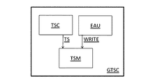
コアはさらに、コア入力(IN)にある対象イベント(EV_INT)を選択するイベント設定部(EAU)を備えるとしてよい。このイベント設定部を用いることによって、ユーザが関心を持たない大量のイベント時間データを記録することを回避できるとしてよい。コアの入力(CI)に有効なイベント(EV)がある場合には、イベント設定部(EAU)は、タイム・スタンプ・メモリ(TSM)に書き込みコマンドを発行する。図5に示すように、イベント設定部(EAU)からの書き込みコマンド(WRITE)に応じて、タイム・スタンプ・メモリ(TSM)は、タイム・スタンプ・カウンタ(TSC)の現在のステータス(TS)を記録する。 The core may further include an event setting unit (EAU) that selects a target event (EV_INT) at the core input (IN). By using this event setting unit, it may be possible to avoid recording a large amount of event time data that the user is not interested in. When there is a valid event (EV) in the core input (CI), the event setting unit (EAU) issues a write command to the time stamp memory (TSM). As shown in FIG. 5, in response to a write command (WRITE) from the event setting unit (EAU), the time stamp memory (TSM) changes the current status (TS) of the time stamp counter (TSC). Record.
本発明の一実施形態によると、図4に示すグローバル・タイム・スタンプ・コア(GTSC)は、GTS_CLOCK信号のエッジをカウントし、且つ、GTS_SYNC信号によって初期値にリセットされるタイム・スタンプ・カウンタ(TSC)を備える。 According to one embodiment of the present invention, the global time stamp core (GTSC) shown in FIG. 4 counts the edges of the GTS_CLOCK signal and is reset to an initial value by the GTS_SYNC signal ( TSC).
システムが備えるいずれのタイム・スタンプ・カウンタ(TSC)も、同時に、同じタイムスタンプ(TS)を示すとしてよい。このため、いずれのシステムピンであっても、同時に現れるイベント(EV)については、関連するタイム・スタンプ・メモリ(TSM)に同じタイム・スタンプ(TS)が書き込まれることになるとしてよい。 Any time stamp counter (TSC) provided in the system may simultaneously indicate the same time stamp (TS). For this reason, the same time stamp (TS) may be written to the associated time stamp memory (TSM) for events (EV) that appear at the same time in any system pin.
図5は、本発明に係る新しいシステム時間測定方式を説明するための、グローバル・タイム・スタンプ・コア(GTSC)を示す概略ブロック図である。 FIG. 5 is a schematic block diagram showing a global time stamp core (GTSC) for explaining a new system time measurement method according to the present invention.
本発明はさらに、自動試験装置で利用される方法を提供する。当該方法は、自動試験装置で利用されるグローバル・タイム・スタンプ・コア(GTSC)のための方法を含む。当該方法は、少なくとも2つの情報を受信する段階を備える。受信する2つの情報のうち第1の情報はクロック情報(CL_INF)を含み、受信する2つの情報のうち第2の情報は同期情報(SYNC_INF)を含む。 The present invention further provides a method for use in an automatic test apparatus. The method includes a method for a global time stamp core (GTSC) utilized in automated test equipment. The method comprises receiving at least two pieces of information. Of the two pieces of received information, the first information includes clock information (CL_INF), and among the two pieces of received information, the second information includes synchronization information (SYNC_INF).
上述した自動試験装置で用いられるグローバル・タイム・スタンプ・コア(GTSC)のための方法はさらに、複数のグローバル・タイム・スタンプ・コア(GTSC)によるデータ取得を同期させるべく、コア入力(IN)においてイベント(EV)を受信する段階を備える。 The method for global time stamp core (GTSC) used in the automatic test equipment described above further includes a core input (IN) to synchronize data acquisition by multiple global time stamp cores (GTSC). Receiving an event (EV).
上述した自動試験装置で用いられるグローバル・タイム・スタンプ・コア(GTSC)のための方法はさらに、コア入力(CI)で受信されるイベント(EV)から対象イベント(EV_INT)を決定する段階を備える。 The method for global time stamp core (GTSC) used in the automatic test equipment described above further comprises determining a target event (EV_INT) from an event (EV) received at the core input (CI). .
上述した自動試験装置で用いられるグローバル・タイム・スタンプ・コア(GTSC)のための方法はさらに、対象イベント(EV_INT)が決定されると、クロック情報(CL_INF)に対応するタイム・スタンプ・カウンタ(TSC)の現在のステータス(TS)を記録するようにタイム・スタンプ・メモリ(TSM)に指示する段階を備える。 The method for global time stamp core (GTSC) used in the automatic test apparatus described above further includes a time stamp counter (CL_INF) corresponding to clock information (CL_INF) when the target event (EV_INT) is determined. Instructing the time stamp memory (TSM) to record the current status (TS) of the TSC).
本発明の一実施形態によると、上述した自動試験装置で用いられるグローバル・タイム・スタンプ・コア(GTSC)のための方法では、タイム・スタンプ・カウンタ(TSC)は、同期情報(SYNC_INF)のリセット情報に応じてリセットされるとしてよい。 According to an embodiment of the present invention, in the method for the global time stamp core (GTSC) used in the automatic test apparatus described above, the time stamp counter (TSC) resets the synchronization information (SYNC_INF). It may be reset according to information.
当業者であれば容易に、上述したさまざまな方法のステップは、プログラミングされたコンピュータで実行し得るものと認めるであろう。本明細書において、一部の実施形態は、機械またはコンピュータによる読み取りが可能で、機械実行可能命令またはコンピュータ実行可能命令から成るプログラムを符号化するプログラム格納装置、例えば、デジタルデータ格納媒体をも含むものとする。上記命令は、上述した方法のステップの一部または全てを実行する。プログラム格納装置は、例えば、デジタルメモリ、磁気ディスクおよび磁気テープ等の磁気格納媒体、ハードドライブ、または、光学的に読出可能なデジタルデータ格納媒体であってよい。実施形態はさらに、上述の方法のステップを実行するようにプログラミングされたコンピュータを含むものである。 Those skilled in the art will readily appreciate that the various method steps described above may be performed on a programmed computer. As used herein, some embodiments also include a program storage device, eg, a digital data storage medium, that is readable by a machine or computer and that encodes a program comprising machine-executable instructions or computer-executable instructions. Shall be. The instructions perform some or all of the method steps described above. The program storage device may be, for example, a digital storage, a magnetic storage medium such as a magnetic disk and a magnetic tape, a hard drive, or an optically readable digital data storage medium. Embodiments further include a computer programmed to perform the steps of the method described above.
明細書および図面は単に、本発明の原理を説明するためのものである。このため、当業者であれば、本明細書に明示的に説明または図示していなくても、本発明の原理を具現化して本発明の意図および範囲内に含まれるさまざまな構成を考案することができると考えられる。さらに、本明細書に記載した例は全て、読み手が本発明の原理および関連技術分野の発展のために発明者が考案した概念を理解する上で助けになるように明らかに説明のみを主な目的としており、具体的に記載した例および条件に限定されるものではないと解釈されたい。さらに、本明細書の説明はすべて、本発明の原理、側面および実施形態、ならびに、本発明の具体例を記載しており、その均等物を含むものとする。 The specification and drawings are merely illustrative of the principles of the invention. For this reason, those skilled in the art will devise various configurations that fall within the spirit and scope of the present invention by embodying the principles of the present invention, even if not explicitly described or illustrated herein. It is thought that you can. Moreover, all examples described herein are primarily intended to be illustrative only to assist the reader in understanding the principles of the invention and the concepts devised by the inventor for the development of the related art. It should be construed as intended and not limited to the specifically described examples and conditions. Furthermore, all descriptions in this specification describe principles, aspects and embodiments of the invention, as well as specific examples of the invention and are intended to include equivalents thereof.
図面に図示したさまざまな構成要素の機能は、専用ハードウェアおよびソフトウェアを実行可能なハードウェアを適切なソフトウェアと共に用いることで提供されるとしてよい。この機能は、プロセッサによって提供される場合、単一の専用プロセッサ、単一の共有プロセッサ、または、一部が共有される複数のプロセッサによって提供されるとしてよい。さらに、「プロセッサ」または「コントローラ」という用語を明示的に用いる場合、ソフトウェアを実行可能なハードウェアのみを意味するものと解釈されるべきではなく、これらに限定されないが、デジタルシグナルプロセッサ(DSP)ハードウェア、ネットワークプロセッサ、特定用途向け集積回路(ASIC)、フィールドプログラマブルゲートアレイ(FPGA)、ソフトウェア格納用のリードオンリーメモリ(ROM)、ランダムアクセスメモリ(RAM)、不揮発性ストレージを暗示的に含むものとしてよい。その他のハードウェア、従来および/またはカスタムメイドのハードウェアも含むとしてよい。同様に、図面に図示したいずれのスイッチも概念を示したものに過ぎない。その機能は、プログラムロジックの動作によって、専用ロジックによって、プログラム制御ロジックおよび専用ロジックのやり取りによって、または、手動で実現するとしてよく、上記の説明からより具体的に理解されるであろうが、実装する際に特定の方法を選択することが可能である。 The functions of the various components illustrated in the drawings may be provided using dedicated hardware and hardware capable of executing software, with appropriate software. When provided by a processor, this functionality may be provided by a single dedicated processor, a single shared processor, or multiple processors that are partially shared. Further, the explicit use of the terms “processor” or “controller” should not be construed to mean only hardware capable of executing software, but is not limited to digital signal processors (DSPs). Implicitly includes hardware, network processor, application specific integrated circuit (ASIC), field programmable gate array (FPGA), read only memory (ROM) for software storage, random access memory (RAM), non-volatile storage As good as Other hardware may also be included, conventional and / or custom-made hardware. Similarly, any switches shown in the drawings are conceptual only. Its function may be realized by the operation of program logic, by dedicated logic, by exchange of program control logic and dedicated logic, or manually, as will be more specifically understood from the above description, It is possible to select a specific method when doing so.
当業者におかれては本明細書で言及したブロック図はいずれも本発明の原理を具現化する回路の一例を概念的に示したものと理解されたい。同様に、フローチャート、フロー図、状態遷移図、擬似コード等は、コンピュータ可読媒体において実質的に表現され、明示的に図示するか否かに関わらずコンピュータまたはプロセッサによって実行されるさまざまなプロセスを表したものと理解されたい。 It should be understood by those skilled in the art that any of the block diagrams referred to herein conceptually illustrates an example of a circuit that embodies the principles of the present invention. Similarly, flowcharts, flow diagrams, state transition diagrams, pseudocode, etc. are substantially represented in a computer-readable medium and represent various processes performed by a computer or processor, whether or not explicitly illustrated. I want you to understand.
Claims (10)
一のシステムモジュール(SYSMOD)は、一の時間測定部(TMU)を備え、
前記時間測定部(TMU)は、グローバル・タイム・スタンプ・モジュール(GTSM)を備え、
前記グローバル・タイム・スタンプ・モジュール(GTSM)は、複数のグローバル・タイム・スタンプ・コア(GTSC)を備え、
前記複数のグローバル・タイム・スタンプ・コア(GTSC)はそれぞれ、
少なくとも2つの情報を受信する情報受信部と、
複数のグローバル・タイム・スタンプ・コア(GTSC)によるデータ取得を同期させるべく、コア入力(IN)においてイベント(EV)を受信するイベント受信部と、
前記コア入力(IN)で受信される前記イベント(EV)から対象イベント(EV_INT)を決定するイベント決定部と、
対象イベント(EV_INT)が決定されると、クロック情報(CL_INF)に対応するタイム・スタンプ・カウンタ(TSC)の現在のステータス(TS)を記録するようにタイム・スタンプ・メモリ(TSM)に指示する指示部と
を備え、
受信する前記2つの情報のうち第1の情報は前記クロック情報(CL_INF)を含み、前記受信する2つの情報のうち第2の情報は同期情報(SYNC_INF)を含み、
前記グローバル・タイム・スタンプ・モジュール(GTSM)はさらに、
前記複数のグローバル・タイム・スタンプ・コア(GTSC)に共通時間基準を供給することによって、前記複数のグローバル・タイム・スタンプ・コア(GTSC)によるデータ取得を同期させる供給部を備える、装置。 An apparatus used in an automatic test apparatus including a plurality of system modules (SYSMOD),
One system module (SYSMOD) includes one time measurement unit (TMU),
The time measurement unit (TMU) includes a global time stamp module (GTSM),
The global time stamp module (GTSM) comprises a plurality of global time stamp cores (GTSC),
Each of the plurality of global time stamp cores (GTSCs)
An information receiving unit for receiving at least two pieces of information;
An event receiver for receiving an event (EV) at a core input (IN) to synchronize data acquisition by a plurality of global time stamp cores (GTSC);
An event determination unit that determines a target event (EV_INT) from the event (EV) received at the core input (IN);
When the target event (EV_INT) is determined, the time stamp memory (TSM) is instructed to record the current status (TS) of the time stamp counter (TSC) corresponding to the clock information (CL_INF). An indicator and
Of the two information to be received, the first information includes the clock information (CL_INF), and among the two information to be received, the second information includes synchronization information (SYNC_INF),
The global time stamp module (GTSM) further includes
An apparatus comprising: a supply for synchronizing data acquisition by the plurality of global time stamp cores (GTSC) by supplying a common time reference to the plurality of global time stamp cores (GTSC).
前記複数のグローバル・タイム・スタンプ・コア(GTSC)はそれぞれ、
少なくとも2つの情報を受信する段階と、
複数のグローバル・タイム・スタンプ・コア(GTSC)によるデータ取得を同期させるべく、コア入力(CI)においてイベント(EV)を受信する段階と、
前記コア入力(CI)で受信される前記イベント(EV)から対象イベント(EV_INT)を決定する段階と、
対象イベント(EV_INT)が決定されると、クロック情報(CL_INF)に対応するタイム・スタンプ・カウンタ(TSC)の現在のステータス(TS)を記録するようにタイム・スタンプ・メモリ(TSM)に指示する段階と
を備え、
前記グローバル・タイム・スタンプ・モジュール(GTSM)のための方法はさらに、
前記複数のグローバル・タイム・スタンプ・コア(GTSC)に共通時間基準を供給することによって、前記複数のグローバル・タイム・スタンプ・コア(GTSC)によるデータ取得を同期させる段階を備え、
受信する前記2つの情報のうち第1の情報は前記クロック情報(CL_INF)を含み、前記受信する2つの情報のうち第2の情報は同期情報(SYNC_INF)を含む方法。 A method for a global time stamp module (GTSM) used in an automatic test equipment comprising a plurality of global time stamp cores (GTSC), comprising:
Each of the plurality of global time stamp cores (GTSCs)
Receiving at least two pieces of information;
Receiving an event (EV) at a core input (CI) to synchronize data acquisition by multiple global time stamp cores (GTSCs);
Determining a target event (EV_INT) from the event (EV) received at the core input (CI);
When the target event (EV_INT) is determined, the time stamp memory (TSM) is instructed to record the current status (TS) of the time stamp counter (TSC) corresponding to the clock information (CL_INF). With steps and
The method for the global time stamp module (GTSM) further comprises:
Synchronizing data acquisition by the plurality of global time stamp cores (GTSC) by providing a common time reference to the plurality of global time stamp cores (GTSC);
The first information of the two information to be received includes the clock information (CL_INF), and the second information of the two information to be received includes synchronization information (SYNC_INF).
少なくとも2つの情報を受信する段階と、
複数のグローバル・タイム・スタンプ・コア(GTSC)によるデータ取得を同期させるべく、コア入力(CI)においてイベント(EV)を受信する段階と、
前記コア入力(CI)で受信される前記イベント(EV)から対象イベント(EV_INT)を決定する段階と、
対象イベント(EV_INT)が決定されると、クロック情報(CL_INF)に対応するタイム・スタンプ・カウンタ(TSC)の現在のステータス(TS)を記録するようにタイム・スタンプ・メモリ(TSM)に指示する段階と
を備え、
受信する前記2つの情報のうち第1の情報は前記クロック情報(CL_INF)を含み、前記受信する2つの情報のうち第2の情報は同期情報(SYNC_INF)を含む、方法。 A method for Global Time Stamp Core (GTSC) used in automatic test equipment,
Receiving at least two pieces of information;
Receiving an event (EV) at a core input (CI) to synchronize data acquisition by multiple global time stamp cores (GTSCs);
Determining a target event (EV_INT) from the event (EV) received at the core input (CI);
When the target event (EV_INT) is determined, the time stamp memory (TSM) is instructed to record the current status (TS) of the time stamp counter (TSC) corresponding to the clock information (CL_INF). With steps and
The first information of the two information to be received includes the clock information (CL_INF), and the second information of the two information to be received includes synchronization information (SYNC_INF).
請求項9に記載の方法。 The method according to claim 9, wherein the time stamp counter (TSC) is reset in response to reset information of the synchronization information (SYNC_INF).
Applications Claiming Priority (4)
| Application Number | Priority Date | Filing Date | Title |
|---|---|---|---|
| US36351510P | 2010-07-12 | 2010-07-12 | |
| US61/363,515 | 2010-07-12 | ||
| US13/013,495 US8938370B2 (en) | 2010-07-12 | 2011-01-25 | Method and apparatus for complex time measurements |
| US13/013,495 | 2011-01-25 |
Publications (2)
| Publication Number | Publication Date |
|---|---|
| JP2012021981A true JP2012021981A (en) | 2012-02-02 |
| JP5695985B2 JP5695985B2 (en) | 2015-04-08 |
Family
ID=45439196
Family Applications (1)
| Application Number | Title | Priority Date | Filing Date |
|---|---|---|---|
| JP2011144248A Active JP5695985B2 (en) | 2010-07-12 | 2011-06-29 | Method and apparatus for complex time measurement |
Country Status (4)
| Country | Link |
|---|---|
| US (1) | US8938370B2 (en) |
| JP (1) | JP5695985B2 (en) |
| DE (1) | DE102011051724B4 (en) |
| TW (1) | TWI426287B (en) |
Families Citing this family (4)
| Publication number | Priority date | Publication date | Assignee | Title |
|---|---|---|---|---|
| WO2012139042A2 (en) | 2011-04-08 | 2012-10-11 | Dexcom, Inc. | Systems and methods for processing and transmitting sensor data |
| CN116170766A (en) | 2013-11-07 | 2023-05-26 | 德克斯康公司 | Systems and methods for emission and continuous monitoring of analyte values |
| US9891966B2 (en) | 2015-02-10 | 2018-02-13 | Red Hat, Inc. | Idempotent mode of executing commands triggered by complex event processing |
| US10423468B2 (en) * | 2015-02-10 | 2019-09-24 | Red Hat, Inc. | Complex event processing using pseudo-clock |
Citations (5)
| Publication number | Priority date | Publication date | Assignee | Title |
|---|---|---|---|---|
| JPH11190766A (en) * | 1997-10-14 | 1999-07-13 | Schlumberger Technol Inc | Measurement for signal at tester system |
| JP2003535344A (en) * | 2000-05-31 | 2003-11-25 | テラダイン・インコーポレーテッド | ATE timing measuring apparatus and method |
| JP2008505318A (en) * | 2004-06-30 | 2008-02-21 | テラダイン・インコーポレーテッド | Precision time measuring apparatus and method |
| JP2008202956A (en) * | 2007-02-16 | 2008-09-04 | Yokogawa Electric Corp | Semiconductor test equipment |
| JP2009121924A (en) * | 2007-11-14 | 2009-06-04 | Yokogawa Electric Corp | Semiconductor test equipment |
Family Cites Families (3)
| Publication number | Priority date | Publication date | Assignee | Title |
|---|---|---|---|---|
| US5025205A (en) | 1989-06-22 | 1991-06-18 | Texas Instruments Incorporated | Reconfigurable architecture for logic test system |
| JP3368572B2 (en) * | 1995-09-29 | 2003-01-20 | 株式会社アドバンテスト | Period generator |
| US20090089623A1 (en) | 2007-09-28 | 2009-04-02 | Agilent Technologies, Inc | Event timing analyzer for a system of instruments and method of analyzing event timing in a system of intruments |
-
2011
- 2011-01-25 US US13/013,495 patent/US8938370B2/en active Active
- 2011-06-27 TW TW100122439A patent/TWI426287B/en active
- 2011-06-29 JP JP2011144248A patent/JP5695985B2/en active Active
- 2011-07-11 DE DE201110051724 patent/DE102011051724B4/en active Active
Patent Citations (5)
| Publication number | Priority date | Publication date | Assignee | Title |
|---|---|---|---|---|
| JPH11190766A (en) * | 1997-10-14 | 1999-07-13 | Schlumberger Technol Inc | Measurement for signal at tester system |
| JP2003535344A (en) * | 2000-05-31 | 2003-11-25 | テラダイン・インコーポレーテッド | ATE timing measuring apparatus and method |
| JP2008505318A (en) * | 2004-06-30 | 2008-02-21 | テラダイン・インコーポレーテッド | Precision time measuring apparatus and method |
| JP2008202956A (en) * | 2007-02-16 | 2008-09-04 | Yokogawa Electric Corp | Semiconductor test equipment |
| JP2009121924A (en) * | 2007-11-14 | 2009-06-04 | Yokogawa Electric Corp | Semiconductor test equipment |
Also Published As
| Publication number | Publication date |
|---|---|
| TWI426287B (en) | 2014-02-11 |
| US20120010857A1 (en) | 2012-01-12 |
| DE102011051724B4 (en) | 2014-03-13 |
| US8938370B2 (en) | 2015-01-20 |
| DE102011051724A1 (en) | 2012-03-01 |
| TW201202725A (en) | 2012-01-16 |
| JP5695985B2 (en) | 2015-04-08 |
Similar Documents
| Publication | Publication Date | Title |
|---|---|---|
| JP5389357B2 (en) | Time measurement using a phase-shifted periodic waveform | |
| JP5695985B2 (en) | Method and apparatus for complex time measurement | |
| JPWO2008136301A1 (en) | Test apparatus and test method | |
| CN115291090B (en) | Chip tester signal delay measurement method, device and computer equipment | |
| JP4319146B2 (en) | Semiconductor test equipment | |
| KR19990037034A (en) | Signal measuring device in tester system | |
| CN111756593B (en) | Self-test method and test method for synchronization accuracy of time synchronization system | |
| CN107144781A (en) | Measuring system with digital edge detection trigger circuit | |
| JP2012083342A (en) | Measuring apparatus, measuring method, testing device and program | |
| WO2007138814A1 (en) | Testing apparatus and test module | |
| JP4446892B2 (en) | Semiconductor test equipment | |
| US8144828B2 (en) | Counter/timer functionality in data acquisition systems | |
| JP3633988B2 (en) | Timing edge generation circuit for semiconductor IC test equipment | |
| KR102148043B1 (en) | Flexible test site synchronization | |
| JP4425537B2 (en) | Test apparatus and test method | |
| KR100995812B1 (en) | Test device, test method, and program | |
| JP2020193899A (en) | Test equipment | |
| JP5274365B2 (en) | Signal measuring apparatus, signal measuring method, recording medium, and test apparatus | |
| JP5210646B2 (en) | Apparatus, method, and test apparatus for detecting change point of signal under measurement | |
| TW533421B (en) | Scan vector support for event based test system | |
| WO2008075702A1 (en) | Signal measuring device, and signal measuring method | |
| Polzer et al. | Metastability characterization for Muller C-elements | |
| JP3601680B2 (en) | IC tester | |
| CN101923107B (en) | Measure and represent the method and system of the measured value of the limit according to another measurement result | |
| TW200928376A (en) | Adjustable test pattern results latency |
Legal Events
| Date | Code | Title | Description |
|---|---|---|---|
| A621 | Written request for application examination |
Free format text: JAPANESE INTERMEDIATE CODE: A621 Effective date: 20120807 |
|
| A977 | Report on retrieval |
Free format text: JAPANESE INTERMEDIATE CODE: A971007 Effective date: 20130520 |
|
| A131 | Notification of reasons for refusal |
Free format text: JAPANESE INTERMEDIATE CODE: A131 Effective date: 20130528 |
|
| A131 | Notification of reasons for refusal |
Free format text: JAPANESE INTERMEDIATE CODE: A131 Effective date: 20140513 |
|
| A521 | Request for written amendment filed |
Free format text: JAPANESE INTERMEDIATE CODE: A523 Effective date: 20140708 |
|
| TRDD | Decision of grant or rejection written | ||
| A01 | Written decision to grant a patent or to grant a registration (utility model) |
Free format text: JAPANESE INTERMEDIATE CODE: A01 Effective date: 20150127 |
|
| A61 | First payment of annual fees (during grant procedure) |
Free format text: JAPANESE INTERMEDIATE CODE: A61 Effective date: 20150209 |
|
| R150 | Certificate of patent or registration of utility model |
Ref document number: 5695985 Country of ref document: JP Free format text: JAPANESE INTERMEDIATE CODE: R150 |
|
| R250 | Receipt of annual fees |
Free format text: JAPANESE INTERMEDIATE CODE: R250 |
|
| R250 | Receipt of annual fees |
Free format text: JAPANESE INTERMEDIATE CODE: R250 |
|
| R250 | Receipt of annual fees |
Free format text: JAPANESE INTERMEDIATE CODE: R250 |
|
| R250 | Receipt of annual fees |
Free format text: JAPANESE INTERMEDIATE CODE: R250 |
|
| R250 | Receipt of annual fees |
Free format text: JAPANESE INTERMEDIATE CODE: R250 |
|
| R250 | Receipt of annual fees |
Free format text: JAPANESE INTERMEDIATE CODE: R250 |
|
| R250 | Receipt of annual fees |
Free format text: JAPANESE INTERMEDIATE CODE: R250 |
|
| R250 | Receipt of annual fees |
Free format text: JAPANESE INTERMEDIATE CODE: R250 |
|
| R250 | Receipt of annual fees |
Free format text: JAPANESE INTERMEDIATE CODE: R250 |