JP2012043936A - Solar cell device - Google Patents
Solar cell device Download PDFInfo
- Publication number
- JP2012043936A JP2012043936A JP2010183055A JP2010183055A JP2012043936A JP 2012043936 A JP2012043936 A JP 2012043936A JP 2010183055 A JP2010183055 A JP 2010183055A JP 2010183055 A JP2010183055 A JP 2010183055A JP 2012043936 A JP2012043936 A JP 2012043936A
- Authority
- JP
- Japan
- Prior art keywords
- solar cell
- posture
- panels
- cell panels
- cell device
- Prior art date
- Legal status (The legal status is an assumption and is not a legal conclusion. Google has not performed a legal analysis and makes no representation as to the accuracy of the status listed.)
- Pending
Links
- 239000000428 dust Substances 0.000 abstract description 12
- 238000010248 power generation Methods 0.000 abstract description 11
- 239000002245 particle Substances 0.000 abstract description 10
- 230000006378 damage Effects 0.000 abstract description 4
- 230000006866 deterioration Effects 0.000 abstract description 3
- 230000036544 posture Effects 0.000 description 58
- 230000004048 modification Effects 0.000 description 3
- 238000012986 modification Methods 0.000 description 3
- 230000005540 biological transmission Effects 0.000 description 2
- 206010037660 Pyrexia Diseases 0.000 description 1
- 230000020169 heat generation Effects 0.000 description 1
Images


Classifications
-
- Y—GENERAL TAGGING OF NEW TECHNOLOGICAL DEVELOPMENTS; GENERAL TAGGING OF CROSS-SECTIONAL TECHNOLOGIES SPANNING OVER SEVERAL SECTIONS OF THE IPC; TECHNICAL SUBJECTS COVERED BY FORMER USPC CROSS-REFERENCE ART COLLECTIONS [XRACs] AND DIGESTS
- Y02—TECHNOLOGIES OR APPLICATIONS FOR MITIGATION OR ADAPTATION AGAINST CLIMATE CHANGE
- Y02E—REDUCTION OF GREENHOUSE GAS [GHG] EMISSIONS, RELATED TO ENERGY GENERATION, TRANSMISSION OR DISTRIBUTION
- Y02E10/00—Energy generation through renewable energy sources
- Y02E10/50—Photovoltaic [PV] energy
Landscapes
- Photovoltaic Devices (AREA)
Abstract
Description
この発明は、砂漠地域等、劣悪な気候条件での使用に適した太陽電池装置に関する。 The present invention relates to a solar cell device suitable for use in poor climatic conditions such as desert areas.
従来の発電装置として、特許文献1に開示のものがある。特許文献1では、回転体の上面に太陽電池が張設され、回転体の外周部には複数の受風羽根が定間隔で配設されている。そして、受風羽根に受けた風力により、回転体が回転するようになっている。 There exists a thing disclosed in patent document 1 as a conventional electric power generating apparatus. In Patent Document 1, a solar cell is stretched on the upper surface of a rotating body, and a plurality of wind receiving blades are arranged at regular intervals on the outer periphery of the rotating body. The rotating body is rotated by the wind force received by the wind receiving blades.
しかしながら、特許文献1に開示の発電装置では、回転体の上面に太陽電池が張設されている。このため、強風時には、太陽電池が風による大きな力を受けてしまい、破損に至る恐れがある。また、砂漠地域等で砂塵が舞っているような場合には、砂塵が太陽電池上に乗ってしまい、発電効率を下げてしまう恐れがある。 However, in the power generation device disclosed in Patent Document 1, a solar cell is stretched on the upper surface of the rotating body. For this reason, at the time of a strong wind, a solar cell receives the big force by a wind, and there exists a possibility of damaging. In addition, when dust is dancing in a desert area or the like, the dust may get on the solar cell and reduce power generation efficiency.
そこで、本発明は、強風等による破壊を抑制し、かつ、空中を舞う砂塵等の粒子による発電効率の低下を抑制することを目的とする。 Therefore, an object of the present invention is to suppress destruction due to strong winds and the like, and to suppress a decrease in power generation efficiency due to particles such as dust flying in the air.
上記課題を解決するため、第1の態様は、回転軸周りに回転可能に支持された回転体と、前記回転体に、前記回転軸を中心として放射状に延出する開姿勢と前記回転軸に沿って延びる閉姿勢との間で姿勢変更可能に支持された複数の太陽電池パネルと、前記複数の太陽電池パネルを前記閉姿勢と前記開姿勢との間で姿勢変更させる開閉機構部と備える。 In order to solve the above-described problem, the first aspect includes a rotating body that is rotatably supported around a rotation axis, an opening posture that extends radially around the rotation axis, and the rotation axis. A plurality of solar cell panels that are supported so as to be able to change their posture between a closed posture that extends along; and an opening / closing mechanism that changes the posture of the plurality of solar cell panels between the closed posture and the open posture.
第2の態様は、第1の態様に係る太陽電池装置であって、前記回転体を前記複数の太陽電池パネルと共に回転させる回転駆動機構部をさらに備える。 A 2nd aspect is a solar cell apparatus which concerns on a 1st aspect, Comprising: The rotation drive mechanism part which rotates the said rotary body with these solar cell panels is further provided.
第3の態様は、第1又は第2の態様に係る太陽電池装置であって、前記複数の太陽電池パネルは、前記閉姿勢で複数層となるように収納され、前記開姿勢で少なくとも先端部が相互に重なり合わないように開くものである。 A 3rd aspect is a solar cell apparatus which concerns on a 1st or 2nd aspect, Comprising: These solar cell panels are accommodated so that it may become two or more layers by the said closed attitude | position, At least a front-end | tip part by the said open attitude | position Are opened so as not to overlap each other.
第1の態様によると、複数の太陽電池パネルを閉姿勢にすることで、複数の太陽電池パネルが風を受け難くなる。このため、強風等による破壊を抑制することができる。しかも、複数の太陽電池パネルを開姿勢にした状態で、当該複数の太陽電池パネルを回転させることで、空中を舞う砂塵等の粒子が太陽電池パネルから落される。これにより、空中を舞う砂塵等の粒子による発電効率の低下も抑制することができる。 According to the 1st aspect, it becomes difficult for a several solar cell panel to receive a wind by making a several solar cell panel into a closed attitude | position. For this reason, the destruction by a strong wind etc. can be suppressed. Moreover, by rotating the plurality of solar cell panels in a state where the plurality of solar cell panels are in the open posture, particles such as dust flying in the air are dropped from the solar cell panel. Thereby, the fall of the power generation efficiency by particles, such as dust which flies in the air, can also be controlled.
第2の態様によると、複数の太陽電池パネルを回転駆動することにより、空中を舞う砂塵等の粒子がより確実に太陽電池パネルから落される。これにより、空中を舞う砂塵等の粒子による発電効率の低下をより確実に抑制することができる。 According to the second aspect, by rotating and driving the plurality of solar cell panels, particles such as dust flying in the air are more reliably dropped from the solar cell panel. Thereby, the fall of the power generation efficiency by particles, such as dust which flies in the air, can be suppressed more reliably.
第3の態様によると、閉姿勢でなるべくコンパクトにでき、開姿勢で太陽光を受けることができる太陽電池パネルの面積をなるべく大きくすることができる。 According to the third aspect, the area of the solar cell panel that can be made as compact as possible in the closed position and can receive sunlight in the open position can be increased as much as possible.
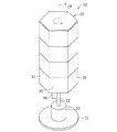
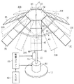
以下、実施形態に係る太陽電池装置について説明する。図1は太陽電池パネル30が閉じた状態での太陽電池装置10を示す斜視図であり、図2は太陽電池パネル30が開いた状態での太陽電池装置10を示す斜視図であり、図3は太陽電池装置10の部分拡大説明図である。
Hereinafter, the solar cell device according to the embodiment will be described. 1 is a perspective view showing the
この太陽電池装置10は、回転体20と、複数の太陽電池パネル30と、開閉機構部40と、回転駆動機構部50とを備えている。
The
回転体20は、鉛直軸に沿った回転軸X周りに回転可能に支持されている。
The rotating
より具体的には、回転体20は、基台12上で回転駆動機構部50を介して回転可能に支持されている。ここでは、基台12は、地面或は建物の屋上等の水平面上に一定姿勢で載置可能な形状に形成されている。図1では、基台12は円板上に形成されているが、その他、多角形板状、複数の脚によって支える構成等であってもよい。また、基台は、建築物の壁、屋上等にボルト等で固定される構成であってもよい。
More specifically, the rotating
回転体20は、主軸部22と回転板部24とを有している。主軸部22は、基台12上で回転駆動機構部50を介して鉛直姿勢で回転可能に支持されている。回転板部24は、主軸部22の上端部に取付けられており、主軸部22と共に回転するように構成されている。ここでは、回転板部24は、多角形板状(好ましくは正多角形板状、ここでは、正六角形板状)に形成されており、その中心部に、主軸部22が連結されている。回転板部24は、孔が形成された板、若しくは、棒状部材を組合わせた枠組構造とするとよい。これにより、太陽電池装置10内に風が通りやすくなり、太陽電池装置10の温度上昇を抑制することができる。
The rotating
各太陽電池パネル30は、方形板状、ここでは、細長い方形板状に形成されている。そして、太陽電池パネル30の一主面である受光面に太陽光等の光が照射されることで、各太陽電池パネル30において発電がなされる。そして、複数の太陽電池パネル30において生じた電力が、太陽光発電制御装置等を介して総発電電力として取出されるようになっている。
Each
上記各太陽電池パネル30は、上記回転板部24の外周囲に姿勢変更可能に支持されている。より具体的には、受光面を外向きにした姿勢で、太陽電池パネル30の一方側の短辺部分が、回転板部24の各辺部分に沿って配設され、ヒンジ部32を介して姿勢変更可能に連結支持されている。太陽電池パネル30が主軸部22に沿って鉛直方向に沿って延在する姿勢が閉姿勢(図1参照)であり、太陽電池パネル30がヒンジ部32を中心として主軸部22から遠ざかる方向に傾いた姿勢が開姿勢(図2参照)であり、太陽電池パネル30は両姿勢の間で姿勢変更可能とされている。そして、複数の太陽電池パネル30のそれぞれが回転板部24周りに姿勢変更可能に取付けられており、複数の太陽電池パネル30の全てが開姿勢になると、当該複数の太陽電池パネル30が回転軸Xを中心として放射状に延出する状態となる。また、複数の太陽電池パネル30の全てが閉姿勢になると、当該複数の太陽電池パネル30が回転軸Xに沿って延在し、主軸部22の周りを閉鎖するように覆うようになる。複数の太陽電池パネル30は、上記開姿勢と閉姿勢との間の中間の姿勢で維持されてもよい。
Each of the
開閉機構部40は、複数の太陽電池パネル30を上記閉姿勢と開姿勢との間で姿勢変更させるように構成されている。ここでは、開閉機構部40は、主軸部22に沿って移動可能な可動部42と、各太陽電池パネル30と可動部とを連結する複数の連結棒状部44とを有している。各連結棒状部44の一端部は可動部42に揺動可能に連結され、連結棒状部44の他端部は各太陽電池パネル30の内面の長手方向中間部に揺動可能に連結されている。そして、可動部42を下方に移動させると、各連結棒状部44の他端部が主軸部22に沿って下方に移動すると共に、各連結棒状部44の一端部が主軸部22側に向けて引込まれる。これにより、各太陽電池パネル30が閉姿勢に姿勢変更される(図1及び図3の実線参照)。一方、可動部42を上方に移動させると、各連結棒状部44の他端部が主軸部22に沿って上方に移動すると共に、各連結棒状部44の一端部が主軸部22から遠ざかる外方に向けて押込まれる。これにより、各太陽電池パネル30が開姿勢に姿勢変更される(図1及び図3の2点鎖線)。
The opening /
また、本実施形態では、開閉機構部40は、複数の太陽電池パネル30を閉姿勢と開姿勢との間で姿勢変更駆動する開閉駆動部としてリニアアクチュエータ48を有している。リニアアクチュエータ48としては、リニアモータ、油圧シリンダ、エアシリンダ等を用いることができる。そして、リニアアクチュエータ48は、進退駆動可能なロッド部49を有しており、主軸部22に取付けられている。また、ロッド部49の先端は、可動部42に連結されている。そして、リニアアクチュエータ48からロッド部49を進退駆動させることで、可動部42が主軸部22に沿って昇降移動し、その昇降に伴って複数の太陽電池パネル30が上記閉姿勢と開姿勢との間で姿勢変更駆動されるようになっている。
In the present embodiment, the opening /
もっとも、開閉駆動部としてのリニアアクチュエータ48を省略し、可動部42を人手等で昇降移動させるようにしてもよい。この場合、可動部42を上方及び下方の各位置で維持するために、主軸部22にボールプランジャ等の位置保持部品を設けておくとよい。
However, the
回転駆動機構部50は、上記回転体20を、複数の太陽電池パネル30と共に回転駆動する。ここでは、回転駆動機構部50は、モータと、そのモータの回転を主軸部22に伝達する回転伝達部とを有している。回転伝達部は、複数のギアの組合わせ等により構成され、モータの回転速度を適宜調整して主軸部22に伝達するように構成されている。この回転駆動機構部50は、基台12上に設けられ、主軸部22を回転駆動可能に支持している。そして、回転駆動機構部50によって、回転体20が回転駆動され、これに合わせて複数の太陽電池パネル30が回転駆動されるようになっている。
The rotational
もっとも、本回転駆動機構部50が省略され、主軸部22が基台12等にフリー回転可能に支持されていてもよい。
However, the
上記リニアアクチュエータ48及び回転駆動機構部50は、制御ユニット60の制御下、図示省略の駆動回路を介して駆動制御される。制御ユニット60は、CPU、ROMおよびRAM等を備える一般的なマイクロコンピュータであり、予め格納されたソフトウェアプログラム等に従ってリニアアクチュエータ48及び回転駆動機構部50を駆動制御する。ここでは、制御ユニット60にスイッチ等の入力部62が接続されており、当該入力部62を通じて入力される指令に従って、リニアアクチュエータ48及び回転駆動機構部50を駆動制御する。例えば、太陽電池パネル30を閉姿勢或は開姿勢にする指令が入力された場合には、当該指令に従ってリニアアクチュエータ48を駆動制御して可動部42を昇降移動させる。また、例えば、太陽電池パネル30を回転させる指令又は停止させる指令が入力された場合には、当該指令に従って回転駆動機構部50を回転駆動し、或は、回転停止させる。これにより、入力部62を通じて入力された指令に応じて、複数の太陽電池パネル30を開姿勢又は閉姿勢にすることができ、また、複数の太陽電池パネル30を回転状態又は回転停止状態にすることができる。
The
以上のように構成された太陽電池装置10によると、複数の太陽電池パネル30を閉姿勢にすることで、複数の太陽電池パネル30が風を受け難くなるため、強風時等には、複数の太陽電池パネル30を閉姿勢にしておくことで、太陽電池装置10の破壊を抑制することができる。なお、昼間には、複数の太陽電池パネル30を閉姿勢にした状態でも、太陽に面する側の太陽電池パネル30に太陽光が照射するため、発電を期待することができる。
According to the
一方、昼間の無風時或は弱風時等には、複数の太陽電池パネル30を開姿勢にしておくことで、複数の太陽電池パネル30によって有効に太陽光を受けて発電することができる。
On the other hand, when there is no wind or light winds in the daytime, the plurality of
この際、複数の太陽電池パネル30を閉姿勢にした状態で、当該複数の太陽電池パネル30を回転させることで、空中を舞う砂塵等の粒子が太陽電池パネル30から振り落される。これにより、空中を舞う砂塵等の粒子が太陽電池パネル30に付着することによる発電効率の低下も抑制することができる。
At this time, particles such as dust flying in the air are shaken off from the
特に、回転駆動機構部50によって複数の太陽電池パネル30の回転を継続した状態とすることにより、空中を舞う砂塵等の粒子がより確実に太陽電池パネル30から落される。これにより、空中を舞う砂塵等の粒子による発電効率の低下をより確実に抑制することができる。
In particular, when the rotation
また、発電時に、複数の太陽電池パネル30を回転させておくことで、各太陽電池パネル30が冷却されるため、発熱による劣化が抑制され、耐久性が向上する。しかも、太陽光が時間的に分散して複数の太陽電池パネル30に照射されるため、太陽電池パネル30の劣化度合が平均化され、太陽電池装置10全体としての寿命向上も図られる。
Moreover, since each
複数の太陽電池パネル30の回転は、複数の太陽電池パネル30が開姿勢であるときのみなされてもよいし、開姿勢及び閉姿勢の双方でなされてもよく、また、姿勢に関わりなく一時的になされてもよい。
The rotation of the plurality of
なお、上記した観点からすると、通常、強風時(好ましくは夜間も)には複数の太陽電池パネル30を閉姿勢にしておくことが好ましい。また、昼間でかつ無風時(好ましくは弱風時も)には複数の太陽電池パネル30を開姿勢にしておくことが好ましい。
From the above viewpoint, it is usually preferable to keep the plurality of
本実施形態では、本太陽電池装置10の利用者が昼夜、天候状況等に応じて入力部62を通じて操作することで、複数の太陽電池パネル30を閉姿勢及び開姿勢に切替え、また、回転状態及び回転停止状態に切替えることを想定している。
In the present embodiment, the user of the present
もっとも、風の強さを検出する風力センサ、太陽光等の光の照射の有無を検出する照度センサ等の出力に基づいて、強風時(好ましくは夜間も)には複数の太陽電池パネル30を閉姿勢にし、昼間でかつ無風時(好ましくは弱風時も)には複数の太陽電池パネル30を開姿勢にするようにしてもよい。その他の場合には、閉姿勢及び開姿勢のいずれであってもよい。
However, on the basis of the output of a wind sensor that detects the intensity of wind, an illuminance sensor that detects the presence or absence of light such as sunlight, a plurality of
なお、図4に示す変形例のように、上記複数の太陽電池パネル30の内側に別の複数の太陽電池パネル30Bが設けられていてもよい。この複数の太陽電池パネル30Bも、複数の太陽電池パネル30と同様に、開姿勢と閉姿勢との間で姿勢変更可能に支持されている。そして、複数の太陽電池パネル30Bは、複数の太陽電池パネル30と同期して開姿勢となり、複数の太陽電池パネル30Bの先端部と複数の太陽電池パネル30の先端部とが相互に重なり合わないように、広がるようになっている。
In addition, like the modification shown in FIG. 4, another plurality of
この変形例によると、複数の太陽電池パネル30、30Bが閉姿勢とされた状態ではなるべくコンパクトな構成にすることができると共に、複数の太陽電池パネル30、30Bを開姿勢にした状態では、太陽光等の光を受光する面積をなるべく大きくすることができ、発電電力量をより大きくすることができる。
According to this modification, the
なお、閉姿勢において、複数の太陽電池パネルが3層、或は、4層等、より多数層になるように設けてもよい。 Note that, in the closed position, a plurality of solar battery panels may be provided so as to have more layers such as three layers or four layers.
10 太陽電池装置
20 回転体
30、30B 太陽電池パネル
40 開閉機構部
48 リニアアクチュエータ
50 回転駆動機構部
DESCRIPTION OF
Claims (3)
前記回転体に、前記回転軸を中心として放射状に延出する開姿勢と前記回転軸に沿って延びる閉姿勢との間で姿勢変更可能に支持された複数の太陽電池パネルと、
前記複数の太陽電池パネルを前記閉姿勢と前記開姿勢との間で姿勢変更させる開閉機構部と、
を備える太陽電池装置。 A rotating body supported rotatably around a rotation axis;
A plurality of solar battery panels supported on the rotating body so as to be changeable between an open posture extending radially about the rotation axis and a closed posture extending along the rotation axis;
An opening / closing mechanism for changing the position of the plurality of solar battery panels between the closed position and the open position;
A solar cell device comprising:
前記回転体を前記複数の太陽電池パネルと共に回転させる回転駆動機構部をさらに備える太陽電池装置。 The solar cell device according to claim 1,
A solar cell device further comprising a rotation drive mechanism that rotates the rotating body together with the plurality of solar cell panels.
前記複数の太陽電池パネルは、前記閉姿勢で複数層となるように収納され、前記開姿勢で少なくとも先端部が相互に重なり合わないように開く、太陽電池装置。 The solar cell device according to claim 1 or 2,
The solar cell device, wherein the plurality of solar cell panels are accommodated in a plurality of layers in the closed posture, and are opened in the open posture so that at least tip portions do not overlap each other.
Priority Applications (1)
| Application Number | Priority Date | Filing Date | Title |
|---|---|---|---|
| JP2010183055A JP2012043936A (en) | 2010-08-18 | 2010-08-18 | Solar cell device |
Applications Claiming Priority (1)
| Application Number | Priority Date | Filing Date | Title |
|---|---|---|---|
| JP2010183055A JP2012043936A (en) | 2010-08-18 | 2010-08-18 | Solar cell device |
Publications (1)
| Publication Number | Publication Date |
|---|---|
| JP2012043936A true JP2012043936A (en) | 2012-03-01 |
Family
ID=45899916
Family Applications (1)
| Application Number | Title | Priority Date | Filing Date |
|---|---|---|---|
| JP2010183055A Pending JP2012043936A (en) | 2010-08-18 | 2010-08-18 | Solar cell device |
Country Status (1)
| Country | Link |
|---|---|
| JP (1) | JP2012043936A (en) |
Cited By (15)
| Publication number | Priority date | Publication date | Assignee | Title |
|---|---|---|---|---|
| CN103413846A (en) * | 2013-08-06 | 2013-11-27 | 北京凡元兴科技有限公司 | Solar power generating system |
| CN103456807A (en) * | 2013-08-16 | 2013-12-18 | 北京凡元兴科技有限公司 | Solar cell panel device capable of being put away |
| JP2014093382A (en) * | 2012-11-02 | 2014-05-19 | Takahiro Hasegawa | Solar cell device |
| JP2014093383A (en) * | 2012-11-02 | 2014-05-19 | Takahiro Hasegawa | Solar cell device |
| KR101410492B1 (en) * | 2012-07-11 | 2014-06-24 | 윤양운 | Solar photovoltaic power generation device |
| JP2014175522A (en) * | 2013-03-11 | 2014-09-22 | Masanori Kobayashi | Light-receiving device capable of receiving certain amount of light regardless of altitude of sun |
| CN105730664A (en) * | 2016-03-24 | 2016-07-06 | 江苏建中能源科技有限公司 | Photovoltaic power generation system for ship |
| KR101724314B1 (en) * | 2015-11-05 | 2017-04-07 | 문성원 | Foldable Tetrahedron Solar Cell Module |
| KR20180073529A (en) * | 2018-06-12 | 2018-07-02 | 주식회사 케이탑에너지 | Folderble solar power generating device |
| CN109951137A (en) * | 2019-04-02 | 2019-06-28 | 青岛理工大学 | Self-protection offshore wind-light complementary power generation device |
| JP2020061908A (en) * | 2018-10-12 | 2020-04-16 | 株式会社アイラック | Photovoltaic power generation device |
| KR102086572B1 (en) * | 2018-10-11 | 2020-04-23 | 한국에너지기술연구원 | Solar panel installation structure |
| CN111890328A (en) * | 2020-07-28 | 2020-11-06 | 武汉理工大学 | Multifunctional robot |
| CN114977408A (en) * | 2022-06-06 | 2022-08-30 | 王一军 | A portable solar charging station |
| CN116845129A (en) * | 2023-06-05 | 2023-10-03 | 江苏龙恒新能源有限公司 | A blowing equipment for solar cell production |
Citations (3)
| Publication number | Priority date | Publication date | Assignee | Title |
|---|---|---|---|---|
| JPS5871300A (en) * | 1981-09-28 | 1983-04-27 | ソシエテ・ナシヨナル・アンダストリエル・アエロスパテイアル | Method and device for arranging shaft of artificial satellite in desired direction |
| JP2001295751A (en) * | 2000-04-18 | 2001-10-26 | Takuo Yukimoto | Natural energy based power generating structure comprising wind power generating device integrated with solar power generating device |
| JP2004068622A (en) * | 2002-08-01 | 2004-03-04 | Fjc:Kk | Power generating device and rotor of wind mill |
-
2010
- 2010-08-18 JP JP2010183055A patent/JP2012043936A/en active Pending
Patent Citations (3)
| Publication number | Priority date | Publication date | Assignee | Title |
|---|---|---|---|---|
| JPS5871300A (en) * | 1981-09-28 | 1983-04-27 | ソシエテ・ナシヨナル・アンダストリエル・アエロスパテイアル | Method and device for arranging shaft of artificial satellite in desired direction |
| JP2001295751A (en) * | 2000-04-18 | 2001-10-26 | Takuo Yukimoto | Natural energy based power generating structure comprising wind power generating device integrated with solar power generating device |
| JP2004068622A (en) * | 2002-08-01 | 2004-03-04 | Fjc:Kk | Power generating device and rotor of wind mill |
Cited By (18)
| Publication number | Priority date | Publication date | Assignee | Title |
|---|---|---|---|---|
| KR101410492B1 (en) * | 2012-07-11 | 2014-06-24 | 윤양운 | Solar photovoltaic power generation device |
| JP2014093382A (en) * | 2012-11-02 | 2014-05-19 | Takahiro Hasegawa | Solar cell device |
| JP2014093383A (en) * | 2012-11-02 | 2014-05-19 | Takahiro Hasegawa | Solar cell device |
| JP2014175522A (en) * | 2013-03-11 | 2014-09-22 | Masanori Kobayashi | Light-receiving device capable of receiving certain amount of light regardless of altitude of sun |
| CN103413846A (en) * | 2013-08-06 | 2013-11-27 | 北京凡元兴科技有限公司 | Solar power generating system |
| CN103456807B (en) * | 2013-08-16 | 2016-08-24 | 周庆芬 | A kind of retractable solar cell panel assembly |
| CN103456807A (en) * | 2013-08-16 | 2013-12-18 | 北京凡元兴科技有限公司 | Solar cell panel device capable of being put away |
| KR101724314B1 (en) * | 2015-11-05 | 2017-04-07 | 문성원 | Foldable Tetrahedron Solar Cell Module |
| CN105730664A (en) * | 2016-03-24 | 2016-07-06 | 江苏建中能源科技有限公司 | Photovoltaic power generation system for ship |
| KR20180073529A (en) * | 2018-06-12 | 2018-07-02 | 주식회사 케이탑에너지 | Folderble solar power generating device |
| KR102192552B1 (en) | 2018-06-12 | 2020-12-17 | 주식회사 정한 | Folderble solar power generating device |
| KR102086572B1 (en) * | 2018-10-11 | 2020-04-23 | 한국에너지기술연구원 | Solar panel installation structure |
| JP2020061908A (en) * | 2018-10-12 | 2020-04-16 | 株式会社アイラック | Photovoltaic power generation device |
| CN109951137A (en) * | 2019-04-02 | 2019-06-28 | 青岛理工大学 | Self-protection offshore wind-light complementary power generation device |
| CN111890328A (en) * | 2020-07-28 | 2020-11-06 | 武汉理工大学 | Multifunctional robot |
| CN114977408A (en) * | 2022-06-06 | 2022-08-30 | 王一军 | A portable solar charging station |
| CN116845129A (en) * | 2023-06-05 | 2023-10-03 | 江苏龙恒新能源有限公司 | A blowing equipment for solar cell production |
| CN116845129B (en) * | 2023-06-05 | 2024-03-01 | 江苏龙恒新能源有限公司 | A blowing equipment for solar cell production |
Similar Documents
| Publication | Publication Date | Title |
|---|---|---|
| JP2012043936A (en) | Solar cell device | |
| CN109164835B (en) | Rope transmission structure and solar tracker | |
| JP6802433B1 (en) | High tower air defense device that can generate electricity by wind power and solar heat | |
| CN203423199U (en) | Portable solar power supply box with manually-unfolded solar cell panel | |
| US20090146434A1 (en) | Wind generator with movable sails | |
| CN110190539B (en) | A mobile cooling device for power cabinets | |
| JP2012519383A (en) | Method and system for solar panel optimization and protection | |
| CN109147594B (en) | Outdoor electronic display device capable of being automatically cleaned | |
| KR20180064430A (en) | Pivot and sector spread actuator for solar panels | |
| JP2014093383A (en) | Solar cell device | |
| JP5524314B2 (en) | Solar cell device | |
| CN108338155A (en) | A kind of electric power bird-scaring unit | |
| CN107917381A (en) | A kind of energy saving and environment friendly adjustable street lamp | |
| CN113328680B (en) | Self-unfolding hybrid energy micro power station with breeze power generation function | |
| CN201194230Y (en) | Self-folding and cleaning solar cell device | |
| JP2005005296A (en) | Solar power plant | |
| CN113411045A (en) | Solar photovoltaic conversion device with self-adaptation height angle is adjustable | |
| CN207118388U (en) | A kind of wind light mutual complementing power supply greenhouse rolling blind device | |
| KR101852406B1 (en) | Roof Structure with Self-generation Means | |
| CN110792071A (en) | Heating power driving type water surface floater cleaning device | |
| CN213306045U (en) | Electric appliance device capable of being remotely controlled | |
| CN114321648A (en) | Construction project management informatization management device | |
| JP3238099U (en) | Bird and beast measures pole | |
| CN106388163A (en) | A portable solar energy umbrella | |
| CN111845302A (en) | Sunshade and construction machinery |
Legal Events
| Date | Code | Title | Description |
|---|---|---|---|
| A621 | Written request for application examination |
Free format text: JAPANESE INTERMEDIATE CODE: A621 Effective date: 20130226 |
|
| A131 | Notification of reasons for refusal |
Free format text: JAPANESE INTERMEDIATE CODE: A131 Effective date: 20131015 |
|
| A977 | Report on retrieval |
Free format text: JAPANESE INTERMEDIATE CODE: A971007 Effective date: 20131016 |
|
| A521 | Written amendment |
Free format text: JAPANESE INTERMEDIATE CODE: A523 Effective date: 20131129 |
|
| A131 | Notification of reasons for refusal |
Free format text: JAPANESE INTERMEDIATE CODE: A131 Effective date: 20140107 |
|
| A02 | Decision of refusal |
Free format text: JAPANESE INTERMEDIATE CODE: A02 Effective date: 20140430 |