JP2012102004A - Honeycomb structured body and exhaust gas purifying apparatus - Google Patents
Honeycomb structured body and exhaust gas purifying apparatus Download PDFInfo
- Publication number
- JP2012102004A JP2012102004A JP2011225193A JP2011225193A JP2012102004A JP 2012102004 A JP2012102004 A JP 2012102004A JP 2011225193 A JP2011225193 A JP 2011225193A JP 2011225193 A JP2011225193 A JP 2011225193A JP 2012102004 A JP2012102004 A JP 2012102004A
- Authority
- JP
- Japan
- Prior art keywords
- honeycomb structure
- honeycomb
- exhaust gas
- oxide layer
- silicon carbide
- Prior art date
- Legal status (The legal status is an assumption and is not a legal conclusion. Google has not performed a legal analysis and makes no representation as to the accuracy of the status listed.)
- Pending
Links
Images


Classifications
-
- C—CHEMISTRY; METALLURGY
- C04—CEMENTS; CONCRETE; ARTIFICIAL STONE; CERAMICS; REFRACTORIES
- C04B—LIME, MAGNESIA; SLAG; CEMENTS; COMPOSITIONS THEREOF, e.g. MORTARS, CONCRETE OR LIKE BUILDING MATERIALS; ARTIFICIAL STONE; CERAMICS; REFRACTORIES; TREATMENT OF NATURAL STONE
- C04B37/00—Joining burned ceramic articles with other burned ceramic articles or other articles by heating
- C04B37/003—Joining burned ceramic articles with other burned ceramic articles or other articles by heating by means of an interlayer consisting of a combination of materials selected from glass, or ceramic material with metals, metal oxides or metal salts
- C04B37/005—Joining burned ceramic articles with other burned ceramic articles or other articles by heating by means of an interlayer consisting of a combination of materials selected from glass, or ceramic material with metals, metal oxides or metal salts consisting of glass or ceramic material
-
- C—CHEMISTRY; METALLURGY
- C04—CEMENTS; CONCRETE; ARTIFICIAL STONE; CERAMICS; REFRACTORIES
- C04B—LIME, MAGNESIA; SLAG; CEMENTS; COMPOSITIONS THEREOF, e.g. MORTARS, CONCRETE OR LIKE BUILDING MATERIALS; ARTIFICIAL STONE; CERAMICS; REFRACTORIES; TREATMENT OF NATURAL STONE
- C04B28/00—Compositions of mortars, concrete or artificial stone, containing inorganic binders or the reaction product of an inorganic and an organic binder, e.g. polycarboxylate cements
- C04B28/24—Compositions of mortars, concrete or artificial stone, containing inorganic binders or the reaction product of an inorganic and an organic binder, e.g. polycarboxylate cements containing alkyl, ammonium or metal silicates; containing silica sols
-
- C—CHEMISTRY; METALLURGY
- C04—CEMENTS; CONCRETE; ARTIFICIAL STONE; CERAMICS; REFRACTORIES
- C04B—LIME, MAGNESIA; SLAG; CEMENTS; COMPOSITIONS THEREOF, e.g. MORTARS, CONCRETE OR LIKE BUILDING MATERIALS; ARTIFICIAL STONE; CERAMICS; REFRACTORIES; TREATMENT OF NATURAL STONE
- C04B35/00—Shaped ceramic products characterised by their composition; Ceramics compositions; Processing powders of inorganic compounds preparatory to the manufacturing of ceramic products
- C04B35/515—Shaped ceramic products characterised by their composition; Ceramics compositions; Processing powders of inorganic compounds preparatory to the manufacturing of ceramic products based on non-oxide ceramics
- C04B35/56—Shaped ceramic products characterised by their composition; Ceramics compositions; Processing powders of inorganic compounds preparatory to the manufacturing of ceramic products based on non-oxide ceramics based on carbides or oxycarbides
- C04B35/565—Shaped ceramic products characterised by their composition; Ceramics compositions; Processing powders of inorganic compounds preparatory to the manufacturing of ceramic products based on non-oxide ceramics based on carbides or oxycarbides based on silicon carbide
-
- C—CHEMISTRY; METALLURGY
- C04—CEMENTS; CONCRETE; ARTIFICIAL STONE; CERAMICS; REFRACTORIES
- C04B—LIME, MAGNESIA; SLAG; CEMENTS; COMPOSITIONS THEREOF, e.g. MORTARS, CONCRETE OR LIKE BUILDING MATERIALS; ARTIFICIAL STONE; CERAMICS; REFRACTORIES; TREATMENT OF NATURAL STONE
- C04B35/00—Shaped ceramic products characterised by their composition; Ceramics compositions; Processing powders of inorganic compounds preparatory to the manufacturing of ceramic products
- C04B35/622—Forming processes; Processing powders of inorganic compounds preparatory to the manufacturing of ceramic products
- C04B35/626—Preparing or treating the powders individually or as batches ; preparing or treating macroscopic reinforcing agents for ceramic products, e.g. fibres; mechanical aspects section B
- C04B35/62605—Treating the starting powders individually or as mixtures
- C04B35/6269—Curing of mixtures
-
- C—CHEMISTRY; METALLURGY
- C04—CEMENTS; CONCRETE; ARTIFICIAL STONE; CERAMICS; REFRACTORIES
- C04B—LIME, MAGNESIA; SLAG; CEMENTS; COMPOSITIONS THEREOF, e.g. MORTARS, CONCRETE OR LIKE BUILDING MATERIALS; ARTIFICIAL STONE; CERAMICS; REFRACTORIES; TREATMENT OF NATURAL STONE
- C04B35/00—Shaped ceramic products characterised by their composition; Ceramics compositions; Processing powders of inorganic compounds preparatory to the manufacturing of ceramic products
- C04B35/622—Forming processes; Processing powders of inorganic compounds preparatory to the manufacturing of ceramic products
- C04B35/626—Preparing or treating the powders individually or as batches ; preparing or treating macroscopic reinforcing agents for ceramic products, e.g. fibres; mechanical aspects section B
- C04B35/628—Coating the powders or the macroscopic reinforcing agents
- C04B35/62802—Powder coating materials
- C04B35/62805—Oxide ceramics
- C04B35/62807—Silica or silicates
-
- C—CHEMISTRY; METALLURGY
- C04—CEMENTS; CONCRETE; ARTIFICIAL STONE; CERAMICS; REFRACTORIES
- C04B—LIME, MAGNESIA; SLAG; CEMENTS; COMPOSITIONS THEREOF, e.g. MORTARS, CONCRETE OR LIKE BUILDING MATERIALS; ARTIFICIAL STONE; CERAMICS; REFRACTORIES; TREATMENT OF NATURAL STONE
- C04B35/00—Shaped ceramic products characterised by their composition; Ceramics compositions; Processing powders of inorganic compounds preparatory to the manufacturing of ceramic products
- C04B35/622—Forming processes; Processing powders of inorganic compounds preparatory to the manufacturing of ceramic products
- C04B35/626—Preparing or treating the powders individually or as batches ; preparing or treating macroscopic reinforcing agents for ceramic products, e.g. fibres; mechanical aspects section B
- C04B35/628—Coating the powders or the macroscopic reinforcing agents
- C04B35/62897—Coatings characterised by their thickness
-
- C—CHEMISTRY; METALLURGY
- C04—CEMENTS; CONCRETE; ARTIFICIAL STONE; CERAMICS; REFRACTORIES
- C04B—LIME, MAGNESIA; SLAG; CEMENTS; COMPOSITIONS THEREOF, e.g. MORTARS, CONCRETE OR LIKE BUILDING MATERIALS; ARTIFICIAL STONE; CERAMICS; REFRACTORIES; TREATMENT OF NATURAL STONE
- C04B35/00—Shaped ceramic products characterised by their composition; Ceramics compositions; Processing powders of inorganic compounds preparatory to the manufacturing of ceramic products
- C04B35/622—Forming processes; Processing powders of inorganic compounds preparatory to the manufacturing of ceramic products
- C04B35/626—Preparing or treating the powders individually or as batches ; preparing or treating macroscopic reinforcing agents for ceramic products, e.g. fibres; mechanical aspects section B
- C04B35/63—Preparing or treating the powders individually or as batches ; preparing or treating macroscopic reinforcing agents for ceramic products, e.g. fibres; mechanical aspects section B using additives specially adapted for forming the products, e.g.. binder binders
- C04B35/6303—Inorganic additives
- C04B35/6316—Binders based on silicon compounds
-
- C—CHEMISTRY; METALLURGY
- C04—CEMENTS; CONCRETE; ARTIFICIAL STONE; CERAMICS; REFRACTORIES
- C04B—LIME, MAGNESIA; SLAG; CEMENTS; COMPOSITIONS THEREOF, e.g. MORTARS, CONCRETE OR LIKE BUILDING MATERIALS; ARTIFICIAL STONE; CERAMICS; REFRACTORIES; TREATMENT OF NATURAL STONE
- C04B38/00—Porous mortars, concrete, artificial stone or ceramic ware; Preparation thereof
- C04B38/0006—Honeycomb structures
- C04B38/0016—Honeycomb structures assembled from subunits
- C04B38/0019—Honeycomb structures assembled from subunits characterised by the material used for joining separate subunits
-
- C—CHEMISTRY; METALLURGY
- C04—CEMENTS; CONCRETE; ARTIFICIAL STONE; CERAMICS; REFRACTORIES
- C04B—LIME, MAGNESIA; SLAG; CEMENTS; COMPOSITIONS THEREOF, e.g. MORTARS, CONCRETE OR LIKE BUILDING MATERIALS; ARTIFICIAL STONE; CERAMICS; REFRACTORIES; TREATMENT OF NATURAL STONE
- C04B41/00—After-treatment of mortars, concrete, artificial stone or ceramics; Treatment of natural stone
- C04B41/009—After-treatment of mortars, concrete, artificial stone or ceramics; Treatment of natural stone characterised by the material treated
-
- C—CHEMISTRY; METALLURGY
- C04—CEMENTS; CONCRETE; ARTIFICIAL STONE; CERAMICS; REFRACTORIES
- C04B—LIME, MAGNESIA; SLAG; CEMENTS; COMPOSITIONS THEREOF, e.g. MORTARS, CONCRETE OR LIKE BUILDING MATERIALS; ARTIFICIAL STONE; CERAMICS; REFRACTORIES; TREATMENT OF NATURAL STONE
- C04B41/00—After-treatment of mortars, concrete, artificial stone or ceramics; Treatment of natural stone
- C04B41/45—Coating or impregnating, e.g. injection in masonry, partial coating of green or fired ceramics, organic coating compositions for adhering together two concrete elements
- C04B41/50—Coating or impregnating, e.g. injection in masonry, partial coating of green or fired ceramics, organic coating compositions for adhering together two concrete elements with inorganic materials
- C04B41/5025—Coating or impregnating, e.g. injection in masonry, partial coating of green or fired ceramics, organic coating compositions for adhering together two concrete elements with inorganic materials with ceramic materials
- C04B41/5035—Silica
-
- C—CHEMISTRY; METALLURGY
- C04—CEMENTS; CONCRETE; ARTIFICIAL STONE; CERAMICS; REFRACTORIES
- C04B—LIME, MAGNESIA; SLAG; CEMENTS; COMPOSITIONS THEREOF, e.g. MORTARS, CONCRETE OR LIKE BUILDING MATERIALS; ARTIFICIAL STONE; CERAMICS; REFRACTORIES; TREATMENT OF NATURAL STONE
- C04B41/00—After-treatment of mortars, concrete, artificial stone or ceramics; Treatment of natural stone
- C04B41/45—Coating or impregnating, e.g. injection in masonry, partial coating of green or fired ceramics, organic coating compositions for adhering together two concrete elements
- C04B41/50—Coating or impregnating, e.g. injection in masonry, partial coating of green or fired ceramics, organic coating compositions for adhering together two concrete elements with inorganic materials
- C04B41/5076—Coating or impregnating, e.g. injection in masonry, partial coating of green or fired ceramics, organic coating compositions for adhering together two concrete elements with inorganic materials with masses bonded by inorganic cements
- C04B41/5089—Silica sols, alkyl, ammonium or alkali metal silicate cements
-
- C—CHEMISTRY; METALLURGY
- C04—CEMENTS; CONCRETE; ARTIFICIAL STONE; CERAMICS; REFRACTORIES
- C04B—LIME, MAGNESIA; SLAG; CEMENTS; COMPOSITIONS THEREOF, e.g. MORTARS, CONCRETE OR LIKE BUILDING MATERIALS; ARTIFICIAL STONE; CERAMICS; REFRACTORIES; TREATMENT OF NATURAL STONE
- C04B41/00—After-treatment of mortars, concrete, artificial stone or ceramics; Treatment of natural stone
- C04B41/80—After-treatment of mortars, concrete, artificial stone or ceramics; Treatment of natural stone of only ceramics
- C04B41/81—Coating or impregnation
- C04B41/85—Coating or impregnation with inorganic materials
- C04B41/87—Ceramics
-
- F—MECHANICAL ENGINEERING; LIGHTING; HEATING; WEAPONS; BLASTING
- F01—MACHINES OR ENGINES IN GENERAL; ENGINE PLANTS IN GENERAL; STEAM ENGINES
- F01N—GAS-FLOW SILENCERS OR EXHAUST APPARATUS FOR MACHINES OR ENGINES IN GENERAL; GAS-FLOW SILENCERS OR EXHAUST APPARATUS FOR INTERNAL-COMBUSTION ENGINES
- F01N3/00—Exhaust or silencing apparatus having means for purifying, rendering innocuous, or otherwise treating exhaust
- F01N3/02—Exhaust or silencing apparatus having means for purifying, rendering innocuous, or otherwise treating exhaust for cooling, or for removing solid constituents of, exhaust
- F01N3/021—Exhaust or silencing apparatus having means for purifying, rendering innocuous, or otherwise treating exhaust for cooling, or for removing solid constituents of, exhaust by means of filters
- F01N3/022—Exhaust or silencing apparatus having means for purifying, rendering innocuous, or otherwise treating exhaust for cooling, or for removing solid constituents of, exhaust by means of filters characterised by specially adapted filtering structure, e.g. honeycomb, mesh or fibrous
- F01N3/0222—Exhaust or silencing apparatus having means for purifying, rendering innocuous, or otherwise treating exhaust for cooling, or for removing solid constituents of, exhaust by means of filters characterised by specially adapted filtering structure, e.g. honeycomb, mesh or fibrous the structure being monolithic, e.g. honeycombs
-
- C—CHEMISTRY; METALLURGY
- C04—CEMENTS; CONCRETE; ARTIFICIAL STONE; CERAMICS; REFRACTORIES
- C04B—LIME, MAGNESIA; SLAG; CEMENTS; COMPOSITIONS THEREOF, e.g. MORTARS, CONCRETE OR LIKE BUILDING MATERIALS; ARTIFICIAL STONE; CERAMICS; REFRACTORIES; TREATMENT OF NATURAL STONE
- C04B2111/00—Mortars, concrete or artificial stone or mixtures to prepare them, characterised by specific function, property or use
- C04B2111/00474—Uses not provided for elsewhere in C04B2111/00
- C04B2111/00793—Uses not provided for elsewhere in C04B2111/00 as filters or diaphragms
-
- C—CHEMISTRY; METALLURGY
- C04—CEMENTS; CONCRETE; ARTIFICIAL STONE; CERAMICS; REFRACTORIES
- C04B—LIME, MAGNESIA; SLAG; CEMENTS; COMPOSITIONS THEREOF, e.g. MORTARS, CONCRETE OR LIKE BUILDING MATERIALS; ARTIFICIAL STONE; CERAMICS; REFRACTORIES; TREATMENT OF NATURAL STONE
- C04B2111/00—Mortars, concrete or artificial stone or mixtures to prepare them, characterised by specific function, property or use
- C04B2111/00474—Uses not provided for elsewhere in C04B2111/00
- C04B2111/0081—Uses not provided for elsewhere in C04B2111/00 as catalysts or catalyst carriers
-
- C—CHEMISTRY; METALLURGY
- C04—CEMENTS; CONCRETE; ARTIFICIAL STONE; CERAMICS; REFRACTORIES
- C04B—LIME, MAGNESIA; SLAG; CEMENTS; COMPOSITIONS THEREOF, e.g. MORTARS, CONCRETE OR LIKE BUILDING MATERIALS; ARTIFICIAL STONE; CERAMICS; REFRACTORIES; TREATMENT OF NATURAL STONE
- C04B2235/00—Aspects relating to ceramic starting mixtures or sintered ceramic products
- C04B2235/02—Composition of constituents of the starting material or of secondary phases of the final product
- C04B2235/30—Constituents and secondary phases not being of a fibrous nature
- C04B2235/38—Non-oxide ceramic constituents or additives
- C04B2235/3817—Carbides
- C04B2235/3826—Silicon carbides
-
- C—CHEMISTRY; METALLURGY
- C04—CEMENTS; CONCRETE; ARTIFICIAL STONE; CERAMICS; REFRACTORIES
- C04B—LIME, MAGNESIA; SLAG; CEMENTS; COMPOSITIONS THEREOF, e.g. MORTARS, CONCRETE OR LIKE BUILDING MATERIALS; ARTIFICIAL STONE; CERAMICS; REFRACTORIES; TREATMENT OF NATURAL STONE
- C04B2235/00—Aspects relating to ceramic starting mixtures or sintered ceramic products
- C04B2235/02—Composition of constituents of the starting material or of secondary phases of the final product
- C04B2235/50—Constituents or additives of the starting mixture chosen for their shape or used because of their shape or their physical appearance
- C04B2235/52—Constituents or additives characterised by their shapes
- C04B2235/5208—Fibers
- C04B2235/5216—Inorganic
- C04B2235/522—Oxidic
- C04B2235/5224—Alumina or aluminates
-
- C—CHEMISTRY; METALLURGY
- C04—CEMENTS; CONCRETE; ARTIFICIAL STONE; CERAMICS; REFRACTORIES
- C04B—LIME, MAGNESIA; SLAG; CEMENTS; COMPOSITIONS THEREOF, e.g. MORTARS, CONCRETE OR LIKE BUILDING MATERIALS; ARTIFICIAL STONE; CERAMICS; REFRACTORIES; TREATMENT OF NATURAL STONE
- C04B2235/00—Aspects relating to ceramic starting mixtures or sintered ceramic products
- C04B2235/02—Composition of constituents of the starting material or of secondary phases of the final product
- C04B2235/50—Constituents or additives of the starting mixture chosen for their shape or used because of their shape or their physical appearance
- C04B2235/54—Particle size related information
- C04B2235/5418—Particle size related information expressed by the size of the particles or aggregates thereof
- C04B2235/5436—Particle size related information expressed by the size of the particles or aggregates thereof micrometer sized, i.e. from 1 to 100 micron
-
- C—CHEMISTRY; METALLURGY
- C04—CEMENTS; CONCRETE; ARTIFICIAL STONE; CERAMICS; REFRACTORIES
- C04B—LIME, MAGNESIA; SLAG; CEMENTS; COMPOSITIONS THEREOF, e.g. MORTARS, CONCRETE OR LIKE BUILDING MATERIALS; ARTIFICIAL STONE; CERAMICS; REFRACTORIES; TREATMENT OF NATURAL STONE
- C04B2235/00—Aspects relating to ceramic starting mixtures or sintered ceramic products
- C04B2235/02—Composition of constituents of the starting material or of secondary phases of the final product
- C04B2235/50—Constituents or additives of the starting mixture chosen for their shape or used because of their shape or their physical appearance
- C04B2235/54—Particle size related information
- C04B2235/5418—Particle size related information expressed by the size of the particles or aggregates thereof
- C04B2235/5445—Particle size related information expressed by the size of the particles or aggregates thereof submicron sized, i.e. from 0,1 to 1 micron
-
- C—CHEMISTRY; METALLURGY
- C04—CEMENTS; CONCRETE; ARTIFICIAL STONE; CERAMICS; REFRACTORIES
- C04B—LIME, MAGNESIA; SLAG; CEMENTS; COMPOSITIONS THEREOF, e.g. MORTARS, CONCRETE OR LIKE BUILDING MATERIALS; ARTIFICIAL STONE; CERAMICS; REFRACTORIES; TREATMENT OF NATURAL STONE
- C04B2235/00—Aspects relating to ceramic starting mixtures or sintered ceramic products
- C04B2235/02—Composition of constituents of the starting material or of secondary phases of the final product
- C04B2235/50—Constituents or additives of the starting mixture chosen for their shape or used because of their shape or their physical appearance
- C04B2235/54—Particle size related information
- C04B2235/5463—Particle size distributions
- C04B2235/5472—Bimodal, multi-modal or multi-fraction
-
- C—CHEMISTRY; METALLURGY
- C04—CEMENTS; CONCRETE; ARTIFICIAL STONE; CERAMICS; REFRACTORIES
- C04B—LIME, MAGNESIA; SLAG; CEMENTS; COMPOSITIONS THEREOF, e.g. MORTARS, CONCRETE OR LIKE BUILDING MATERIALS; ARTIFICIAL STONE; CERAMICS; REFRACTORIES; TREATMENT OF NATURAL STONE
- C04B2235/00—Aspects relating to ceramic starting mixtures or sintered ceramic products
- C04B2235/65—Aspects relating to heat treatments of ceramic bodies such as green ceramics or pre-sintered ceramics, e.g. burning, sintering or melting processes
- C04B2235/656—Aspects relating to heat treatments of ceramic bodies such as green ceramics or pre-sintered ceramics, e.g. burning, sintering or melting processes characterised by specific heating conditions during heat treatment
- C04B2235/6567—Treatment time
-
- C—CHEMISTRY; METALLURGY
- C04—CEMENTS; CONCRETE; ARTIFICIAL STONE; CERAMICS; REFRACTORIES
- C04B—LIME, MAGNESIA; SLAG; CEMENTS; COMPOSITIONS THEREOF, e.g. MORTARS, CONCRETE OR LIKE BUILDING MATERIALS; ARTIFICIAL STONE; CERAMICS; REFRACTORIES; TREATMENT OF NATURAL STONE
- C04B2235/00—Aspects relating to ceramic starting mixtures or sintered ceramic products
- C04B2235/65—Aspects relating to heat treatments of ceramic bodies such as green ceramics or pre-sintered ceramics, e.g. burning, sintering or melting processes
- C04B2235/658—Atmosphere during thermal treatment
- C04B2235/6583—Oxygen containing atmosphere, e.g. with changing oxygen pressures
- C04B2235/6584—Oxygen containing atmosphere, e.g. with changing oxygen pressures at an oxygen percentage below that of air
-
- C—CHEMISTRY; METALLURGY
- C04—CEMENTS; CONCRETE; ARTIFICIAL STONE; CERAMICS; REFRACTORIES
- C04B—LIME, MAGNESIA; SLAG; CEMENTS; COMPOSITIONS THEREOF, e.g. MORTARS, CONCRETE OR LIKE BUILDING MATERIALS; ARTIFICIAL STONE; CERAMICS; REFRACTORIES; TREATMENT OF NATURAL STONE
- C04B2235/00—Aspects relating to ceramic starting mixtures or sintered ceramic products
- C04B2235/65—Aspects relating to heat treatments of ceramic bodies such as green ceramics or pre-sintered ceramics, e.g. burning, sintering or melting processes
- C04B2235/658—Atmosphere during thermal treatment
- C04B2235/6588—Water vapor containing atmospheres
-
- C—CHEMISTRY; METALLURGY
- C04—CEMENTS; CONCRETE; ARTIFICIAL STONE; CERAMICS; REFRACTORIES
- C04B—LIME, MAGNESIA; SLAG; CEMENTS; COMPOSITIONS THEREOF, e.g. MORTARS, CONCRETE OR LIKE BUILDING MATERIALS; ARTIFICIAL STONE; CERAMICS; REFRACTORIES; TREATMENT OF NATURAL STONE
- C04B2237/00—Aspects relating to ceramic laminates or to joining of ceramic articles with other articles by heating
- C04B2237/02—Aspects relating to interlayers, e.g. used to join ceramic articles with other articles by heating
- C04B2237/04—Ceramic interlayers
- C04B2237/08—Non-oxidic interlayers
- C04B2237/083—Carbide interlayers, e.g. silicon carbide interlayers
-
- C—CHEMISTRY; METALLURGY
- C04—CEMENTS; CONCRETE; ARTIFICIAL STONE; CERAMICS; REFRACTORIES
- C04B—LIME, MAGNESIA; SLAG; CEMENTS; COMPOSITIONS THEREOF, e.g. MORTARS, CONCRETE OR LIKE BUILDING MATERIALS; ARTIFICIAL STONE; CERAMICS; REFRACTORIES; TREATMENT OF NATURAL STONE
- C04B2237/00—Aspects relating to ceramic laminates or to joining of ceramic articles with other articles by heating
- C04B2237/30—Composition of layers of ceramic laminates or of ceramic or metallic articles to be joined by heating, e.g. Si substrates
- C04B2237/32—Ceramic
- C04B2237/36—Non-oxidic
- C04B2237/365—Silicon carbide
-
- C—CHEMISTRY; METALLURGY
- C04—CEMENTS; CONCRETE; ARTIFICIAL STONE; CERAMICS; REFRACTORIES
- C04B—LIME, MAGNESIA; SLAG; CEMENTS; COMPOSITIONS THEREOF, e.g. MORTARS, CONCRETE OR LIKE BUILDING MATERIALS; ARTIFICIAL STONE; CERAMICS; REFRACTORIES; TREATMENT OF NATURAL STONE
- C04B2237/00—Aspects relating to ceramic laminates or to joining of ceramic articles with other articles by heating
- C04B2237/50—Processing aspects relating to ceramic laminates or to the joining of ceramic articles with other articles by heating
- C04B2237/54—Oxidising the surface before joining
-
- Y—GENERAL TAGGING OF NEW TECHNOLOGICAL DEVELOPMENTS; GENERAL TAGGING OF CROSS-SECTIONAL TECHNOLOGIES SPANNING OVER SEVERAL SECTIONS OF THE IPC; TECHNICAL SUBJECTS COVERED BY FORMER USPC CROSS-REFERENCE ART COLLECTIONS [XRACs] AND DIGESTS
- Y02—TECHNOLOGIES OR APPLICATIONS FOR MITIGATION OR ADAPTATION AGAINST CLIMATE CHANGE
- Y02T—CLIMATE CHANGE MITIGATION TECHNOLOGIES RELATED TO TRANSPORTATION
- Y02T10/00—Road transport of goods or passengers
- Y02T10/10—Internal combustion engine [ICE] based vehicles
- Y02T10/12—Improving ICE efficiencies
Landscapes
- Chemical & Material Sciences (AREA)
- Engineering & Computer Science (AREA)
- Ceramic Engineering (AREA)
- Materials Engineering (AREA)
- Structural Engineering (AREA)
- Organic Chemistry (AREA)
- Inorganic Chemistry (AREA)
- Manufacturing & Machinery (AREA)
- Chemical Kinetics & Catalysis (AREA)
- Combustion & Propulsion (AREA)
- Mechanical Engineering (AREA)
- General Engineering & Computer Science (AREA)
- Filtering Materials (AREA)
- Exhaust Gas After Treatment (AREA)
- Processes For Solid Components From Exhaust (AREA)
- Filtering Of Dispersed Particles In Gases (AREA)
- Porous Artificial Stone Or Porous Ceramic Products (AREA)
- Ceramic Products (AREA)
- Catalysts (AREA)
Abstract
Description
本発明は、ハニカム構造体及び排ガス浄化装置に関する。 The present invention relates to a honeycomb structure and an exhaust gas purification device.
バス、トラック等の車両又は建設機械等の内燃機関から排出される排ガス中に含有されるスス等のパティキュレート(以下、PMともいう)及びその他の有害成分が環境及び人体に害を及ぼすことが最近問題となっている。そこで、排ガス中のPMを捕集して排ガスを浄化するハニカムフィルタとして、また、その内部に排ガスを通過させることにより排ガス中の有害成分を浄化する触媒担体として、多孔質セラミックからなるハニカム構造体が種々提案されている。 Particulates such as soot (hereinafter also referred to as PM) and other harmful components contained in exhaust gas discharged from internal combustion engines such as vehicles such as buses and trucks or construction machinery may cause harm to the environment and the human body. It has become a problem recently. Therefore, a honeycomb structure made of a porous ceramic as a honeycomb filter that collects PM in exhaust gas and purifies the exhaust gas, and as a catalyst carrier that purifies harmful components in the exhaust gas by passing the exhaust gas through the inside thereof Various proposals have been made.
このようなハニカム構造体からなるハニカムフィルタとして、特許文献1には、多孔質炭化ケイ素焼結体にシリカ膜(シリカ層)が形成されたものが開示されている。特許文献1によれば、多孔質炭化ケイ素焼結体の孔部内面に強度増加用のシリカ膜が形成され、シリカ膜を含む多孔質炭化ケイ素焼結体の酸素濃度は、1〜10重量%であると記載されている。 As a honeycomb filter having such a honeycomb structure, Patent Document 1 discloses a porous silicon carbide sintered body in which a silica film (silica layer) is formed. According to Patent Document 1, a silica film for increasing strength is formed on the inner surface of the hole of the porous silicon carbide sintered body, and the oxygen concentration of the porous silicon carbide sintered body including the silica film is 1 to 10% by weight. It is described that it is.
特許文献1に開示された従来のハニカムフィルタによれば、多孔質炭化ケイ素焼結体を、空気雰囲気下、800〜1600℃の温度で5〜100時間にわたって加熱処理を行い、1〜10重量%の酸素濃度を有する酸化物層を形成することにより、加熱処理していないものと比較して、上記ハニカムフィルタの破壊強度が1.11〜1.57倍に増加することが記載されている。 According to the conventional honeycomb filter disclosed in Patent Document 1, the porous silicon carbide sintered body is subjected to heat treatment at a temperature of 800 to 1600 ° C. for 5 to 100 hours in an air atmosphere, and 1 to 10% by weight. It is described that by forming an oxide layer having an oxygen concentration of 1, the fracture strength of the honeycomb filter is increased 1.11 to 1.57 times as compared with a case where the oxide layer is not heat-treated.
特許文献1に開示された従来のハニカムフィルタを、ディーゼルエンジンを備えた車両等の排ガス浄化装置用のフィルタとして使用した際には、使用中にハニカムフィルタにススを含むPMが捕集され、堆積する。 When the conventional honeycomb filter disclosed in Patent Document 1 is used as a filter for an exhaust gas purification apparatus such as a vehicle equipped with a diesel engine, PM containing soot is collected and deposited in the honeycomb filter during use. To do.
このハニカムフィルタに堆積したススは、排ガスの温度を上昇させることにより、堆積したススが燃焼して、除去される。ススが燃焼する際にハニカムフィルタの温度が急激に上昇するため、熱衝撃によりハニカムフィルタの内部に大きな熱応力が発生する。特に、ススがフィルタ全体に多量に堆積した場合、又は、ススがフィルタに局部的に堆積した場合等には、ススが燃焼する際にススの異常発熱が発生し、排気ガスフィルタの温度が、例えば、1500℃以上となる。そのため、排気ガスフィルタの内部により大きな熱応力が発生し、ハニカムフィルタにクラック等が発生し易くなるという問題がある。 The soot accumulated on the honeycomb filter is removed by burning the accumulated soot by raising the temperature of the exhaust gas. When the soot burns, the temperature of the honeycomb filter rapidly increases, so that a large thermal stress is generated inside the honeycomb filter due to thermal shock. In particular, when soot accumulates in a large amount on the entire filter, or when soot accumulates locally on the filter, abnormal heat generation of soot occurs when soot burns, and the temperature of the exhaust gas filter For example, it becomes 1500 degreeC or more. Therefore, there is a problem that a large thermal stress is generated inside the exhaust gas filter, and cracks and the like are easily generated in the honeycomb filter.
本発明は、上記問題を解決するためになされたものであり、ハニカム構造体の温度が急激に上昇した場合等のハニカム構造体に熱衝撃が発生した場合であってもクラックが発生しにくいハニカム構造体及び本発明のハニカム構造体を使用した排ガス浄化装置を提供することを目的とする。 The present invention has been made to solve the above-described problem, and is a honeycomb in which cracks hardly occur even when a thermal shock occurs in the honeycomb structure such as when the temperature of the honeycomb structure suddenly increases. An object of the present invention is to provide a structure and an exhaust gas purification apparatus using the honeycomb structure of the present invention.
請求項1に記載のハニカム構造体は、多数のセルがセル壁を隔てて長手方向に並設された多孔質の炭化ケイ素質ハニカム焼成体を含んで構成されたハニカム構造体であって、上記炭化ケイ素質ハニカム焼成体の表面にはケイ素を含む酸化物層が形成されており、X線光電子分光法(XPS)を用いて測定した前記酸化物層の厚さは、5〜100nmであることを特徴とする。 The honeycomb structure according to claim 1, wherein the honeycomb structure includes a porous silicon carbide honeycomb fired body in which a large number of cells are arranged in parallel in a longitudinal direction with a cell wall therebetween. A silicon-containing oxide layer is formed on the surface of the silicon carbide honeycomb fired body, and the thickness of the oxide layer measured using X-ray photoelectron spectroscopy (XPS) is 5 to 100 nm. It is characterized by.
請求項1に記載のハニカム構造体によると、ハニカム焼成体の表面に形成された酸化物層の厚さが5〜100nmに制御されているため、ハニカム焼成体の骨材(酸化物層を除いたハニカム焼成体)の厚さに対するハニカム焼成体表面に形成された酸化物の厚さの比を小さく保つことができる。従って、ハニカム構造体に堆積したススを燃焼させた時に、ハニカム焼成体の骨材(酸化物層を除いたハニカム焼成体)である炭化ケイ素とその表面に成形された酸化物層との熱膨張率の差に起因する応力が大きくならず、ハニカム構造体にクラックが発生しにくい。 According to the honeycomb structure of claim 1, since the thickness of the oxide layer formed on the surface of the honeycomb fired body is controlled to 5 to 100 nm, the aggregate of the honeycomb fired body (excluding the oxide layer is excluded). The ratio of the thickness of the oxide formed on the surface of the honeycomb fired body to the thickness of the honeycomb fired body) can be kept small. Therefore, when the soot deposited on the honeycomb structure is burned, the thermal expansion of the silicon carbide which is the aggregate of the honeycomb fired body (the honeycomb fired body excluding the oxide layer) and the oxide layer formed on the surface thereof The stress due to the difference in rate does not increase and cracks are unlikely to occur in the honeycomb structure.
なお、本発明において、炭化ケイ素質焼成体とは、炭化ケイ素が60重量%以上の焼成体をいうものとする。上記炭化ケイ素質焼成体は、炭化ケイ素以外の材料を含んでいてもよく、炭化ケイ素以外の材料として、例えば、40重量%以下の金属ケイ素を含んでいてもよい。炭化ケイ素焼成体が金属ケイ素を含む場合には、金属ケイ素の表面にも、ケイ素を含む酸化物層が形成されることになる。 In the present invention, the silicon carbide-based fired body refers to a fired body in which silicon carbide is 60% by weight or more. The silicon carbide-based fired body may include a material other than silicon carbide, and may include, for example, 40% by weight or less of metal silicon as a material other than silicon carbide. When the silicon carbide fired body contains metallic silicon, an oxide layer containing silicon is also formed on the surface of metallic silicon.
ハニカム焼成体の表面に形成された酸化物層の厚さが5nm未満であると、酸化物層の厚さが薄すぎるため、酸化物層を有する炭化ケイ素粒子以外のその内部に存在する炭化ケイ素が酸化され易くなり、炭化ケイ素の酸化によりSiOが発生し易くなる。発生したSiOは融点が低いために気化し、酸化物層を有する炭化ケイ素粒子以外のその内部に存在する炭化ケイ素が侵食され、ハニカム構造体にクラックが発生し易くなって耐熱衝撃性が劣化すると推察される。一方、ハニカム焼成体の表面に形成された酸化物層の厚さが100nmを超えると、ハニカム焼成体の骨材(酸化物層を除いたハニカム焼成体)である炭化ケイ素とその表面に成形された酸化物層との熱膨張率の差に起因する応力が大きくなり、ハニカム構造体にクラックが発生し易くなると推察される。 If the thickness of the oxide layer formed on the surface of the honeycomb fired body is less than 5 nm, the thickness of the oxide layer is too thin, and therefore silicon carbide existing inside the silicon carbide particles other than the silicon carbide particles having the oxide layer Is easily oxidized, and SiO is easily generated by oxidation of silicon carbide. The generated SiO is vaporized because of its low melting point, and silicon carbide existing inside the silicon carbide particles other than the silicon carbide particles having the oxide layer is eroded, and cracks are easily generated in the honeycomb structure, and the thermal shock resistance is deteriorated. Inferred. On the other hand, when the thickness of the oxide layer formed on the surface of the honeycomb fired body exceeds 100 nm, silicon carbide which is an aggregate of the honeycomb fired body (honeycomb fired body excluding the oxide layer) and the surface thereof are formed. It is presumed that the stress due to the difference in thermal expansion coefficient with the oxide layer increases, and cracks are likely to occur in the honeycomb structure.
請求項2に記載のハニカム構造体は、所定の時間、1500℃以上の温度に晒される。すなわち、上記ハニカム構造体は、例えば、PMが堆積した際には、PMを燃焼させることによりPMを燃焼、除去する方式の排ガス浄化装置に用いられる。この場合には、PMが多いと、1500℃以上の温度に晒されることになる。この場合であっても、ハニカム焼成体の骨材(酸化物層を除いたハニカム焼成体)である炭化ケイ素とその表面に形成された酸化物層との温度差及び熱膨張率の差に起因する応力が大きくならず、ハニカム構造体にクラックが発生しにくい。 The honeycomb structure according to claim 2 is exposed to a temperature of 1500 ° C. or more for a predetermined time. That is, for example, when the PM is deposited, the honeycomb structure is used in an exhaust gas purification apparatus that burns and removes PM by burning the PM. In this case, when there is much PM, it will be exposed to the temperature of 1500 degreeC or more. Even in this case, due to differences in temperature and thermal expansion between silicon carbide, which is the aggregate of the honeycomb fired body (honeycomb fired body excluding the oxide layer), and the oxide layer formed on the surface thereof The stress to be generated is not increased, and cracks are hardly generated in the honeycomb structure.
請求項3に記載のハニカム構造体では、炭化ケイ素質ハニカム焼成体の一方の端面近傍の酸化物層の厚さから他方の端面近傍の酸化物層の厚さを引いた値が、一方の端面近傍又は他方の端面近傍の酸化物層の厚さを基準としてその0.5〜2倍である。
酸化物層の厚さをハニカム構造体の一方の端面近傍及び他方の端面近傍で規定したのは、ハニカム構造体をフィルタ又は触媒担体として使用した際に、例えば、一方の端面近傍が排ガスが流入する入口側の部分となるとともに、他方の端面近傍が排ガス出口側となり、排ガスの入口側となるか、排ガスの出口側となるかで、ハニカム構造体の温度に大きな差が発生し、酸化のされかたも異なるからである。なお、端面近傍とは、端面から20mmまでの領域のことをいうこととする。
In the honeycomb structure according to claim 3, a value obtained by subtracting the thickness of the oxide layer in the vicinity of the other end face from the thickness of the oxide layer in the vicinity of the one end face of the silicon carbide honeycomb fired body is equal to one end face. It is 0.5 to 2 times the thickness of the oxide layer in the vicinity or in the vicinity of the other end face.
The thickness of the oxide layer is defined in the vicinity of one end face of the honeycomb structure and in the vicinity of the other end face. For example, when the honeycomb structure is used as a filter or a catalyst carrier, the exhaust gas flows into the vicinity of one end face. And the vicinity of the other end face becomes the exhaust gas outlet side, and a large difference occurs in the temperature of the honeycomb structure depending on whether it is the exhaust gas inlet side or the exhaust gas outlet side, and oxidation This is because it is also different. Note that the vicinity of the end surface means a region from the end surface to 20 mm.
請求項3に記載のハニカム構造体では、炭化ケイ素質ハニカム焼成体の一方の端面近傍と他方の端面近傍の酸化物層の厚さの差を、上述のように、0.5〜2倍に抑えているので、フィルタや触媒担体として使用した際、再生時等に発生する熱膨張差に起因する応力がより小さくなり、炭化ケイ素質ハニカム焼成体にクラックがより入りにくくなる。 In the honeycomb structure according to claim 3, the difference in thickness of the oxide layer between one end face and the other end face of the silicon carbide honeycomb fired body is 0.5 to 2 times as described above. Therefore, when used as a filter or a catalyst carrier, the stress due to the difference in thermal expansion that occurs during regeneration or the like becomes smaller, and cracks are less likely to occur in the silicon carbide honeycomb fired body.
請求項4に記載のハニカム構造体は、1個の上記炭化ケイ素質ハニカム焼成体からなるハニカム構造体(以下、一体型ハニカム構造体ともいう)であり、請求項5に記載の炭化ケイ素質ハニカム焼成体は、接着材層を介して複数個結束されたセラミックブロックを含むハニカム構造体(以下、集合型ハニカム構造体ともいう)である。
請求項6に記載のハニカム構造体は、セルのそれぞれ一方の端部は、交互に封止されている。また、請求項7に記載のハニカム構造体は、1個の上記炭化ケイ素質ハニカム焼成体又は上記セラミックブロックの外周面には、外周コート層が形成されている。
The honeycomb structure according to claim 4 is a honeycomb structure (hereinafter, also referred to as an integral honeycomb structure) made of one of the above silicon carbide honeycomb fired bodies, and the silicon carbide honeycomb according to claim 5. The fired body is a honeycomb structure including a plurality of ceramic blocks bound through an adhesive layer (hereinafter, also referred to as a collective honeycomb structure).
In the honeycomb structure according to the sixth aspect, one end of each of the cells is alternately sealed. In the honeycomb structure according to claim 7, an outer peripheral coat layer is formed on the outer peripheral surface of one of the above-mentioned silicon carbide honeycomb fired bodies or the ceramic block.
請求項8に記載のハニカム構造体は、ディーゼルエンジンより排出されたパティキュレートマターを濾過することにより排ガスを浄化する排ガス浄化装置に用いられ、上記ハニカム構造体には、燃焼を助ける触媒が含まれたパティキュレートが蓄積され、堆積したパティキュレートマターを燃焼させて除去する方式の排ガス浄化装置に用いられる。 The honeycomb structure according to claim 8 is used in an exhaust gas purification device that purifies exhaust gas by filtering particulate matter discharged from a diesel engine, and the honeycomb structure includes a catalyst that assists combustion. The accumulated particulate matter is accumulated and used in an exhaust gas purifying apparatus that burns and removes the accumulated particulate matter.
請求項8に記載のハニカム構造体が用いられる排ガス浄化装置は、ハニカム構造体に堆積したPMを加熱することにより燃焼させて除去する方式の排ガス浄化装置であるが、大量にPMを燃焼させるので、ハニカム構造体の温度が急激に上昇するため、ハニカム構造体に熱衝撃が発生する。しかしながら、請求項8に記載のハニカム構造体は、ハニカム焼成体の表面に形成された酸化物層の厚さが5〜100nmに制御されているため、ハニカム構造体に堆積したススを燃焼させた時に、ハニカム焼成体の骨材(酸化物層を除いたハニカム焼成体)である炭化ケイ素とその表面に成形された酸化物層との熱膨張率の差に起因する応力が大きくならず、ハニカム構造体にクラックが発生しにくい。 The exhaust gas purifying apparatus using the honeycomb structure according to claim 8 is an exhaust gas purifying apparatus that burns and removes PM deposited on the honeycomb structure by heating, but burns PM in a large amount. Since the temperature of the honeycomb structure rapidly increases, a thermal shock is generated in the honeycomb structure. However, in the honeycomb structure according to claim 8, since the thickness of the oxide layer formed on the surface of the honeycomb fired body is controlled to 5 to 100 nm, the soot deposited on the honeycomb structure is burned. Sometimes, the stress due to the difference in thermal expansion coefficient between silicon carbide, which is the aggregate of the honeycomb fired body (honeycomb fired body excluding the oxide layer), and the oxide layer formed on the surface thereof does not increase. Cracks are unlikely to occur in the structure.
請求項9に記載の排ガス浄化装置は、排ガス入口及び排ガス出口を備えた金属容器と、上記金属容器内に収容されたハニカム構造体と、上記金属容器及び上記ハニカム構造体との間に介在する保持シール材とを備えた排ガス浄化装置であって、本発明のハニカム構造体は、請求項1〜8に記載のハニカム構造体であるので、ハニカム焼成体の骨材(酸化物層を除いたハニカム焼成体)である炭化ケイ素とハニカム焼成体の表面に成形された酸化物層との温度差や熱膨張率の差に起因する応力が余り大きくならず、ハニカム構造体にクラックが発生しにくい。 The exhaust gas purification apparatus according to claim 9 is interposed between a metal container having an exhaust gas inlet and an exhaust gas outlet, a honeycomb structure housed in the metal container, and the metal container and the honeycomb structure. An exhaust gas purifying apparatus comprising a holding sealing material, wherein the honeycomb structure of the present invention is the honeycomb structure according to any one of claims 1 to 8, and therefore the aggregate (excluding the oxide layer) of the honeycomb fired body (Honeycomb fired body) The stress caused by the difference in temperature and coefficient of thermal expansion between silicon carbide and the oxide layer formed on the surface of the honeycomb fired body is not so large, and cracks are hardly generated in the honeycomb structure. .
請求項10に記載の排ガス浄化装置は、ハニカム構造体に堆積したパティキュレートマターを燃焼させて除去する方式の排ガス浄化装置である。
請求項10に記載の排ガス浄化装置では、ハニカム焼成体に堆積したPMを燃焼させるので、ハニカム構造体の温度が急激に上昇する。このため、ハニカム構造体に熱衝撃が発生する。しかしながら、請求項10に記載の排ガス浄化装置では、ハニカム構造体は、本発明の請求項1〜8のいずれかに記載のハニカム構造体であるので、ハニカム構造体に堆積したススを燃焼させた時に、ハニカム焼成体の骨材(酸化物層を除いたハニカム焼成体)である炭化ケイ素とその表面に成形された酸化物層との熱膨張率の差に起因する応力が大きくならず、ハニカム構造体にクラックが発生しにくい。
The exhaust gas purifying apparatus according to
In the exhaust gas purifying apparatus according to the tenth aspect, the PM deposited on the honeycomb fired body is burned, so that the temperature of the honeycomb structure rapidly increases. For this reason, a thermal shock occurs in the honeycomb structure. However, in the exhaust gas purifying apparatus according to the tenth aspect, since the honeycomb structure is the honeycomb structure according to any one of the first to eighth aspects of the present invention, the soot deposited on the honeycomb structure is burned. Sometimes, the stress due to the difference in thermal expansion coefficient between silicon carbide, which is the aggregate of the honeycomb fired body (honeycomb fired body excluding the oxide layer), and the oxide layer formed on the surface thereof does not increase. Cracks are unlikely to occur in the structure.
特許文献1に記載された従来のハニカムフィルタは、比較的厚い酸化物層が形成されていると考えられる。また、ハニカムフィルタの表面に形成された二酸化ケイ素からなる酸化物層の熱膨張率とハニカムフィルタの骨材(酸化物層を除いたハニカムフィルタ)である炭化ケイ素の熱膨張率とは異なる。そのため、骨材である炭化ケイ素とその表面に成形された二酸化ケイ素からなる酸化物層との熱膨張率の差に起因して、ハニカムフィルタにクラックが発生し易くなるという問題があると考えられる。 The conventional honeycomb filter described in Patent Document 1 is considered to have a relatively thick oxide layer. Further, the thermal expansion coefficient of the oxide layer made of silicon dioxide formed on the surface of the honeycomb filter is different from the thermal expansion coefficient of silicon carbide which is the aggregate of the honeycomb filter (honeycomb filter excluding the oxide layer). Therefore, it is considered that there is a problem that cracks are likely to occur in the honeycomb filter due to a difference in thermal expansion coefficient between silicon carbide as an aggregate and an oxide layer made of silicon dioxide formed on the surface thereof. .
また、ハニカムフィルタの表面に形成された二酸化ケイ素からなる酸化物層の熱伝導率は、ハニカムフィルタの骨材である炭化ケイ素に比べて低い。そのため、ハニカムフィルタ表面の酸化物層の厚さが厚いと、放熱が不充分となって、ハニカムフィルタの骨材の温度がさらに上昇し、排気ガスフィルタにより大きな熱応力が発生し易くなる。従って、ハニカムフィルタに、よりクラックが発生し易くなる。 Further, the thermal conductivity of the oxide layer made of silicon dioxide formed on the surface of the honeycomb filter is lower than that of silicon carbide which is an aggregate of the honeycomb filter. Therefore, if the thickness of the oxide layer on the honeycomb filter surface is large, heat dissipation is insufficient, the temperature of the aggregate of the honeycomb filter further increases, and a large thermal stress is likely to be generated in the exhaust gas filter. Therefore, cracks are more likely to occur in the honeycomb filter.
本発明者らは、上記問題を解決するために鋭意検討した結果、ハニカム構造体の骨材粒子の表面に形成された酸化物層の厚さを所定の範囲に制御することにより、骨材(酸化物層を除いたハニカム構造体)である炭化ケイ素とその表面に成形された酸化物層との熱膨張率の差に起因する応力を抑制することができ、ハニカム構造体にクラックが発生するのを防止することができることを見出し、本発明を完成させた。 As a result of diligent studies to solve the above problems, the present inventors have controlled the thickness of the oxide layer formed on the surface of the aggregate particles of the honeycomb structure to a predetermined range, thereby obtaining an aggregate ( It is possible to suppress the stress caused by the difference in thermal expansion coefficient between silicon carbide, which is a honeycomb structure excluding the oxide layer), and the oxide layer formed on the surface thereof, and cracks are generated in the honeycomb structure. As a result, the present invention has been completed.
本発明におけるケイ素を含む酸化物層の厚さとは、ハニカム構造体を車等に搭載して使用する前の酸化物層の厚さをいう。 The thickness of the oxide layer containing silicon in the present invention means the thickness of the oxide layer before the honeycomb structure is mounted on a car or the like.
このような用途にハニカム構造体が使用される際には熱に晒され、場合によっては、1500℃以上の温度に晒される場合もある。ハニカム構造体の使用時に形成される酸化物層の厚さは、ハニカム構造体の排ガス流入側と排ガス流出側とで異なる。すなわち、一般的には、ハニカム構造体の再生処理時には、燃焼熱と伝熱とにより、ハニカム構造体の排ガス流出側が高温になる。 When the honeycomb structure is used for such an application, it is exposed to heat, and in some cases, it may be exposed to a temperature of 1500 ° C. or higher. The thickness of the oxide layer formed when the honeycomb structure is used differs between the exhaust gas inflow side and the exhaust gas outflow side of the honeycomb structure. That is, generally, at the time of regeneration processing of the honeycomb structure, the exhaust gas outflow side of the honeycomb structure becomes high temperature due to combustion heat and heat transfer.
そのために、ハニカム構造体をフィルタ等として使用した際に形成される酸化物層は、排ガス流入側が薄く、排ガス流出側が厚いというように、酸化物層の厚さをコントロールすることが困難である。
そのため、ハニカム構造体は、車等に搭載する段階で、より均一な酸化物層の厚さを有することが望ましい。
Therefore, the oxide layer formed when the honeycomb structure is used as a filter or the like is difficult to control the thickness of the oxide layer such that the exhaust gas inflow side is thin and the exhaust gas outflow side is thick.
Therefore, it is desirable that the honeycomb structure has a more uniform oxide layer thickness when it is mounted on a car or the like.
また、特許文献1に記載されている従来のハニカム構造体に形成されている酸化物層の酸素に換算した含有量が1〜10重量%であり、この酸素濃度(酸素含有量)から酸化物層の厚さは、100nmを超える厚さであると推定される。
本発明における酸化物層の厚さは、5〜100nmであり、特許文献1に記載された従来のハニカム構造体とは、酸化物層の厚さが異なると考えられる。
Further, the content of the oxide layer formed in the conventional honeycomb structure described in Patent Document 1 in terms of oxygen is 1 to 10% by weight, and the oxide concentration is determined from the oxygen concentration (oxygen content). The layer thickness is estimated to be greater than 100 nm.
The thickness of the oxide layer in the present invention is 5 to 100 nm, and it is considered that the thickness of the oxide layer is different from the conventional honeycomb structure described in Patent Document 1.
(第一実施形態)
以下、本発明のハニカム構造体の一実施形態である第一実施形態について図面を参照しながら説明する。
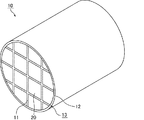
図1は、本発明の実施形態に係わるハニカム構造体の一例を模式的に示す斜視図であり、図2(a)は、本発明の実施形態に係わるハニカム構造体を構成するハニカム焼成体の一例を模式的に示す斜視図であり、図2(b)は、図2(a)に示すハニカム焼成体のA−A線断面図である。
(First embodiment)
Hereinafter, a first embodiment which is an embodiment of a honeycomb structure of the present invention will be described with reference to the drawings.
FIG. 1 is a perspective view schematically showing an example of a honeycomb structure according to an embodiment of the present invention, and FIG. 2A is a view of a honeycomb fired body constituting the honeycomb structure according to the embodiment of the present invention. FIG. 2B is a perspective view schematically showing an example, and FIG. 2B is a cross-sectional view taken along line AA of the honeycomb fired body shown in FIG.
図1に示すハニカム構造体10は、多孔質の炭化ケイ素ハニカム焼成体からなり、図2(a)及び図2(b)に示すような形状のハニカム焼成体20が接着材層11を介して複数個結束されてセラミックブロック13を構成し、セラミックブロック13の外周に外周コート層12が形成されている。
A
図2(a)及び図2(b)に示すハニカム焼成体20には、多数のセル21がセル壁23を隔てて長手方向(図2(a)中、矢印aの方向)に並設されており、セル21のいずれかの端部が封止材22によって封止されている。従って、一方の端面25で開口したセル21に流入した排ガスGは、必ずセル21を隔てるセル壁23を通過した後、他方の端面26で開口した他のセル21から流出するようになっている。このようにして、セル壁23がPM等を捕集するためのフィルタとして機能する。
なお、ハニカム焼成体及びハニカム構造体の表面のうち、セルが開口している面を端面といい、端面以外の面を側面という。
In the honeycomb fired
Of the surfaces of the honeycomb fired body and the honeycomb structure, a surface in which cells are open is referred to as an end surface, and a surface other than the end surface is referred to as a side surface.
図3は、本発明の実施形態に係わるハニカム焼成体を構成する炭化ケイ素粒子同士の結合状態を模式的に示す説明図である。
図3に示すように、ハニカム焼成体を構成する炭化ケイ素粒子31は、互いにネック31aを介して結合されており、その表面には、厚さが5〜100nmのケイ素を含む酸化物層32(シリカ膜)が形成されている。
FIG. 3 is an explanatory view schematically showing a bonded state of silicon carbide particles constituting the honeycomb fired body according to the embodiment of the present invention.
As shown in FIG. 3, the
ハニカム焼成体を構成する炭化ケイ素粒子の表面に形成された酸化物層の厚さについては、X線光電子分光法(XPS)を用いて測定することができる。X線光電子分光法は、サンプル表面にX線を照射し、生じる光電子のエネルギーをエネルギーアナライザーとよばれる装置で測定する分析法である。X線光電子分光法(XPS)により、サンプルの構成元素とその電子状態を分析することができる。また、X線光電子分析とイオンスパッタリングを交互に繰り返すことにより、試料の深さ方向の組成の変化を知ることができる。 The thickness of the oxide layer formed on the surface of the silicon carbide particles constituting the honeycomb fired body can be measured using X-ray photoelectron spectroscopy (XPS). X-ray photoelectron spectroscopy is an analysis method in which the surface of a sample is irradiated with X-rays and the energy of the generated photoelectrons is measured with an apparatus called an energy analyzer. The constituent elements of the sample and their electronic states can be analyzed by X-ray photoelectron spectroscopy (XPS). Further, by alternately repeating X-ray photoelectron analysis and ion sputtering, it is possible to know a change in the composition in the depth direction of the sample.
本発明の実施形態に係わるハニカム構造体においては、イオンスパッタリングにより一定速度で表面を削り取りながら、X線光電子分光法(XPS)によりその組成を分析することにより、酸化物層の深さ(厚み)を求めることができる。このような測定方法を用いた測定結果に基づき、上記炭化ケイ素の表面には、厚さが5〜100nmのケイ素を含む酸化物層32(シリカ膜)が形成されているとしている。 In the honeycomb structure according to the embodiment of the present invention, the depth (thickness) of the oxide layer is obtained by analyzing the composition by X-ray photoelectron spectroscopy (XPS) while scraping the surface at a constant speed by ion sputtering. Can be requested. Based on the measurement result using such a measurement method, an oxide layer 32 (silica film) containing silicon having a thickness of 5 to 100 nm is formed on the surface of the silicon carbide.
ハニカム焼成体の製造方法については、後で詳しく説明するが、炭化ケイ素粒子31がネック31a等を介して結合したハニカム焼成体は、脱脂工程、焼成工程を経て製造される。原料粒子の炭化ケイ素粒子の表面には、殆ど酸化物層は形成されていない。
The method for manufacturing the honeycomb fired body will be described in detail later. The honeycomb fired body in which the
すなわち、従来のハニカム構造体の製造方法においては、上記脱脂処理、焼成処理により得られた炭化ケイ素焼成体では、炭化ケイ素粒子の表面には、5nm未満の厚さの酸化物層しか形成されていないと考えられる。一方、特許文献1に記載の従来のハニカム構造体のように、意識的に炭化ケイ素粒子の表面に酸化物層を形成した場合には、例えば、100nmを超えるような比較的厚い酸化物層が形成されていると考えられる。それに対して本発明の実施形態のハニカム構造体では、炭化ケイ素粒子の表面に5〜100nmと従来と異なる厚さの酸化物層が形成されている。
酸化物層の厚さの下限は、5nmが好ましく、20nmがより好ましく、35nmがさらに好ましい。酸化物層の厚さの上限は、100nmが好ましく、90nmがより好ましく、70nmがさらに好ましい。
酸化物層は、8.0〜94.8nmがより好ましい。また、重量増加率は、0.06〜0.49重量%が好ましい。酸化物層の厚さを一定の値となるように制御することができるからである。
That is, in the conventional method for manufacturing a honeycomb structure, in the silicon carbide fired body obtained by the above degreasing treatment and firing treatment, only an oxide layer having a thickness of less than 5 nm is formed on the surface of the silicon carbide particles. It is not considered. On the other hand, when the oxide layer is intentionally formed on the surface of the silicon carbide particles as in the conventional honeycomb structure described in Patent Document 1, for example, a relatively thick oxide layer exceeding 100 nm is formed. It is thought that it is formed. On the other hand, in the honeycomb structure according to the embodiment of the present invention, an oxide layer having a thickness different from the conventional thickness of 5 to 100 nm is formed on the surface of the silicon carbide particles.
The lower limit of the thickness of the oxide layer is preferably 5 nm, more preferably 20 nm, and even more preferably 35 nm. The upper limit of the thickness of the oxide layer is preferably 100 nm, more preferably 90 nm, and even more preferably 70 nm.
As for an oxide layer, 8.0-94.8 nm is more preferable. The weight increase rate is preferably 0.06 to 0.49% by weight. This is because the thickness of the oxide layer can be controlled to be a constant value.
本発明の実施の形態に係わるハニカム構造体において、ハニカム焼成体の一方の端面近傍の酸化物層の厚さから他方の端面近傍の酸化物層の厚さを引いた値が、一方の端面近傍又は他方の端面近傍の酸化物層の厚さを基準としてその0.5〜2倍であることが好ましい。ハニカム焼成体の一方の端面近傍と他方の端面近傍の酸化物層の厚さの差を、0.5〜2倍に抑えることにより、フィルタや触媒担体として使用した際、再生時等に発生する熱膨張差に起因する応力がより小さくなり、ハニカム焼成体にクラックがより入りにくくなる。
ハニカム焼成体の一方の端面近傍と他方の端面近傍の酸化物層の厚さの差は、0.5〜1.5倍が好ましく、より1.0に近いのがさらに好ましい。
In the honeycomb structure according to the embodiment of the present invention, the value obtained by subtracting the thickness of the oxide layer in the vicinity of the other end face from the thickness of the oxide layer in the vicinity of one end face of the honeycomb fired body is in the vicinity of the one end face. Or it is preferable that it is 0.5 to 2 times the thickness of the oxide layer near the other end face. When used as a filter or a catalyst carrier, the difference in thickness between the oxide layer near one end face and the other end face of the honeycomb fired body is suppressed to 0.5 to 2 times. The stress due to the difference in thermal expansion becomes smaller, and cracks are less likely to enter the honeycomb fired body.
The difference in the thickness of the oxide layer near one end face and the other end face of the honeycomb fired body is preferably 0.5 to 1.5 times, and more preferably closer to 1.0.
本発明の実施の形態に係わるハニカム構造体を構成するハニカム焼成体の気孔率は、30〜70%であることが望ましい。
ハニカム焼成体の気孔率が30〜70%であると、ハニカム焼成体の強度を維持することが可能であるとともに、排ガスがセル壁を通過する際の抵抗を低く保つことができるからである。
The porosity of the honeycomb fired body constituting the honeycomb structure according to the embodiment of the present invention is preferably 30 to 70%.
This is because when the porosity of the honeycomb fired body is 30 to 70%, the strength of the honeycomb fired body can be maintained and the resistance when the exhaust gas passes through the cell walls can be kept low.
これに対し、上記ハニカム焼成体の気孔率が30%未満であると、排ガスがセル壁を通過しにくくなり、早期に目詰まりを起こし易くなる。一方、上記ハニカム焼成体の気孔率が70%を超えると、ハニカム焼成体の強度が低下して容易に破壊され易くなる。 On the other hand, when the porosity of the honeycomb fired body is less than 30%, the exhaust gas hardly passes through the cell walls, and clogging is likely to occur at an early stage. On the other hand, when the porosity of the honeycomb fired body is more than 70%, the strength of the honeycomb fired body is lowered and easily broken.
ハニカム焼成体の平均気孔径は5〜30μmであることが望ましい。
ハニカム焼成体で構成されるハニカム構造体をフィルタとして使用した場合、ハニカム焼成体の平均気孔径が5μm未満であると、ハニカム構造体の圧力損失が高くなる。一方、ハニカム焼成体の平均気孔径が30μmを超えると、ハニカム構造体のPMの捕集効率が低くなる。
上記気孔率及び平均気孔径は、例えば、水銀圧入法により測定することができる。
The average pore diameter of the honeycomb fired body is desirably 5 to 30 μm.
When a honeycomb structure composed of a honeycomb fired body is used as a filter, if the average pore diameter of the honeycomb fired body is less than 5 μm, the pressure loss of the honeycomb structure increases. On the other hand, when the average pore diameter of the honeycomb fired body exceeds 30 μm, the PM collection efficiency of the honeycomb structure is lowered.
The porosity and average pore diameter can be measured, for example, by a mercury intrusion method.
上記ハニカム焼成体のセル壁の厚さは、特に限定されないが、0.12〜0.40mmが望ましい。
ハニカム焼成体のセル壁の厚さが0.12mm未満であると、ハニカム焼成体のハニカム構造を支持するセル壁の厚さが薄くなり、ハニカム焼成体の強度を保つことができなくなり、一方、上記セル壁の厚さが0.40mmを超えると、ハニカム構造体の圧力損失の上昇を引き起こし易くなるからである。
The thickness of the cell wall of the honeycomb fired body is not particularly limited, but is preferably 0.12 to 0.40 mm.
When the thickness of the cell wall of the honeycomb fired body is less than 0.12 mm, the thickness of the cell wall supporting the honeycomb structure of the honeycomb fired body becomes thin, and the strength of the honeycomb fired body cannot be maintained. This is because if the thickness of the cell wall exceeds 0.40 mm, the pressure loss of the honeycomb structure tends to increase.
また、上記ハニカム焼成体の長手方向に垂直な断面におけるセル密度は特に限定されないが、望ましい下限は、31.0個/cm2(200個/in2)、望ましい上限は、93.0個/cm2(600個/in2)、より望ましい下限は、38.8個/cm2(250個/in2)、より望ましい上限は、77.5個/cm2(500個/in2)である。 The cell density in the cross section perpendicular to the longitudinal direction of the honeycomb fired body is not particularly limited, but the desirable lower limit is 31.0 / cm 2 (200 / in 2 ), and the desirable upper limit is 93.0 / cm 2 (600 / in 2 ), the more desirable lower limit is 38.8 / cm 2 (250 / in 2 ), and the more desirable upper limit is 77.5 / cm 2 (500 / in 2 ). is there.
次に、本発明の実施形態に係わるハニカム構造体の製造方法について説明する。
まず、セラミック粉末とバインダーとを含む原料ペーストを押出成形することによってハニカム成形体を作製する成形工程を行う。
Next, a method for manufacturing a honeycomb structure according to an embodiment of the present invention will be described.
First, a forming process for producing a honeycomb formed body is performed by extruding a raw material paste containing ceramic powder and a binder.
この場合、例えば、セラミック原料として平均粒子径の異なる炭化ケイ素粉末、有機バインダー、液状の可塑剤、潤滑剤及び水を混合することにより、ハニカム成形体製造用の原料ペーストを調製する。 In this case, for example, a raw material paste for manufacturing a honeycomb formed body is prepared by mixing silicon carbide powder having different average particle sizes, an organic binder, a liquid plasticizer, a lubricant, and water as ceramic raw materials.
続いて、上記原料ペーストを押出成形機に投入する。
上記原料ペーストを押出成形機に投入すると、原料ペーストは押出成形により所定の連続した形状のハニカム成形体となる。次いで、押出成形された連続するハニカム成形体を所定の長さに切断する。
Subsequently, the raw material paste is put into an extrusion molding machine.
When the raw material paste is put into an extruder, the raw material paste becomes a honeycomb formed body having a predetermined continuous shape by extrusion. Next, the extruded continuous honeycomb formed body is cut into a predetermined length.
次いで、ハニカム成形体をマイクロ波乾燥機、熱風乾燥機、誘電乾燥機、減圧乾燥機、真空乾燥機、凍結乾燥機等を用いて乾燥させる。 Next, the honeycomb formed body is dried using a microwave dryer, a hot air dryer, a dielectric dryer, a vacuum dryer, a vacuum dryer, a freeze dryer or the like.
次に、ハニカム成形体の所定のセルに封止材となる封止材ペーストを充填して上記セルを目封じする封止工程を行う。封止材ペーストとしては、上記原料ペーストを用いることができる。
なお、切断工程、乾燥工程、封止工程の条件は、従来からハニカム焼成体を作製する際に用いられている条件を適用することができる。
Next, a sealing process is performed in which predetermined cells of the honeycomb formed body are filled with a sealing material paste serving as a sealing material to plug the cells. The raw material paste can be used as the sealing material paste.
In addition, the conditions conventionally used when manufacturing a honeycomb fired body can be applied to the conditions of the cutting process, the drying process, and the sealing process.
次に、ハニカム成形体中の有機物を脱脂炉中で加熱、分解する脱脂工程を行う。
この脱脂工程では、ハニカム成形体を酸素含有雰囲気下、300〜650℃に加熱する。
この後、脱脂処理が施されたハニカム成形体を焼成炉に搬送し、非酸化性雰囲気の下、2000〜2200℃に加熱することによりハニカム成形体中の炭化ケイ素粒子を焼結させる焼成工程を行ってハニカム焼成体を作製する。以上の工程によって、炭化ケイ素焼結体からなるハニカム焼成体を作製することができる。
Next, a degreasing step is performed in which the organic matter in the honeycomb formed body is heated and decomposed in a degreasing furnace.
In this degreasing step, the honeycomb formed body is heated to 300 to 650 ° C. in an oxygen-containing atmosphere.
Thereafter, the honeycomb formed body that has been subjected to the degreasing treatment is transported to a firing furnace, and heated to 2000 to 2200 ° C. in a non-oxidizing atmosphere to thereby sinter the silicon carbide particles in the honeycomb formed body. To produce a honeycomb fired body. Through the above steps, a honeycomb fired body made of a silicon carbide sintered body can be produced.
そして、得られたハニカム焼成体の側面に、接着材層用ペーストを塗布して接着材層用ペースト層を形成し、この接着材層用ペースト層を介して順次他のハニカム焼成体を積層する。この手順を繰り返して所定数のハニカム焼成体が接着材層用ペーストにより接着されたハニカム焼成体の集合体を作製する。なお、接着材層用ペーストとしては、例えば、無機バインダーと有機バインダーと無機繊維及び/又は無機粒子とからなるものを使用することができる。 Then, an adhesive layer paste is applied to the side surface of the obtained honeycomb fired body to form an adhesive layer paste layer, and other honeycomb fired bodies are sequentially stacked through the adhesive layer paste layer. . This procedure is repeated to produce an aggregate of honeycomb fired bodies in which a predetermined number of honeycomb fired bodies are bonded with the adhesive layer paste. In addition, as an adhesive material layer paste, what consists of an inorganic binder, an organic binder, an inorganic fiber, and / or an inorganic particle can be used, for example.
このハニカム焼成体の集合体を加熱して接着材層用ペースト層を乾燥、固化させて接着材層とすることにより、セラミック集合体を作製するセラミック集合体作製工程を行う。さらに、セラミック集合体の側面をダイヤモンドカッター等を用いて切削加工して円柱状のセラミックブロックを作製する外周加工工程を行う。 The honeycomb fired body aggregate is heated to dry and solidify the adhesive layer paste layer to form an adhesive layer, thereby performing a ceramic aggregate production process for producing a ceramic aggregate. Furthermore, the outer periphery processing process which cuts the side surface of a ceramic assembly using a diamond cutter etc. and produces a cylindrical ceramic block is performed.
なお、ハニカム成形体を作製する際、組み合わせると所定の形状(例えば、円柱形状等)となり、外周加工を必要としない種々の形状のハニカム成形体を作製し、それを焼成することにより、種々の形状のハニカム焼成体を作製し、この後、それらのハニカム焼成体を接着材層用ペーストを介して組み合わせることにより、セラミックブロックを作製する方法をとることもできる。この場合には、外周加工工程が必要でなくなる。また、この場合には、以下に記載する外周コート層形成工程も、必ずしも必要でない。 When manufacturing a honeycomb formed body, when combined, it becomes a predetermined shape (for example, a columnar shape, etc.), and various shapes are formed by firing honeycomb formed bodies having various shapes that do not require peripheral processing, A method of producing a ceramic block can be taken by producing a honeycomb fired body having a shape and then combining the honeycomb fired bodies with an adhesive layer paste. In this case, the outer periphery processing step is not necessary. In this case, the outer peripheral coat layer forming step described below is not necessarily required.
次いで、円柱状としたセラミックブロックの外周に、外周コート層用ペーストを塗布し、乾燥、固化して外周コート層を形成する外周コート層形成工程を行う。
なお、上記外周コート層用ペーストを構成する材料としては、上記接着材層用ペーストと同様の材料を用いることができる。上記外周コート層用ペーストは、接着材ペースト層用ペーストと異なる材料を用いてもよい。
Next, an outer peripheral coat layer forming step is performed in which the outer peripheral coat layer paste is applied to the outer periphery of the cylindrical ceramic block, dried and solidified to form the outer peripheral coat layer.
In addition, as a material which comprises the said outer periphery coating layer paste, the material similar to the said adhesive material layer paste can be used. The outer peripheral coat layer paste may be made of a material different from the adhesive paste layer paste.
本発明の実施形態に係わるハニカム構造体の製造方法においては、焼成工程の後、セラミック集合体作製工程の後、外周加工工程の後、又は、外周コート層形成工程の後のいずれかにおいて、酸化性雰囲気の下、700〜1100℃で加熱処理する加熱処理工程を行って、ハニカム焼成体を構成する炭化ケイ素粒子の表面に5〜100nmの厚さの酸化物層を形成する。 In the method for manufacturing a honeycomb structure according to the embodiment of the present invention, the oxidation is performed after the firing step, after the ceramic aggregate manufacturing step, after the outer peripheral processing step, or after the outer peripheral coat layer forming step. Then, a heat treatment step of heat treatment at 700 to 1100 ° C. is performed in a neutral atmosphere to form an oxide layer having a thickness of 5 to 100 nm on the surface of the silicon carbide particles constituting the honeycomb fired body.
上記炭化ケイ素粒子の表面に酸化物層を形成する加熱処理条件に関し、700℃で加熱処理する際には、3時間以上加熱処理を行う方が好ましい。加熱処理温度が上昇するに従って、加熱処理時間は短くてもよく、例えば、1000℃では、少なくとも1時間、1100℃では少なくとも30分間加熱処理を行うことが好ましい。加熱処理時間が足りないと、酸化物層の厚さが5nm未満となる。なお、1100℃で加熱する場合には、4時間以下とすることがよい。1100℃で加熱する場合4時間を超えると、酸化物層の厚さが100nmを超えることとなる。しかし、上記条件で加熱することにより5〜100nmの厚さの酸化物層を形成することができる。 Regarding the heat treatment conditions for forming the oxide layer on the surface of the silicon carbide particles, when heat treatment is performed at 700 ° C., it is preferable to perform the heat treatment for 3 hours or more. As the heat treatment temperature rises, the heat treatment time may be shorter. For example, the heat treatment is preferably performed at 1000 ° C. for at least 1 hour and at 1100 ° C. for at least 30 minutes. If the heat treatment time is insufficient, the thickness of the oxide layer is less than 5 nm. In addition, when heating at 1100 degreeC, it is good to set it as 4 hours or less. When heating at 1100 ° C. for more than 4 hours, the thickness of the oxide layer exceeds 100 nm. However, an oxide layer having a thickness of 5 to 100 nm can be formed by heating under the above conditions.
上述したように、本発明におけるケイ素を含む酸化物層の厚さとは、ハニカム構造体を車等に搭載して使用する前の酸化物層の厚さをいう。 As described above, the thickness of the oxide layer containing silicon in the present invention refers to the thickness of the oxide layer before the honeycomb structure is used in a car or the like.
また、上記炭化ケイ素粒子の表面に酸化物層を形成する加熱処理時の酸素濃度は、5〜21容量%が好ましい。酸素濃度が5容量%未満では、長時間の加熱が必要となり易く、コストが高くなり易くなる。また、酸素濃度が約5容量%未満では、炭化ケイ素の表面の酸化が不安定となり易く、所定の厚さの酸化物層を形成することが困難になる。一方、酸素濃度が21容量%を超えた場合には、加熱装置内に酸素を供給する必要があるためコストが高くなり易くなる。また、コスト面及び作業効率の面から考えると、空気を用いて酸化物層を形成するのが好ましい。 The oxygen concentration during the heat treatment for forming the oxide layer on the surface of the silicon carbide particles is preferably 5 to 21% by volume. If the oxygen concentration is less than 5% by volume, heating for a long time is likely to be required, and the cost tends to increase. On the other hand, when the oxygen concentration is less than about 5% by volume, the oxidation of the surface of silicon carbide tends to be unstable, and it becomes difficult to form an oxide layer having a predetermined thickness. On the other hand, when the oxygen concentration exceeds 21% by volume, it is necessary to supply oxygen into the heating device, which tends to increase the cost. In view of cost and work efficiency, it is preferable to form the oxide layer using air.
上述したハニカム構造体に外周加工工程が必要ない場合には、セラミック集合体作製工程の後、加熱処理工程を行って酸化物層を形成してもよい。 When the above-described honeycomb structure does not require an outer periphery processing step, an oxide layer may be formed by performing a heat treatment step after the ceramic aggregate manufacturing step.
以上の工程によって、5〜100nmの厚さの酸化物層を有するハニカム焼成体が接着材層を介して複数個接着されてなるセラミックブロックの外周部に外周コート層が設けられた円柱形状のハニカム構造体を製造することができる。 A cylindrical honeycomb in which an outer peripheral coat layer is provided on the outer periphery of a ceramic block in which a plurality of honeycomb fired bodies having an oxide layer having a thickness of 5 to 100 nm are bonded through an adhesive layer by the above-described steps. A structure can be manufactured.
本発明の実施形態に係わるハニカム構造体の製造方法における接着工程は、接着材層用ペーストを各ハニカム焼成体の側面に塗布する方法以外に、例えば、作製するセラミックブロック(又はハニカム焼成体の集合体)の形状と同形状の型枠内に各ハニカム焼成体を仮固定した状態とし、接着材層用ペーストを各ハニカム焼成体間に注入する方法等によって行ってもよい。 The bonding step in the method for manufacturing a honeycomb structure according to the embodiment of the present invention includes, for example, a ceramic block (or a set of honeycomb fired bodies to be manufactured) other than the method of applying the adhesive layer paste to the side surface of each honeycomb fired body. The honeycomb fired bodies may be temporarily fixed in a mold having the same shape as the shape of the body, and the adhesive layer paste may be injected between the honeycomb fired bodies.
以下、本実施形態のハニカム構造体の作用効果について列挙する。
(1)本実施形態のハニカム構造体では、ハニカム焼成体を構成する炭化ケイ素粒子の表面には、厚さが5〜100nmの厚さのケイ素を含む酸化物層が形成されているので、ハニカム焼成体の骨材(酸化物層の除くハニカム焼成体)の厚さに対するハニカム焼成体を構成する粒子の表面に形成された酸化物の厚さの比を小さく保つことができる。従って、ハニカム焼成体に堆積したススを燃焼させた時に、ハニカム焼成体の骨材(酸化物層の除くハニカム焼成体)である炭化ケイ素とその表面に成形された酸化物層との熱膨張率の差に起因する応力が大きくならず、ハニカム構造体にクラックが発生しにくい。
Hereinafter, effects of the honeycomb structure of the present embodiment will be listed.
(1) In the honeycomb structure of the present embodiment, since the oxide layer containing silicon having a thickness of 5 to 100 nm is formed on the surface of the silicon carbide particles constituting the honeycomb fired body, The ratio of the thickness of the oxide formed on the surface of the particles constituting the honeycomb fired body to the thickness of the aggregate of the fired body (honeycomb fired body excluding the oxide layer) can be kept small. Therefore, when the soot deposited on the honeycomb fired body is burned, the thermal expansion coefficient between the silicon carbide as the aggregate of the honeycomb fired body (the honeycomb fired body excluding the oxide layer) and the oxide layer formed on the surface thereof The stress resulting from the difference between the two is not increased, and cracks are hardly generated in the honeycomb structure.
(2)本実施形態のハニカム構造体では、5〜100nmの厚さの酸化物層が形成されている。このように充分な厚さの酸化物層が形成されているため、ハニカム構造体が1500℃以上の高温に晒された場合であっても、ハニカム構造体を構成するハニカム焼成体の内部に存在する炭化ケイ素が酸化されにくいので、酸化物層の厚さが厚くなりにくく、安定した特性を有するハニカム焼成体となる。 (2) In the honeycomb structure of the present embodiment, an oxide layer having a thickness of 5 to 100 nm is formed. Since the oxide layer having a sufficient thickness is formed in this manner, even when the honeycomb structure is exposed to a high temperature of 1500 ° C. or more, it exists inside the honeycomb fired body constituting the honeycomb structure. Since the silicon carbide to be oxidized is difficult to oxidize, the thickness of the oxide layer is difficult to increase, and a honeycomb fired body having stable characteristics is obtained.
以下、本発明の第一実施形態のハニカム構造体をより具体的に開示した実施例を示すが、本発明はこれら実施例のみに限定されるものではない。 Hereinafter, examples more specifically disclosing the honeycomb structure of the first embodiment of the present invention will be shown, but the present invention is not limited to these examples.
(実施例1)
平均粒子径22μmを有する炭化ケイ素の粗粉末52.8重量%と、平均粒子径0.5μmの炭化ケイ素の微粉末22.6重量%とを混合し、得られた混合物に対して、アクリル樹脂2.1重量%、有機バインダー(メチルセルロース)4.6重量%、潤滑剤(日本油脂社製 ユニルーブ)2.8重量%、グリセリン1.3重量%、及び、水13.8重量%を加えて混練して原料ペーストを得た。得られた原料ペーストを用いて、押出成形及び押出成形体の切断を行い、図2(a)及び図2(b)に示した断面形状と同様の断面形状であってセルの封止がされていない生のハニカム成形体を作製した。マイクロ波乾燥機を用いてこのハニカム成形体を乾燥した。
Example 1
A mixture of 52.8% by weight of silicon carbide coarse powder having an average particle diameter of 22 μm and 22.6% by weight of fine powder of silicon carbide having an average particle diameter of 0.5 μm is obtained. 2.1% by weight, 4.6% by weight of organic binder (methyl cellulose), 2.8% by weight of lubricant (Unilube manufactured by NOF Corporation), 1.3% by weight of glycerin, and 13.8% by weight of water The raw material paste was obtained by kneading. Using the obtained raw material paste, extrusion molding and cutting of the extrusion-molded body were performed, and the cells were sealed with the same cross-sectional shape as shown in FIGS. 2 (a) and 2 (b). A raw honeycomb formed body was prepared. The honeycomb formed body was dried using a microwave dryer.
次に、乾燥後のハニカム成形体の所定のセルに封止材ペーストとして上記原料ペーストを充填してセルの封止を行い、再び乾燥機を用いて乾燥させた。 Next, predetermined cells of the dried honeycomb formed body were filled with the raw material paste as a sealing material paste to seal the cells, and again dried using a dryer.
乾燥したハニカム成形体を400℃で脱脂し、常圧のアルゴン雰囲気下2200℃、3時間の条件で焼成を行うことにより、炭化ケイ素焼結体からなるハニカム焼成体を作製した。ハニカム焼成体の気孔率は45%、平均気孔径が15μm、高さ34.3mm×幅34.3mm×長さ150mm、セルの数(セル密度)が46.5個/cm2、セル壁の厚さが0.25mm(10mil)であった。
そして、得られたハニカム焼成体に対し、空気雰囲気中、700℃で3時間加熱処理を行った。
The dried honeycomb formed body was degreased at 400 ° C. and fired under a normal pressure argon atmosphere at 2200 ° C. for 3 hours to prepare a honeycomb fired body made of a silicon carbide sintered body. The honeycomb fired body has a porosity of 45%, an average pore diameter of 15 μm, a height of 34.3 mm × a width of 34.3 mm × a length of 150 mm, a number of cells (cell density) of 46.5 cells / cm 2 , The thickness was 0.25 mm (10 mil).
Then, the obtained honeycomb fired body was subjected to heat treatment at 700 ° C. for 3 hours in an air atmosphere.
平均繊維長20μm、平均繊維径2μmのアルミナファイバ30重量%、平均粒子径0.6μmの炭化ケイ素粒子21重量%、シリカゾル(固形分30重量%)15重量%、カルボキシメチルセルロース5.6重量%、及び、水28.4重量%を含む耐熱性の接着材層用ペーストを用いて、ハニカム焼成体を多数接着させ、ハニカム焼成体の集合体を作製した。 An average fiber length of 20 μm, an alumina fiber having an average fiber diameter of 2 μm, 30% by weight, silicon carbide particles having an average particle diameter of 0.6 μm, 21% by weight, silica sol (solid content of 30% by weight), 15% by weight, carboxymethylcellulose, 5.6% by weight, A large number of honeycomb fired bodies were bonded using a heat-resistant paste for adhesive layer containing 28.4% by weight of water to produce an aggregate of honeycomb fired bodies.
さらに、このハニカム焼成体の集合体を120℃で乾燥させてセラミック集合体とした後、続いて、ダイヤモンドカッターを用いて切断することにより、円柱状のセラミックブロックを作製した。 Furthermore, the aggregate of the honeycomb fired bodies was dried at 120 ° C. to form a ceramic aggregate, and then cut using a diamond cutter to produce a cylindrical ceramic block.
次に、外周コート層用ペーストとして、上記接着材層用ペーストを用いて、セラミックブロックの外周部に厚さ0.2mmの外周コート層用ペースト層を形成した。そして、この外周コート層用ペースト層を120℃で乾燥して外周コート層を形成し、外周に外周コート層が形成された直径143.8mm×長さ150mmの円柱状のハニカム構造体を作製した。 Next, using the adhesive layer paste as an outer coat layer paste, an outer coat layer paste layer having a thickness of 0.2 mm was formed on the outer periphery of the ceramic block. Then, this outer peripheral coat layer paste layer was dried at 120 ° C. to form an outer peripheral coat layer, and a cylindrical honeycomb structure having a diameter of 143.8 mm and a length of 150 mm was formed. .
(実施例2〜6)
ハニカム焼成体に、表1に示した温度、時間で加熱処理を行ったほかは、実施例1と同様にしてハニカム構造体を作製した。実施例2〜6の処理条件は、それぞれ、900℃10時間、1000℃3時間、1100℃1時間、1100℃3時間、1100℃4時間である。
(Examples 2 to 6)
A honeycomb structure was manufactured in the same manner as in Example 1 except that the honeycomb fired body was heat-treated at the temperature and time shown in Table 1. The processing conditions of Examples 2 to 6 are 900 ° C. for 10 hours, 1000 ° C. for 3 hours, 1100 ° C. for 1 hour, 1100 ° C. for 3 hours, and 1100 ° C. for 4 hours, respectively.
(比較例1)
比較例1では、ハニカム焼成体を作製した後、加熱処理は行わず、そのほかは、実施例1と同様にしてハニカム構造体を作製した。
(Comparative Example 1)
In Comparative Example 1, a honeycomb structure was manufactured in the same manner as in Example 1 except that no heat treatment was performed after the honeycomb fired body was manufactured.
(比較例2)
外周コート層を形成した後、表1に示した温度、時間(1100℃、5時間)で加熱処理を行ったほかは、実施例1と同様にしてハニカム構造体を作製した。
(Comparative Example 2)
After forming the outer peripheral coat layer, a honeycomb structure was manufactured in the same manner as in Example 1 except that heat treatment was performed at the temperature and time (1100 ° C., 5 hours) shown in Table 1.
(評価方法)
(1)X線光電子分光法(XPS)による酸化物層の厚さの測定
実施例1〜6及び比較例1〜2で作製した加熱処理工程を行ったハニカム焼成体(比較例1は、加熱処理なし)の1つについて、ダイヤモンドカッターを用いて20mm×20mm×0.25mmの板状のXPS測定用サンプルを作製した。そして、XPS測定用サンプルを用いてX線光電子分光法(XPS)により、酸化物層の厚さを測定した。
(Evaluation methods)
(1) Measurement of oxide layer thickness by X-ray photoelectron spectroscopy (XPS) Honeycomb fired bodies subjected to the heat treatment steps prepared in Examples 1 to 6 and Comparative Examples 1 and 2 (Comparative Example 1 is heating With respect to one of (no treatment), a plate-shaped XPS measurement sample of 20 mm × 20 mm × 0.25 mm was produced using a diamond cutter. And the thickness of the oxide layer was measured by the X ray photoelectron spectroscopy (XPS) using the sample for XPS measurement.
XPS装置としては、ULVAC−PHI社製のQuantera SXMを用い、X線源としては、モノクロ化されたAl−Kα線(Monochromated Al−Kα)を用いた。測定条件は、電圧:15kV、出力:25W、測定領域:100μmφとした。イオンスパッタ条件は、イオン種:Ar+、電圧:1kV(実施例1〜4及び比較例1)又は2kV(実施例5及び6並びに比較例2)、スパッタレート(SiO2換算):1.5nm/min(実施例1〜4及び比較例1)又は5.4nm/min(実施例5及び6並びに比較例2)とした。
上記XPS装置を用いて、実施例1〜6及び比較例1、2の各XPS測定用サンプルの定性分析(ワイドスキャン)、及び、C、O、Siについての深さ方向分析を行った。深さ方向分析の結果より、SiO2プロファイルの最高強度と最低強度の中間となる強度の時間と、各XPS測定用サンプルのスパッタレート(SiO2換算)から酸化物層の厚さを算出した。
X線光電子分光法(XPS)による実施例1〜6及び比較例1、2の酸化物層の厚さの測定の結果を表1に示す。実施例1〜6及び比較例1、2の酸化物層の厚さは、それぞれ、8.0nm、26.0nm、36.0nm、45.0nm、64.4nm、94.8nm、≦4nm、108.5nmであった。
A Quanta SXM manufactured by ULVAC-PHI was used as the XPS apparatus, and a monochromated Al-Kα ray (Monochromated Al-Kα) was used as the X-ray source. The measurement conditions were voltage: 15 kV, output: 25 W, measurement area: 100 μmφ. The ion sputtering conditions are as follows: ion species: Ar + , voltage: 1 kV (Examples 1 to 4 and Comparative Example 1) or 2 kV (Examples 5 and 6 and Comparative Example 2), sputtering rate (SiO 2 conversion): 1.5 nm / Min (Examples 1 to 4 and Comparative Example 1) or 5.4 nm / min (Examples 5 and 6 and Comparative Example 2).
Using the XPS apparatus, qualitative analysis (wide scan) of each XPS measurement sample of Examples 1 to 6 and Comparative Examples 1 and 2 and depth direction analysis of C, O, and Si were performed. From the result of depth direction analysis, the thickness of the oxide layer was calculated from the time of the strength that is intermediate between the highest strength and the lowest strength of the SiO 2 profile and the sputter rate (converted to SiO 2 ) of each XPS measurement sample.
Table 1 shows the results of measuring the thicknesses of the oxide layers of Examples 1 to 6 and Comparative Examples 1 and 2 by X-ray photoelectron spectroscopy (XPS). The thicknesses of the oxide layers of Examples 1 to 6 and Comparative Examples 1 and 2 were 8.0 nm, 26.0 nm, 36.0 nm, 45.0 nm, 64.4 nm, 94.8 nm, ≦ 4 nm, 108, respectively. 0.5 nm.
(2)ハニカム構造体熱衝撃試験
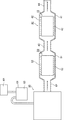
実施例1〜6及び比較例1、2でそれぞれ作製したハニカム構造体を用いて、触媒担体50及び排ガス浄化装置40が図4に示すような2Lのコモンレール式ディーゼルエンジン60の排気管62に接続された装置を組み上げた。そして、ハニカム構造体に堆積したPMの燃焼による熱衝撃試験を行った。そして、ハニカム構造体を構成する炭化ケイ素質ハニカム焼成体にクラックが発生したか否かを目視及び顕微鏡で観察した。
(2) Honeycomb structure thermal shock test Using the honeycomb structures produced in Examples 1 to 6 and Comparative Examples 1 and 2, respectively, the
具体的には、エンジンを回転数3000min−1、トルク50Nmで所定時間運転し、12g/LのPMをハニカム構造体に捕集させた。その後、エンジンを回転数4000min−1、フルロードにして、排ガスの温度を上昇させ、ハニカム構造体に堆積したPMを強制燃焼させ、ハニカム焼成体にクラックが発生したか否かを肉眼及び走査型電子顕微鏡(SEM)により観察した。実施例1〜6及び比較例1、2の各実施例において、ハニカム構造体の到達した最高温度は、いずれも1500℃を超えていた。また、実施例1〜6及び比較例1、2の実施例において、ディーゼルエンジンより排出された排ガスの水蒸気量は、2容量%であった。 Specifically, the engine was operated at a rotational speed of 3000 min −1 and a torque of 50 Nm for a predetermined time, and 12 g / L of PM was collected in the honeycomb structure. Thereafter, the engine is set to a rotational speed of 4000 min −1 , full load, the temperature of the exhaust gas is raised, PM deposited on the honeycomb structure is forcibly burned, and whether or not cracks are generated in the honeycomb fired body is visually and scanned. Observation was performed with an electron microscope (SEM). In each of Examples 1 to 6 and Comparative Examples 1 and 2, the maximum temperature reached by the honeycomb structure exceeded 1500 ° C. Moreover, in the Example of Examples 1-6 and Comparative Examples 1 and 2, the water vapor | steam amount of the waste gas discharged | emitted from the diesel engine was 2 volume%.
なお、ディーゼルエンジンの燃料中に触媒であるセリウム化合物が10ppm含まれるように、燃料にセリウム化合物を添加して、ハニカム構造体の熱衝撃試験(クラック評価)を行った。その結果を表1に示す。実施例1〜6は、クラックが発生しなかった。比較例1、2では、クラックが発生した。 In addition, the thermal shock test (crack evaluation) of the honeycomb structure was performed by adding a cerium compound to the fuel so that 10 ppm of cerium compound as a catalyst was contained in the fuel of the diesel engine. The results are shown in Table 1. In Examples 1 to 6, no crack occurred. In Comparative Examples 1 and 2, cracks occurred.
(3)重量増加率の測定
実施例1〜6及び比較例2で作製したハニカム焼成体について、実施例1〜6及び比較例2と同様の条件で加熱処理を行い、加熱処理前後の重量を測定することにより、重量増加率を求めた。ここで、重量増加率(%)は、下記の(1)式で表される。
重量増加率(%)=(加熱処理後のハニカム焼成体の重量−加熱処理前のハニカム焼成体の重量)×100/加熱処理前のハニカム焼成体の重量・・・(1)
その結果を表1に示す。実施例1〜6及び比較例1、2の重量増加率は、それぞれ、0.06wt%、0.20wt%、0.25wt%、0.30wt%、0.33wt%、0.49wt%、0wt%、0.56wt%であった。なお、ハニカム焼成体の加熱処理を行わなかった比較例1については、重量増加率は、0wt%とした。
(3) Measurement of rate of weight increase About the honeycomb fired bodies manufactured in Examples 1 to 6 and Comparative Example 2, heat treatment was performed under the same conditions as in Examples 1 to 6 and Comparative Example 2, and the weight before and after the heat treatment was determined. By measuring, the weight increase rate was obtained. Here, the weight increase rate (%) is expressed by the following equation (1).
Weight increase rate (%) = (Weight of honeycomb fired body after heat treatment−Weight of honeycomb fired body before heat treatment) × 100 / Weight of honeycomb fired body before heat treatment (1)
The results are shown in Table 1. The weight increase rates of Examples 1 to 6 and Comparative Examples 1 and 2 are 0.06 wt%, 0.20 wt%, 0.25 wt%, 0.30 wt%, 0.33 wt%, 0.49 wt%, and 0 wt%, respectively. %, 0.56 wt%. In addition, about the comparative example 1 which did not heat-process a honeycomb fired body, the weight increase rate was 0 wt%.
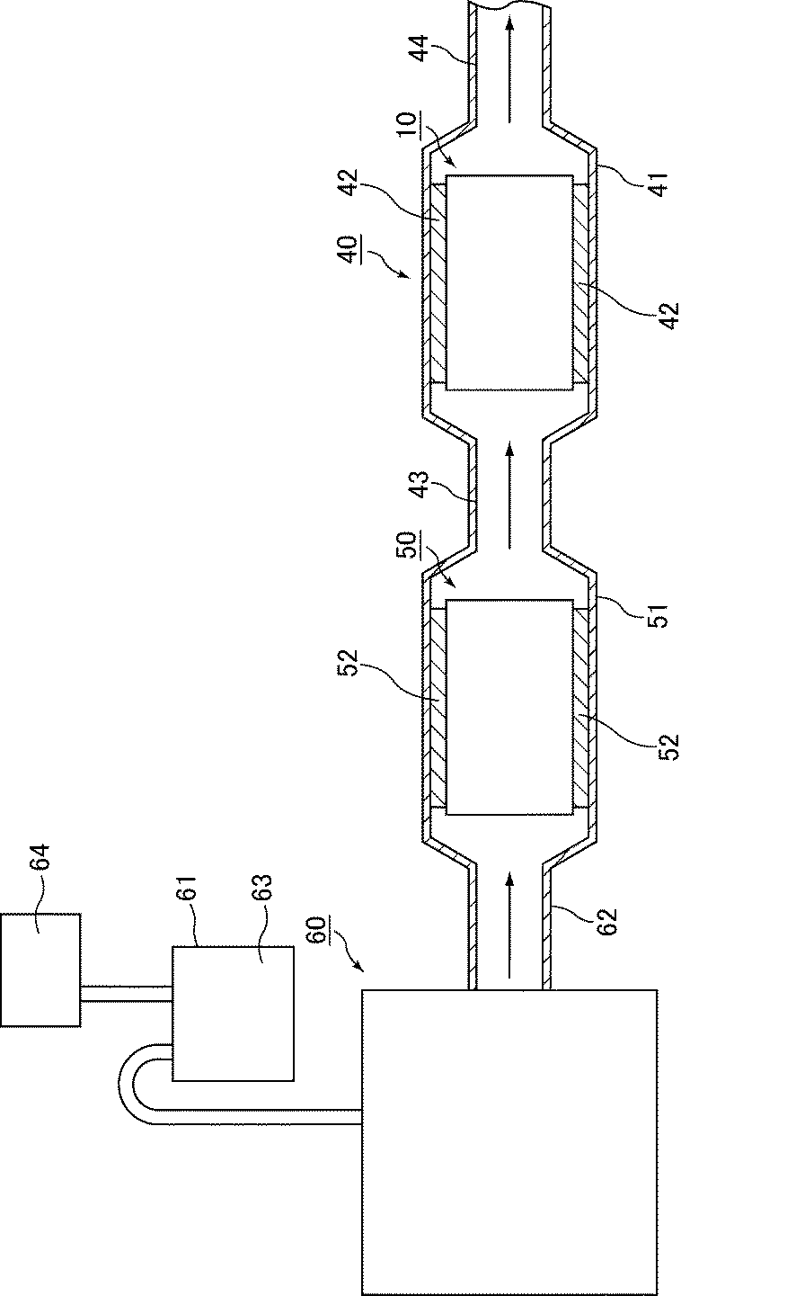
表1に示すように、厚さ8.0〜94.8nmの酸化物層が形成されたハニカム焼成体を用いてハニカム構造体を作製した実施例1〜6では、得られたハニカム構造体にPMを12g/L堆積させ、ハニカム構造体が1500℃を超える温度になるように燃焼させ、熱衝撃を与えた場合であっても、ハニカム構造体にクラックは観察されなかった。これに対し、比較例1のように加熱処理工程を行っていないもの(酸化物層の厚みを測定したところ、4nm以下であった)、及び、比較例2のようにハニカム構造体を構成するハニカム焼成体の酸化物層の厚さが108.5nmと100nmを超えたものでは、上記のような熱衝撃を与えることにより、ハニカム構造体にクラックが観察された。上記の結果から、酸化物層の厚さは、5〜100nmが好ましく、8.0〜94.8nmがより好ましいと考えられる。 As shown in Table 1, in Examples 1 to 6 in which a honeycomb structure was manufactured using a honeycomb fired body in which an oxide layer having a thickness of 8.0 to 94.8 nm was formed, Even when PM was deposited at 12 g / L, the honeycomb structure was burned to a temperature exceeding 1500 ° C., and thermal shock was applied, no cracks were observed in the honeycomb structure. On the other hand, the honeycomb structure is formed as in Comparative Example 1 where the heat treatment process was not performed (when the thickness of the oxide layer was measured, the thickness was 4 nm or less), and in Comparative Example 2. When the thickness of the oxide layer of the honeycomb fired body exceeded 108.5 nm and 100 nm, cracks were observed in the honeycomb structure by applying the thermal shock as described above. From the above results, it is considered that the thickness of the oxide layer is preferably 5 to 100 nm, and more preferably 8.0 to 94.8 nm.
(第二実施形態)
以下、本発明の一実施形態である第二実施形態に係わる排ガス浄化装置ついて図面を参照しつつ説明する。
(Second embodiment)
Hereinafter, an exhaust gas purification apparatus according to a second embodiment which is an embodiment of the present invention will be described with reference to the drawings.
図4は、本発明の実施形態に係わる排ガス浄化装置を模式的に示す説明図である。
図4に示すように、本実施形態に係わる排ガス浄化装置40は、排ガス入口43及び排ガス出口44を備えた金属容器41と、金属容器41内に保持シール材42を介して収容されたハニカム構造体10からなるハニカムフィルタとを備えている。ハニカムフィルタには、本発明の第一実施形態で説明したハニカム構造体10が用いられている。
FIG. 4 is an explanatory view schematically showing an exhaust gas purifying apparatus according to an embodiment of the present invention.
As shown in FIG. 4, the exhaust
また、排ガス浄化装置40より排気ガス入口側には、別の金属容器51内に保持シール材52を介して酸化触媒を担持した触媒担体50が収容されている。この触媒担体50が収容された金属容器51は、ディーゼルエンジン60の排気管62に接続されており、酸化触媒と排ガス浄化装置40とにより、ディーゼルエンジン60から排出された排気ガスの浄化を行う。
Further, on the exhaust gas inlet side from the exhaust
このディーゼルエンジン60は、図示していないが、コモンレール方式を採用しており、また、燃料容器61中の燃料63には、触媒64の添加が可能なように構成されている。
Although not shown, this
このような排ガス浄化装置40、触媒担体50及びディーゼルエンジン60を備えた車両においては、ハニカムフィルタに一定量のPMが堆積すると以下のような方法によりPMを除去する。
In a vehicle including such an exhaust
まず、燃料63にセリウム化合物等の触媒64を添加し、ディーゼルエンジン60から排出された排ガス中に触媒64が混合されるようにする。続いて、ポストインジェクションにより排ガスの温度を上昇させる。本実施形態では、排ガス浄化装置40よりエンジン側に酸化触媒を担持した触媒担体50が配置されているので、温度の上昇した排ガスは、触媒担体50の内部を通るが、これにより未燃焼の燃料が燃焼し、HC及びCOを除去しながら、排ガスの温度をさらに上昇させることができる。
First, a
また、排ガス中には、触媒64が混入されているため、PMの燃焼開始温度が低下し、ハニカムフィルタに堆積したPMが燃焼、除去される。
Further, since the
本実施形態で使用される保持シール材42、52は、ハニカム構造体10及び触媒担体50を金属容器41、51内で保持、固定するとともに、使用中のハニカム構造体10、触媒担体50を保温する断熱材として機能するマット状のものである。
The holding
以下、本実施形態の排ガス浄化装置の作用効果について列挙する。
(3)本実施形態の排ガス浄化装置は、燃料に触媒を添加してパティキュレートマターの燃焼開始温度を低下させて、ハニカムフィルタに堆積したパティキュレートマターを燃焼させて除去する方式の排ガス浄化装置として、好適に用いられる。その理由としては、以下の理由が考えられる。
すなわち、このような方法で堆積したPMを除去する方式の排ガス浄化装置に、本発明の実施形態のハニカム構造体を採用した場合には、ハニカム構造体にPMを大量に蓄積させることができる。その場合には、ハニカムフィルタ(ハニカム構造体)が1500℃以上の温度となることもある。しかしながら、このようなハニカムフィルタ(ハニカム構造体)の温度が1500℃を超えた場合であっても、ハニカム構造体を構成する炭化ケイ素の表面の酸化物層の厚さが5〜100nmに制御されているため、ハニカム焼成体の骨材(酸化物層の除くハニカム焼成体)である炭化ケイ素とその表面に成形された酸化物層との熱膨張率の差に起因する応力が大きくならず、ハニカム構造体にクラックが発生しにくい。
Hereafter, it enumerates about the effect of the exhaust gas purification apparatus of this embodiment.
(3) The exhaust gas purifying apparatus of the present embodiment is a type of exhaust gas purifying apparatus that adds a catalyst to the fuel to lower the combustion start temperature of the particulate matter and burns and removes the particulate matter deposited on the honeycomb filter. And is preferably used. The following reasons can be considered as the reason.
That is, when the honeycomb structure according to the embodiment of the present invention is employed in an exhaust gas purifying apparatus that removes PM accumulated by such a method, a large amount of PM can be accumulated in the honeycomb structure. In that case, the temperature of the honeycomb filter (honeycomb structure) may be 1500 ° C. or higher. However, even when the temperature of such a honeycomb filter (honeycomb structure) exceeds 1500 ° C., the thickness of the oxide layer on the surface of silicon carbide constituting the honeycomb structure is controlled to 5 to 100 nm. Therefore, the stress caused by the difference in thermal expansion coefficient between the silicon carbide which is the aggregate of the honeycomb fired body (honeycomb fired body excluding the oxide layer) and the oxide layer formed on the surface thereof is not increased, Cracks are unlikely to occur in the honeycomb structure.
(その他の実施形態)
本発明のハニカム構造体の断面の形状は、円形に限定されるものでなく、例えば、楕円形や、長円形、レーストラック形等であってもよい。
(Other embodiments)
The cross-sectional shape of the honeycomb structure of the present invention is not limited to a circular shape, and may be, for example, an elliptical shape, an oval shape, a race track shape, or the like.
本発明に係わるハニカム構造体は、炭化ケイ素粒子が金属ケイ素粒子により結合された状態のハニカム焼成体からなるものであってもよい。この場合、金属ケイ素の全体に対する含有割合は、40重量%以下であることが望ましい。本発明では、上記構成のハニカム焼成体の表面に酸化物層を形成するために、加熱処理を行うが、この加熱処理により金属ケイ素の表面にも酸化物層が形成される。そのため、金属ケイ素の溶融温度を超えるような温度に晒された場合においても、ハニカム焼成体の構造が崩れることはなく、上述した本願発明の効果を奏する。 The honeycomb structure according to the present invention may be a honeycomb fired body in which silicon carbide particles are bonded with metal silicon particles. In this case, it is desirable that the content ratio of the metal silicon is 40% by weight or less. In the present invention, a heat treatment is performed in order to form an oxide layer on the surface of the honeycomb fired body having the above-described configuration. By this heat treatment, an oxide layer is also formed on the surface of metal silicon. Therefore, even when exposed to a temperature exceeding the melting temperature of the metallic silicon, the structure of the honeycomb fired body is not destroyed, and the above-described effect of the present invention is achieved.
本発明の第一実施形態に係わるハニカム構造体は、炭化ケイ素ハニカム焼成体が接着材層を介して複数個結束されたセラミックブロックの外周に外周コート層が形成されているが、ハニカム構造体の構成は、上記構成に限定されない。 In the honeycomb structure according to the first embodiment of the present invention, an outer peripheral coat layer is formed on the outer periphery of a ceramic block in which a plurality of silicon carbide honeycomb fired bodies are bonded through an adhesive layer. The configuration is not limited to the above configuration.
本発明のハニカム構造体は、1個の前記炭化ケイ素質ハニカム焼成体からなるものであってよい。この場合にも、本発明の第一実施形態に係わるハニカム構造体と同様の効果を奏する。 The honeycomb structure of the present invention may be composed of one piece of the silicon carbide honeycomb fired body. Also in this case, the same effect as the honeycomb structure according to the first embodiment of the present invention is obtained.
本発明のハニカム構造体には、排ガスを浄化するための触媒(例えば、酸化物触媒)を担持させてもよい。 The honeycomb structure of the present invention may carry a catalyst (for example, an oxide catalyst) for purifying exhaust gas.
触媒を担持させる場合には、担持させる触媒としては、例えば、白金、パラジウム、ロジウム等の貴金属が望ましく、このなかでは、白金がより望ましい。また、その他の触媒として、例えば、カリウム、ナトリウム等のアルカリ金属、バリウム等のアルカリ土類金属を用いることもできる。 When a catalyst is supported, the catalyst to be supported is preferably a noble metal such as platinum, palladium, rhodium, etc. Among these, platinum is more preferable. Further, as other catalysts, for example, alkali metals such as potassium and sodium, and alkaline earth metals such as barium can be used.
さらに、CeO2、ZrO2、FeO2、Fe2O3、CuO、CuO2、Mn2O3、MnO等の金属酸化物、組成式AnB1−nCO3(式中、AはLa、Nd、Sm、Eu、Gd又はYであり、Bはアルカリ金属又はアルカリ土類金属であり、CはMn、Co、Fe又はNiであり、0≦n≦1である)で表される複合酸化物等からなる酸化物触媒を用いることもできる。
これらの触媒は、単独で用いてもよいし、2種以上併用してもよい。
Further, CeO 2, ZrO 2, FeO 2, Fe 2 O 3, CuO, CuO 2, Mn 2 O 3, metal oxides such as MnO, the composition formula A n B 1-n CO 3 ( wherein, A is La Nd, Sm, Eu, Gd or Y, B is an alkali metal or alkaline earth metal, C is Mn, Co, Fe or Ni, and 0 ≦ n ≦ 1) An oxide catalyst made of an oxide or the like can also be used.
These catalysts may be used alone or in combination of two or more.
また、触媒を担持させる場合には、触媒の高分散を目的として、ハニカム構造体のセル壁に触媒担持層を形成してもよい。上記触媒担持層を形成する材料としては、比表面積が高く触媒を高分散させて担持させることのできる材料であることが望ましく、例えば、アルミナ、チタニア、ジルコニア、シリカ等の酸化物セラミックが挙げられる。
これらの材料は、単独で使用してもよいし、2種以上併用してもよい。
Further, when the catalyst is supported, a catalyst support layer may be formed on the cell wall of the honeycomb structure for the purpose of highly dispersing the catalyst. The material for forming the catalyst supporting layer is preferably a material having a high specific surface area and capable of supporting the catalyst in a highly dispersed state, and examples thereof include oxide ceramics such as alumina, titania, zirconia, and silica. .
These materials may be used alone or in combination of two or more.
10 ハニカム構造体
11 接着材層
12 外周コート層
13 セラミックブロック
20 ハニカム焼成体
21 セル
22 封止材
23 セル壁
31 炭化ケイ素粒子
31a ネック
32 酸化物層
40 排ガス浄化装置
41、51 金属容器
42、52 保持シール材
43 排ガス入口
44 排ガス出口
50 触媒担体
60 ディーゼルエンジン
61 燃料容器
62 排気管
63 燃料
64 触媒
DESCRIPTION OF
Claims (10)
前記炭化ケイ素質ハニカム焼成体を構成する炭化ケイ素粒子の表面にはケイ素を含む酸化物層が形成されており、
X線光電子分光法(XPS)を用いて測定した前記酸化物層の厚さは、5〜100nmであることを特徴とするハニカム構造体。 A honeycomb structure including a porous silicon carbide honeycomb fired body in which a large number of cells are arranged side by side in the longitudinal direction across a cell wall,
An oxide layer containing silicon is formed on the surface of the silicon carbide particles constituting the silicon carbide honeycomb fired body,
A honeycomb structure, wherein the thickness of the oxide layer measured using X-ray photoelectron spectroscopy (XPS) is 5 to 100 nm.
ディーゼルエンジンより排出されたパティキュレートマターを濾過することにより排ガスを浄化する排ガス浄化装置に用いられ、
前記ハニカム構造体には、燃焼を助ける触媒が含まれたパティキュレートが蓄積され、堆積したパティキュレートマターを燃焼させて除去する方式の排ガス浄化装置に用いられる請求項1〜7のいずれかに記載のハニカム構造体。 The honeycomb structure is
Used in exhaust gas purification devices that purify exhaust gas by filtering particulate matter discharged from diesel engines,
8. The honeycomb structure is used in an exhaust gas purification apparatus of a type in which particulates containing a catalyst that assists combustion are accumulated, and the deposited particulate matter is burned and removed. Honeycomb structure.
前記金属容器内に収容されたハニカム構造体と、
前記金属容器及び前記ハニカム構造体との間に介在する保持シール材とを備えた排ガス浄化装置であって、
前記ハニカム構造体は、請求項1〜8のいずれかに記載のハニカム構造体であることを特徴とする排ガス浄化装置。 A metal container having an exhaust gas inlet and an exhaust gas outlet;
A honeycomb structure housed in the metal container;
An exhaust gas purifying apparatus comprising a holding sealing material interposed between the metal container and the honeycomb structure,
The exhaust gas purification apparatus, wherein the honeycomb structure is the honeycomb structure according to any one of claims 1 to 8.
Priority Applications (1)
| Application Number | Priority Date | Filing Date | Title |
|---|---|---|---|
| JP2011225193A JP2012102004A (en) | 2010-10-13 | 2011-10-12 | Honeycomb structured body and exhaust gas purifying apparatus |
Applications Claiming Priority (3)
| Application Number | Priority Date | Filing Date | Title |
|---|---|---|---|
| JP2010230193 | 2010-10-13 | ||
| JP2010230193 | 2010-10-13 | ||
| JP2011225193A JP2012102004A (en) | 2010-10-13 | 2011-10-12 | Honeycomb structured body and exhaust gas purifying apparatus |
Publications (1)
| Publication Number | Publication Date |
|---|---|
| JP2012102004A true JP2012102004A (en) | 2012-05-31 |
Family
ID=45468074
Family Applications (1)
| Application Number | Title | Priority Date | Filing Date |
|---|---|---|---|
| JP2011225193A Pending JP2012102004A (en) | 2010-10-13 | 2011-10-12 | Honeycomb structured body and exhaust gas purifying apparatus |
Country Status (3)
| Country | Link |
|---|---|
| US (1) | US20120093695A1 (en) |
| EP (1) | EP2441741A1 (en) |
| JP (1) | JP2012102004A (en) |
Cited By (1)
| Publication number | Priority date | Publication date | Assignee | Title |
|---|---|---|---|---|
| DE102017002710A1 (en) | 2016-03-25 | 2017-09-28 | Ngk Insulators, Ltd. | honeycomb structure |
Families Citing this family (5)
| Publication number | Priority date | Publication date | Assignee | Title |
|---|---|---|---|---|
| JPWO2013175552A1 (en) * | 2012-05-21 | 2016-01-12 | イビデン株式会社 | Honeycomb filter, exhaust gas purification device, and exhaust gas purification method |
| JP6239306B2 (en) * | 2013-07-31 | 2017-11-29 | イビデン株式会社 | Honeycomb filter |
| JP6239303B2 (en) | 2013-07-31 | 2017-11-29 | イビデン株式会社 | Honeycomb filter |
| CN108854810B (en) * | 2018-05-29 | 2021-07-06 | 浙江豆豆宝中药研究有限公司 | Dedusting agent production system |
| JP7184707B2 (en) * | 2019-06-18 | 2022-12-06 | 日本碍子株式会社 | Honeycomb structure, electrically heated honeycomb structure, electrically heated carrier, and exhaust gas purification device |
Citations (1)
| Publication number | Priority date | Publication date | Assignee | Title |
|---|---|---|---|---|
| WO2006103786A1 (en) * | 2005-03-28 | 2006-10-05 | Ibiden Co., Ltd. | Honeycomb structure and seal material |
Family Cites Families (4)
| Publication number | Priority date | Publication date | Assignee | Title |
|---|---|---|---|---|
| JP2002530175A (en) * | 1998-11-20 | 2002-09-17 | コーニンクレッカ フィリップス エレクトロニクス エヌ ヴィ | Ultrasound diagnostic imaging system with cordless scan head charger |
| JP4071381B2 (en) | 1999-01-29 | 2008-04-02 | イビデン株式会社 | Honeycomb filter and manufacturing method thereof |
| JP4437785B2 (en) * | 2003-08-12 | 2010-03-24 | 日本碍子株式会社 | Method for producing silicon carbide based catalyst body |
| WO2010038245A1 (en) * | 2008-09-30 | 2010-04-08 | Pirelli & C. Eco Technology S.P.A. | Honeycomb structural body for exhaust gas purification |
-
2011
- 2011-10-07 EP EP11184305A patent/EP2441741A1/en not_active Withdrawn
- 2011-10-12 US US13/271,231 patent/US20120093695A1/en not_active Abandoned
- 2011-10-12 JP JP2011225193A patent/JP2012102004A/en active Pending
Patent Citations (1)
| Publication number | Priority date | Publication date | Assignee | Title |
|---|---|---|---|---|
| WO2006103786A1 (en) * | 2005-03-28 | 2006-10-05 | Ibiden Co., Ltd. | Honeycomb structure and seal material |
Cited By (3)
| Publication number | Priority date | Publication date | Assignee | Title |
|---|---|---|---|---|
| DE102017002710A1 (en) | 2016-03-25 | 2017-09-28 | Ngk Insulators, Ltd. | honeycomb structure |
| US10195814B2 (en) | 2016-03-25 | 2019-02-05 | Ngk Insulators, Ltd. | Honeycomb structure |
| DE102017002710B4 (en) | 2016-03-25 | 2019-12-19 | Ngk Insulators, Ltd. | honeycomb structure |
Also Published As
| Publication number | Publication date |
|---|---|
| US20120093695A1 (en) | 2012-04-19 |
| EP2441741A1 (en) | 2012-04-18 |
Similar Documents
| Publication | Publication Date | Title |
|---|---|---|
| JP5237630B2 (en) | Honeycomb structure | |
| JP5990572B2 (en) | Honeycomb structure, exhaust gas purification honeycomb filter and exhaust gas purification device | |
| JP4812316B2 (en) | Honeycomb structure | |
| KR100751629B1 (en) | Honeycomb structure | |
| EP2832410B1 (en) | Honeycomb filter and production method for honeycomb filter | |
| EP2349950B1 (en) | Honeycomb structural body for exhaust gas purification | |
| JP5001009B2 (en) | Ceramic honeycomb structure | |
| JP4932256B2 (en) | Ceramic sintered body and ceramic filter | |
| JP5801681B2 (en) | Honeycomb catalyst body and method for manufacturing honeycomb catalyst body | |
| JP5775512B2 (en) | Honeycomb filter and method for manufacturing honeycomb filter | |
| JPWO2006103786A1 (en) | Honeycomb structure and sealing material | |
| WO2006106785A1 (en) | Honeycomb structure body | |
| WO2007010643A1 (en) | Honeycomb structure and exhaust gas clean-up apparatus | |
| JPWO2009122535A1 (en) | Manufacturing method of honeycomb structure | |
| JP5260982B2 (en) | Honeycomb filter | |
| JP2012102004A (en) | Honeycomb structured body and exhaust gas purifying apparatus | |
| JPWO2013175552A1 (en) | Honeycomb filter, exhaust gas purification device, and exhaust gas purification method | |
| EP3070069B1 (en) | Honeycomb structure | |
| EP3070070A1 (en) | Honeycomb structure | |
| JPWO2005044422A1 (en) | Honeycomb structure | |
| JP2004167482A (en) | Honeycomb filter for exhaust gas cleaning, and its production method | |
| JP2011177704A (en) | Filter for cleaning exhaust gas and method of manufacturing the same | |
| WO2009122537A1 (en) | Process for producing honeycomb structure | |
| CN110314450B (en) | Ceramic porous body, method for producing same, and filter for dust collection | |
| JP2011224538A (en) | Honeycomb filter and apparatus for cleaning exhaust gas |
Legal Events
| Date | Code | Title | Description |
|---|---|---|---|
| A621 | Written request for application examination |
Free format text: JAPANESE INTERMEDIATE CODE: A621 Effective date: 20140929 |
|
| A977 | Report on retrieval |
Free format text: JAPANESE INTERMEDIATE CODE: A971007 Effective date: 20150717 |
|
| A131 | Notification of reasons for refusal |
Free format text: JAPANESE INTERMEDIATE CODE: A131 Effective date: 20150818 |
|
| A02 | Decision of refusal |
Free format text: JAPANESE INTERMEDIATE CODE: A02 Effective date: 20151215 |