JP2012102744A - Heat insulation cover of supercharger - Google Patents
Heat insulation cover of supercharger Download PDFInfo
- Publication number
- JP2012102744A JP2012102744A JP2012008797A JP2012008797A JP2012102744A JP 2012102744 A JP2012102744 A JP 2012102744A JP 2012008797 A JP2012008797 A JP 2012008797A JP 2012008797 A JP2012008797 A JP 2012008797A JP 2012102744 A JP2012102744 A JP 2012102744A
- Authority
- JP
- Japan
- Prior art keywords
- heat insulating
- housing
- heat insulation
- supercharger
- surface material
- Prior art date
- Legal status (The legal status is an assumption and is not a legal conclusion. Google has not performed a legal analysis and makes no representation as to the accuracy of the status listed.)
- Pending
Links
- 238000009413 insulation Methods 0.000 title claims abstract description 15
- 239000000463 material Substances 0.000 claims abstract description 40
- 239000011810 insulating material Substances 0.000 claims description 32
- 238000004519 manufacturing process Methods 0.000 abstract description 3
- 239000012774 insulation material Substances 0.000 abstract 5
- 238000009434 installation Methods 0.000 abstract 1
- 239000010410 layer Substances 0.000 description 25
- 238000002485 combustion reaction Methods 0.000 description 6
- 229910052751 metal Inorganic materials 0.000 description 6
- 239000002184 metal Substances 0.000 description 6
- 239000012212 insulator Substances 0.000 description 3
- 239000004744 fabric Substances 0.000 description 2
- 239000012634 fragment Substances 0.000 description 2
- 239000011521 glass Substances 0.000 description 2
- 239000011491 glass wool Substances 0.000 description 2
- 230000001771 impaired effect Effects 0.000 description 2
- XUIMIQQOPSSXEZ-UHFFFAOYSA-N Silicon Chemical compound [Si] XUIMIQQOPSSXEZ-UHFFFAOYSA-N 0.000 description 1
- 229910052782 aluminium Inorganic materials 0.000 description 1
- XAGFODPZIPBFFR-UHFFFAOYSA-N aluminium Chemical compound [Al] XAGFODPZIPBFFR-UHFFFAOYSA-N 0.000 description 1
- 239000011797 cavity material Substances 0.000 description 1
- 239000000919 ceramic Substances 0.000 description 1
- 239000011247 coating layer Substances 0.000 description 1
- 230000000694 effects Effects 0.000 description 1
- 230000017525 heat dissipation Effects 0.000 description 1
- 239000003779 heat-resistant material Substances 0.000 description 1
- 239000010687 lubricating oil Substances 0.000 description 1
- 150000002739 metals Chemical class 0.000 description 1
- 238000004080 punching Methods 0.000 description 1
- 229910052710 silicon Inorganic materials 0.000 description 1
- 239000010703 silicon Substances 0.000 description 1
- 125000006850 spacer group Chemical group 0.000 description 1
- 229910001220 stainless steel Inorganic materials 0.000 description 1
- 239000010935 stainless steel Substances 0.000 description 1
- 239000002699 waste material Substances 0.000 description 1
Images




Landscapes
- Supercharger (AREA)
Abstract
Description
本発明は内燃機関に付属して設けられる過給機、特に舶用過給機に装着される過給機の断熱カバーに関するものである。 The present invention relates to a heat insulating cover for a supercharger attached to an internal combustion engine, particularly a supercharger mounted on a marine supercharger.
内燃機関の出力増大、燃焼効率の向上の為、過給機が設けられる。該過給機は、排気ガスのエネルギを利用して駆動されるタービンと、該タービンと同軸に設けられ圧縮した空気を内燃機関に給気するコンプレッサとを有する。 A supercharger is provided to increase the output of the internal combustion engine and improve the combustion efficiency. The supercharger includes a turbine that is driven using the energy of exhaust gas, and a compressor that is provided coaxially with the turbine and supplies compressed air to the internal combustion engine.
前記タービンはタービンハウジングにタービン翼車が収納され、前記タービンハウジング内を流通する排気ガスによって前記タービン翼車が回転される。過給機を駆動する排気ガスは高温高圧であり前記タービンハウジングも高温となる。舶用の過給機等では、前記タービンハウジングが露出しており、可燃物や潤滑油等が長時間接触すると、発火したりする虞れがある。 In the turbine, a turbine impeller is accommodated in a turbine housing, and the turbine impeller is rotated by exhaust gas flowing through the turbine housing. The exhaust gas that drives the supercharger is at high temperature and pressure, and the turbine housing is also hot. In a marine turbocharger or the like, the turbine housing is exposed, and if a combustible material, lubricating oil, or the like is in contact for a long time, there is a risk of ignition.
この為、前記タービンハウジングには断熱カバーが装着され、表面温度が所定の温度以下になる様に対処されている。 For this reason, a heat insulating cover is attached to the turbine housing, and measures are taken so that the surface temperature becomes a predetermined temperature or less.
又、コンプレッサ翼車によって圧縮された空気も高温となり、よってコンプレッサハウジングやそれを締結させる軸受ハウジングの表面も高温になり、前記タービンハウジングと同様な対処が要求されることがある。 In addition, the air compressed by the compressor wheel also becomes high temperature, and thus the surface of the compressor housing and the bearing housing that fastens the compressor housing becomes high temperature, and the same measures as those for the turbine housing may be required.
従来の過給機の断熱カバーでは、特許文献1に示される様に、概略、タービンハウジングに接触し、耐熱性の高い内面材と、グラスウール等の断熱材と、液密性を有する外面材との3層構造となっており、断熱カバーの断熱性能は、前記断熱材の厚みによって決定される。 In the conventional heat insulating cover of a supercharger, as shown in Patent Document 1, the heat insulating inner surface material, the heat insulating material such as glass wool, and the outer surface material having liquid-tightness are generally in contact with the turbine housing. The heat insulating performance of the heat insulating cover is determined by the thickness of the heat insulating material.
従って、従来の過給機の断熱カバーではタービンハウジングの高温の部位に対応する断熱カバーの表面温度が所定温度以下となる様に、前記過給機の断熱カバーの断熱材の厚みが決定されるか、或は断熱カバーの前記タービンハウジングの高温の部位に対応する部分の断熱材の厚みを厚くするか等していた。 Therefore, in the conventional heat insulating cover of the turbocharger, the thickness of the heat insulating material of the heat insulating cover of the supercharger is determined so that the surface temperature of the heat insulating cover corresponding to the high temperature portion of the turbine housing is equal to or lower than a predetermined temperature. Or the thickness of the heat insulating material corresponding to the high temperature part of the turbine housing of the heat insulating cover is increased.
いずれの場合も、断熱材の厚みを厚くすることで対応している為、過給機の断熱カバーとしては厚みが増す。断熱カバーの厚みを厚くすると、該断熱カバーの柔軟性がなくなり、前記タービンハウジングへの着脱作業性が悪くなる。或は、断熱カバーを装着する為に前記タービンハウジングの周囲に空間を確保しなければならない等、前記過給機を設置する際の制約が大きくなる。又、前記断熱カバーの厚みが厚くなるので、製作コストが上昇する等の問題があった。 In any case, since the thickness of the heat insulating material is increased, the thickness of the heat insulating cover for the supercharger increases. If the thickness of the heat insulating cover is increased, the heat insulating cover is not flexible, and the workability of attaching and detaching to the turbine housing is deteriorated. Alternatively, there is a greater restriction when the turbocharger is installed, such as a space must be secured around the turbine housing in order to install the heat insulating cover. Moreover, since the thickness of the heat insulating cover is increased, there is a problem that the manufacturing cost is increased.
本発明は斯かる実情に鑑み、過給機の断熱カバーの断熱材の厚みを増大させることなく、断熱性能を向上させ、過給機の断熱カバーの製作コストの低減、装着性の向上を図るものである。 In view of such circumstances, the present invention improves the heat insulation performance without increasing the thickness of the heat insulating material of the heat insulating cover of the supercharger, and reduces the production cost of the heat insulating cover of the supercharger and improves the mountability. Is.
本発明は、ハウジングに装着される断熱カバーが外表面材、断熱材、内表面材から成り、少なくとも3層を含む断面構造となっており、前記ハウジングの表面と前記内表面材との間、或は前記内表面材と前記断熱材との間に空気層を形成する様、複数の断熱材の断片を前記ハウジングの表面と前記内表面材との間、或は該内表面材と前記断熱材との間に介在させた過給機の断熱カバーに係るものである。 The present invention, heat-insulating cover outer surface material to be attached to the housing, insulation made from the inner surface material, has a cross-sectional structure including at least three layers, between the inner surface member and the surface of the housing, Alternatively, in order to form an air layer between the inner surface material and the heat insulating material , a plurality of pieces of heat insulating material are separated between the surface of the housing and the inner surface material, or the inner surface material and the heat insulating material. The present invention relates to a heat insulating cover for a supercharger interposed between the materials .
本発明によれば、ハウジングに装着される断熱カバーが外表面材、断熱材、内表面材から成り、少なくとも3層を含む断面構造となっており、前記ハウジングの表面と前記内表面材との間、或は前記内表面材と前記断熱材との間に空気層を形成する様、複数の断熱材の断片を前記ハウジングの表面と前記内表面材との間、或は該内表面材と前記断熱材との間に介在させたので、前記断熱材の断片を任意の位置に任意の範囲で設けることができ、低コストで無駄のない断熱性能を得ることができるという優れた効果を発揮する。 According to the present invention, the heat insulating cover outer surface material to be attached to the housing, insulation made from the inner surface material, it has a cross-sectional structure including at least three layers, with the inner surface member and the surface of the housing during, or as to form an air layer between the heat insulator and the inner surface member, and between the fragment of the plurality of insulation and the inner surface member and the surface of the housing, or the inner surface material since is interposed between the thermal insulator, the thermal insulator fragment can the provision in any range to any position, an excellent effect that waste has Na insulation performance at low cost can be obtained Demonstrate.
以下、図面を参照しつつ本発明の実施例及び参考例を説明する。 Embodiments and reference examples of the present invention will be described below with reference to the drawings.
図1に於いて、断熱カバーがタービンハウジングに装着された場合について説明する。 In FIG. 1, the case where the heat insulation cover is attached to the turbine housing will be described.
過給機1は、回転軸2を共有するタービン3とコンプレッサ4によって構成されている。
The supercharger 1 includes a turbine 3 and a
前記回転軸2は軸受ハウジング5に軸受6を介して回転自在に支持され、前記回転軸2の一端にはタービン翼車7が設けられ、他端にはコンプレッサ翼車8が設けられている。
The rotating
前記タービン翼車7は前記軸受ハウジング5に取付けられたタービンハウジング9に収納され、前記コンプレッサ翼車8は前記軸受ハウジング5に取付けられたコンプレッサハウジング11に収納されている。
The turbine impeller 7 is accommodated in a
前記タービン翼車7、前記タービンハウジング9等によって前記タービン3が構成され、前記コンプレッサ翼車8、前記コンプレッサハウジング11等によって前記コンプレッサ4が構成される。
The turbine 3 is constituted by the turbine impeller 7 and the
前記タービンハウジング9は排気ガス流入口12、排気ガス流出口13を有し、前記排気ガス流入口12には内燃機関からの排気ガスが流入し、前記排気ガス流出口13からは排気エネルギによって前記タービン翼車7を回転した後の排気ガスが排気される。
The
前記コンプレッサハウジング11は、吸入口14、吐出口15を有し、前記コンプレッサ翼車8が前記回転軸2を介して前記タービン翼車7により回転されることで、前記吸入口14より吸入した空気を圧縮し、前記吐出口15より圧縮空気を内燃機関に給気する。
The
前記過給機1に於いて、前記タービンハウジング9には前記排気ガス流入口12から流入した高温の排気ガスが流通し、前記タービンハウジング9は排気ガスによって加熱され、高温となる。従って、該タービンハウジング9には、断熱カバ−17が装着される。
In the supercharger 1, high-temperature exhaust gas flowing from the
該断熱カバ−17には内面全体に亘って、或は前記タービンハウジング9の高熱部分に対応する内面の部分に、空気層形成部材として、所要の分布で突出部18が設けられる。該突出部18によって前記断熱カバ−17の内面と前記タービンハウジング9の表面との間に所要の空気層19が形成される。
The
尚、空気が圧縮されることで高温となる場合は、前記断熱カバー17を前記コンプレッサハウジング11にも装着する。
Note that the
図2に於いて、本発明の第1の参考例を説明する。 A first reference example of the present invention will be described with reference to FIG.
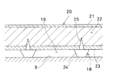
図2は前記断熱カバ−17の部分断面を示している。該断熱カバ−17のカバー本体20は、ガラスクロスにアルミ層、又は、シリコンコーティング層を形成した液密な外表面材21、グラスウール等から成る断熱材22、ガラスクロス等の耐熱材である内表面材23等から成る複層断面構造を有している。又、前記カバー本体20の内面に設けられる前記突出部18は、スペーサとなる頭部24、該頭部24より突出する尖出部25を有する画鋲形状をしている。
FIG. 2 shows a partial cross section of the
前記カバー本体20の内面から前記突出部18を差込む。前記尖出部25が前記内表面材23を貫通して前記断熱材22に刺さり、前記突出部18が前記カバー本体20の内面に保持される。前記突出部18は、前記カバー本体20の内面全域に渡り、所要の分布で、或は前記タービンハウジング9の高温となる部分に対応させ、所要の分布で設けられる。
The
尚、前記突出部18が設けられたことで、前記カバー本体20の柔軟性は損われることがない。
In addition, the softness | flexibility of the said cover
前記カバー本体20を前記タービンハウジング9に装着すると、前記内表面材23と前記タービンハウジング9の表面間に前記頭部24が介在することとなり、前記内表面材23と前記タービンハウジング9の表面との間には前記空気層19が形成される。
When the
又、前記カバー本体20が装着された状態では、前記突出部18は前記カバー本体20と前記タービンハウジング9間に挾持されることになり、前記突出部18が前記カバー本体20から抜脱することはなく、前記突出部18を保持する力は小さくてよい。
When the
而して、前記カバー本体20と前記タービンハウジング9間に前記空気層19が形成され、前記カバー本体20の断熱層の厚みを大きくすることなく簡便に断熱性能を向上させることができる。
Thus, the
又、前記突出部18は前記カバー本体20に対して任意の場所に、任意の分布で後付けでき、必要な部分に、必要な範囲で適宜な前記空気層19を形成することができる。
Further, the protruding
尚、前記突出部18の材質としては、セラミック等の断熱材であることが好ましいが、該突出部18自体は放熱性を問われないので、ステンレス鋼等の金属製であってもよい。
In addition, as a material of the said
図3は、本発明の第2の参考例を示している。 FIG. 3 shows a second reference example of the present invention.
該第2の参考例に於ける突出部26は、前記内表面材23自体によって形成される。即ち、前記内表面材23の屈撓性を利用して内面側の突出する襞を形成したものである。
The
前記突出部26を形成することで、前記内表面材23と前記タービンハウジング9との間に空気層19が形成される。
By forming the
尚、前記突出部26の剛性を高める為、前記突出部26の基部26aを縫込んでもよい。又、前記突出部26は連続したものであっても、断続したものであってもよい。
In order to increase the rigidity of the protruding
図4は、本発明の第1の実施例を示している。 Figure 4 shows a first embodiment of the present invention.
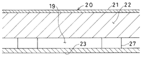
該第1の実施例では、断熱材22と内表面材23間に突出部27を設け、前記断熱材22と前記内表面材23間に空気層19を形成したものである。
In embodiments the first, the projecting
前記突出部27は、所要の大きさに切断した断熱材の断片であり、前記突出部27を、前記断熱材22の前記タービンハウジング9の高温となる部分に対応させ、所要の部分に、所要の範囲で取付ける。前記断熱材22と前記内表面材23とは前記突出部27によって離反され、前記断熱材22と前記内表面材23間に前記空気層19が形成され、カバー本体20の断熱性が向上する。
The
前記突出部27と前記断熱材22との固定は、縫合、或は一時的な接着等が考えられる。前記突出部27の取付け後、前記内表面材23が前記突出部27を覆う様に設けられる。前記内表面材23が設けられた後は、前記突出部27は前記内表面材23によって保護されるので、前記カバー本体20を前記タービンハウジング9に装着する場合にも、前記突出部27を剥離する様な大きな力は作用しない。又、前記突出部27は部分的に取付けられるので、前記カバー本体20の柔軟性を損うことはない。
The
図5は、本発明の第3の参考例を示しており、該第3の参考例も断熱材22と内表面材23間に空気層19を形成したものである。
Figure 5 shows a third exemplary embodiment of the present invention, reference example of the third well is obtained by forming an
図2で示した突出部18を前記断熱材22に直接差込む。前記突出部18を設ける範囲は、前記断熱材22の全面でもよく、或は前記タービンハウジング9の高熱部分に対応する部分に、所要の分布で前記突出部18が設けられてもよい。該突出部18によって前記断熱材22と前記内表面材23との間に前記空気層19が形成される。該空気層19が形成されることで、断熱カバ−17の断熱性能が向上する。
The
図6は、本発明の第4の参考例を示している。 FIG. 6 shows a fourth reference example of the present invention.
該第4の参考例では、第2の参考例と同様、突出部26を内表面材23に形成した襞で構成したものであるが、前記突出部26の突出方向を断熱材22に向けたものである。
In a reference example of the fourth, as in the second reference example, but which is constituted by folds formed on the inner surface member 23 a
前記突出部26により、前記断熱材22と前記内表面材23との間に空気層19が形成され、断熱カバ−17の断熱性能が向上する。
The protruding
尚、前記断熱材22を複層構造とし、断熱材内部の層間に空気層形成部材を介設し、断熱材の内部に空気層を形成してもよい。又、空気層形成部材としては、上記突出部の他に、金属タワシ、金属網、金属網を重ねたもの、パンチングメタル、エキスパンドメタル等、空気層を形成できる多空隙材料が使用可能である。
The
1 過給機
3 タービン
4 コンプレッサ
7 タービン翼車
8 コンプレッサ翼車
9 タービンハウジング
17 断熱カバ−
18 突出部
19 空気層
21 外表面材
22 断熱材
23 内表面材
24 頭部
25 尖出部
DESCRIPTION OF SYMBOLS 1 Supercharger 3
18
Claims (1)
Priority Applications (1)
| Application Number | Priority Date | Filing Date | Title |
|---|---|---|---|
| JP2012008797A JP2012102744A (en) | 2012-01-19 | 2012-01-19 | Heat insulation cover of supercharger |
Applications Claiming Priority (1)
| Application Number | Priority Date | Filing Date | Title |
|---|---|---|---|
| JP2012008797A JP2012102744A (en) | 2012-01-19 | 2012-01-19 | Heat insulation cover of supercharger |
Related Parent Applications (1)
| Application Number | Title | Priority Date | Filing Date |
|---|---|---|---|
| JP2008010764A Division JP5076919B2 (en) | 2008-01-21 | 2008-01-21 | Insulation cover for turbocharger |
Publications (1)
| Publication Number | Publication Date |
|---|---|
| JP2012102744A true JP2012102744A (en) | 2012-05-31 |
Family
ID=46393386
Family Applications (1)
| Application Number | Title | Priority Date | Filing Date |
|---|---|---|---|
| JP2012008797A Pending JP2012102744A (en) | 2012-01-19 | 2012-01-19 | Heat insulation cover of supercharger |
Country Status (1)
| Country | Link |
|---|---|
| JP (1) | JP2012102744A (en) |
Cited By (5)
| Publication number | Priority date | Publication date | Assignee | Title |
|---|---|---|---|---|
| JP2016518553A (en) * | 2013-05-14 | 2016-06-23 | ボーグワーナー インコーポレーテッド | Turbine housing of exhaust gas turbocharger |
| EP3893561A1 (en) | 2011-07-13 | 2021-10-13 | Sun Patent Trust | Terminal apparatus, base station apparatus, transmission method and reception method |
| CN114761745A (en) * | 2019-12-04 | 2022-07-15 | 联合利华知识产权控股有限公司 | Container for storing and serving frozen desserts |
| US12396553B2 (en) | 2019-05-14 | 2025-08-26 | Conopco, Inc. | Container for storing and serving frozen confectionery items |
| US12466560B2 (en) | 2019-12-04 | 2025-11-11 | Conopco, Inc. | Container for storing and serving scoopable frozen confectionery |
Citations (5)
| Publication number | Priority date | Publication date | Assignee | Title |
|---|---|---|---|---|
| JPS6240232U (en) * | 1985-08-30 | 1987-03-10 | ||
| JPH07189725A (en) * | 1993-12-27 | 1995-07-28 | Ishikawajima Harima Heavy Ind Co Ltd | Turbine housing lagging cover |
| JPH09151742A (en) * | 1995-11-29 | 1997-06-10 | Murai Shoji Kk | Heat insulating cover for turbocharger and manufacture thereof |
| JP2003293780A (en) * | 2002-03-29 | 2003-10-15 | Toyota Motor Corp | Turbine housing |
| JP2006112097A (en) * | 2004-10-14 | 2006-04-27 | Shizen Club:Kk | Thermal insulation panel and thermal insulation unit |
-
2012
- 2012-01-19 JP JP2012008797A patent/JP2012102744A/en active Pending
Patent Citations (5)
| Publication number | Priority date | Publication date | Assignee | Title |
|---|---|---|---|---|
| JPS6240232U (en) * | 1985-08-30 | 1987-03-10 | ||
| JPH07189725A (en) * | 1993-12-27 | 1995-07-28 | Ishikawajima Harima Heavy Ind Co Ltd | Turbine housing lagging cover |
| JPH09151742A (en) * | 1995-11-29 | 1997-06-10 | Murai Shoji Kk | Heat insulating cover for turbocharger and manufacture thereof |
| JP2003293780A (en) * | 2002-03-29 | 2003-10-15 | Toyota Motor Corp | Turbine housing |
| JP2006112097A (en) * | 2004-10-14 | 2006-04-27 | Shizen Club:Kk | Thermal insulation panel and thermal insulation unit |
Cited By (7)
| Publication number | Priority date | Publication date | Assignee | Title |
|---|---|---|---|---|
| EP3893561A1 (en) | 2011-07-13 | 2021-10-13 | Sun Patent Trust | Terminal apparatus, base station apparatus, transmission method and reception method |
| EP4236491A2 (en) | 2011-07-13 | 2023-08-30 | Sun Patent Trust | Base station apparatus, communication method and integrated circuit |
| JP2016518553A (en) * | 2013-05-14 | 2016-06-23 | ボーグワーナー インコーポレーテッド | Turbine housing of exhaust gas turbocharger |
| US12396553B2 (en) | 2019-05-14 | 2025-08-26 | Conopco, Inc. | Container for storing and serving frozen confectionery items |
| CN114761745A (en) * | 2019-12-04 | 2022-07-15 | 联合利华知识产权控股有限公司 | Container for storing and serving frozen desserts |
| US12466560B2 (en) | 2019-12-04 | 2025-11-11 | Conopco, Inc. | Container for storing and serving scoopable frozen confectionery |
| US12466559B2 (en) | 2019-12-04 | 2025-11-11 | Conopco, Inc. | Container for storing and serving frozen confectionery items |
Similar Documents
| Publication | Publication Date | Title |
|---|---|---|
| JP5033407B2 (en) | Ceramic matrix composite nozzle structure | |
| JP5782242B2 (en) | Shroud assembly with blocking device | |
| JP5909099B2 (en) | Assembly for blocking fluid flow | |
| JP5743442B2 (en) | Seal for turbine engine and method of assembling turbine engine | |
| US11459904B2 (en) | Seal with integral assembly clip and method of sealing | |
| JP5670692B2 (en) | Burst protection device, gas turbomachine and internal combustion engine | |
| RU2007135200A (en) | GAS-TURBINE ENGINE TURBINE STATOR AND GAS-TURBINE ENGINE | |
| JP5076919B2 (en) | Insulation cover for turbocharger | |
| US20140237784A1 (en) | Method of forming a microchannel cooled component | |
| JP5869100B2 (en) | SEALING DEVICE AND GAS TURBINE HAVING SEALING DEVICE | |
| CN103362563B (en) | Turbine shroud assembly and method of forming | |
| RU2013107703A (en) | SYSTEM CONTAINING A TURBO MACHINE, A DEVICE CONTAINING A TURBO MACHINE BLADE AND A GAS-TURBINE ENGINE | |
| CN105593475A (en) | Turbine housing of exhaust-gas turbocharger | |
| JP6248628B2 (en) | Turbocharger | |
| JP2008202467A (en) | Supercharger | |
| CN105189936B (en) | Cooling units for gas turbines | |
| JP2012527576A (en) | Turbocharger | |
| JP5648221B2 (en) | Engine turbocharge system | |
| JP2012102743A (en) | Heat insulation cover of supercharger | |
| CN203962161U (en) | A kind of engine heat shield | |
| CN201062536Y (en) | 2.8 liters diesel engine exhaust manifold having thermally-insulated shroud | |
| US20160061047A1 (en) | Gas turbine engine seal | |
| JP2015092075A (en) | Method and system for providing sealing in gas turbines | |
| JP2011080453A (en) | Fastening member and supercharger | |
| EP1952061B1 (en) | An annular burner assembly |
Legal Events
| Date | Code | Title | Description |
|---|---|---|---|
| A131 | Notification of reasons for refusal |
Free format text: JAPANESE INTERMEDIATE CODE: A131 Effective date: 20130312 |
|
| A977 | Report on retrieval |
Free format text: JAPANESE INTERMEDIATE CODE: A971007 Effective date: 20130314 |
|
| A521 | Written amendment |
Free format text: JAPANESE INTERMEDIATE CODE: A523 Effective date: 20130422 |
|
| A02 | Decision of refusal |
Free format text: JAPANESE INTERMEDIATE CODE: A02 Effective date: 20130702 |