JP2012102814A - Retainer and fitting structure using the same - Google Patents
Retainer and fitting structure using the same Download PDFInfo
- Publication number
- JP2012102814A JP2012102814A JP2010252371A JP2010252371A JP2012102814A JP 2012102814 A JP2012102814 A JP 2012102814A JP 2010252371 A JP2010252371 A JP 2010252371A JP 2010252371 A JP2010252371 A JP 2010252371A JP 2012102814 A JP2012102814 A JP 2012102814A
- Authority
- JP
- Japan
- Prior art keywords
- male
- female
- base
- receiving
- claw
- Prior art date
- Legal status (The legal status is an assumption and is not a legal conclusion. Google has not performed a legal analysis and makes no representation as to the accuracy of the status listed.)
- Pending
Links
Images




Landscapes
- Connection Of Plates (AREA)
Abstract
【課題】高さ方向の省スペース化を図れて位置合わせ可能なリテーナ及び取付構造を提供する。
【解決手段】雄部32が互いに反対位置に設けた雄側第1側部36及び雄側第2側部37と、雄側第1側部36より先端側で雄側第1側部36より側方に突出した爪部35と、を備え、雄側第2側部37が先端側で雄側第1側部36に近接する傾斜面を有し、雌部42が互いに離間した受け部44及び支持部45と、雌側ベース部41に開設したベース穴部48と、を備え、受け部44は雄部32及び支持部45より弾性変形可能に雌側ベース部41から突設されて雄側第1側部36が当接する雌側第1側部46と爪部35が係止する係止穴部49とを有し、支持部45は雄側第2側部37が当接する雌側第2側部47を有し、雌側第2側部47は先端側ほど雌側第1側部46との間が離間する傾斜面を有し、雄部32を収容部43に挿入すると爪部35が受け部44を弾性変形して係止穴部49に係止する。
【選択図】図6A retainer and a mounting structure are provided that can be positioned while saving space in the height direction.
A male side first side and a male side second side are provided at positions opposite to each other, and a male side first side and a male side first side and a male side first side. A claw portion 35 projecting sideways, the male second side portion 37 having an inclined surface close to the male first side portion 36 on the distal end side, and the female portion 42 spaced apart from each other. And a support hole 45 and a base hole 48 formed in the female base part 41. The receiving part 44 protrudes from the female base part 41 so as to be elastically deformable from the male part 32 and the support part 45, and is male. The female side first side portion 46 with which the side first side portion 36 abuts and a locking hole portion 49 with which the claw portion 35 engages, and the support portion 45 is a female side with which the male side second side portion 37 abuts. The female side second side portion 47 has an inclined surface that is separated from the female side first side portion 46 toward the distal end, and the male portion 32 is inserted into the accommodating portion 43. The claw portion 35 receiving portion 44 engages with the locking hole portion 49 elastically deformed.
[Selection] Figure 6
Description
本発明は、雄部を雌部の収容部に挿入して係止するリテーナと、このリテーナを用いて各種の取付部材を被取付部材に取り付ける取付構造に関する。 The present invention relates to a retainer that inserts and locks a male portion into a housing portion of a female portion, and an attachment structure that attaches various attachment members to a member to be attached using the retainer.
従来、雄部を雌部の収容部に挿入して係止するリテーナとして、パネル等の被取付部材に取付孔を設け、この取付孔を利用してリテーナを係止することで、取付部材を取り付けるものが知られている。
下記特許文献1には雌部材及び雄部材からなるクリップが開示されている。雌部材は、パネルの取付孔に挿入される筒状の胴部と、胴部の周囲から外側に突出して設けられて胴部内へ縮径可能な係止爪とを備え、雄部材は胴部を押圧するフランジ部と、胴部に挿入して係止爪の縮径を規制する軸部とを備えている。
このクリップでは、雄部材により押圧されて雌部材の胴部が取付孔に挿入される際、爪部が取付孔に圧接して縮径し、取付孔を通過後に復元する。雄部材の軸部分がさらに胴部内に挿入されると軸部分で係止爪の縮径が規制される。これにより雌部材がパネルの取付孔に固定され、雄部材が雌部材の胴部により固定される。
Conventionally, as a retainer that inserts and locks a male portion into a housing portion of a female portion, a mounting hole is provided in a member to be mounted such as a panel, and the retainer is locked by using the mounting hole, thereby fixing the mounting member. What to attach is known.
Patent Document 1 below discloses a clip made up of a female member and a male member. The female member includes a cylindrical body portion that is inserted into the mounting hole of the panel, and a locking claw that protrudes outward from the periphery of the body portion and can be reduced in diameter into the body portion. And a shaft portion that is inserted into the body portion and restricts the diameter of the locking claw.
In this clip, when the body part of the female member is inserted into the attachment hole by being pressed by the male member, the claw part is pressed against the attachment hole to reduce the diameter, and is restored after passing through the attachment hole. When the shaft portion of the male member is further inserted into the body portion, the diameter of the locking claw is restricted by the shaft portion. As a result, the female member is fixed to the mounting hole of the panel, and the male member is fixed by the body portion of the female member.
下記特許文献2には、内装品から互いに対向して突出する一対の係止板と、一対の係止板間に配置される内部材とからなるクリップ体が開示されている。内部材は一対の係止板間に配置される押圧板と、押圧板と鋭角に交差するフランジ部とを備える。
このクリップ体では、内部材を一対の係止板間に挿通した状態で、パネルの組付孔に挿入し、パネルと内装品との間でフランジ部を挟持すると、押圧板が変形して係止板を押圧し、組付孔の周縁部と係合される。
In this clip body, when the inner member is inserted between the pair of locking plates and inserted into the assembly holes of the panel and the flange portion is sandwiched between the panel and the interior product, the pressing plate is deformed and engaged. The stop plate is pressed and engaged with the peripheral edge of the assembly hole.
このようなクリップを用いて、バックドアのリヤスポイラーの側縁側にプロテクタを取り付けた例を図8(a)に示す。図8(a)は車両のバックドア13上方における車幅方向の側縁側を車幅方向に切断した断面の概略を示す。この構造では、バックドア13のアウターパネル14にリヤスポイラー21が固定され、リヤスポイラー21の側縁側にプロテクタ22が取り付けられている。
プロテクタ22はリヤスポイラー21の側縁側背面と側縁周囲を覆うものであり、リヤスポイラー21の側縁付近の形状に対応した形状で弾性材料により形成されている。このプロテクタ22は図示しない位置でバックドア13のインナーパネル15に固定され、リヤスポイラー21の側縁付近の背面側でクリップ60を用いて固定されている。
取付状態では、プロテクタ22とリヤスポイラー21の背面及び側縁周囲との間に所定の間隙が形成され、さらにプロテクタ22の端部26aとリヤスポイラー21の表面との間に雨水等が通水可能な間隙27が形成される。
このような取付構造では、弾性材料からなるプロテクタ22をバックドア13に固定した状態で、端部26a付近を上述のようなクリップ60を用いて固定することで、プロテクタ22の端部26aとリヤスポイラー21との間の間隔を保って配設することが可能である。
FIG. 8A shows an example in which a protector is attached to the side edge of the rear spoiler of the back door using such a clip. FIG. 8A shows an outline of a cross section obtained by cutting the side edge side in the vehicle width direction above the
The
In the mounted state, a predetermined gap is formed between the
In such a mounting structure, the
なお、クリップ60を用いずにプロテクタ22をリヤスポイラー21に装着してもよい。その場合、図8(b)に示すように、リヤスポイラー21の側縁付近の背面側とプロテクタ22の対応する位置とに面ファスナを配設し、これらを互いに係止することでプロテクタ22をリヤスポイラー21に取り付ける。
The
しかしながら、クリップを用いてプロテクタ22をリヤスポイラー21に取り付ける場合、図8(a)に示すように、リヤスポイラー21の背面に雌部材61等を挿入するための取付孔62を設け、リヤスポイラー21内部に雌部材61等を収容できる空間を確保しなければならない。雄部材63を雌部材61に係止するには、雄部材63を係止位置より前方側までオーバーストロークさせた後で係止位置に配置するため、雌部材61が収容される空間の他に、雄部材63の先端63aを収容する空間とオーバーストローク可能な空間も必要である。
However, when the
しかも、プロテクタ22が不透明な弾性材料により形成されているため、プロテクタ22の背面に雄部材63を固定し、この雄部材63を雌部材61や取付孔62に装着する場合、雄部材63や雌部材61を目視により確認して装着することができない。そのため、雄部材63の先端63aや雌部材61又は取付孔の開口には位置ずれしていても所定位置まで案内できる傾斜した案内面等が必要である。ところが、この案内面を所定の傾斜で大きくするとすれば、その分雄部材63や雌部材の挿入方向の長さが長くなり、リヤスポイラー21内部により大きな空間が必要になる。
仮にリヤスポイラー21の内部に雌部材61を収容せずに固定するとすれば、リヤスポイラー21とプロテクタ22との間の間隙が著しく大きなものとなる。
そのため、側縁側が薄肉に形成されたリヤスポイラー21の場合、クリップ60を用いて装着することは非常に困難であった。
Moreover, since the
If the
Therefore, in the case of the
また、従来のクリップ60では、雄部材63を押圧して雌部材61に係止するために所定の押圧力が必要であり、この押圧力が比較的大きなものとなっていた。そのため、目視により確認せずに雄部材63を雌部材61に係止する場合には、雄部材63を雌部材61に対して位置及び向きを合わせて挿入することができない分、より大きな押圧力が必要で、装着作業に手間を要していた。
Further, in the
一方、面ファスナ64を用いてプロテクタ22をリヤスポイラー21に取り付ける場合、図8(b)に示すように、リヤスポイラー21の内部には空間を設ける必要がなく、リヤスポイラーの薄肉部分であってもプロテクタ22を装着可能である。
ところがクリップ60の場合には、雌部材61に対して雄部材63が固定される位置が特定されるため、リヤスポイラー21とプロテクタ22との相対位置を規制できるが、面ファスナ64の場合、リヤスポイラー21とプロテクタ22との間の相対位置を規制することができない。プロテクタ22の端部26aとリヤスポイラー21の表面との間の間隙27は、広くなると外観品質が低下し、狭いと雨水が通水できないため、リヤスポイラー21とプロテクタ22との間の相対位置を精度良く合わせて固定する必要があるが、そのような位置合わせが困難であった。
On the other hand, when the
However, in the case of the
そこで本発明では、高さ方向の省スペース化を図れて位置合わせ可能なリテーナを提供することを目的とし、高さ方向の省スペース化を図れて容易に係止できるリテーナを提供することを他の目的とする。さらに、本発明では、被取付部材に対して取付部材を容易に位置合わせして取り付けられ、被取付部材の内部に空間を設けることなく高さ方向の省スペース化を図ることが可能なリテーナを用いた取付構造を提供することを他の目的とする。 In view of the above, the present invention aims to provide a retainer that can be positioned in a space-saving manner in the height direction, and can provide a retainer that can be easily locked in a space-saving manner in the height direction. The purpose. Furthermore, in the present invention, there is provided a retainer that can be attached by easily aligning the mounting member with respect to the mounted member, and can save space in the height direction without providing a space inside the mounted member. Another object is to provide the mounting structure used.
上記目的を達成する本発明のリテーナは、雄部が側周囲の互いに反対位置に設けられた雄側第1側部及び雄側第2側部と、雄側第1側部より先端側に設けられて雄側第1側部より側方に突出した爪部と、を備え、雄側第2側部は雄部の先端側で雄側第1側部に近接する傾斜面を有し、雌部が収容部を形成するように雌側ベース部に互いに離間して配設された受け部及び支持部と、雌側ベース部の収容部に対応する位置に開設されたベース穴部と、を備え、受け部は雄部及び支持部より弾性変形可能に雌側ベース部から突設され、且つ雄側第1側部が当接する雌側第1側部と爪部が係止する係止穴部とを有し、支持部は雄側第2側部が当接する雌側第2側部を有し、雌側第2側部は支持部の先端側ほど雌側第1側部との間が離間する傾斜面を有し、雄部が収容部に挿入されるとき、雄部が雌側第2側部に案内されることで爪部が受け部を弾性変形させて係止穴部に係止され、係止状態では、雄部の先端側がベース穴部に収容され、雄側第1側部及び雄側第2側部がそれぞれ雌側第1側部及び雌側第2側部に当接することを特徴としている。 The retainer of the present invention that achieves the above object is provided with a male side first side part and a male side second side part that are provided at opposite positions around the side of the male part, and a distal side from the male side first side part. And a claw projecting laterally from the male first side, and the male second side has an inclined surface close to the male first side on the distal end side of the male, A receiving portion and a support portion that are spaced apart from each other so that the portion forms a receiving portion, and a base hole portion that is opened at a position corresponding to the receiving portion of the female base portion. The receiving portion protrudes from the female base portion so as to be elastically deformable from the male portion and the support portion, and is a locking hole for locking the female first side portion and the claw portion with which the male first side portion abuts. The support part has a female second side part with which the male second side part abuts, and the female side second side part is closer to the female side first side part toward the distal end side of the support part. Have inclined surfaces When the male part is inserted into the housing part, the male part is guided to the female second side part, so that the claw part elastically deforms the receiving part and is locked in the locking hole part. The distal end side of the male part is accommodated in the base hole part, and the male first side part and the male second side part are in contact with the female first side part and the female second side part, respectively.
このリテーナでは、雄部が側周囲の互いに反対位置に先端側程近接する雄側第1側部と雄側第2側部とを備えて先細り形状に形成されている。一方、雌部の収容部が受け部の先端側程離間する受け部の雌側第1側部と支持部の雌側第2側部とにより先広がり形状に形成されている。そのため雄部の先端側を雌部の収容部内に挿入すると、雄部が雌側第2側部により案内されて、雌部に対して雄部が位置合わせされ、雄部の爪部を受け部の係止穴部に係止することができる。
雌部の受け部が雄部及び支持部より弾性変形可能となるように雌側ベース部から突設され、雄部が雌部の収容部に挿入されたとき爪部が受け部を弾性変形させて係止穴部に係止するように構成されている。そのため、雄部の雄側第2側部及び支持部の雌側第2側部を弾性変形しない程度に硬く形成でき、雄部が支持部に当接して案内される際に円滑に移動できる。これにより雄部の雄側第2側部及び支持部の雌側第2側部を挿入方向に対して大きく傾斜させることが可能となり、雄部の先端側を十分に狭くでき、また雌部の収容部を十分に広く開口させることができる。その結果、雄側ベース部からの雄部の突出量や雌側ベース部からの支持部の突出量を小さく抑えつつ、雄部と雌部の収容部との間の位置ずれをより広い範囲で位置合わせすることができる。
しかも、雌側ベース部の収容部に対応する位置にベース穴部を有し、係止状態で、雄部の先端側をベース穴部に収容するように構成されている。そのため、雄部の爪部を受け部の係止穴部に係止した状態で、雄側ベース部と雌側ベース部との間の間隙をより小さく抑えることができる。
従って、本発明のリテーナによれば、高さ方向の省スペース化を図れて位置合わせ可能なリテーナを提供することができる。
In this retainer, the male part has a male side first side part and a male side second side part that are closer to each other at positions opposite to each other around the side, and is formed in a tapered shape. On the other hand, the female accommodating portion is formed in a tapered shape by the female first side portion of the receiving portion and the female second side portion of the supporting portion that are separated from each other toward the distal end side of the receiving portion. Therefore, when the distal end side of the male part is inserted into the female part accommodating part, the male part is guided by the female second side part, the male part is aligned with the female part, and the claw part of the male part is received. Can be locked in the locking hole.
The female receiving portion protrudes from the female base so that the female receiving portion can be elastically deformed from the male portion and the supporting portion, and when the male portion is inserted into the female receiving portion, the claw portion elastically deforms the receiving portion. And is configured to be locked in the locking hole. Therefore, the male second side part of the male part and the female second side part of the support part can be formed so hard that they are not elastically deformed, and can move smoothly when the male part is brought into contact with the support part and guided. As a result, the male second side portion of the male portion and the female second side portion of the support portion can be greatly inclined with respect to the insertion direction, the front end side of the male portion can be sufficiently narrowed, and the female portion The accommodating portion can be opened sufficiently wide. As a result, the positional deviation between the male part and the female part accommodating part can be reduced in a wider range while suppressing the protruding amount of the male part from the male base part and the protruding part of the support part from the female base part. Can be aligned.
And it has a base hole part in the position corresponding to the accommodating part of a female side base part, and is comprised so that the front end side of a male part may be accommodated in a base hole part in the latching state. Therefore, the gap between the male side base portion and the female side base portion can be further reduced while the male claw portion is locked in the locking hole portion of the receiving portion.
Therefore, according to the retainer of the present invention, it is possible to provide a retainer that can be positioned while saving space in the height direction.
本発明のリテーナでは、受け部が雌側ベース部から略直交方向に突設されて雌側ベース部に対して根元部で固定された一対の固定片と、一対の固定片間に架設されて雌側第1側部を有する架橋片とを備え、架橋片が爪部より長く形成されて架橋片及び一対の固定片により係止穴部の周縁が形成されているのが好適である。
このようにすれば、受け部がより弾性変形し易くなるため、雄部の雄側第2側部及び支持部の雌側第2側部を挿入方向に対してより大きく傾斜させることができ、より高さ方向の省スペース化を図れる。
In the retainer of the present invention, the receiving portion projects from the female base portion in a substantially orthogonal direction, and is fixed between the pair of fixed pieces fixed at the root portion with respect to the female side base portion, and the pair of fixed pieces. Preferably, the cross-linking piece has a female first side portion, the cross-linking piece is formed longer than the claw portion, and the periphery of the locking hole portion is formed by the cross-linking piece and the pair of fixing pieces.
In this way, since the receiving part is more easily elastically deformed, the male second side part of the male part and the female second side part of the support part can be more greatly inclined with respect to the insertion direction, Space saving in the height direction can be achieved.
本発明の他の目的を達成するリテーナは、雄部は側周囲より側方に突出する爪部を備え、雌部は雌側ベース部から略直交方向に突設されて弾性変形可能な受け部を備え、受け部は、雌側ベース部に根元部で固定された一対の固定片と、一対の固定片間に架設されて爪部より長い架橋片と、架橋片及び一対の固定片により周縁が形成されて爪部が係止可能な係止穴部と、を備え、雄部が収容部に挿入されるとき、爪部が架橋片を押圧することで、受け部を弾性により側方に傾倒させると共に架橋片を弾性により側方に撓ませて、爪部が係止穴部に係止されることを特徴としている。 In a retainer that achieves another object of the present invention, the male part includes a claw part protruding sideways from the side periphery, and the female part protrudes from the female side base part in a substantially orthogonal direction and is elastically deformable. The receiving portion includes a pair of fixed pieces fixed to the female base portion at the base portion, a bridge piece extending between the pair of fixed pieces and longer than the claw portion, and a bridge piece and the pair of fixed pieces. And when the male part is inserted into the housing part, the claw part presses the bridging piece to elastically move the receiving part to the side. It is characterized in that the claw portion is locked in the locking hole portion by tilting and bending the bridging piece to the side by elasticity.
このリテーナによれば、受け部が雌側ベース部から突設されて弾性変形可能であり、一対の固定部が雌側ベース部に根元部で固定され、架橋片が爪部より長く形成されている。雄部が収容部に挿入されるとき、爪部が架橋片を押圧すると、受け部が弾性により側方に傾倒すると共に架橋片が弾性により側方に撓む。これにより爪部で受け部を押圧して弾性変形させた際、変形部位を分散でき、受け部を二段階で変形させることができる。
そのため爪部が係止される架橋片の一部を容易に所望量変位させることができ、受け部の雌側ベース部からの突出量を少なく抑えて弾性変形する量を確保できる。よって雌部の高さ方向の省スペース化を図ることができる。また、二段階に変形させることで受け部を変形するのに要する力を小さくできるため、雄部を雌部の収容部に挿入して爪部を係止穴部に係止させる際の押圧力を小さく抑えられ、リテーナの装着作業を容易にできる。
しかも受け部が弾性変形し易くても、受け部の固定部が雌側ベース部から略直交方向に突設されているため、雄部に雌部の収容部から離脱させる方向の力が作用した際には、受け部が変形し難くて係止状態が解除することを防止でき、十分な固定力を確保できる。
従って、高さ方向の省スペース化を図れて容易に係止できるリテーナを提供することができる。
According to this retainer, the receiving portion protrudes from the female base portion and is elastically deformable, the pair of fixing portions are fixed to the female base portion at the root portion, and the bridging piece is formed longer than the claw portion. Yes. When the male part is inserted into the housing part, when the claw part presses the cross-linked piece, the receiving part is tilted sideways due to elasticity and the cross-linked piece is bent sideways due to elasticity. Thereby, when the receiving part is pressed and elastically deformed by the claw part, the deformed portion can be dispersed and the receiving part can be deformed in two stages.
Therefore, a part of the bridging piece to which the claw portion is locked can be easily displaced by a desired amount, and the amount of elastic deformation can be ensured by suppressing the protrusion amount of the receiving portion from the female base portion. Therefore, space saving in the height direction of the female portion can be achieved. Also, since the force required to deform the receiving part can be reduced by deforming in two stages, the pressing force when the male part is inserted into the female part accommodating part and the claw part is engaged with the engaging hole part Can be kept small, and the retainer can be easily mounted.
In addition, even if the receiving part is easily elastically deformed, the fixing part of the receiving part protrudes from the female side base part in a substantially orthogonal direction, so that a force in a direction to detach the male part from the female part receiving part acts on the male part. In this case, it is difficult to deform the receiving portion and the locked state can be prevented from being released, and a sufficient fixing force can be secured.
Therefore, it is possible to provide a retainer that can be easily locked while saving space in the height direction.
本発明の他の目的を達成するリテーナを用いた取付構造は、上述のようなリテーナを備え、被取付部材及び取付部材の各所定位置に、雄側ベース部と雌側ベース部とが対を構成するように配設され、雄部が雌部の収容部に係止されることで被取付部材に取付部材が取り付けられていることを特徴としている。 A mounting structure using a retainer that achieves another object of the present invention includes the retainer as described above, and a male base portion and a female base portion are paired at each predetermined position of the mounted member and the mounting member. It is arrange | positioned so that it may comprise, The attachment member is attached to the to-be-attached member by the male part being latched by the accommodating part of a female part, It is characterized by the above-mentioned.
このリテーナを用いた取付構造によれば、上述のようなリテーナにより被取付部材と取付部材とを接合するので、被取付部材及び取付部材に雄側ベース部及び雌側ベース部を配設すれば被取付部材に取付部材を取り付けることができ、被取付部材の内部に空間を設ける必要がない。雄部と雌部との位置ずれがあっても位置合わせできるため、被取付部材と取付部材とを対向させて近接させれば、容易に所定の相対位置関係に合わせて取り付けることができる。しかも位置合わせできる範囲を広く確保しても、雄ベース部からの雄部の突出量や雌ベース部からの雌部の突出量を小さく抑えることができるため、接合状態で被取付部材と取付部材との間の間隔を小さく抑えることができる。
従って、被取付部材に対して取付部材を容易に位置合わせして取り付けられ、被取付部材の内部に空間を設けることなく高さ方向の省スペース化を図れる取付構造を提供することができる。
According to the mounting structure using this retainer, the mounted member and the mounting member are joined by the retainer as described above. Therefore, if the male base portion and the female base portion are disposed on the mounted member and the mounting member, The attachment member can be attached to the attached member, and there is no need to provide a space inside the attached member. Since the alignment can be performed even if there is a misalignment between the male part and the female part, if the mounted member and the mounting member are made to face each other and close to each other, they can be easily mounted in accordance with a predetermined relative positional relationship. Moreover, even if a wide range of alignment can be ensured, the protruding amount of the male part from the male base part and the protruding amount of the female part from the female base part can be kept small. The space between the two can be kept small.
Therefore, it is possible to provide an attachment structure in which the attachment member can be easily aligned and attached to the attachment member, and a space can be saved in the height direction without providing a space inside the attachment member.
本発明のリテーナを用いた取付構造では、被取付部材がバックドアに固定されたリヤスポイラーであり、取付部材がバックドアのインナーパネル及びリヤスポイラーの側縁側に取り付けられる不透明弾性材料からなるバックドアプロテクタであり、バックドアプロテクタが、インナーパネルに固定される固定部と、リヤスポイラーの側縁と所定の間隙を設けて対向配置される側縁被覆部と、を備え、雄部は雄側第2側部が側縁被覆部に沿うようにバックドアプロテクタの所定位置に配設され、雌部は雌側第2側部がリヤスポイラーの側縁に沿うようにリヤスポイラーの所定位置に配設する取付構造に好適に適用できる。 In the mounting structure using the retainer of the present invention, the mounted member is a rear spoiler fixed to the back door, and the mounting member is a back door protector made of an opaque elastic material that is mounted on the inner side panel of the back door and the side edge of the rear spoiler. A back door protector comprising: a fixed portion fixed to the inner panel; and a side edge covering portion disposed to face the side edge of the rear spoiler with a predetermined gap, and the male portion is the male second side portion. Is disposed at a predetermined position of the back door protector so as to be along the side edge covering portion, and the female portion is suitable for a mounting structure in which the female side second side portion is disposed at a predetermined position of the rear spoiler so as to be along the side edge of the rear spoiler. Applicable to.
本発明のリテーナによれば、雄側ベース部からの雄部の突出量や雌側ベース部からの支持部の突出量を小さく抑えつつ、雄部の先端側を狭くできると共に雌部の収容部を広く開口させることができる。また、雄部の爪部を支持部の係止穴部に係止した状態で雄部の先端側をベース穴部に収容することができる。そのため、高さ方向の省スペース化を図れて位置合わせできるリテーナを提供することが可能である。 According to the retainer of the present invention, the male part can be narrowed while the male part protruding from the male base part and the supporting part from the female base part are kept small. Can be opened widely. Moreover, the front end side of a male part can be accommodated in a base hole part in the state which latched the nail | claw part of the male part in the locking hole part of a support part. Therefore, it is possible to provide a retainer that can be positioned while saving space in the height direction.
本発明の他のリテーナによれば、雌部の受け部において雄部の爪部が係止する部位を二段階に変形させることで容易に弾性変形できるため、雄部を雌部の収容部に係止させる際の押圧力を小さく抑えることができる。雌部の受け部が容易に弾性変形できるため、雌側ベース部からの受け部の突出量を少なく抑えて所定の変形量を確保できる。そのため、高さ方向の省スペース化を図れて容易に係止できるリテーナを提供することが可能である。 According to the other retainer of the present invention, the male part can be made into the female part accommodating part because it can be easily elastically deformed by deforming the part where the male claw part latches in the female part receiving part in two stages. The pressing force at the time of locking can be kept small. Since the receiving portion of the female portion can be easily elastically deformed, a predetermined amount of deformation can be ensured by suppressing the protruding amount of the receiving portion from the female side base portion. Therefore, it is possible to provide a retainer that can be easily locked while saving space in the height direction.
本発明のリテーナを用いた取付構造によれば、上述のようなリテーナを用いたので、被取付部材に対して取付部材を容易に位置合わせして取り付けられ、被取付部材の内部に空間を設けることなく高さ方向の省スペース化を図ることが可能な取付構造を提供することができる。 According to the mounting structure using the retainer of the present invention, since the retainer as described above is used, the mounting member can be easily aligned with respect to the mounted member, and a space is provided inside the mounted member. Thus, it is possible to provide a mounting structure capable of saving the space in the height direction without any problems.
以下、本発明の実施形態について図を用いて詳細に説明する。この実施形態では、リテーナを用いてリヤスポイラーにバックドアプロテクタ(以下、プロテクタと称する。)を取り付けた取付構造の例を用いて説明する。 Hereinafter, embodiments of the present invention will be described in detail with reference to the drawings. In this embodiment, a description will be given using an example of an attachment structure in which a back door protector (hereinafter referred to as a protector) is attached to a rear spoiler using a retainer.
図1乃至図3に示すように、この取付構造では、ルーフパネル11及びサイドパネル12の後端にバックドア13が開閉可能に配設され、バックドア13のアウターパネル14の上端側にリヤスポイラー21が固定されている。リヤスポイラー21の側縁付近にプロテクタ22が裏側からリテーナ20を用いて取り付けられている。
As shown in FIGS. 1 to 3, in this mounting structure, the
リヤスポイラー21は、ルーフパネル11の後端に沿って車幅方向に延び、側縁がサイドパネル12の上部側に隣接配置されている。リヤスポイラー21の車幅方向両側縁側は、外観品質を確保するために中間部分に比べて薄肉に形成されている。このリヤスポイラー21は図示しない位置でバックドア13のアウターパネル14に固定されている。
The
プロテクタ22は、リヤスポイラー21より軟質の不透明弾性材料により、リヤスポイラー21の側縁付近の形状に対応した立体的な形状に成形されている。プロテクタ22には、インナーパネル15に取り付けられる固定部23と、リヤスポイラー21の側縁側を覆う被覆部24と、が設けられている。固定部23は複数設けられているが詳細な図示は省略している。
The
被覆部24はプロテクタ22の側縁側背面を覆う背面被覆部25と側縁周囲を覆う側縁被覆部26とを有する。背面被覆部25及び側縁被覆部26はそれぞれプロテクタ22の背面及び側縁との間に通水可能な間隙27を設けて対向配置されている。側縁被覆部26の端部26aはリヤスポイラー21の表面側に配置されており、端部26aとリヤスポイラー21の表面との間に所定間隙の開口27aが形成されている。この開口27aは通水機能及び外観を確保するため全長で一定間隙に配置されることが望ましい。
The covering
プロテクタ22は、固定部23においてバックドア13のアウターパネル14に固定され、背面被覆部25のリヤスポイラー21の側縁近傍の位置で複数のリテーナ20により固定されることでバックドアに取り付けられている。
The
プロテクタ22の背面被覆部25の側縁被覆部26近傍の位置と、リヤスポイラー21の対応する位置には、それぞれ後述するリテーナ20の雄側ベース部31又は雌側ベース部41を固定可能な取付座28が設けられている。各取付座28には雄側ベース部31又は雌側ベース部41の側縁を当接することで、リテーナ20を位置決め可能な台座位置決め部29が設けられていてもよい。
A mounting seat capable of fixing a
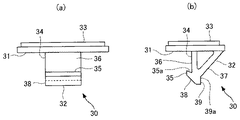
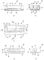
本実施形態のリテーナ20は図4に示すような雄部材30と図5に示すような雌部材40とを有する。雄部材30は雄側ベース部31と雄側ベース部31に突設された雄部32を備える。雌部材40は雌側ベース部41と雌側ベース部41に設けられた雌部42とを備える。雌部42には雄部32を挿入して係止するための収容部43が設けられている。雄側ベース部31及び雌側ベース部41には装着用の両面テープ33が貼着されている。
The
雄部32は、雌側ベース部41に立設されて側面視略三角形形状の脚部34と、脚部34の先端側に設けられた爪部35とを備え、硬質に形成されている。この雄部32には脚部34の側周囲の互いに反対位置に雄側第1側部36及び雄側第2側部37が設けられている。ここでは、雄側第1側部36及び雄側第2側部37がいずれも平面からなり、雄側第2側部37は雄部32の先端側で雄側第1側部36に近接する傾斜面からなる。
爪部35は、雄側第1側部36より先端側に設けられ、雄側第1側部36より側方に突出している。爪部35の係止位置となる内側面35aは雄側第1側部36に対して鋭角に形成されている。
雄部32の先端には、爪部35の側方への突出量以上の先端案内部38を備えている。先端案内部38は平面状に形成され、雄側第2側部37とは逆勾配の傾斜面となっている。
雄側第2側部37の先端側には平面状の先端位置決め部39を備える。この先端位置決め部39は角部39aを介して雄側第2側部37と連続して設けられている。
The
The
The distal end of the
A flat
雌部42は、収容部43を形成するように雌側ベース部41に互いに離間して配設された受け部44及び支持部45と、雌側ベース部41の収容部43に対応する位置に開設されたベース穴部48と、を備える。
The
受け部44は雄部32及び支持部45より弾性変形可能となるように雌側ベース部41から突設されており、雄部32の雄側第1側部36が当接する雌側第1側部46と、爪部35が係止する係止穴部49とを有する。
本実施形態の受け部44は、雌側ベース部41から略直交方向に突設された平板状の受けプレートからなる。平板状とは厚みが幅及び長さに比較して十分に薄い形状であればよい。受け部44の厚みは雌部42の材料の引っ張り強度や弾性等に応じて適宜設定でき、薄い程変形し易くでき、受け部44が側方へ傾倒し易くなる。
The receiving
The receiving
受け部44は、雌側ベース部41に対して根元部で固定された一対の固定片51と、一対の固定片51間に架設されて雌側第1側部46を有する架橋片52とを備える。
受け部44の係止穴部49は貫通孔であるのがよい。貫通孔であれば、受け部44が変形し易くでき、受け部44が弾性変形する際、固定片51と架橋片52とで変形部位を分散し易くできる。ここでは、係止穴部49は一対の固定片51及び架橋片52により周縁が形成された略四角形形状の貫通孔となっている。爪部35の内側面35aが係止される架橋片52の係止面52aは、爪部35の内側面と同様の傾斜面からなる。
The receiving
The locking
架橋片52の幅、即ち受け部44の突出方向に沿う幅は架橋片52の厚みより大きく形成されている。厚みより幅を大きくすることで架橋片52を幅方向よりも厚み方向へ変形し易くできる。
架橋片52及び係止穴部49の雌側ベース部41に沿う長さ、即ち一対の固定片51間の距離は、雄部32の爪部35の雄側ベース部31に沿う長さより大きく形成されている。これにより爪部35が架橋片52を押圧した際、架橋片52が弾性により側方に撓み易くなる。
The width of the
The length along the
架橋片52及び係止穴部49の長さは、爪部35の長さに対して1.5倍以上3倍以下とするのがよい。架橋片52及び係止穴部49の長さと爪部35の長さとの差が過剰に小さいと、雄部32を雌部42の収容部43に挿入して爪部35により受け部44を押圧した際、一対の固定片51の傾倒と架橋片52の撓みにより受け部44の変形位置を分散できず、後述するような作用を十分に得られない。一方、架橋片52及び係止穴部49の長さと爪部35の長さとの差が過剰に大きいと、架橋片52が撓み易くなり、係止状態における係止力が得られない。
The length of the
支持部45は雌側ベース部41に突設されており、雄部32の雄側第2側部37が当接する雌側第2側部47を有して硬質に形成されている。ここでは雌側第2側部47は平面に形成され、支持部45の先端側ほど受け部44の雌側第1側部46との間が離間する傾斜面となっている。
この支持部45には、雌側第2側部47の両端側に互いに対向する一対の端部案内部53が設けられている。一対の端部案内部53は平面からなり、それぞれ係止穴部49に隣接する位置に配設されて、支持部45の先端側ほど互いに離間する傾斜面となっている。
The
The
雌側ベース部41に対する雌側第2側部47及び一対の端部案内部53の傾斜角度は、雄側ベース部31を雌側ベース部41に対向させて近接させた際、雄部32の先端が雌部42の雌側第2側部47により案内されて、雄部32の爪部35が雌部42の係止穴部49の位置に案内可能な傾斜であればよい。特に限定されるものではないが、雌側ベース部41に対する雌側第2側部47の傾斜面の傾斜角度を、例えば30度以上60度以下としてもよい。
傾斜角度が過剰に小さいと、十分な案内作用が得られず、装着時の装着荷重が大きくなる。一方、傾斜角度が過剰に大きいと、装着荷重は小さく抑えられるものの、雌部42の収容部43における案内作用を確保するための所望の開口量を確保するには、雌側ベース部41からの突出量が大きくなり、高さ方向の省スペース化を実現し難くなる。
The inclination angle of the female
If the inclination angle is excessively small, sufficient guiding action cannot be obtained, and the mounting load at the time of mounting becomes large. On the other hand, if the inclination angle is excessively large, the mounting load can be kept small, but in order to secure a desired opening amount for ensuring the guiding action in the
雌側第2側部47は雄側第2側部37と同じ傾斜を有し、互いに面接触するのが好適である。このようにすれば雄部32を雌部42の収容部43に係止した状態で、雄部32が雌部42の収容部43に安定して当接配置でき、係止状態で互いに安定する。
The female
雌側ベース部41のベース穴部48は、雄部32の爪部35を係止穴部49に係止させる際に雄部32の先端が挿入できれば、有底穴であっても貫通孔であってもよい。貫通孔であれば、雄部32の先端をより多く挿入させることができる。しかも貫通孔であれば、雌側ベース部41から受け部44の根元部付近に作用する張力等を抑えることができ、受け部44を変形し易くできる。
The
このベース穴部48は、固定片51間に対応する位置に、受け部44の両側方に連続するように開設されており、係止穴部49から連通している。ここではベース穴部48の長さが一対の固定部間の距離となっており、係止穴部49の長手方向の長さと等しくなっている。ベース穴部48は平面視略四角形状であり、各固定片51の根元部に近接する角部にそれぞれスリット54が設けられている。スリット54を設けることで受け部44がより弾性変形し易くなる。
The
ベース穴部48内面には底部位置決め部55が設けられている。ここでは支持部45の雌側第2側部47に隣接する側面にも連続して底部位置決め部55が設けられている。この底部位置決め部55は雄部32の先端位置決め部39と当接可能な平面により構成されている。
なお、雌側ベース部41は収容部43に対応する部位の厚みが他の部位の厚みより薄く形成されている。これにより受け部44がより傾倒し易くなっている。
A
In addition, the thickness of the site | part corresponding to the
リテーナ20の雄部材30と雌部材40を構成する材料は、雄部32を雌部42の収容部43に挿入する際、雄部32及び雌部の支持部45が弾性変形せず、受け部44が弾性変形可能となる関係が得られる材料であれば特に限定されない。特に受け部44において、一対の固定片51が側方側へ弾性により傾倒でき、架橋片52が一対の固定片51より側方側に撓むことができ、しかも雄部32を雌部42の収容部43に係止した状態では、抜け方向の変形を防止できる剛性が得られる材料を選択するのがよい。
本実施形態では、雄部材30と雌部材40が同一樹脂によりそれぞれ一体に形成されている。雨水が接触するため吸水性の低い樹脂を用いるのが好適であり、例えばPBT、ABS等の樹脂を用いることができる。
なお、雌部42の受け部44が一対の固定片51及び架橋片52により構成されているため、後述するように、係止時に受け部44の変形部位を分散できる。そのため各部に負荷される応力を分散できることで、硬質の材料であっても使用可能であり、逆に、より軟質の材料であっても強度を確保できれば使用可能である。
The material constituting the
In this embodiment, the
In addition, since the receiving
次に、このようなリテーナ20を用いてバックドア13に固定されたリヤスポイラー21にプロテクタ22を取り付ける方法について説明する。
図6(a)に示すように、リヤスポイラー21の取付座28に雄部材30の雄側ベース部31を両面テープ33により固定し、プロテクタ22の取付座28に雌部材40の雌側ベース部41を両面テープ33で固定する。台座位置決め部29が設けられている場合、各ベース部31,41の側縁を台座位置決め部29に当接させて固定する。
これによりリヤスポイラー21とプロテクタ22とを対向させた際、互いに対向する位置に雄部材30と雌部材40とが対を構成するように配置される。これらの位置はプロテクタ22の裏側において周縁より内側の中間位置となっている。
Next, a method of attaching the
As shown in FIG. 6A, the
Thereby, when the
プロテクタ22を固定部23においてバックドア13に固定した状態で、プロテクタ22の被覆部24をリヤスポイラー21に対向させ、リテーナ20が視認できない状態で雄側ベース部31と雌側ベース部41とを互いに対向近接させる。これにより雄部32の先細り状形状の先端が雌部42の先広がり形状の収容部43に挿入する。
このとき、雌部42の収容部43に対する雄部32の位置ずれが大きくても、仮想線で示すように、先端案内部38が受け部44の先端に当接したり、雄部32の先端が支持部45の雌側第2側面47に当接することで、これらの傾斜により所定の位置に案内される。
また収容部43に沿う両端間の長さが爪部35の長さに対して長く形成されているが、長さ方向の位置ずれがさらに大きい場合には、雄部32が端部案内部53に当接することで、所定の位置に案内される。
In a state where the
At this time, even if the positional deviation of the
Further, although the length between both ends along the
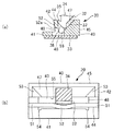
雄部32が収容部43に挿入されると、図6(b)に示すように、雄部32が支持部45の雌側第2側部47に案内されつつ、爪部35が受け部44の架橋片52に当接し、爪部35により架橋片52を押圧する。すると図7(a)に示すように、爪部35により受け部44の固定部23を傾倒させる。また図7(b)に示すように、爪部35により受け部44の架橋片52を弾性により撓ませる。従って、受け部44が二段階に弾性変形することになる。
雄部材30と雌部材40が傾いて挿入された場合には、図6(c)に示すように、雄部材30の雄側第2側部37が支持部45に当接して案内され、その後同様に爪部35が受け部44の架橋片52に当接して受け部44を弾性変形させる。
このとき、雄部32の雄側第1側部36、雄側第2側部、爪部35は変形せず、雌部42の支持部45の雌側第2側部47や底部位置決め部55も変形せずに、雌部42の収容部に雄部32が挿入される。
When the
When the
At this time, the male side
図6(d)に示すように、雄側ベース部31と雌側ベース部41とを十分に近接させると、雄部32の先端側がベース穴部48に収容され、爪部35が架橋片52の側方を通過してオーバーストロークすることで、固定片51及び架橋片52の弾性変形が復元する。これにより、雄部32の爪部35が受け部44の係止穴部49に完全に係止される。
係止状態では、雄側第1側部36が雌側第1側部46に当接し、雄側第2側部37が雌側第2側部47に当接する。また雄部32の先端側がベース穴部48に収容され、先端位置決め部39が底部位置決め部55に当接する。
As shown in FIG. 6D, when the male
In the locked state, the male side
このようにして雄部32を雌部42の収容部43に係止することで、図3(a)(b)に示すように、プロテクタ22の被覆部24がリヤスポイラー21側縁側の所定位置に取り付けられる。本実施形態の取付構造では、雄部32の雄側第2側部37がプロテクタ22の側縁被覆部26に沿うように配設され、雌部42の雌側第2側部47がリヤスポイラー21の側縁に沿うように配設されている。そのため、取付状態ではプロテクタ22の側縁被覆部26がリヤスポイラー21の側縁に対して精度よく配置される。特に側縁被覆部26の端部26aとリヤスポイラー21の表面との間の開口27aが精度よく形成される。
By locking the
以上のようなリテーナ20によれば、雄部32が側周囲の互いに反対位置に雄側第1側部36と雄側第2側部37とを備えて先細り形状に形成されている。一方、雌部42の収容部43が受け部44の雌側第1側部46と支持部45の雌側第2側部47とにより先広がり形状に形成されている。そのため、雄部32の先端側を雌部42の収容部43内に挿入すると、雄部32が雌側第2側部47により案内されて、雌部42に対して雄部32を所定の位置に位置合わせして、雄部32の爪部35を受け部44の係止穴部49に係止することができる。
According to the
雌部42の受け部44が雄部32及び支持部45より弾性変形可能となるように雌側ベース部41から突設され、雄部32が雌部42の収容部43に挿入されたとき爪部35が受け部44を弾性変形させて係止穴部49に係止するように構成されている。そのため雄部32の雄側第2側部37及び支持部45の雌側第2側部47を弾性変形しない程度に硬く形成でき、雄部32が支持部45に当接して案内される際に円滑に移動できる。これにより、雄部32の雄側第2側部37及び支持部45の雌側第2側部47を挿入方向に対して大きく傾斜させることができる。雄部32の先端側を十分に狭くでき、雌部42の収容部43を十分に広く開口させることが可能となる。その結果、雄側ベース部31からの雄部32の突出量や雌側ベース部41からの支持部45の突出量を小さく抑えつつ、雄部32と雌部42の収容部43との間の位置ずれをより広い範囲で位置合わせすることが可能である。しかも変形しないため、雄側第2側部37と雌側第2側部47との対向方向について、正確に位置合わせすることができる。
When the receiving
さらに雌側ベース部41の収容部43に対応する位置にベース穴部48を有し、係止状態で、雄部32の先端側をベース穴部48に収容するように構成されている。そのため、雄部32の爪部35を受け部44の係止穴部49に係止した状態で、雄側ベース部31と雌側ベース部41との間の間隙をより小さく抑えることができる。
従って、このリテーナ20によれば、雄部32を雌部42の収容部43に容易に位置合わせして係止でき、高さ方向の省スペース化を図ることが可能である。
Furthermore, it has a
Therefore, according to this
このリテーナ20では、雄部32の先端に雄側第2側部37とは逆勾配の傾斜面からなる先端案内部38を備えている。そのため、雄部32を雌部42の収容部43に挿入する際、爪部35が係止穴部49に対してずれた位置に挿入されても、雄部32が先端案内部38により案内されることで爪部35を確実に係止穴部49に係止することが可能である。
In the
爪部35の反対側の位置に先端位置決め部39を備え、雌側第2側部47及びベース穴部48内面の少なくとも一方に底部位置決め部55を備え、爪部35が係止穴部49に係止した状態で互いに当接するようにしている。そのため、爪部35と係止穴部49とが係止した後に爪部35の位置を固定でき、雌部42の収容部43に対して雄部32が傾倒しても、爪部35が係止穴部49から離脱することを防止できる。
A
雌側第2側部47の両端側に、支持部45の先端側ほど互いに離間する傾斜面を有する一対の端部案内部53を備えている。そのため雄部32を雌部42の収容部43に挿入する際、雄部32が支持部45の両端側にずれた位置に挿入されても、端部案内部53により案内されることで爪部35を確実に係止穴部49に係止させることができる。
A pair of
雄側第1側部36と雌側第1側部46とが平面からなり、雄側第2側部37と雌側第2側部47とが傾斜平面からなる。爪部35が係止穴部49に係止された際、雄側第1側部36と雌側第1側部46とが当接し、且つ雄側第2側部37と雌側第2側部47とが当接すると、雄部32が互いに反対側となる両側面の平面が両側から平面で支持される。そのため、互いに当接する方向への移動を確実に阻止することができ、当接方向の位置を精度よく安定して維持することができる。
The male
このリテーナ20では、受け部44が雌側ベース部41から略直交方向に突設された平板状の受けプレートから構成されている。受け部44を薄肉に形成することで側方へ弾性変形容易に形成でき、雄部32を雌部42の収容部43に挿入して爪部35を係止穴部49に係止させる際の押圧力を小さく抑えることができ、リテーナ20の装着作業を容易にできる。側方に弾性変形し易くても、受け部44が雌側ベース部41から略直交方向に突設されていれば、雄部32に雌部42の収容部43から離脱させる方向の力が作用しても、受け部44が容易に変形することを防止できる。よって、装着作業が容易で十分な固定力を確保できる。
In the
特に、受け部44が雌側ベース部41から略直交方向に突設されて雌側ベース部41に対して根元部で固定された一対の固定片51と、一対の固定片51間に架設されて雌側第1側部46を有する架橋片52とを備え、架橋片52が爪部35より長く形成されて架橋片52及び一対の固定片51により係止穴部49の周縁が形成されている。よって、雄部32を収容部43に挿入する際、爪部35が架橋片52を押圧すると、受け部44が弾性により側方に傾倒すると共に架橋片52が弾性により側方に撓み、受け部44の変形部位を分散して、二段階に変形することができる。
これにより各変形部位の変形量を小さく抑えて、係止穴部49における爪部35が係止される部分を所望量変形させることができ、雄部32を雌部42の収容部43に挿入して爪部35を係止穴部49に係止させる際の押圧力を小さく抑えることができてリテーナ20の装着作業がより容易になる。
また受け部44がより弾性変形し易くなることで、雄部32の雄側第2側部37及び支持部45の雌側第2側部47を挿入方向に対してより大きく傾斜させることができ、より高さ方向の省スペース化を図れる。
In particular, the receiving
Thus, the deformation amount of each deformation portion can be suppressed to be small, and the portion of the locking
Further, since the receiving
しかも各変形部位における変形量を小さくすることで、より曲げ強度が高い材料であっても使用可能である。一方、変形の応力を分散できることで、各変形部位に受ける応力を小さくでき、より強度が小さい材料であっても使用できる。そのため、雌部42を構成するための材料の選択範囲を広げることが可能である。
In addition, by reducing the amount of deformation at each deformation site, even a material with higher bending strength can be used. On the other hand, since the stress of deformation can be dispersed, the stress applied to each deformation site can be reduced, and even a material having lower strength can be used. Therefore, it is possible to expand the selection range of the material for constituting the
このリテーナ20では、架橋片52の幅が架橋片52の厚みより大きく形成されているので、爪部35の抜け方向の力に対して架橋片52の十分な剛性を確保できる。そのため、雄部32を雌部42の収容部43に容易に係止でき、しかも抜け難いリテーナ20が得られる。
In this
このリテーナ20では、雌側ベース部41が固定片51間に対応する位置にベース穴部48を有し、ベース穴部48が係止穴部49から連通し、且つ受け部44の両側方に連続して設けられているため、一対の固定片51の根元部分に周囲からの張力等が影響し難く、一対の固定片51が弾性により傾倒し易くなる。特にベース穴部48における固定片51の根元部付近にスリット54を有しているので、固定片51が弾性によりさらに傾倒し易くなる。
In this
本実施形態の取付構造によれば、上述のようなリテーナ20によりプロテクタ22とリヤスポイラー21とを接合する。そのためプロテクタ22及びリヤスポイラー21に雄側ベース部31及び雌側ベース部41を配設すれば、プロテクタ22とリヤスポイラー21とを接合することができ、プロテクタ22の内部に空間を設ける必要がない。
雄部32と雌部42の位置ずれの許容範囲が広いため、接合時にプロテクタ22とリヤスポイラー21とを対向させて近接させれば、所定の相対位置関係に容易に位置合わせして接合できる。しかも位置ずれの許容範囲を広く確保していても、雄側ベース部31と雌側ベース部41との間の間隙を小さく抑えることができるため、接合状態でプロテクタ22とリヤスポイラー21との間の間隔を小さく抑えることが可能である。
従って、被取付部材に対してリヤスポイラー21を容易に位置合わせして装着することができ、被取付部材の内部に空間を設けることなく高さ方向の省スペース化を図ることができる。
According to the mounting structure of the present embodiment, the
Since the allowable range of misalignment between the
Therefore, the
特に雄部32を雌部42の収容部43に挿入して係止する際に要する押圧力が小さいため、容易に位置合わせしつつ、少ない装着荷重でプロテクタ22をリヤスポイラー21に取り付けることができる。
In particular, since the pressing force required to insert and lock the
不透明材料からなるプロテクタ22をリヤスポイラー21に接合するためにリテーナ20を用いている。これにより、プロテクタ22をリヤスポイラー21に接合する際、リテーナ20が視認できなくても、プロテクタ22をリヤスポイラー21に対して概略で位置合わせして押し付ければ、プロテクタ22をリヤスポイラー21に対して所定位置に精度よく位置合わせして接合することができる。
A
特に、軟質なプロテクタ22が固定部23においてバックドア13のインナーパネル15に固定されているので概略で位置合わせでき、取付作業が極めて容易である。
しかも、雄側第2側部37及び雌側第2側部47が縁部に沿うように設けられるので、リテーナ20の雄部32材を雌部42材の収容部43に係止させることで、プロテクタ22の側縁被覆部26をリヤスポイラー21の側縁に対して所定の位置に間隙を設けて精度よく配置でき、その状態を維持することが可能である。
In particular, since the
And since the male side
上記実施形態は,本発明の範囲内において適宜変更可能である。
例えば上記では被取付部材がリヤスポイラー21であり、取付部材がプロテクタ22の例について説明したが、リテーナを用いて取付可能であれば、被取付部材及び取付部材は特に限定されず、他の自動車用部材やその他の部材であっても適用可能である。
上記では、雄側ベース部31と雄部32が一体の雄部材30、雌側ベース部41と雌部42が一体の雌部材40を用いた例について説明した。しかし、一方又は双方において各ベース部31,41が被取付部材や取付部材の一部からなり、各種の部材に雄部32又は雌部42が直接に設けられていても、本発明を適用することは可能である。また固定方法も両面テープ33に限らず、接着剤やビス等の締結手段等により固定してもよい。
The above-described embodiment can be appropriately changed within the scope of the present invention.
For example, in the above description, an example in which the mounted member is the
The example in which the
11 ルーフパネル
12 サイドパネル
13 バックドア
14 アウターパネル
15 インナーパネル
20 リテーナ
21 リヤスポイラー
22 プロテクタ
23 固定部
24 被覆部
25 背面被覆部
26 側縁被覆部
26a 端部
27 間隙
27a 開口
28 取付座
29 台座位置決め部
30 雄部材
31 雄側ベース部
32 雄部
33 両面テープ
34 脚部
35 爪部
35a 内側面
36 雄側第1側部
37 雄側第2側部
38 先端案内部
39 先端位置決め部
39a 角部
40 雌部材
41 雌側ベース部
42 雌部
43 収容部
44 受け部
45 支持部
48 ベース穴部
46 雌側第1側部
47 雌側第2側部
49 係止穴部
51 固定片
52 架橋片
52a 係止面
53 端部案内部
54 スリット
55 底部位置決め部
60 リテーナ
61 雌部材
62 取付孔
63 雄部材
63a 先端
64 面ファスナ
DESCRIPTION OF
Claims (5)
上記雄部は、側周囲の互いに反対位置に設けられた雄側第1側部及び雄側第2側部と、該雄側第1側部より先端側に設けられて該雄側第1側部より側方に突出した爪部と、を備え、上記雄側第2側部は上記雄部の先端側で上記雄側第1側部に近接する傾斜面を有し、
上記雌部は、上記収容部を形成するように上記雌側ベース部に互いに離間して配設された受け部及び支持部と、上記雌側ベース部の上記収容部に対応する位置に開設されたベース穴部と、を備え、
上記受け部は、上記雄部及び上記支持部より弾性変形可能に上記雌側ベース部から突設され、且つ上記雄側第1側部が当接する雌側第1側部と上記爪部が係止する係止穴部とを有し、
上記支持部は上記雄側第2側部が当接する雌側第2側部を有し、該雌側第2側部は上記支持部の先端側ほど上記雌側第1側部との間が離間する傾斜面を有し、
上記雄部が上記収容部に挿入されるとき、該雄部が上記雌側第2側部に案内されることで上記爪部が上記受け部を弾性変形させて上記係止穴部に係止され、係止状態では、上記雄部の先端側が上記ベース穴部に収容され、上記雄側第1側部及び上記雄側第2側部がそれぞれ上記雌側第1側部及び上記雌側第2側部に当接することを特徴とするリテーナ。 In a retainer comprising a male part projecting from a male base part and a female part provided on a female base part, and inserting and locking the male part into the accommodating part of the female part,
The male part includes a male first side part and a male second side part provided at positions opposite to each other around the side, and the male first side provided on the distal side from the male first side part. The male side second side part has an inclined surface close to the male side first side part at the distal end side of the male part,
The female part is opened at a position corresponding to the receiving part and the supporting part which are spaced apart from the female base part so as to form the receiving part, and the receiving part of the female base part. A base hole, and
The receiving portion projects from the female base portion so as to be elastically deformable from the male portion and the support portion, and the female first side portion with which the male first side portion abuts is engaged with the claw portion. A locking hole to stop,
The support part has a female second side part with which the male second side part abuts, and the female second side part is closer to the female first side part toward the distal end side of the support part. Having inclined surfaces that are spaced apart;
When the male part is inserted into the receiving part, the male part is guided by the female second side part, so that the claw part elastically deforms the receiving part and is locked in the locking hole part. In the locked state, the distal end side of the male part is accommodated in the base hole part, and the male first side part and the male second side part are the female first side part and female side first part, respectively. A retainer that abuts against two sides.
上記雄部は側周囲より側方に突出する爪部を備え、
上記雌部は上記雌側ベース部から略直交方向に突設されて弾性変形可能な受け部を備え、該受け部は、該雌側ベース部に根元部で固定された一対の固定片と、該一対の固定片間に架設されて上記爪部より長い架橋片と、該架橋片及び上記一対の固定片により周縁が形成されて上記爪部が係止可能な係止穴部と、を備え、
上記雄部が上記収容部に挿入されるとき、上記爪部が上記架橋片を押圧することで、上記受け部を弾性により側方に傾倒させると共に上記架橋片を弾性により上記側方に撓ませて、上記爪部が上記係止穴部に係止されることを特徴とするリテーナ。 In a retainer comprising a male part projecting from a male base part and a female part provided on a female base part, and inserting and locking the male part into the accommodating part of the female part,
The male part is provided with a claw part protruding sideways from the side periphery,
The female part includes a receiving part that protrudes from the female side base part in a substantially orthogonal direction and is elastically deformable, and the receiving part includes a pair of fixing pieces fixed to the female side base part at a root part, and A bridge piece extending between the pair of fixed pieces and longer than the claw part; and a locking hole part formed with a peripheral edge by the bridge piece and the pair of fixed pieces and capable of locking the claw part. ,
When the male part is inserted into the housing part, the claw part presses the bridging piece, so that the receiving part is inclined to the side by elasticity and the bridging piece is bent to the side by elasticity. The retainer is characterized in that the claw portion is locked in the locking hole portion.
被取付部材及び取付部材の各所定位置に、前記雄側ベース部と雌側ベース部とが対を構成するように配設され、前記雄部を前記雌部の収容部に係止することで、上記被取付部材に上記取付部材が取り付けられていることを特徴とする、リテーナを用いた取付構造。 A retainer according to any one of claims 1 to 3,
The male base portion and the female base portion are arranged at respective predetermined positions of the mounted member and the mounting member so as to form a pair, and the male portion is locked to the housing portion of the female portion. An attachment structure using a retainer, wherein the attachment member is attached to the attached member.
上記バックドアプロテクタは、上記インナーパネルに固定される固定部と、上記リヤスポイラーの側縁と所定の間隙を設けて対向配置される側縁被覆部と、を備え、
前記雄部は前記雄側第2側部が上記側縁被覆部に沿うように上記バックドアプロテクタの所定位置に配設され、前記雌部は前記雌側第2側部が上記リヤスポイラーの側縁に沿うように上記リヤスポイラーの所定位置に配設されていることを特徴とする、請求項4に記載の取付構造。 The attached member is a rear spoiler attached to a back door, and the attaching member is a back door protector made of an opaque elastic material attached to an inner panel of the back door and a side portion of the rear spoiler,
The back door protector includes a fixed portion that is fixed to the inner panel, and a side edge covering portion that is disposed to face the side edge of the rear spoiler with a predetermined gap,
The male part is disposed at a predetermined position of the back door protector so that the male second side part is along the side edge covering part, and the female part is a female side second side part of the rear spoiler. The mounting structure according to claim 4, wherein the mounting structure is disposed at a predetermined position of the rear spoiler so as to extend along the vertical axis.
Priority Applications (2)
| Application Number | Priority Date | Filing Date | Title |
|---|---|---|---|
| JP2010252371A JP2012102814A (en) | 2010-11-10 | 2010-11-10 | Retainer and fitting structure using the same |
| CN201110372091.8A CN102465944B (en) | 2010-11-10 | 2011-11-10 | Stopper and mounting structure utilizing the same |
Applications Claiming Priority (1)
| Application Number | Priority Date | Filing Date | Title |
|---|---|---|---|
| JP2010252371A JP2012102814A (en) | 2010-11-10 | 2010-11-10 | Retainer and fitting structure using the same |
Publications (1)
| Publication Number | Publication Date |
|---|---|
| JP2012102814A true JP2012102814A (en) | 2012-05-31 |
Family
ID=46069939
Family Applications (1)
| Application Number | Title | Priority Date | Filing Date |
|---|---|---|---|
| JP2010252371A Pending JP2012102814A (en) | 2010-11-10 | 2010-11-10 | Retainer and fitting structure using the same |
Country Status (2)
| Country | Link |
|---|---|
| JP (1) | JP2012102814A (en) |
| CN (1) | CN102465944B (en) |
Cited By (1)
| Publication number | Priority date | Publication date | Assignee | Title |
|---|---|---|---|---|
| JP2021519898A (en) * | 2018-11-15 | 2021-08-12 | エルジー・ケム・リミテッド | Hook engagement structure and battery pack case using this |
Families Citing this family (3)
| Publication number | Priority date | Publication date | Assignee | Title |
|---|---|---|---|---|
| JP6105382B2 (en) * | 2013-05-09 | 2017-03-29 | 矢崎総業株式会社 | Lock structure |
| CN105429336B (en) * | 2015-12-19 | 2017-09-15 | 博耐尔汽车电气系统有限公司 | A kind of installing and fixing method of micro machine installation fixed structure |
| CN205292826U (en) | 2016-01-11 | 2016-06-08 | 延锋彼欧汽车外饰系统有限公司 | Spoiler with location structure |
Citations (3)
| Publication number | Priority date | Publication date | Assignee | Title |
|---|---|---|---|---|
| JPH08296621A (en) * | 1995-04-25 | 1996-11-12 | Yazaki Corp | Lock mechanism |
| JP2005098496A (en) * | 2003-09-05 | 2005-04-14 | Toyota Boshoku Corp | Bond structure |
| JP2010036891A (en) * | 2008-08-04 | 2010-02-18 | Dr Ing Hcf Porsche Ag | Air stream guide apparatus |
Family Cites Families (5)
| Publication number | Priority date | Publication date | Assignee | Title |
|---|---|---|---|---|
| JPH02215459A (en) * | 1989-02-16 | 1990-08-28 | Green Dentaru Lab:Kk | Model supporting pin |
| US5039047A (en) * | 1989-05-02 | 1991-08-13 | Childhood Friends, Inc. | Magnetic wall mounting device |
| KR970045723U (en) * | 1995-12-29 | 1997-07-31 | Control panel display angle control device of ticket automatic ticket machine | |
| JP2002213421A (en) * | 2001-01-22 | 2002-07-31 | Zojirushi Corp | Handle attaching structure |
| JP2008281173A (en) * | 2007-05-14 | 2008-11-20 | Calsonic Kansei Corp | Claw locking part structure |
-
2010
- 2010-11-10 JP JP2010252371A patent/JP2012102814A/en active Pending
-
2011
- 2011-11-10 CN CN201110372091.8A patent/CN102465944B/en not_active Expired - Fee Related
Patent Citations (3)
| Publication number | Priority date | Publication date | Assignee | Title |
|---|---|---|---|---|
| JPH08296621A (en) * | 1995-04-25 | 1996-11-12 | Yazaki Corp | Lock mechanism |
| JP2005098496A (en) * | 2003-09-05 | 2005-04-14 | Toyota Boshoku Corp | Bond structure |
| JP2010036891A (en) * | 2008-08-04 | 2010-02-18 | Dr Ing Hcf Porsche Ag | Air stream guide apparatus |
Cited By (2)
| Publication number | Priority date | Publication date | Assignee | Title |
|---|---|---|---|---|
| JP2021519898A (en) * | 2018-11-15 | 2021-08-12 | エルジー・ケム・リミテッド | Hook engagement structure and battery pack case using this |
| JP7258042B2 (en) | 2018-11-15 | 2023-04-14 | エルジー エナジー ソリューション リミテッド | Hook engagement structure and battery pack case using the same |
Also Published As
| Publication number | Publication date |
|---|---|
| CN102465944A (en) | 2012-05-23 |
| CN102465944B (en) | 2014-10-08 |
Similar Documents
| Publication | Publication Date | Title |
|---|---|---|
| US7536755B2 (en) | Clip having engaging pawl portions and projecting portions | |
| US20020163216A1 (en) | Assemblage of two pieces of bodywork to be joined together edge to edge, and a piece of bodywork belonging to such an assemblage | |
| US20080141501A1 (en) | Clip | |
| US7272873B2 (en) | Sill plate retainer | |
| US9346386B2 (en) | Vehicle floor mat | |
| JP6890168B2 (en) | Window regulator assembly for flush-mounted glass design with snap connection guide members, and how to assemble it | |
| JP2012102814A (en) | Retainer and fitting structure using the same | |
| US7874048B2 (en) | Clip | |
| JP4970304B2 (en) | Two-part assembly structure | |
| KR102261764B1 (en) | Multi-stage fasteners for vehicles | |
| US12276300B2 (en) | Fastener | |
| US9796345B2 (en) | Clip and connecting structure using clip | |
| CN102741567A (en) | fastener | |
| JP2000027824A (en) | Roof molding clip | |
| JP3439321B2 (en) | Roof molding clip | |
| EP1484513A1 (en) | Resilient fastener with means for preventing rotation | |
| JPH11129832A (en) | Roof molding clip | |
| JP2024019120A (en) | Fastener and fastener-connecting assembly comprising fastener | |
| JP2601495Y2 (en) | Fixture | |
| JP7765819B2 (en) | Pull handle | |
| US20260071638A1 (en) | Fixing structure | |
| JP2593911Y2 (en) | Mall mounting structure | |
| JPS6321770Y2 (en) | ||
| JP2006214479A (en) | Resin material mating structure | |
| JP6349020B1 (en) | Panel coupling device and partition panel |
Legal Events
| Date | Code | Title | Description |
|---|---|---|---|
| A621 | Written request for application examination |
Free format text: JAPANESE INTERMEDIATE CODE: A621 Effective date: 20130821 |
|
| A521 | Written amendment |
Free format text: JAPANESE INTERMEDIATE CODE: A523 Effective date: 20130827 |
|
| A977 | Report on retrieval |
Free format text: JAPANESE INTERMEDIATE CODE: A971007 Effective date: 20140326 |
|
| A131 | Notification of reasons for refusal |
Free format text: JAPANESE INTERMEDIATE CODE: A131 Effective date: 20140819 |
|
| A02 | Decision of refusal |
Free format text: JAPANESE INTERMEDIATE CODE: A02 Effective date: 20150106 |