JP2012103013A - Device for monitoring operation of nuclear power plant - Google Patents
Device for monitoring operation of nuclear power plant Download PDFInfo
- Publication number
- JP2012103013A JP2012103013A JP2010249090A JP2010249090A JP2012103013A JP 2012103013 A JP2012103013 A JP 2012103013A JP 2010249090 A JP2010249090 A JP 2010249090A JP 2010249090 A JP2010249090 A JP 2010249090A JP 2012103013 A JP2012103013 A JP 2012103013A
- Authority
- JP
- Japan
- Prior art keywords
- vdu
- safety protection
- protection system
- signal
- circuit
- Prior art date
- Legal status (The legal status is an assumption and is not a legal conclusion. Google has not performed a legal analysis and makes no representation as to the accuracy of the status listed.)
- Granted
Links
- 238000012544 monitoring process Methods 0.000 title claims abstract description 33
- 230000002159 abnormal effect Effects 0.000 claims abstract description 26
- 238000012806 monitoring device Methods 0.000 claims description 10
- 230000010354 integration Effects 0.000 abstract description 9
- 230000005856 abnormality Effects 0.000 description 13
- 238000010586 diagram Methods 0.000 description 5
- XEEYBQQBJWHFJM-UHFFFAOYSA-N Iron Chemical compound [Fe] XEEYBQQBJWHFJM-UHFFFAOYSA-N 0.000 description 4
- 238000000034 method Methods 0.000 description 4
- 230000002787 reinforcement Effects 0.000 description 3
- 230000000903 blocking effect Effects 0.000 description 2
- 238000005520 cutting process Methods 0.000 description 2
- 229910052742 iron Inorganic materials 0.000 description 2
- 238000001514 detection method Methods 0.000 description 1
- 230000005764 inhibitory process Effects 0.000 description 1
- 230000000007 visual effect Effects 0.000 description 1
Images
Classifications
-
- G—PHYSICS
- G05—CONTROLLING; REGULATING
- G05B—CONTROL OR REGULATING SYSTEMS IN GENERAL; FUNCTIONAL ELEMENTS OF SUCH SYSTEMS; MONITORING OR TESTING ARRANGEMENTS FOR SUCH SYSTEMS OR ELEMENTS
- G05B9/00—Safety arrangements
- G05B9/02—Safety arrangements electric
-
- G—PHYSICS
- G05—CONTROLLING; REGULATING
- G05B—CONTROL OR REGULATING SYSTEMS IN GENERAL; FUNCTIONAL ELEMENTS OF SUCH SYSTEMS; MONITORING OR TESTING ARRANGEMENTS FOR SUCH SYSTEMS OR ELEMENTS
- G05B23/00—Testing or monitoring of control systems or parts thereof
- G05B23/02—Electric testing or monitoring
- G05B23/0205—Electric testing or monitoring by means of a monitoring system capable of detecting and responding to faults
- G05B23/0259—Electric testing or monitoring by means of a monitoring system capable of detecting and responding to faults characterized by the response to fault detection
- G05B23/0286—Modifications to the monitored process, e.g. stopping operation or adapting control
- G05B23/0291—Switching into safety or degraded mode, e.g. protection and supervision after failure
-
- G—PHYSICS
- G21—NUCLEAR PHYSICS; NUCLEAR ENGINEERING
- G21D—NUCLEAR POWER PLANT
- G21D3/00—Control of nuclear power plant
- G21D3/008—Man-machine interface, e.g. control room layout
-
- G—PHYSICS
- G05—CONTROLLING; REGULATING
- G05B—CONTROL OR REGULATING SYSTEMS IN GENERAL; FUNCTIONAL ELEMENTS OF SUCH SYSTEMS; MONITORING OR TESTING ARRANGEMENTS FOR SUCH SYSTEMS OR ELEMENTS
- G05B2219/00—Program-control systems
- G05B2219/30—Nc systems
- G05B2219/31—From computer integrated manufacturing till monitoring
- G05B2219/31356—Automatic fault detection and isolation
-
- Y—GENERAL TAGGING OF NEW TECHNOLOGICAL DEVELOPMENTS; GENERAL TAGGING OF CROSS-SECTIONAL TECHNOLOGIES SPANNING OVER SEVERAL SECTIONS OF THE IPC; TECHNICAL SUBJECTS COVERED BY FORMER USPC CROSS-REFERENCE ART COLLECTIONS [XRACs] AND DIGESTS
- Y02—TECHNOLOGIES OR APPLICATIONS FOR MITIGATION OR ADAPTATION AGAINST CLIMATE CHANGE
- Y02E—REDUCTION OF GREENHOUSE GAS [GHG] EMISSIONS, RELATED TO ENERGY GENERATION, TRANSMISSION OR DISTRIBUTION
- Y02E30/00—Energy generation of nuclear origin
-
- Y—GENERAL TAGGING OF NEW TECHNOLOGICAL DEVELOPMENTS; GENERAL TAGGING OF CROSS-SECTIONAL TECHNOLOGIES SPANNING OVER SEVERAL SECTIONS OF THE IPC; TECHNICAL SUBJECTS COVERED BY FORMER USPC CROSS-REFERENCE ART COLLECTIONS [XRACs] AND DIGESTS
- Y02—TECHNOLOGIES OR APPLICATIONS FOR MITIGATION OR ADAPTATION AGAINST CLIMATE CHANGE
- Y02E—REDUCTION OF GREENHOUSE GAS [GHG] EMISSIONS, RELATED TO ENERGY GENERATION, TRANSMISSION OR DISTRIBUTION
- Y02E30/00—Energy generation of nuclear origin
- Y02E30/30—Nuclear fission reactors
-
- Y—GENERAL TAGGING OF NEW TECHNOLOGICAL DEVELOPMENTS; GENERAL TAGGING OF CROSS-SECTIONAL TECHNOLOGIES SPANNING OVER SEVERAL SECTIONS OF THE IPC; TECHNICAL SUBJECTS COVERED BY FORMER USPC CROSS-REFERENCE ART COLLECTIONS [XRACs] AND DIGESTS
- Y02—TECHNOLOGIES OR APPLICATIONS FOR MITIGATION OR ADAPTATION AGAINST CLIMATE CHANGE
- Y02P—CLIMATE CHANGE MITIGATION TECHNOLOGIES IN THE PRODUCTION OR PROCESSING OF GOODS
- Y02P90/00—Enabling technologies with a potential contribution to greenhouse gas [GHG] emissions mitigation
- Y02P90/02—Total factory control, e.g. smart factories, flexible manufacturing systems [FMS] or integrated manufacturing systems [IMS]
Landscapes
- Physics & Mathematics (AREA)
- Engineering & Computer Science (AREA)
- General Physics & Mathematics (AREA)
- Automation & Control Theory (AREA)
- Plasma & Fusion (AREA)
- General Engineering & Computer Science (AREA)
- High Energy & Nuclear Physics (AREA)
- Testing And Monitoring For Control Systems (AREA)
- Monitoring And Testing Of Nuclear Reactors (AREA)
- Safety Devices In Control Systems (AREA)
Abstract
Description
本発明は、安全系と常用系(非安全系)とを運転操作可能な原子力プラントの運転監視装置に関するものである。 The present invention relates to an operation monitoring apparatus for a nuclear power plant capable of operating a safety system and an ordinary system (non-safety system).
原子力発電プラントを安定して運転するためには、高い信頼性と容易に操作可能な計装制御システムが必要である。このような計装制御システムを確保するためには、ソフトオペレーションタイプの中央制御盤の適用、制御系及び保護系設備のデジタル化が不可欠である。原子力発電プラントにおける計装制御システムは、運転員がプラントの運転監視を行う中央制御盤が設けられ、この中央制御盤は、プラントのプロセス量を計測してポンプや弁などの補機を運転監視する常用系(非安全保護系)の装置と、プラントの異常時にこのプラントを安全に停止させる安全保護系の装置から構成されている。 In order to stably operate a nuclear power plant, an instrumentation control system that is highly reliable and can be easily operated is required. In order to secure such an instrumentation control system, it is essential to apply a soft operation type central control panel and to digitize the control system and protection system equipment. An instrumentation control system in a nuclear power plant is provided with a central control panel that allows operators to monitor the operation of the plant. This central control panel measures the process amount of the plant and monitors the operation of auxiliary equipment such as pumps and valves. The system is composed of a normal system (non-safety protection system) and a safety protection system for safely stopping the plant when the plant is abnormal.
従来、中央制御室には、中央制御盤として、常用系の運転監視装置と安全保護系の運転監視装置がほぼ直線状に並んで、同一の運転コンソールに配置されている。 Conventionally, in a central control room, as a central control panel, an operation monitoring device for a normal system and an operation monitoring device for a safety protection system are arranged in a substantially straight line and arranged on the same operation console.
なお、原子力プラントの運転監視装置としては、下記特許文献1に記載されたものがある。 As an operation monitoring device for a nuclear power plant, there is one described in Patent Document 1 below.
従来、中央制御室に、常用系の運転監視装置と安全保護系の運転監視装置が同一の運転コンソール上に配置されていることから、この運転コンソール全体を強固なものにする必要があり、製造コストが増加すると共に装置が大型化してしまう。即ち、安全保護系の運転監視装置は、原子力プラントの異常時にこの原子力プラントを安全に停止させるものであることから、耐震性の優れた構造となるように製作する必要がある。一方、常用系の運転監視装置は、原子力プラントの補機を運転監視するものであることから、一般的な耐震性を有する構造であればよい。しかし、安全保護系と常用系の運転監視装置が同一の運転コンソールに配置されているため、安全保護系と常用系の運転コンソール全体を耐震性の優れた構造としなければならず、製造コストの増加や装置の大型化を招き、室内における通路スペースが制限されるおそれがある。 Conventionally, in the central control room, the operation monitoring device for the regular system and the operation monitoring device for the safety protection system are arranged on the same operation console. As the cost increases, the apparatus becomes larger. That is, since the operation monitoring device of the safety protection system is intended to safely stop the nuclear power plant when the nuclear power plant is abnormal, it is necessary to produce a structure with excellent earthquake resistance. On the other hand, since the operation monitoring device for the regular system is for monitoring the operation of the auxiliary equipment of the nuclear power plant, it may be a structure having general earthquake resistance. However, since the safety protection system and the regular operation monitoring device are located on the same operation console, the safety protection system and the regular operation console must have a structure with excellent earthquake resistance. There is a risk that the passage space in the room may be restricted due to an increase in the size of the apparatus.
本発明は上述した課題を解決するものであり、原子力プラントにおける運転コンソールの大型化を抑制して運転操作の容易化を可能とする原子力プラントの運転監視装置を提供することを目的とする。 The present invention solves the above-described problems, and an object of the present invention is to provide an operation monitoring apparatus for a nuclear power plant that can facilitate operation by suppressing an increase in the size of an operation console in the nuclear power plant.
上記の目的を達成するための本発明の原子力プラントの運転監視装置は、正常時のプラントを運転監視する常用系制御機能と異常時のプラントを安全状態へと導く安全保護系制御機能を有する第1運転コンソールと、異常時のプラントを安全状態へと導く安全保護系制御機能を有する第2運転コンソールと、を備えることを特徴とするものである。 In order to achieve the above object, an operation monitoring apparatus for a nuclear power plant according to the present invention has a normal system control function for monitoring the operation of a normal plant and a safety protection system control function for bringing the plant in an abnormal state into a safe state. 1 operation console and the 2nd operation console which has a safety protection type | system | group control function which guides the plant at the time of abnormality to a safe state, It is characterized by the above-mentioned.
従って、常用系制御機能と安全保護系制御機能を有する第1運転コンソールと、安全保護系制御機能を有する第2運転コンソールとを設けることで、第2運転コンソールだけを耐震性の優れた構造とし、第1運転コンソールを一般的な耐震性を有する構造とすればよく、耐震補強による運転コンソールの大型化を抑制し、運転操作の容易化を可能とすることができる。 Therefore, by providing the first operation console having the normal system control function and the safety protection system control function and the second operation console having the safety protection system control function, only the second operation console has an excellent earthquake resistance structure. The first operation console may have a general earthquake resistance structure, and an increase in the size of the operation console due to the seismic reinforcement can be suppressed, thereby facilitating the operation operation.
本発明の原子力プラントの運転監視装置では、中央制御室の中央に前記第1運転コンソールが配置され、前記第1運転コンソールに隣接して前記中央制御室の壁面近傍に前記第2運転コンソールが配置されることを特徴としている。 In the operation monitoring apparatus for a nuclear power plant of the present invention, the first operation console is disposed in the center of a central control room, and the second operation console is disposed near the wall of the central control room adjacent to the first operation console. It is characterized by being.
従って、各運転コンソールを適正配置とすることで、中央制御室内の空間の有効利用を図ることができる。 Therefore, the space in the central control room can be effectively used by properly arranging the operation consoles.
本発明の原子力プラントの運転監視装置では、前記第1運転コンソールにおける安全保護系制御機能の異常時に第2運転コンソールの安全保護系制御機能を用いて異常時のプラントを安全状態へと導くこととなり、前記第1運転コンソールにおける安全保護系制御機能の異常時に該第1運転コンソールによる前記安全保護系制御機能の作動を阻止するブロック装置を設けることを特徴としている。 In the operation monitoring apparatus for a nuclear power plant according to the present invention, when the safety protection system control function in the first operation console is abnormal, the plant in the abnormal state is led to a safe state using the safety protection system control function of the second operation console. A block device is provided for preventing the operation of the safety protection system control function by the first operation console when the safety protection system control function of the first operation console is abnormal.
従って、第1運転コンソールにおける安全保護系制御機能の正常時には、この安全保護系制御機能を用いて異常時のプラントを安全状態へと導く一方、第1運転コンソールにおける安全保護系制御機能の異常時には、ブロック装置により、第1運転コンソールによる安全保護系制御機能の作動の阻害を阻止すると共に、第2運転コンソールの安全保護系制御機能を用いて異常時のプラントを安全状態へと導くこととなる。この場合、第1運転コンソールにより、正常時のプラント運転監視と異常時のプラント制御を実行することが可能となり、原子力プラントにおける運転操作の容易化を可能とすることができる。また、第1運転コンソールにおける安全保護系制御機能の異常時には、ブロック装置により、第1運転コンソールの安全保護系制御機能による第2運転コンソールの安全保護系制御機能の作動の阻害を阻止し、第2運転コンソールの安全保護系制御機能を用いて異常時のプラントを安全状態へと導くこととなり、異常時のプラント制御を確実に行うことができ、運転制御の高い安全性を確保することができる。 Therefore, when the safety protection system control function in the first operation console is normal, the safety protection system control function is used to guide the abnormal plant to a safe state, while in the first operation console the safety protection system control function is abnormal. The block device prevents the operation of the safety protection system control function from being performed by the first operation console, and leads the plant in an abnormal state to a safe state using the safety protection system control function of the second operation console. . In this case, the first operation console can execute normal plant operation monitoring and abnormal plant control, and can facilitate the operation in the nuclear power plant. Further, when the safety protection system control function in the first operation console is abnormal, the block device prevents the operation of the safety protection system control function of the second operation console by the safety protection system control function of the first operation console, 2 Using the safety protection system control function of the operation console, the plant at the time of abnormality will be led to a safe state, the plant control at the time of abnormality can be reliably performed, and high safety of operation control can be ensured. .
本発明の原子力プラントの運転監視装置によれば、常用系制御機能と安全保護系制御機能を有する第1運転コンソールと、安全保護系制御機能を有する第2運転コンソールとを設けるので、第2運転コンソールだけを耐震性の優れた構造とし、第1運転コンソールを一般的な耐震性を有する構造とすればよく、耐震補強による運転コンソールの大型化を抑制し、運転操作の容易化を可能とすることができる。 According to the operation monitoring apparatus for a nuclear power plant of the present invention, the first operation console having the normal system control function and the safety protection system control function and the second operation console having the safety protection system control function are provided. Only the console should have a structure with excellent earthquake resistance, and the first operation console should have a general structure with earthquake resistance. The size of the operation console can be suppressed by seismic reinforcement, thereby facilitating operation. be able to.
以下に添付図面を参照して、本発明に係る原子力プラントの運転監視装置の好適な実施例を詳細に説明する。なお、この実施例により本発明が限定されるものではない。 Exemplary embodiments of an operation monitoring apparatus for a nuclear power plant according to the present invention will be described below in detail with reference to the accompanying drawings. In addition, this invention is not limited by this Example.
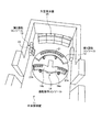
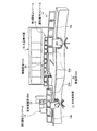
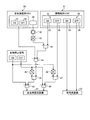
図1は、本発明の一実施例に係る原子力プラントの運転監視装置における中央制御室を表す概略図、図2は、本実施例の原子力プラントの運転監視装置における機能統合VDU及び安全保護系VDUを表す概略図、図3は、本実施例の原子力プラントの運転監視装置における制御ブロックを表す概略図である。 FIG. 1 is a schematic diagram showing a central control room in an operation monitoring apparatus for a nuclear power plant according to one embodiment of the present invention, and FIG. 2 is a function integrated VDU and safety protection system VDU in the operation monitoring apparatus for a nuclear power plant according to the present embodiment. FIG. 3 is a schematic diagram illustrating a control block in the operation monitoring apparatus for the nuclear power plant according to the present embodiment.
本実施例の原子力プラントの運転監視装置において、図1及び図2に示すように、中央制御室11は、ほぼ密閉された部屋であり、第1運転コンソール12、第2運転コンソール13、運転指令コンソール14、大型表示盤15が配置されている。この場合、最前部に大型表示盤15が配置され、この大型表示盤15の前面に対向して第1運転コンソール12がこの大型表示盤15に向って配置されている。また、第1運転コンソール12に隣接して、中央制御室11の壁面に第2運転コンソール13が配置されている。そして、大型表示盤15の前面に対向し、且つ、第1運転コンソール12の後方に運転指令コンソール14が大型表示盤15に向って配置されている。
In the operation monitoring apparatus of the nuclear power plant of this embodiment, as shown in FIGS. 1 and 2, the
即ち、中央制御室11は、その中央に第1運転コンソール12及び運転指令コンソール14が配置され、第1運転コンソール12に隣接して中央制御室11の壁面近傍に第2運転コンソール13が配置されている。具体的に、運転指令コンソール14は、中央制御室11の中央部に描かれる円のほぼ中心部に配置され、第1運転コンソール12は、その円における大型表示盤15側に円弧をなすように配置されている。第2運転コンソール13は、この円の外側に、中央制御室11の壁面に密着して配置されている。
That is, the
そして、第1運転コンソール12は、機能統合VDU21が搭載され、第2運転コンソール13は、安全保護系VDU22が搭載されている。この機能統合VDU21は、プラントの正常時にこのプラントを運転監視する常用系制御機能と、プラントの異常時にこのプラントを安全に停止する(安全状態へと導く)安全保護系制御機能を有している。一方、安全保護系VDU22は、機能統合VDU21における安全保護系制御機能のバックアップ用のVDUであり、プラントの異常時にこのプラントを安全に停止する(安全状態へと導く)安全保護系制御機能を有している。なお、VDUとは、Visual Display Unitである。
The
また、第1運転コンソール12(機能統合VDU21)及び第2運転コンソール13(安全保護系VDU22)は、運転員が操作するものである。一方、運転指令コンソール14は、運転員に指令を出す当直長が操作するものであり、管理用VDU23が搭載されている。本実施例では、運転指令コンソール14は、監督指令コンソール14a(監督用VDU23a)と、技術指令コンソール14b(技術者用VDU23b)とから構成されている。
The first operation console 12 (function integrated VDU 21) and the second operation console 13 (safety protection system VDU 22) are operated by the operator. On the other hand, the
この場合、安全保護系VDU22が搭載された第2運転コンソール13は、耐震性の優れた構造とするために、硬質な鉄板により被覆する構造となっている。一方、常用系制御機能と安全保護系制御機能を有する機能統合VDU21が搭載された第1運転コンソール12は、一般的な耐震性を有する構造とすればよく、硬質な鉄板により被覆する構造とする必要はない。
In this case, the
なお、本実施例の原子力プラントの運転監視装置における中央制御室11にて、機能統合VDU21の異常時に、この機能統合VDU21による安全保護系制御機能の作動を阻止(作動の阻害)するブロック装置が設けられている。ここでは、このブロック装置は、第2運転コンソール13(安全保護系VDU22)に設けられている。
In the
このブロック装置は、機能統合VDU21から出力されるプラント停止信号(プラント操作信号)と、安全保護系VDU22から出力されるブロック信号とが入力するアンド回路(ソフトウェア)により構成されている。この場合、機能統合VDU21及び安全保護系VDU22から出力されるプラント停止信号、安全保護系VDU22から出力されるブロック信号は、運転員の操作により出力される手動信号である。そして、機能統合VDU21及び安全保護系VDU22から出力されるプラント手動停止信号と、プラントのプロセス量に基づいて出力されるプラント自動停止信号とのいずれかが出力されたときに原子力プラントを停止させる。
This block device is configured by an AND circuit (software) to which a plant stop signal (plant operation signal) output from the
即ち、図3に示すように、機能統合VDU21は、安全保護系VDU31の機能と常用系(非安全保護系)VDU32の機能を有している。即ち、安全保護系VDU31としては、安全保護系設備51における各種機器を作動停止するON操作スイッチ33とOFF操作スイッチ34とが設けられている。常用系VDU32として、常用系設備52における各種機器を作動停止するON操作スイッチ35とOFF操作スイッチ36とが設けられている。この場合、安全保護系VDU31における各操作スイッチ33,34、常用系VDU32における各操作スイッチ35,36は、ここではそれぞれ1つを例示したが、実際には、各種機器に応じて複数設けられている。
That is, as shown in FIG. 3, the
安全保護系VDU22は、安全保護系設備51における各種機器を作動停止するON操作スイッチ37とOFF操作スイッチ38とを有すると共に、ブロック装置を作動させる切断操作スイッチ39とを有している。この場合、安全保護系VDU22における各操作スイッチ37,38,39は、ここではそれぞれ1つを例示したが、実際には、各種機器に応じて複数設けられている。
The safety
安全保護系VDU31のON操作スイッチ33の信号は、アンド(AND)回路41に入力する。また、安全保護系VDU22の切断操作スイッチ39の信号は、ラッチ回路42及びノット(NOT)回路43を介してアンド回路41に入力する。この場合、安全保護系VDU22の切断操作スイッチ39が操作されていないとき、ON信号「0」がノット回路43で反転してON信号「1」としてアンド回路41に入力しており、安全保護系VDU31のON操作スイッチ33が操作されてON信号「1」がアンド回路41に入力されると、このアンド回路41はON信号「1」を出力する。
A signal from the ON operation switch 33 of the safety
アンド回路41から出力された信号はオア(OR)回路44に入力する。また、安全保護系VDU22のON操作スイッチ37とOFF操作スイッチ38から出力された信号はオア(OR)回路44に入力する。この場合、アンド回路41からON信号「1」、または、ON操作スイッチ37からON信号「1」がオア回路44に入力されると、このオア回路44はON信号「1」を出力する。なお、この安全保護系VDU22では、ON操作スイッチ37が操作されるとON信号「1」が出力され、OFF操作スイッチ38が操作されたとき、どちらのスイッチも操作されないときにON信号「0」、つまり、OFF信号「1」が出力されるものとして説明する。
The signal output from the AND
一方、安全保護系VDU22の切断操作スイッチ39が操作されたとき、ON信号「1」がノット回路43で反転してON信号「0」としてアンド回路41に入力しており、安全保護系VDU31のON操作スイッチ33が操作されてON信号「1」がアンド回路41に入力されても、このアンド回路41はON信号「1」を出力しない。即ち、機能統合VDU21の安全保護系VDU31と安全保護系VDU22とでは、安全保護系VDU22の処理が優先されるようになっている。
On the other hand, when the
上述した機能統合VDU21における安全保護系VDU31の各操作スイッチ33,34、常用系VDU32の各操作スイッチ35,36、安全保護系VDU22における各操作スイッチ37,38,39は、運転員が手動により操作するものであり、運転員が安全保護系設備51に異常が発生したことを発見したときに、手動停止信号を出力することでこの安全保護系設備51を安全に停止させるようにしている。
The operation switches 33 and 34 of the safety
一方、原子力プラントでは、各種機器の状態を検出する多数のセンサが設けられており、図示しない制御装置は、この各センサの検出結果に基づいて運転状態を監視している。そして、制御装置が安全保護系設備51に異常が発生したことを検出したときに、自動停止信号を出力することでこの安全保護系設備51を安全に停止させるようにしている。
On the other hand, in a nuclear power plant, a large number of sensors for detecting the state of various devices are provided, and a control device (not shown) monitors the operating state based on the detection result of each sensor. When the control device detects that an abnormality has occurred in the safety
この自動停止のON信号は、オア回路45に入力すると共に、ノット回路46を介してアンド回路47に入力する。また、自動停止のOFF信号は、オア回路48に入力すると共に、ノット回路49を介してアンド回路50に入力する。そして、アンド回路50から出力された信号はオア回路45に入力する一方、OFF操作スイッチ34から出力された信号はアンド回路47を介してオア回路48に入力する。
The automatic stop ON signal is input to the
この場合、制御装置が自動停止のON信号を出力していれば、ON信号「1」がオア回路45に入力し、機能統合VDU21や安全保護系VDU22からの信号にかかわらず、オア回路45は、安全保護系設備51を停止させるための自動停止ON信号「1」を出力する。また、運転員の操作により機能統合VDU21や安全保護系VDU22から手動停止のON信号が出力されていれば、ON信号「1」がオア回路45に入力し、自動停止のON信号にかかわらず、オア回路45は、安全保護系設備51を停止させるための自動停止ON信号「1」を出力する。
In this case, if the control device outputs an automatic stop ON signal, the ON signal “1” is input to the
一方、制御装置が自動停止のON信号を出力していなければ、ON信号「0」がオア回路45に入力する。また、運転員が操作せずに、機能統合VDU21や安全保護系VDU22から手動停止のON信号が出力されていなければ、ON信号「0」がオア回路45に入力する。そのため、オア回路45は、安全保護系設備51を停止させるための自動停止ON信号「1」を出力することはない。
On the other hand, if the control device does not output the automatic stop ON signal, the ON signal “0” is input to the
また、制御装置が自動停止のOFF信号を出力していれば、OFF信号「1」がオア回路48に入力し、機能統合VDU21や安全保護系VDU22からの信号にかかわらず、オア回路48は、安全保護系設備51を停止させないための自動停止OFF信号「1」を出力する。また、運転員の操作により機能統合VDU21や安全保護系VDU22から安全保護系設備51を停止させないための手動停止のOFF信号「1」が出力されていれば、OFF信号「1」がオア回路48に入力し、自動停止のOFF信号にかかわらず、オア回路48は、安全保護系設備51を停止させないための自動停止OFF信号「1」を出力する。
Further, if the control device outputs an automatic stop OFF signal, the OFF signal “1” is input to the
一方、制御装置が自動停止のOFF信号を出力していなければ、OFF信号「0」がオア回路48に入力する。また、運転員が操作せずに、機能統合VDU21や安全保護系VDU22から手動停止のON信号が出力されていなければ、ON信号「0」がオア回路45に入力する。そのため、オア回路48は、安全保護系設備51を停止させるための自動停止ON信号「1」を出力することはない。
On the other hand, if the control device does not output the automatic stop OFF signal, the OFF signal “0” is input to the
更に、自動停止のON信号「1」が出力されていれば、このON信号「1」がノット回路46で反転されてON信号「0」となり、アンド回路47に入力することから、運転員がOFF操作スイッチ34を操作して手動停止のOFF信号「1」を出力しても、アンド回路47は、OFF信号「1」を出力しない。即ち、自動停止のON信号「1」が出力されていれば、機能統合VDU21の安全保護系VDU31や安全保護系VDU22からの手動停止のOFF信号「1」より、自動停止のON信号「1」の処理が優先されるようになっている。なお、自動停止のON信号「1」が出力されていなければ、ON信号「0」がノット回路46で反転されてON信号「1」となり、アンド回路47に入力することから、運転員がOFF操作スイッチ34を操作して手動停止のOFF信号「1」を出力すると、アンド回路47は、OFF信号「1」を出力することができる。
Further, if the automatic stop ON signal “1” is output, the ON signal “1” is inverted by the
一方、自動停止のOFF信号「1」が出力されていれば、このOFF信号「1」がノット回路49で反転されてON信号「0」となり、アンド回路50に入力することから、運転員がON操作スイッチ33を操作して手動停止のON信号「1」を出力しても、アンド回路47は、ON信号「1」を出力しない。即ち、自動停止のOFF信号「1」が出力されていれば、機能統合VDU21の安全保護系VDU31や安全保護系VDU22からの手動停止のON信号「1」より、自動停止のOFF信号「1」の処理が優先されるようになっている。なお、自動停止のOFF信号「1」が出力されていなければ、OFF信号「0」がノット回路49で反転されてON信号「1」となり、アンド回路50に入力することから、運転員がON操作スイッチ33を操作して手動停止のON信号「1」を出力すると、オア回路11を介してアンド回路50に入力し、このアンド回路50はON信号「1」を出力することができる。
On the other hand, if the automatic stop OFF signal “1” is output, the OFF signal “1” is inverted by the
なお、機能統合VDU21の常用系VDU32にて、運転員がON操作スイッチ35やOFF操作スイッチ36を操作すると、手動停止のON信号「1」や手動停止のOFF信号「1」が常用系設備52に対して出力される。
When an operator operates the
本実施例にて、ブロック装置は、上述したように、機能統合VDU21の安全保護系VDU31から出力されるプラント停止信号(自動停止のON信号「1」)と、安全保護系VDU22の切断操作スイッチ39から出力されるブロック信号(ON信号「1」)とが入力するアンド回路41により構成されている。
In this embodiment, as described above, the block device includes a plant stop signal (automatic stop ON signal “1”) output from the safety
ここで、本実施例の原子力プラントの運転監視装置における機能統合VDU21及び安全保護系VDU22の作用について説明する。
Here, the operation of the function integrated
通常、運転員は、機能統合VDU21を用いて原子力プラントの運転監視を行っている。そして、プラントの運転状態により異常を発見し、必要な操作が安全保護系VDU31であった場合、安全保護系設備51の機器に異常を発見すると、安全保護系VDU31のON操作スイッチ33を操作して手動停止のON信号「1」を出力する。すると、ON操作スイッチ33から出力された手動停止のON信号「1」は、アンド回路41に入力する。このとき、機能統合VDU21の安全保護系VDU31が正常に作動していることから、安全保護系VDU22の切断操作スイッチ39は操作されておらず、ON信号「0」がノット回路43で反転してON信号「1」としてアンド回路41に入力している。そのため、アンド回路41はON信号「1」を出力する。
Usually, the operator performs operation monitoring of the nuclear power plant using the function integrated
オア回路44は、アンド回路41から入力したON信号「1」を出力する。アンド回路50では、自動停止のOFF信号が出力されていないことから、OFF信号「0」がノット回路49で反転されてOFF信号「1」となってアンド回路50に入力し、アンド回路50はON信号「1」を出力し、この手動停止のON信号「1」がオア回路45を介して安全保護系設備51に入力され、これを安全に停止する。
The OR
そして、運転員は、機能統合VDU21の安全保護系VDU31に異常を発見したときには、この安全保護系VDU31による操作を不能とし、安全保護系VDU22による操作を行う。即ち、運転員が安全保護系VDU31に異常を発見したとき、安全保護系VDU22の切断操作スイッチ39を操作する。すると、ON信号「1」がノット回路43で反転してON信号「0」としてアンド回路41に入力する。そのため、運転者が安全保護系VDU31のON操作スイッチ33を操作して手動停止のON信号「1」を出力し、この手動停止のON信号「1」をアンド回路41に入力しても、安全保護系VDU22の切断操作スイッチ39からON信号「0」が入力していることから、アンド回路41が手動停止のON信号「1」を出力することはない。
When the operator finds an abnormality in the safety
運転員は、機能統合VDU21の安全保護系VDU31が故障して操作できないことから、安全保護系VDU22のON操作スイッチ37を操作して手動停止のON信号「1」を出力する。すると、ON操作スイッチ37から出力された手動停止のON信号「1」は、オア回路44に出力され、そのON信号「1」を出力する。アンド回路50では、前述したように、自動停止のOFF信号「1」が入力していることから、ON信号「1」を出力し、この手動停止のON信号「1」がオア回路45を介して安全保護系設備31に入力され、これを安全に停止する。
The operator outputs the manual stop ON signal “1” by operating the ON operation switch 37 of the safety
このように本実施例の原子力プラントの運転監視装置にあっては、正常時の原子力プラントを運転監視する常用系VDU32と異常時の原子力プラントを停止する安全保護系VDU31を有する機能統合VDU21を設けると共に、異常時の原子力プラントを停止させる安全保護系VDU22とを設け、機能統合VDU21を第1運転コンソール12に搭載し、安全保護系VDU22を第2運転コンソール13に搭載している。
As described above, in the operation monitoring apparatus for the nuclear power plant according to the present embodiment, the function integrated
従って、安全保護系VDU31及び常用系VDU32を有する機能統合VDU21を第1運転コンソール12に搭載し、安全保護系VDU22を第2運転コンソール13に搭載し、安全保護系VDU31のバックアップとして用いている。そのため、第2運転コンソール13だけを耐震性の優れた構造とし、第1運転コンソール12を一般的な耐震性を有する構造とすればよく、耐震補強による第1運転コンソール12の大型化を抑制し、運転操作の容易化を可能とすることができる。
Therefore, the function integrated
また、本実施例の原子力プラントの運転監視装置では、中央制御室11の中央に第1運転コンソール12を配置し、第1運転コンソール12に隣接して中央制御室11の壁面近傍に第2運転コンソール13を配置している。従って、各運転コンソール12,13を適正配置とすることで、中央制御室11内の空間の有効利用を図ることができる。
In the operation monitoring apparatus for a nuclear power plant according to the present embodiment, the
即ち、第1運転コンソール12の大型化が抑制されることで、中央制御室11における各種機器の配置が容易となり、通路スペースを容易に確保することができ、作業性を向上することができ、また、その他の機器を適正に配置することができる。
That is, since the enlargement of the
また、本実施例の原子力プラントの運転監視装置では、正常時の原子力プラントを運転監視する常用系VDU32と異常時の原子力プラントを停止する安全保護系VDU31を有する機能統合VDU21を設けると共に、異常時の原子力プラントを停止させる安全保護系VDU22とを設け、機能統合VDU21の異常時に安全保護系VDU31の作動を阻止するブロック装置を設けている。
In addition, in the operation monitoring apparatus for a nuclear power plant according to the present embodiment, a function integrated
従って、機能統合VDU21の正常時には、この機能統合VDU21の安全保護系VDU31を用いて異常時の原子力プラントを安全に停止させる一方、この機能統合VDU21の異常時には、ブロック装置により、機能統合VDU21における安全保護系VDU31の作動を阻止し、安全保護系VDU22を用いて異常時の原子力プラントを停止させることとなる。この場合、機能統合VDU21により、正常時の原子力プラント制御と異常時のプラント停止を実行することが可能となり、原子力プラントにおける運転操作の容易化を可能とすることができる。また、機能統合VDU21の異常時には、ブロック装置により、機能統合VDU21による安全保護系VDU31の作動を阻止し、バックアップとなる安全保護系VDU22を用いて異常時の原子力プラントを停止することとなり、異常時のプラント停止を確実に行うことができ、運転制御の高い安全性を確保することができる。
Therefore, when the function integrated
また、本実施例の原子力プラントの運転監視装置では、ブロック装置を安全保護系VDU22に設けている。従って、ブロック装置により、機能統合VDU21における安全保護系VDU31の作動を阻止した後、直ちに、安全保護系VDU22を用いて異常時の原子力プラントを停止することができる。 In the nuclear power plant operation monitoring apparatus of this embodiment, the block device is provided in the safety protection system VDU22. Therefore, the nuclear power plant at the time of abnormality can be stopped immediately using the safety protection system VDU22 after blocking | blocking the action | operation of the safety protection system VDU31 in the function integrated VDU21 by a block apparatus.
また、本実施例の原子力プラントの運転監視装置では、ブロック装置を、機能統合VDU21の安全保護系VDU31から出力されるプラント停止信号と、安全保護系VDU22から出力されるブロック信号とが入力するアンド回路41により構成している。従って、ブロック装置を論理回路により構成することで、装置の簡素化を可能とすることができる。
Further, in the operation monitoring apparatus for a nuclear power plant of this embodiment, the block device is an AND that receives the plant stop signal output from the safety protection system VDU31 of the
なお、上述した実施例にて、第1運転コンソール12、第2運転コンソール13、運転指令コンソール14、大型表示盤15の配置は、説明した配置に限定されるものではなく、中央制御室11の広さや形、また、別の機器との関係により適宜設定すればよいものである。
In addition, in the Example mentioned above, arrangement | positioning of the
本発明に係る原子力プラントの運転監視装置は、常用系制御機能及び安全保護系制御機能を有する第1運転コンソールと安全保護系制御機能を有する第2運転コンソールを設けることで、原子力プラントにおける運転コンソールの大型化を抑制して運転操作の容易化を可能とするものであり、いずれの原子力プラントにも適用することができる。 An operation monitoring apparatus for a nuclear power plant according to the present invention is provided with a first operation console having a regular system control function and a safety protection system control function and a second operation console having a safety protection system control function, so that the operation console in the nuclear power plant is provided. This makes it possible to facilitate the operation operation by suppressing the increase in size, and can be applied to any nuclear power plant.
11 中央制御室
12 第1運転コンソール
13 第2運転コンソール
14 運転指令コンソール
15 大型表示盤
21 機能統合VDU
22 安全保護系VDU
31 安全保護系VDU
32 常用系(非安全保護系)VDU
39 切断操作スイッチ(ブロック装置)
41 アンド回路(ブロック装置)
42 ラッチ回路(ブロック装置)
43 ノット回路(ブロック装置)
44 オア回路
45 オア回路
46 ノット回路
47 アンド回路
48 オア回路
49 ノット回路
50 アンド回路
51 安全保護系設備
52 常用系設備
11
22 Safety protection system VDU
31 Safety protection system VDU
32 Regular (non-safety protection) VDU
39 Cutting operation switch (block device)
41 AND circuit (block device)
42 Latch circuit (block device)
43 knot circuit (block device)
44 OR
Claims (3)
異常時のプラントを安全状態へと導く安全保護系制御機能を有する第2運転コンソールと、
を備えることを特徴とする原子力プラントの運転監視装置。 A first operation console having a normal system control function for monitoring the operation of the plant in a normal state and a safety protection system control function for guiding the plant in an abnormal state to a safe state;
A second operation console having a safety protection system control function for guiding the plant in an abnormal state to a safe state;
An operation monitoring device for a nuclear power plant comprising:
3. The nuclear power plant according to claim 1, further comprising: a block device that blocks the operation of the safety protection system control function by the first operation console when the safety protection system control function of the first operation console is abnormal. Operation monitoring device.
Priority Applications (4)
| Application Number | Priority Date | Filing Date | Title |
|---|---|---|---|
| JP2010249090A JP5798736B2 (en) | 2010-11-05 | 2010-11-05 | Nuclear power plant operation monitoring device |
| PCT/JP2011/074351 WO2012060233A1 (en) | 2010-11-05 | 2011-10-21 | Device for monitoring operation of nuclear power plant |
| EP11837884.3A EP2637174B1 (en) | 2010-11-05 | 2011-10-21 | Device for monitoring operation of nuclear power plant |
| US13/876,751 US9436167B2 (en) | 2010-11-05 | 2011-10-21 | Device for monitoring operation of nuclear plant |
Applications Claiming Priority (1)
| Application Number | Priority Date | Filing Date | Title |
|---|---|---|---|
| JP2010249090A JP5798736B2 (en) | 2010-11-05 | 2010-11-05 | Nuclear power plant operation monitoring device |
Publications (2)
| Publication Number | Publication Date |
|---|---|
| JP2012103013A true JP2012103013A (en) | 2012-05-31 |
| JP5798736B2 JP5798736B2 (en) | 2015-10-21 |
Family
ID=46024350
Family Applications (1)
| Application Number | Title | Priority Date | Filing Date |
|---|---|---|---|
| JP2010249090A Active JP5798736B2 (en) | 2010-11-05 | 2010-11-05 | Nuclear power plant operation monitoring device |
Country Status (4)
| Country | Link |
|---|---|
| US (1) | US9436167B2 (en) |
| EP (1) | EP2637174B1 (en) |
| JP (1) | JP5798736B2 (en) |
| WO (1) | WO2012060233A1 (en) |
Cited By (3)
| Publication number | Priority date | Publication date | Assignee | Title |
|---|---|---|---|---|
| JP2018190081A (en) * | 2017-04-28 | 2018-11-29 | 三菱重工業株式会社 | Monitoring control device of plant |
| WO2023144857A1 (en) * | 2022-01-25 | 2023-08-03 | 三菱電機株式会社 | Monitoring and controlling system |
| JP7357829B1 (en) * | 2023-03-10 | 2023-10-06 | 三菱電機株式会社 | plant control system |
Families Citing this family (3)
| Publication number | Priority date | Publication date | Assignee | Title |
|---|---|---|---|---|
| CN103337266A (en) * | 2013-05-27 | 2013-10-02 | 中国核电工程有限公司 | Back-up disk function analytic method of nuclear power plant using digital man-machine interface |
| JPWO2024018578A1 (en) * | 2022-07-21 | 2024-01-25 | ||
| CN116779201A (en) * | 2023-05-16 | 2023-09-19 | 中国核电工程有限公司 | Nuclear power plant instrumentation and control system and method for intelligent operation and maintenance and its nuclear power plant |
Citations (5)
| Publication number | Priority date | Publication date | Assignee | Title |
|---|---|---|---|---|
| JPH02244396A (en) * | 1989-03-17 | 1990-09-28 | Toshiba Corp | Plant monitor and control equipment |
| JP2003207591A (en) * | 2002-01-15 | 2003-07-25 | Hitachi Ltd | Reactor control rod position monitoring system |
| JP2005114516A (en) * | 2003-10-07 | 2005-04-28 | Toshiba Corp | Information providing apparatus and information providing method for nuclear power plant |
| JP2007041982A (en) * | 2005-08-05 | 2007-02-15 | Toshiba Corp | Plant warning system and plant warning method |
| JP2008115661A (en) * | 2006-11-08 | 2008-05-22 | Chugoku Electric Power Co Inc:The | Central control room of power plant |
Family Cites Families (8)
| Publication number | Priority date | Publication date | Assignee | Title |
|---|---|---|---|---|
| US4421716A (en) * | 1980-12-29 | 1983-12-20 | S. Levy, Inc. | Safety monitoring and reactor transient interpreter |
| US4786462A (en) * | 1984-02-21 | 1988-11-22 | Stone & Webster Engineering Corp. | Support structure for a nuclear reactor |
| JP2947840B2 (en) | 1989-12-22 | 1999-09-13 | 株式会社日立製作所 | Plant operation monitoring device |
| JP4568143B2 (en) * | 2005-02-28 | 2010-10-27 | 株式会社東芝 | Safety system verification method and safety system verified by the verification method |
| JP4758759B2 (en) * | 2005-12-27 | 2011-08-31 | 株式会社ミツトヨ | Earthquake disaster prevention system |
| JP5054654B2 (en) * | 2008-10-24 | 2012-10-24 | 三菱電機株式会社 | Plant operation device |
| JP5185864B2 (en) * | 2009-03-25 | 2013-04-17 | 三菱電機株式会社 | Safety operation equipment for nuclear power plants |
| JP2012013581A (en) * | 2010-07-01 | 2012-01-19 | Mitsubishi Heavy Ind Ltd | Operation monitoring device of nuclear power plant |
-
2010
- 2010-11-05 JP JP2010249090A patent/JP5798736B2/en active Active
-
2011
- 2011-10-21 EP EP11837884.3A patent/EP2637174B1/en active Active
- 2011-10-21 US US13/876,751 patent/US9436167B2/en active Active
- 2011-10-21 WO PCT/JP2011/074351 patent/WO2012060233A1/en not_active Ceased
Patent Citations (5)
| Publication number | Priority date | Publication date | Assignee | Title |
|---|---|---|---|---|
| JPH02244396A (en) * | 1989-03-17 | 1990-09-28 | Toshiba Corp | Plant monitor and control equipment |
| JP2003207591A (en) * | 2002-01-15 | 2003-07-25 | Hitachi Ltd | Reactor control rod position monitoring system |
| JP2005114516A (en) * | 2003-10-07 | 2005-04-28 | Toshiba Corp | Information providing apparatus and information providing method for nuclear power plant |
| JP2007041982A (en) * | 2005-08-05 | 2007-02-15 | Toshiba Corp | Plant warning system and plant warning method |
| JP2008115661A (en) * | 2006-11-08 | 2008-05-22 | Chugoku Electric Power Co Inc:The | Central control room of power plant |
Cited By (6)
| Publication number | Priority date | Publication date | Assignee | Title |
|---|---|---|---|---|
| JP2018190081A (en) * | 2017-04-28 | 2018-11-29 | 三菱重工業株式会社 | Monitoring control device of plant |
| WO2023144857A1 (en) * | 2022-01-25 | 2023-08-03 | 三菱電機株式会社 | Monitoring and controlling system |
| JPWO2023144857A1 (en) * | 2022-01-25 | 2023-08-03 | ||
| JP7527509B2 (en) | 2022-01-25 | 2024-08-02 | 三菱電機株式会社 | Supervisory Control System |
| JP7357829B1 (en) * | 2023-03-10 | 2023-10-06 | 三菱電機株式会社 | plant control system |
| WO2024189668A1 (en) * | 2023-03-10 | 2024-09-19 | 三菱電機株式会社 | Plant control system |
Also Published As
| Publication number | Publication date |
|---|---|
| US20130245848A1 (en) | 2013-09-19 |
| JP5798736B2 (en) | 2015-10-21 |
| EP2637174B1 (en) | 2018-08-01 |
| EP2637174A4 (en) | 2017-07-26 |
| US9436167B2 (en) | 2016-09-06 |
| WO2012060233A1 (en) | 2012-05-10 |
| EP2637174A1 (en) | 2013-09-11 |
Similar Documents
| Publication | Publication Date | Title |
|---|---|---|
| JP5660833B2 (en) | Nuclear power plant operation monitoring device | |
| JP5798736B2 (en) | Nuclear power plant operation monitoring device | |
| KR101790860B1 (en) | Display device of working vehicle, display method of the same, and working vehicle | |
| JP5631098B2 (en) | Nuclear power plant operation monitoring device | |
| US20130119784A1 (en) | Emergency stop system for a hybrid excavator | |
| CN108711459A (en) | A kind of diversified protective device for fast reactor | |
| CN101723218B (en) | elevator control device | |
| JP6948865B2 (en) | Passenger conveyor alarm system | |
| US20130044848A1 (en) | Operation monitoring apparatus of nuclear power plant | |
| JP5633782B2 (en) | Elevating type multilevel parking system | |
| CN107851974B (en) | Disconnection control method and power conversion device using the same | |
| JP4784949B2 (en) | Elevator operation control device | |
| CN103543705A (en) | Implementation method for switching operational state of mainframe | |
| JP2013195397A (en) | Nuclear power plant control system and alternative monitoring and control method thereof | |
| KR101168021B1 (en) | Alarm method and system for abnormalty of ship and ship having the system | |
| GB2531679A (en) | Auxiliary control method for nuclear power plant operation, and device and system therefor | |
| WO2012112034A2 (en) | A device, system and method for activation of a plurality of fire extinguishing devices | |
| CN110844036A (en) | Layout structure of the main control room of a nuclear powered ship | |
| JP6470067B2 (en) | Inverter device and program for inverter device | |
| JP2007041982A (en) | Plant warning system and plant warning method | |
| JP2002059167A5 (en) | ||
| CN120540230A (en) | Safety protection device and protection method for reverse osmosis system | |
| JP2012056707A (en) | Maintenance system for elevator | |
| JP2004110226A (en) | Emergency stop operation system | |
| JPH022403A (en) | Plant state display device |
Legal Events
| Date | Code | Title | Description |
|---|---|---|---|
| A621 | Written request for application examination |
Free format text: JAPANESE INTERMEDIATE CODE: A621 Effective date: 20131029 |
|
| A131 | Notification of reasons for refusal |
Free format text: JAPANESE INTERMEDIATE CODE: A131 Effective date: 20140826 |
|
| A02 | Decision of refusal |
Free format text: JAPANESE INTERMEDIATE CODE: A02 Effective date: 20150317 |
|
| A521 | Written amendment |
Free format text: JAPANESE INTERMEDIATE CODE: A523 Effective date: 20150608 |
|
| A911 | Transfer of reconsideration by examiner before appeal (zenchi) |
Free format text: JAPANESE INTERMEDIATE CODE: A911 Effective date: 20150615 |
|
| TRDD | Decision of grant or rejection written | ||
| A01 | Written decision to grant a patent or to grant a registration (utility model) |
Free format text: JAPANESE INTERMEDIATE CODE: A01 Effective date: 20150728 |
|
| A61 | First payment of annual fees (during grant procedure) |
Free format text: JAPANESE INTERMEDIATE CODE: A61 Effective date: 20150824 |
|
| R151 | Written notification of patent or utility model registration |
Ref document number: 5798736 Country of ref document: JP Free format text: JAPANESE INTERMEDIATE CODE: R151 |