JP2012103545A - Developing device, image forming apparatus and method for forming image - Google Patents
Developing device, image forming apparatus and method for forming image Download PDFInfo
- Publication number
- JP2012103545A JP2012103545A JP2010252854A JP2010252854A JP2012103545A JP 2012103545 A JP2012103545 A JP 2012103545A JP 2010252854 A JP2010252854 A JP 2010252854A JP 2010252854 A JP2010252854 A JP 2010252854A JP 2012103545 A JP2012103545 A JP 2012103545A
- Authority
- JP
- Japan
- Prior art keywords
- potential
- developer
- liquid developer
- liquid
- developing
- Prior art date
- Legal status (The legal status is an assumption and is not a legal conclusion. Google has not performed a legal analysis and makes no representation as to the accuracy of the status listed.)
- Pending
Links
- 238000000034 method Methods 0.000 title claims description 17
- 239000007788 liquid Substances 0.000 claims abstract description 148
- 238000005259 measurement Methods 0.000 claims abstract description 19
- 238000004140 cleaning Methods 0.000 claims description 29
- 238000001514 detection method Methods 0.000 claims description 26
- 238000011161 development Methods 0.000 claims description 14
- 238000012546 transfer Methods 0.000 description 60
- 238000007774 anilox coating Methods 0.000 description 15
- 239000010410 layer Substances 0.000 description 15
- 239000000463 material Substances 0.000 description 13
- 238000010586 diagram Methods 0.000 description 11
- 108091008695 photoreceptors Proteins 0.000 description 11
- 239000002245 particle Substances 0.000 description 10
- 239000000049 pigment Substances 0.000 description 10
- 230000008569 process Effects 0.000 description 8
- 238000007639 printing Methods 0.000 description 6
- 239000003086 colorant Substances 0.000 description 5
- 238000011084 recovery Methods 0.000 description 5
- 239000007787 solid Substances 0.000 description 5
- 239000002184 metal Substances 0.000 description 4
- 229910052751 metal Inorganic materials 0.000 description 4
- 229910052799 carbon Inorganic materials 0.000 description 3
- 125000003367 polycyclic group Chemical group 0.000 description 3
- 239000002344 surface layer Substances 0.000 description 3
- XEEYBQQBJWHFJM-UHFFFAOYSA-N Iron Chemical compound [Fe] XEEYBQQBJWHFJM-UHFFFAOYSA-N 0.000 description 2
- 239000003795 chemical substances by application Substances 0.000 description 2
- 230000006835 compression Effects 0.000 description 2
- 238000007906 compression Methods 0.000 description 2
- 230000001276 controlling effect Effects 0.000 description 2
- 239000002270 dispersing agent Substances 0.000 description 2
- 239000008157 edible vegetable oil Substances 0.000 description 2
- 230000000694 effects Effects 0.000 description 2
- 230000005684 electric field Effects 0.000 description 2
- 230000002349 favourable effect Effects 0.000 description 2
- 239000010408 film Substances 0.000 description 2
- 239000002480 mineral oil Substances 0.000 description 2
- 235000010446 mineral oil Nutrition 0.000 description 2
- 238000012545 processing Methods 0.000 description 2
- 230000001105 regulatory effect Effects 0.000 description 2
- 229920002545 silicone oil Polymers 0.000 description 2
- 239000002904 solvent Substances 0.000 description 2
- 230000007704 transition Effects 0.000 description 2
- 238000011144 upstream manufacturing Methods 0.000 description 2
- 229920000459 Nitrile rubber Polymers 0.000 description 1
- 239000004642 Polyimide Substances 0.000 description 1
- 229920006311 Urethane elastomer Polymers 0.000 description 1
- 230000009471 action Effects 0.000 description 1
- 238000013019 agitation Methods 0.000 description 1
- 229910021417 amorphous silicon Inorganic materials 0.000 description 1
- 239000002199 base oil Substances 0.000 description 1
- 239000006229 carbon black Substances 0.000 description 1
- 230000008859 change Effects 0.000 description 1
- 239000011248 coating agent Substances 0.000 description 1
- 238000000576 coating method Methods 0.000 description 1
- 238000010292 electrical insulation Methods 0.000 description 1
- 230000008030 elimination Effects 0.000 description 1
- 238000003379 elimination reaction Methods 0.000 description 1
- 239000004744 fabric Substances 0.000 description 1
- 239000001023 inorganic pigment Substances 0.000 description 1
- 238000009413 insulation Methods 0.000 description 1
- 229910052742 iron Inorganic materials 0.000 description 1
- 150000002894 organic compounds Chemical class 0.000 description 1
- 239000003960 organic solvent Substances 0.000 description 1
- 238000005192 partition Methods 0.000 description 1
- 229920011301 perfluoro alkoxyl alkane Polymers 0.000 description 1
- 230000002093 peripheral effect Effects 0.000 description 1
- 229920001721 polyimide Polymers 0.000 description 1
- 229920002635 polyurethane Polymers 0.000 description 1
- 239000004814 polyurethane Substances 0.000 description 1
- 229920003225 polyurethane elastomer Polymers 0.000 description 1
- 239000000843 powder Substances 0.000 description 1
- 239000011347 resin Substances 0.000 description 1
- 229920005989 resin Polymers 0.000 description 1
- 238000007790 scraping Methods 0.000 description 1
- 229920002379 silicone rubber Polymers 0.000 description 1
- 230000003068 static effect Effects 0.000 description 1
- 229920005992 thermoplastic resin Polymers 0.000 description 1
- 239000010409 thin film Substances 0.000 description 1
Images





Landscapes
- Developing For Electrophotography (AREA)
- Wet Developing In Electrophotography (AREA)
Abstract
【課題】現像剤担持体に担持された液体現像剤を好適な帯電状態に調整する。
【解決手段】本発明に係る現像装置は、トナー及びキャリア液を含む液体現像剤を担持するとともに現像バイアスが印加される現像剤担持体20と、現像剤担持体20に担持された液体現像剤を帯電させる帯電部22と、液体現像剤が担持されていない位置での現像剤担持体20の電位である第1の電位と、液体現像剤が担持されて帯電部22で帯電される位置での現像剤担持体20の電位である第2の電位とを測定する電位測定部23と、電位測定部23で測定された第1の電位と第2の電位の差分を算出し、算出された差分に基づいて液体現像剤への帯電を調整する制御部と、を有することを特徴としている。
【選択図】図5A liquid developer carried on a developer carrying member is adjusted to a suitable charged state.
A developing device according to the present invention includes a developer carrying body that carries a liquid developer containing toner and a carrier liquid and is applied with a developing bias, and a liquid developer carried on the developer carrying body. The charging unit 22 for charging the first developer, the first potential which is the potential of the developer carrier 20 at a position where the liquid developer is not carried, and the position where the liquid developer is carried and charged by the charging unit 22. The potential measurement unit 23 that measures the second potential, which is the potential of the developer carrier 20, and the difference between the first potential and the second potential measured by the potential measurement unit 23 are calculated and calculated. And a controller that adjusts charging of the liquid developer based on the difference.
[Selection] Figure 5
Description
本発明は、像担持体上に形成した静電潜像をトナーとキャリア液を有する液体現像剤によって現像する現像装置、そして、現像装置により現像された現像剤像を記録材に転写し、定着することで画像形成する画像形成装置及び画像形成方法に関する。 The present invention relates to a developing device that develops an electrostatic latent image formed on an image carrier with a liquid developer having toner and carrier liquid, and a developer image developed by the developing device is transferred to a recording material and fixed. The present invention relates to an image forming apparatus and an image forming method for forming an image.
液体溶媒中に固体成分からなるトナーを分散させた高粘度の液体現像剤を用いて潜像を現像し、静電潜像を可視化する湿式画像形成装置が種々提案されている。この湿式画像形成装置に用いられる現像剤は、シリコーンオイルや鉱物油、食用油等からなる電気絶縁性を有し高粘度のキャリア液中に固形分(トナー粒子)を懸濁させたものであり、このトナー粒子は、粒子径が1μm前後と極めて微細である。このような微細なトナー粒子を使用することにより、湿式画像形成装置では、粒子径が7μm程度の粉体トナー粒子を使用する乾式画像形成装置に比べて高画質化が可能である。 Various wet image forming apparatuses that develop a latent image using a high-viscosity liquid developer in which a toner composed of a solid component is dispersed in a liquid solvent and visualize the electrostatic latent image have been proposed. The developer used in this wet image forming apparatus is one in which solids (toner particles) are suspended in a highly viscous carrier liquid having electrical insulation properties such as silicone oil, mineral oil, and edible oil. The toner particles are extremely fine with a particle diameter of around 1 μm. By using such fine toner particles, the wet image forming apparatus can achieve higher image quality than a dry image forming apparatus using powder toner particles having a particle diameter of about 7 μm.
液体現像剤を用いる画像形成装置において、現像ローラー上に帯電ローラー等を設け、現像ローラーに塗布された液体現像剤中のトナーを帯電・圧縮させる技術が知られている。この技術によれば、現像前の現像剤中のトナーの帯電を補い、さらに現像ローラー側に圧縮することでトナーの移動性の向上と非画像部へのトナー付着を抑制することができる。(特許文献1) In an image forming apparatus using a liquid developer, a technique is known in which a charging roller or the like is provided on a developing roller, and the toner in the liquid developer applied to the developing roller is charged and compressed. According to this technique, it is possible to compensate for toner charge in the developer before development, and further compress the toner toward the developing roller, thereby improving toner mobility and suppressing toner adhesion to non-image areas. (Patent Document 1)
現像ローラーは、通常ウレタンゴムなどに代表される部材にて形成され、104〜108Ω程度の抵抗を有している。さらに現像ローラー最表面に電気抵抗の高い表層部材を設けて使用する場合があるため、トナー帯電コロナ等にて外部から与えられた電荷は、ローラー表面に堆積し、現像ローラー表面の電位が上昇する現象が発生する。この場合、現像バイアスより現像ローラー表面電位の方が高くなる現象が発生する。 The developing roller is usually formed of a member typified by urethane rubber or the like, and has a resistance of about 10 4 to 10 8 Ω. Furthermore, since a surface layer member having high electrical resistance may be provided on the outermost surface of the developing roller, the charge applied from the outside by a toner charging corona or the like accumulates on the roller surface, and the potential of the developing roller surface increases. The phenomenon occurs. In this case, a phenomenon occurs in which the developing roller surface potential is higher than the developing bias.
液体現像方式は弾性層を持つ現像ローラーと感光体を圧接させて現像ニップを形成し、現像ニップ内でトナー粒子を電気泳動させる。したがって現像ローラー表面電位と感光体表面電位の差(現像コントラスト)がトナーの移動を支配することとなる。現像ローラー表面電位が変動するとトナーの移動量が鋭敏に変化してしまい、ドット再現性や画質均一性などの低下が起こる。 In the liquid developing method, a developing roller having an elastic layer and a photosensitive member are pressed against each other to form a developing nip, and toner particles are electrophoresed in the developing nip. Therefore, the difference between the developing roller surface potential and the photoreceptor surface potential (development contrast) dominates toner movement. When the developing roller surface potential fluctuates, the amount of toner movement changes sharply, resulting in a decrease in dot reproducibility and image quality uniformity.
このような課題に対し、特許文献2では現像ローラー上の現像剤帯電装置後で現像ニップ前の位置において、電位測定装置を設け、現像剤帯電装置の印加電圧を制御することで現像ローラーに塗布された液体現像剤層表面を所望の電位に安定させようとしている。 In order to deal with such a problem, in Patent Document 2, a potential measuring device is provided at a position after the developer charging device on the developing roller and after the developing nip, and applied to the developing roller by controlling the applied voltage of the developer charging device. An attempt is made to stabilize the surface of the formed liquid developer layer at a desired potential.
しかしながら、特許文献2に記載される電位測定装置では、現像ローラー表面の液体現像剤の電位のみを測定するものであって、このような測定では、液体現像剤に堆積する電荷と現像ローラー表面に堆積する電荷を混在して計測してしまう。液体現像剤層を適切な帯電状態とするため液体現像剤層自体の帯電状態を計測すること、さらには、現像コント
ラストおよび逆コントラストを好適に変化させるため、液体現像剤層の電位と切り分けた現像ローラーの表面電位を計測することが必要とされる。
However, in the potential measuring device described in Patent Document 2, only the potential of the liquid developer on the surface of the developing roller is measured. In such measurement, the charge accumulated on the liquid developer and the surface of the developing roller are measured. The accumulated charge is mixed and measured. Measurement of the charged state of the liquid developer layer itself in order to bring the liquid developer layer into an appropriate charged state, and further development that is separated from the potential of the liquid developer layer in order to suitably change the development contrast and inverse contrast. It is necessary to measure the surface potential of the roller.
本発明に係る現像装置は、トナー及びキャリア液を含む液体現像剤を担持するとともに現像バイアスが印加される現像剤担持体と、前記現像剤担持体に担持された液体現像剤を帯電させる帯電部と、液体現像剤が担持されていない位置での前記現像剤担持体の電位である第1の電位と、液体現像剤が担持されて前記帯電部で帯電される位置での前記現像剤担持体の電位である第2の電位とを測定する電位測定部と、前記電位測定部で測定された前記第1の電位と前記第2の電位の差分を算出し、算出された前記差分に基づいて液体現像剤への帯電を調整する制御部と、を有することを特徴とするものである。 A developing apparatus according to the present invention includes a developer carrying member that carries a liquid developer containing toner and a carrier liquid and to which a developing bias is applied, and a charging unit that charges the liquid developer carried on the developer carrying member. And a first potential which is the potential of the developer carrying member at a position where the liquid developer is not carried, and the developer carrying member at a position where the liquid developer is carried and charged by the charging unit. A potential measurement unit that measures a second potential that is a potential of the first and second potentials, and calculates a difference between the first potential and the second potential measured by the potential measurement unit, and based on the calculated difference And a control unit that adjusts charging of the liquid developer.
さらに、本発明に係る現像装置において、前記制御部は、前記電位測定部で測定された前記第1の電位に基づいて、前記現像剤担持体に印加する前記現像バイアスを制御することとしている。 Furthermore, in the developing device according to the present invention, the control unit controls the developing bias to be applied to the developer carrier based on the first potential measured by the potential measuring unit.
さらに、本発明に係る現像装置において、前記電位測定部は、前記現像剤担持体の液体現像剤が担持される位置で前記現像剤担持体の電位を検出する電位検出部材と、前記現像剤担持体が液体現像剤を担持していない時に前記電位検出部材に前記第1の電位を測定させると共に、前記現像剤担持体が液体現像剤を担持している時に前記電位検出部材に前記第2の電位を測定させる電位測定制御部と、を有するものである。 Furthermore, in the developing device according to the present invention, the potential measuring unit includes a potential detection member that detects a potential of the developer carrier at a position where the liquid developer of the developer carrier is carried, and the developer carrying member. The potential detection member measures the first potential when the body does not carry the liquid developer, and the second potential is applied to the potential detection member when the developer carrier carries the liquid developer. And a potential measurement control unit that measures the potential.
さらに、本発明に係る現像装置において、前記電位測定部は、前記現像剤担持体の液体現像剤を担持しない位置で、かつ前記帯電部で帯電される位置の前記現像剤担持体の電位を測定する第1電位検出部材と、前記現像剤担持体の液体現像剤を担持する位置で、前記現像剤担持体の電位を測定する第2電位検出部材と、を有し、前記第1電位検出部材で前記第1の電位を検出するとともに、前記第2電位検出部材で前記第2の電位を検出することとしている Further, in the developing device according to the present invention, the potential measuring unit measures the potential of the developer carrying member at a position where the developer carrying member does not carry the liquid developer and at a position charged by the charging unit. A first potential detection member that measures the potential of the developer carrier at a position of the developer carrier that carries the liquid developer, and the first potential detection member. The first potential is detected and the second potential is detected by the second potential detection member.
さらに、本発明に係る現像装置は、前記現像剤担持体に当接してクリーニングする体積抵抗率が103〜107Ωcmのクリーニング部材を有し、前記クリーニング部材は、前記現像剤担持体に印加されるバイアスと等しいか、略等しいバイアスが印加されることとしている。 The developing device according to the present invention further includes a cleaning member having a volume resistivity of 10 3 to 10 7 Ωcm for cleaning in contact with the developer carrier, and the cleaning member is applied to the developer carrier. It is assumed that a bias that is equal to or approximately equal to the applied bias is applied.
また、本発明に係る画像形成装置は、潜像が形成される潜像担持体と、前記潜像担持体に前記潜像を形成する露光部と、トナー及びキャリア液を含む液体現像剤を担持するとともに現像バイアスが印加される現像剤担持体、及び前記現像剤担持体に担持された液体現像剤を帯電させる帯電部を有し、前記潜像担持体に形成された前記潜像を液体現像剤で現像する現像部と、液体現像剤が担持されていない位置での前記現像剤担持体の電位である第1の電位と、液体現像剤が担持されて前記帯電部で帯電される位置での前記現像剤担持体第2の電位と、を測定する電位測定部と、前記電位測定部で測定された前記第1の電位と前記第2の電位の差分を算出し、算出された前記差分に基づいて液体現像剤への帯電を調整する制御部、を有することを特徴とするものである。 The image forming apparatus according to the present invention carries a latent image carrier on which a latent image is formed, an exposure unit for forming the latent image on the latent image carrier, and a liquid developer containing toner and carrier liquid. And a developer carrying body to which a developing bias is applied, and a charging unit that charges the liquid developer carried on the developer carrying body, and developing the latent image formed on the latent image carrying body with liquid development A developing portion that develops with the developer, a first potential that is the potential of the developer carrying member at a position where the liquid developer is not carried, and a position where the liquid developer is carried and charged by the charging unit. A potential measurement unit that measures the second potential of the developer carrying member, a difference between the first potential and the second potential measured by the potential measurement unit, and the calculated difference A control unit that adjusts the charge to the liquid developer based on It is an feature.
さらに、本発明に係る画像形成装置において、前記制御部は、前記電位測定部で測定された前記第1の電位に基づいて、前記現像剤担持体に印加する前記現像バイアスを制御することとしている。 Furthermore, in the image forming apparatus according to the present invention, the control unit controls the developing bias to be applied to the developer carrier based on the first potential measured by the potential measuring unit. .
また、本発明に係る画像形成方法は、現像剤担持体に担持されたトナー及びキャリア液を含む液体現像剤を帯電させ、液体現像剤が担持されていない位置での前記液体現像剤担
持体の電位である第1の電位と、液体現像剤が担持されて前記帯電部で帯電される位置での前記現像剤担持体の電位である第2の電位とを測定し、前記第1の電位と前記第2の電位の差分に基づいて液体現像剤への帯電を調整し、前記現像剤担持体に担持された液体現像剤で、潜像担持体に形成された潜像を現像することを特徴とするものである。
Further, the image forming method according to the present invention charges the liquid developer containing the toner and carrier liquid carried on the developer carrying member, and the liquid developer carrying member at a position where the liquid developer is not carried. A first potential that is a potential and a second potential that is a potential of the developer carrying member at a position where the liquid developer is carried and charged by the charging unit; and The charging of the liquid developer is adjusted based on the difference between the second potentials, and the latent image formed on the latent image carrier is developed with the liquid developer carried on the developer carrier. It is what.
本発明の現像装置によれば、現像剤担持体上において、液体現像剤が担持された位置の電位(第2電位)と、液体現像剤が担持されていない位置での電位(第1電位)の差分に基づいて液体現像剤の帯電状態を好適な状態に制御することが可能となる。 According to the developing device of the present invention, on the developer carrying member, the potential at the position where the liquid developer is carried (second potential) and the potential at the position where the liquid developer is not carried (first potential). Based on the difference, the charged state of the liquid developer can be controlled to a suitable state.
さらに、液体現像剤が担持されていない位置での電位(第1電位)に基づいて、現像剤担持体に印加する現像バイアスを制御することで、実際の現像ローラーの表面電位を所定の値に制御することが可能となる。そして、現像コントラストおよび逆コントラストを好適な条件に保つことが可能となる。 Further, by controlling the developing bias applied to the developer carrier based on the potential (first potential) at the position where the liquid developer is not carried, the actual surface potential of the developing roller is set to a predetermined value. It becomes possible to control. In addition, it is possible to maintain the development contrast and reverse contrast under suitable conditions.
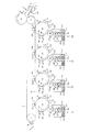
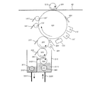
以下、本発明の実施の形態について図面を参照しながら説明する。図1は本発明の実施形態に係る画像形成装置の主要構成を示した図であり、図2は本発明の実施形態に係る画像形成装置において、イエロー(Y)色における画像形成部、現像装置(現像部)の主要構成を示した図である。 Hereinafter, embodiments of the present invention will be described with reference to the drawings. FIG. 1 is a diagram showing a main configuration of an image forming apparatus according to an embodiment of the present invention. FIG. 2 is a diagram illustrating an image forming unit and a developing device for yellow (Y) color in the image forming apparatus according to the embodiment of the present invention. FIG. 6 is a diagram illustrating a main configuration of (developing unit).
図1に示されるように、本実施形態の画像形成装置は、転写ベルト40と、感光体10Y、10M、10C、10Kを主要構成とする4つの画像形成部と、各感光体10Y、10M、10C、10K(本発明における「潜像担持体」)に対応して配設された4つの現像装置30Y、30M、30C、30Kと、図中、転写ベルト40の右側に配設されている2次転写部と、図中、転写ベルト40の左側に配設されているクリーニング部などによって構成されている。
As shown in FIG. 1, the image forming apparatus according to the present embodiment includes a
以下、画像形成部及び現像装置30Y、30M、30C、30Kについては、各色の画像形成部及び現像装置の構成は同様であるため、イエロー(Y)の画像形成部及び現像装置に基づいて説明する。
Hereinafter, the image forming unit and the developing
現像部30Yは、液体現像剤により感光体10Y上に形成された潜像を現像する装置であって、現像ローラー20Yと、中間ローラー32Yと、アニロクスローラー33Yと、液体現像剤を貯蔵する液体現像剤容器31Y、現像ローラー20Y上のトナーを帯電させ
るトナー帯電器22Yを主な構成要素としている。
The developing
現像ローラー20Yの外周には、クリーニングブレード21Y、中間ローラー32Y、トナー帯電器22Yが配されている。中間ローラー32Yは、その表面を現像ローラー20Yとアニロクスローラー33Yに当接させており、その外周には中間ローラークリーニングブレード34Yが配設されている。
A
アニロクスローラー33Yには、現像剤貯留部311Yから汲み上げた液体現像剤の量を調整する規制部材35Yが当接している。なお、本実施形態の現像装置のように中間ローラー32Yを用いた3ローラー方式では、中間ローラー32Yがアニロクスローラー33Yに当接することで液体現像剤の量を調整することが可能であるため、この規制部材35Yを配設しない構成とすることも可能である。
The
現像剤貯留部311Yには、搬送経路723Yを介して図示しない現像剤供給部から液体現像剤が供給される。なお、本実施形態では、仕切板313Yの両端部が中央部よりも一段低い形状を有しており、この一段低い部分にて液体現像剤を現像剤貯留部311Yから回収液貯留部312Y側に溢れさせることで、現像剤貯留部311Yの液位を一定に保っている。
A liquid developer is supplied to the
回収液貯留部312Yでは、その内部に配設された回収オーガ37Yにより、現像剤貯留部311Yから溢れた液体現像剤と各種ブレードにて回収された液体現像剤を含む回収液が回収オーガ37Yにて搬送され、移送経路721Yを介して現像剤供給部に回収される。回収された回収液は、現像剤補給部にて濃度調整された後、再度、移送経路723Yを介して供給されることで再利用を図ることが可能となっている。
In the recovery
現像剤容器31Yに収容されている液体現像剤は、従来一般的に使用されているIsopar(商標:エクソン)をキャリアとした低濃度(1〜2wt%程度)かつ低粘度の、常温で揮発性を有する揮発性液体現像剤ではなく、高濃度かつ高粘度の、常温で不揮発性を有する不揮発性液体現像剤である。すなわち、本発明における液体現像剤は、熱可塑性樹脂中へ顔料等の着色剤を分散させた平均粒径1μmの固形子を、有機溶媒、シリコーンオイル、鉱物油又は食用油等の液体溶媒中へ分散剤とともに添加し、トナー固形分濃度を約25%とした高粘度(HAAKE RheoStress RS600を用いて、25℃の時のせん断速度1000(1/s)のときの粘弾性が30〜300mPa・s程度)の液体現像剤である。
The liquid developer contained in the
アニロクスローラー33Yは、中間ローラー32Yに対して液体現像剤を供給して塗布する塗布ローラーとして機能する。このアニロクスローラー33Yは、円筒状の部材であり、表面に現像剤を担持し易いように表面に微細且つ一様に螺旋状に彫刻された溝による凹凸面が形成されたローラーである。このアニロクスローラー33Yにより、現像剤貯留部311Yから現像ローラー20Yへと液体現像剤が供給される。装置動作時においては、図に示すようにアニロクスローラー33Yは時計回りに回転して、中間ローラー32Yに液体現像剤を塗布する。
The
規制部材35Yは、厚さ200μm程度の金属ブレードであり、アニロクスローラー33Yの表面に当設し、アニロクスローラー33Yによって坦持搬送されてきた液体現像剤の膜厚、量を規制し、現像ローラー20Yに供給する液体現像剤の量を調整する。
The regulating
中間ローラー32Yは、円筒状の部材であり、回転軸を中心に図に示すように、現像ローラー20Yと同様、反時計回りに回転し、現像ローラー20Yに対しカウンター当接する。中間ローラー32Yは現像ローラー20Yと同様に、金属製の内心の外周部に弾性層
を設けて構成される。
The
中間ローラー32Yと現像ローラー20Yとの当接位置下流には、中間ローラークリーニングブレード34Yが当接して配設され、現像ローラー20Yに供給されなかった液体現像剤を掻き取って現像剤容器31Y内の回収液貯留部312Yに回収する。
An intermediate
現像ローラー20Yは、円筒状の部材であり、回転軸を中心に図に示すように反時計回りに回転する。現像ローラー20Yは、鉄等金属製の内芯の外周部に、ポリウレタンゴム、シリコンゴム、NBR、PFAチューブなどの弾性層を設けたものである。現像ローラー20Yには現像バイアスが印加されることとなるが、現像バイアスは、この金属製の内心に印加される。
The developing
現像ローラークリーニングブレード21Yは、現像ローラー20Yが感光体10Yと当接する現像ニップ部より現像ローラー20Yの回転方向の下流側に配設され、現像ローラー20Yに残存する液体現像剤を掻き落として除去する。現像残りの現像剤は、現像ローラークリーニングブレード21Yによって掻き落として除去され現像剤容器31Y内の回収液貯留部312Yに滴下して再利用される。
The developing
トナー帯電器22Y(本発明における「帯電器」)は、現像ローラー20Yの表面の帯電バイアスを増加させる電界印加手段であり、現像ローラー20Yによって搬送される液体現像剤は、このトナー帯電器22Yと近接する位置でコロナ放電による電界が印加され帯電される。
The
画像形成部は、感光体10Yの外周の回転方向に沿って順に配設された、2基のコロナ帯電器11Y、11Y’、露光ユニット12Y、感光体スクイーズ装置、1次転写部50Y、感光体クリーニングブレード18Yなどによって構成される。この画像形成部は感光体10Yの外周上、露光ユニット12Yと第1スクイーズローラー13Yとの間において現像部30Yの現像ローラー20Yと当接する。
The image forming unit is arranged in order along the rotation direction of the outer periphery of the
感光体10Yは、外周面にアモルファスシリコン感光体などの感光層が形成された円筒状の部材からなる感光体ドラムであり、時計回りの方向に回転する。
The
2基のコロナ帯電器11Y、11Y’は、感光体10Yと現像ローラー20Yとのニップ部より感光体10Yの回転方向の上流側に配置され、図示しない電源装置から電圧が印加され、感光体10Yをコロナ帯電させる。露光ユニット12Y(本発明における「露光部」)は、コロナ帯電器11Yより感光体10Yの回転方向の下流側において、コロナ帯電器11Y、11Y’によって帯電された感光体10Y上に光を照射し、感光体10Y上に潜像を形成する。
The two
1次転写部50Yの上流側に配置される感光体スクイーズ装置は、感光体10Yに対向して現像ローラー20Yの下流側に配置されている。この感光体スクイーズ装置は、感光体10Yに摺接して回転する弾性ローラー部材からなる第1スクイーズローラー13Y、第2スクイーズローラー13Y’、感光体スクイーズローラークリーニングブレード14Y、14Y’にて構成され、感光体10Y上に現像されたトナー像から余剰なキャリア液及び本来不要なカブリトナーを回収(スクイーズ)し、顕像(トナー像)内のトナー粒子比率を上げる機能を有する。なお、感光体スクイーズローラー13Y、13Y’には、カブリトナーを感光体スクイーズローラー13Y、13Y’側に誘引するためバイアス(電圧)が印加されている。
The photosensitive member squeeze device disposed on the upstream side of the
感光体スクイーズローラークリーニングブレード14Y、14Y’は、各感光体スクイ
ーズローラー13Y、13Y’に当接して設けられ、回収されたキャリア液やカブリトナーを含んだ液体現像剤を掻き落として、現像剤容器31Y内の回収液貯留部312Yに滴下する。
The photoconductor squeeze
上記の第1感光体スクイーズローラー13Y、第2感光体スクイーズローラー13Y’からなるスクイーズ装置を経た感光体10Y表面は、1次転写部50Yに進入する。この1次転写部50Yでは、感光体10Yに現像された現像剤像を1次転写バックアップローラー51Yにより転写ベルト40へ転写する。この1次転写部50Yにおいては、1次転写バックアップローラー51Yに印加される転写バイアスの作用によって、感光体10Y上のトナー像は転写ベルト40側に転写される。ここで、感光体10Yと転写ベルト40は等速度で移動する構成であり、回転及び移動の駆動負荷を軽減するとともに、感光体10Yの顕像トナー像への外乱作用を抑制している。
The surface of the
1次転写部50Yの下流側において、感光体10Yと当接している感光体クリーニングブレード18Yは、感光体10Y上のキャリア成分リッチな液体現像剤をクリーニングする。
On the downstream side of the
転写ベルト40(転写部材)は、ポリイミド基層上にポリウレタンの弾性中間層を設け、さらにその上にPFA表層が設けられている三層構造となっている。この転写ベルト40は、ベルト駆動ローラー41、テンションローラー42にて張架され、PFA表層側においてトナー像が転写されるようにして用いられる。本実施形態の画像形成装置では、転写させるための部材として、転写ベルト40を用いているが、ベルトに限らず、ローラー、ドラムなど各種の転写部材を採用することも可能である。
The transfer belt 40 (transfer member) has a three-layer structure in which an elastic intermediate layer of polyurethane is provided on a polyimide base layer and a PFA surface layer is provided thereon. The
感光体10Y、10M、10C、10Kと転写ベルト40を挟んで1次転写バックアップローラー51Y、51M、51C、51Kが対向配置することで形成される1次転写部50Y、50M、50C、50Kでは、感光体10Y、10M、10C、10Kとの当接位置を転写位置として、現像された感光体10Y、10M、10C、10K上の各色のトナー像を転写ベルト40上に順次重ねて転写し、転写ベルト40上にフルカラーのトナー像を形成する。
In the
2次転写ユニット60は、2次転写ローラー61が転写ベルト40を挟んでベルト駆動ローラー41と対向配置され、両者によって2次転写部(ニップ部)を形成する。この2次転写部では、転写ベルト40上に形成された単色あるいはフルカラーのトナー像が転写材搬送経路Lにて搬送される用紙、フィルム、布等の転写材に転写される。さらに、シート材搬送経路Lの下流には、図示しない定着ユニットが配設され、転写材上に転写された単色のトナー像やフルカラーのトナー像に熱や圧力を加えて定着させる。
In the
2次転写ユニットに対する転写材の供給は給紙装置(不図示)によって行われる。給紙装置にセットされた転写材は、所定のタイミングにて一枚ごとに転写材搬送経路Lに送り出されるようになっている。転写材搬送経路Lでは、ゲートローラー101、101’によって転写材を2次転写部まで搬送し、転写ベルト40上に形成された単色あるいはフルカラーのトナー像を転写材に転写する。
The transfer material is supplied to the secondary transfer unit by a paper feeding device (not shown). The transfer material set in the paper feeding device is sent to the transfer material conveyance path L one by one at a predetermined timing. In the transfer material conveyance path L, the transfer material is conveyed to the secondary transfer portion by the
テンションローラー42は、駆動ローラー41と共に中間転写体40を張架しており、中間転写体40のテンションローラー42に張架されている箇所にて、転写ベルト40をクリーニングするクリーニングブレード46が当接して配設される。
The
このように本実施形態の現像装置30Y、画像形成装置では、アニロクスローラー33Yで汲み上げた液体現像剤を、ウィズ回転の中間ローラー32Yに転移させ、さらにカウ
ンター回転の現像ローラー20Yで摺りきり界面をならすことで4〜10μmの均一な薄膜が形成される。さらに、現像ローラー20Yに対向して設けられたトナー帯電器22Yによって液体現像剤の帯電を補い、かつ、現像ローラー20Y側に圧縮することで、非画像部に余分なトナーが付着すること(カブリ)を抑制すると共に、画像部における均一性を向上させることが可能となる。
As described above, in the developing
本実施形態では、トナー帯電器22Yとして、コロトロン、スコロトロン等、コロナ放電を行うことで液体現像剤を帯電させる装置を用いているが、このような形態以外に、帯電ローラーを用いることとしてもよい。なお、トナー帯電器22Yによる帯電・圧縮をプリチャージと呼ぶこともある。
In this embodiment, as the
図2に示されるよう現像ローラー20Yの周囲には、トナー帯電器22Yと、現像ローラー20Yと感光体10Yのニップ位置の間に電位測定部23Yが配設されている。この電位測定部23Yにて液体現像剤がプリチャージされた後で、かつ現像直前の液体現像剤の表面電位(第2電位)、並びに、液体現像剤が塗布されていない状態の現像ローラー20Yの表面電位(第1電位)を計測することが可能となる。
As shown in FIG. 2, around the developing
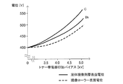
図3は、トナー帯電器22Yへの印加バイアスに対する各種電位の関係を示す図である。プリチャージ前の現像ローラー20Yの表面電位は、現像ローラー20Yに印加される現像バイアスVdと略等しい(約400[V])。トナー帯電器22Yに印加するバイアスを高くすることで、液体現像剤層の表面電位である第2電位(以下、V2と記載する)、現像ローラー20Y自体の表面電位である第1電位(以下、V1と記載する)は、共に現像バイアスよりも高くなっていく。ここでV2とV1の電位差(V2−V1)は、液体現像剤層に付与された電荷による電位上昇分と考えることができるので、V2−V1を測定することで、液体現像剤の帯電・圧縮状態を判断することが可能となる。さらに、V1を測定することで、現像時の電位コントラスト状態を判断することが可能となる。
FIG. 3 is a diagram showing the relationship of various potentials with respect to the bias applied to the
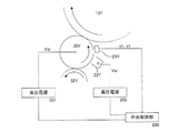
図4は、本発明の実施形態に係るトナー帯電器、現像ローラーのバイアス制御構成を示す図である。電位測定部23Yは、現像ローラー20Yの周囲であって、トナー帯電器22Yと、現像ローラー20Yと感光体10Yにて形成されるニップ部の間に配設されている。この電位測定部23Yは、現像ローラー20Yに塗布された液体現像剤の電位(V2)、液体現像剤が塗布されていない状態の現像ローラー20Yの電位(V1)を測定し、中央制御部200に出力する。電位測定部23Yには、2センサー方式、1センサー方式などを採用することができるが、センサー(電位検出部材)の配設位置などの具体的構成については後述する。
FIG. 4 is a diagram illustrating a bias control configuration of the toner charger and the developing roller according to the embodiment of the present invention. The
中央制御部200は、V1、V2に基づいて、高圧電源202、高圧電源201の制御を行う。ここで、高圧電源202は、トナー帯電器22Yに印加するバイアスを制御し、高圧電源201は、現像ローラー22Yに印加する現像バイアスを制御する。特に本実施形態では、V2とV1の差分に基づいて高圧電源202が制御され、現像ローラー20Y上の液体現像剤の帯電状態が調整される。
The
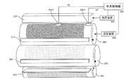
図5は、本発明の実施形態に係る電位測定部23Yの構成を説明するための図である。本実施形態の電位測定部23Yには、少なくとも2箇所において現像ローラー20Y上の電位を測定する電位検出部材231Y、232Yが配設された2センサー方式が採用されている。なお、第1電位検出部材231Y、第2電位検出部材232Yの少なくとも一方について複数配設する場合には、それぞれの計測電位の平均をV1、V2として採用することとしてもよい。
FIG. 5 is a diagram for explaining the configuration of the
第2電位検出部材232Yは、現像ローラー20Y上において液体現像剤が塗布される
領域、すなわち、アニロクスローラー33Yにおいて液体現像剤を汲み上げる凹凸面に対応する領域における電位(第2電位)を測定可能とする位置に配設されている。第1電位検出部材231Y、第2電位検出部材232Y共に、非接触で対向する位置の電位を検出するセンサーである。
The second
一方、第1電位検出部材231Yは、現像ローラー20Y上において液体現像剤が塗布されない領域の電位(V1)を検出する位置に配設される。図6には、第1電位検出部材231Yの配設位置の詳細が示されている。この図は、現像ローラー20Yの端部付近における側面図であって、第1電位検出部材231Yは、図に示される位置に配設される。第1電位検出部材231Yは、その現像ローラー20Yの軸方向における幅Lが、液体現像剤が塗布されない領域であって、トナー帯電器22Yによる帯電領域、及び、現像ローラークリーニングブレード21Yもしくは中間ローラー32Yによる除電領域に含まれる位置に配置される。このような位置で第1電位、すなわち、現像ローラー20Y自体の表面電位を測定することが可能となる。
On the other hand, the first
本実施形態では、現像ローラークリーニングブレード21Yもしくは中間ローラー32Yによる除電性能を向上させるため、現像ローラークリーニングブレード21Yもしくは中間ローラー32Yは、体積抵抗率が103〜107Ωcm、または、表面抵抗率が104
〜1011Ω/cm2の部材で構成され、さらに図示しない高圧電源から現像バイアスVd
と等バイアスが印加されている。現像ローラー20Y表面にはトナー帯電器22Yからの電荷が堆積するため、現像ローラーが1回転するごとに電荷を除去する必要がある。したがって現像ローラークリーニングブレード21Yまたは中間ローラー32Yを所定の範囲の抵抗部材で構成することで、現像ローラーとの当接部分から電荷を逃がすことができるため、現像ローラー20Y表面の除電が可能となり、プリチャージ直前の現像ローラー20Yの表面電位を現像バイアスVdと略等しくすることが可能となる。
In this embodiment, in order to improve the static elimination performance by the developing
10 11 Ω / cm 2 , and a developing bias Vd from a high voltage power source (not shown).
And an equal bias is applied. Since the charge from the
プリチャージによって現像ローラー20Y表面に堆積した電荷を除電するために所定範囲の抵抗に調整された現像ローラークリーニングブレード21Yの幅もしくは中間ローラー32Yの幅は、トナー帯電器22Yによる帯電領域(幅)よりも大きくなっている。現像ローラー20Y表面に堆積した電荷の除電効果を高めるために現像ローラークリーニングブレード21Yおよび中間ローラー32Yには現像バイアスVdよりも低いバイアスを印加することもできる。
The width of the developing
図7は、本発明の実施形態に係るバイアス制御処理を示すフロー図である。バイアス制御処理は、印刷動作開始時、印刷動作実行中など、適宜タイミングにて行うことができる。このバイアス制御処理が開始されると、まず、現像ローラー20Yに印加する現像バイアスVd、トナー帯電器22Yに印加するバイアスVwを初期値に設定するとともに、現像ローラー20Y、中間ローラー32Y等の駆動を開始させる(S102)。液体現像剤が現像ローラー20Y上に塗布され、ある程度安定した状態となったときに、電位測定部23Yにて、液体現像剤が塗布されない領域の第1電位V1、液体現像剤が塗布された領域の第2電位V2を測定し、それらの差分が求められる。
FIG. 7 is a flowchart showing a bias control process according to the embodiment of the present invention. The bias control process can be performed at an appropriate timing such as when the printing operation starts or during the printing operation. When this bias control process is started, first, the developing bias Vd applied to the developing
この差分が液体現像剤層に付与された電荷による電位上昇分となる。この電位上昇分が所定範囲内にある場合には、液体現像剤自体の帯電量は好適な範囲にある。一方、差分が所定範囲を外れている場合には、液体現像剤層のトナー帯電器22Yに印加するバイアスを調整することで液体現像剤の帯電量が好適な範囲となるように調整される。具体的には、差分が所定範囲の下限値よりも小さい場合には、トナー帯電器22Yに印加するバイアスVwを一定量上昇させる。また、差分が所定範囲の上限値よりも大きい場合には、トナー帯電器22Yに印加するバイアスVwを一定量下降させる。S103、S105の処理を繰り返すことで、差分(V2−V1)は好適な範囲に収められる。
This difference is the potential increase due to the charge applied to the liquid developer layer. When this potential increase is within a predetermined range, the charge amount of the liquid developer itself is in a suitable range. On the other hand, when the difference is out of the predetermined range, the charging amount of the liquid developer is adjusted to be within a suitable range by adjusting the bias applied to the
本実施形態では、さらに、現像ローラー20Y自体の表面電位についても適正値となるように制御し、現像コントラストおよび逆コントラストを好適な条件に保つこととしている。S104では、この現像ローラー20Yの表面電位を示す第1電位がV1*(V1の
適正値)に対し±5[V]の範囲内にあるか否かを判定することで適正値となっているか判断される。適正値にある場合にはバイアス制御処理を終了する(S101)。一方、適正値でない場合には、現像バイアスVdを調整することで適正化が図られる。具体的には、V1が適正値よりも大きい場合には現像バイアスVdを下げ、V1適正値よりも小さい場合には現像バイアスVdを上昇させる。
In the present embodiment, the surface potential of the developing
S106にて、現像バイアスVdを変更した場合には、現像ローラー20Yの表面電位である第1電位V1、液体現像剤の表面電位である第2電位V2もその影響を受けることとなる。そのため、本実施形態では、S103以降の処理を繰り返し実行することで、差分(V2−V1)、V1ともに適正値に保つこととしている。
When the developing bias Vd is changed in S106, the first potential V1 that is the surface potential of the developing
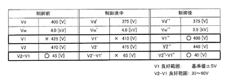
図8、図9は、本発明の実施形態に係るバイアス制御処理の具体例を示したものである。ここでは、液体現像剤にシアン色(C)のトナーを使用した場合を例に取り説明する。制御前(初期値)の現像バイアスVd=400[V]、トナー帯電器22への印加バイアスVw=4.0[kV]とした場合、電位測定部23Yにて測定される各電位は、V2=470[V]、V1=425[V]となり、差分V2−V1=45[V]となる。
8 and 9 show a specific example of the bias control process according to the embodiment of the present invention. Here, a case where cyan (C) toner is used as the liquid developer will be described as an example. When the development bias Vd before control (initial value) is 400 [V] and the bias applied to the toner charger 22 is Vw = 4.0 [kV], each potential measured by the
ここで液体現像剤中のトナーの帯電・圧縮状態が好適な条件となる差分(V2−V1)の範囲は30〜60[V]としている。差分の範囲は、液体現像剤に用いるキャリアオイルの導電率、トナーを形成する樹脂または分散剤または電荷制御剤または顔料の特性、現像ローラーの体積抵抗率および表面抵抗率など各種条件によって決定される。 Here, the range of the difference (V2−V1) where the charged / compressed state of the toner in the liquid developer is a suitable condition is 30 to 60 [V]. The range of the difference is determined by various conditions such as the conductivity of the carrier oil used for the liquid developer, the characteristics of the resin or dispersant forming the toner, the charge control agent or the pigment, the volume resistivity and the surface resistivity of the developing roller. .
制御前では差分(V2−V1)の値は45[V]であって、条件を満たしているものの、現像ローラー20Yの表面電位V1は、現像バイアスVdより大きくなっており、所望の現像ローラー20Yの表面電位V*より25[V]高くなっている。したがって、現像
ローラー20Yの表面電位V1を所望の値400[V]にするために現像バイアスをVd'=Vd−25[V]=375[V]に変更する。
Before the control, the value of the difference (V2−V1) is 45 [V], which satisfies the condition, but the surface potential V1 of the developing
現像バイアスVdを調整した結果、V1'=410[V]、V2'=475[V]となり、差分はV2'−V1'=65[V]に拡大され、好適な条件を外れることとなる。またV1'についても基準値を外れることとなる。そのため、トナー帯電器22への印加バイア
スVw'=3.9[V]とし、トナー帯電器22からの放電量を減少させることで、V1''=400V、V2''=440[V]に、差分V2''−V1''=40[V]にすることで
、現像ローラー20Yの表面電位V1''、及び、差分V2''−V1''は共に好適な範囲に調整される。この制御結果をまとめたものが図9に示されている。
As a result of adjusting the developing bias Vd, V1 ′ = 410 [V] and V2 ′ = 475 [V] are obtained, and the difference is expanded to V2′−V1 ′ = 65 [V], which is outside the preferable condition. Further, V1 ′ is also out of the reference value. Therefore, the bias applied to the toner charger 22 is set to Vw ′ = 3.9 [V], and the discharge amount from the toner charger 22 is reduced, so that V1 ″ = 400 V and V2 ″ = 440 [V]. By setting the difference V2 ″ −V1 ″ = 40 [V], the surface potential V1 ″ of the developing
図1に示されるような複数色を用いる画像形成装置では、各色液体現像剤の含有成分の違いにより、差分(V2−V1)が良好となる範囲が異なったものとなる。各色の固形分粒子の着色顔料として、イエロー(Y)ではアゾ系顔料および縮合多環系顔料、マゼンタ(M)ではアゾ系顔料、縮合アゾ顔料および縮合多環系顔料、シアン(C)ではフタロシアニン系顔料および縮合多環系顔料に代表される高分子有機化合物が用いられており、これらY、M、C各色の液体現像剤は、絶縁性が高いことが知られている。一方、ブラック(Bk)ではカーボンブラックに代表される導電性を持つ無機顔料が多く用いられている。したがってY、M、C、とBkでは液体現像剤としての導電性が異なり、Bkの液体現像剤の方が高い電気導電性を有する。 In the image forming apparatus using a plurality of colors as shown in FIG. 1, the range in which the difference (V2−V1) is good differs depending on the difference in the components contained in each color liquid developer. As color pigments for solid particles of each color, azo pigments and condensed polycyclic pigments for yellow (Y), azo pigments, condensed azo pigments and condensed polycyclic pigments for magenta (M), and phthalocyanines for cyan (C) High molecular organic compounds represented by pigments and condensed polycyclic pigments are used, and these Y, M, and C color liquid developers are known to have high insulation properties. On the other hand, in black (Bk), many inorganic pigments having conductivity represented by carbon black are used. Therefore, Y, M, C, and Bk have different conductivity as a liquid developer, and Bk liquid developer has higher electrical conductivity.
図10は、トナー色(シアン(C)、ブラック(Bk))の違いによる帯電量を示す図であり、図11は、トナー色の違いによるV2−V1の良好範囲を示す図である。図10に示されるようにCとBkを比べると、トナー帯電器22にて同じバイアスを印加した場合においてBkの方がV2は低くなる。これは同量のプリチャージ電荷を付与してもBkの方が液体現像剤表面に電荷が堆積しにくいことを起因とするものである。したがって、導電性の高いBkについて、その差分(V2−V1)が良好となる範囲は、他色(Y、M、C)よりも高いものとなる。バイアス制御処理では、このような液体現像剤の特性の違いを考慮して差分(V2−V1)が好適となる範囲が決定される。 FIG. 10 is a diagram showing the charge amount due to the difference in toner color (cyan (C), black (Bk)), and FIG. 11 is a diagram showing the good range of V2-V1 due to the difference in toner color. As shown in FIG. 10, when C and Bk are compared, V2 is lower for Bk when the same bias is applied by the toner charger 22. This is because even when the same amount of precharged charge is applied, Bk is less likely to accumulate charges on the surface of the liquid developer. Therefore, the range in which the difference (V2−V1) is favorable for Bk having high conductivity is higher than those of other colors (Y, M, C). In the bias control process, a range in which the difference (V2−V1) is suitable is determined in consideration of the difference in characteristics of the liquid developer.
図12は、本発明の他の実施形態に係る電位検出部材の配置を示す図である。図5では、2つの電位検出部材231Y、232Yを使用した2センサー方式の電位測定部23Yについて説明したが、電位測定部23Yは1つの電位検出部材230Yにて構成することも可能である。この場合、図に示されるように電位検出部材230Yは、図5の第2電位検出部材232Yと同様、現像ローラー20Yにおいて液体現像剤が塗布される位置の電位を検出できる位置に配設される。
FIG. 12 is a diagram showing the arrangement of potential detection members according to another embodiment of the present invention. In FIG. 5, the two-sensor type
このような位置では、液体現像剤を塗布しない部分の電位(第1電位)を測定する処理が必要とされる。したがって、印刷動作開始時、所定印刷時間経過後(例えば1時間)、所定枚数印刷後(例えば1000ページ)に印刷動作を停止して、現像ローラー20Yに液体現像剤を塗布しない期間において、液体現像剤が塗布されていない現像ローラー20Yの表面電位を検出し第1電位V1として出力する。
In such a position, a process for measuring the potential (first potential) of the portion where the liquid developer is not applied is required. Accordingly, at the start of the printing operation, after a predetermined printing time has elapsed (for example, 1 hour), after a predetermined number of sheets have been printed (for example, 1000 pages), the printing operation is stopped, and the liquid development is performed in a period in which the liquid developer is not applied to the developing
なお、印刷動作中、転写材(用紙)間に対応した位置は現像剤塗布が不要となるため、転写材の間に対応する位置において各種供給ローラー(アニロクスローラー33Y、またはアニロクスローラー33Yおよび中間ローラー32Y)を停止させ、液体現像剤が塗布されていない現像ローラー20Yの表面電位(第1電位)を測定することもできる。
In addition, during the printing operation, the developer coating is unnecessary at the positions corresponding to the transfer material (paper), and therefore various supply rollers (
なお、本明細書においては、種々の実施の形態について説明したが、それぞれの実施の形態の構成を適宜組み合わせて構成された実施形態も本発明の範疇となるものである。 Note that although various embodiments have been described in this specification, embodiments configured by appropriately combining the configurations of the respective embodiments are also included in the scope of the present invention.
10Y(以下、符号にYの付されているものは、M、C、K各色についても同様)…感光体(潜像担持体)、11Y…第1コロナ帯電器、11Y’…第2コロナ帯電器、12Y…露光ユニット(露光部)、13Y…第1スクイーズローラー、13Y’…第2スクイーズローラー、14Y…第1スクイーズローラークリーニングブレード、14Y’…第2スクイーズローラークリーニングブレード、18Y…感光体クリーニングブレード、20Y…現像ローラー(現像剤担持体)、21Y…現像ローラークリーニングブレード、22Y…トナー帯電器(帯電器)、23Y…電位測定部、230Y〜232Y…電位検出部材、30Y…現像部(現像装置)、31Y…現像剤容器、311Y…現像剤貯留部、312Y…回収液貯留部、313Y…仕切板、32Y…中間ローラー、33Y…アニロクスローラー、34Y…中間ローラークリーニングブレード、35Y…規制部材、36Y…攪拌オーガ、37Y…回収オーガ、40…転写ベルト、41…駆動ローラー、42…テンションローラー、50Y…1次転写部、51Y…1次転写バックアップローラー、60…2次転写ユニット、61…2次転写ローラー、62…2次転写ローラークリーニングブレード、63…2次転写ユニット回収貯留部、101、101’…ゲートローラー、102…転写材ガイド、200…中央制御部、201、202…高圧電源 10Y (Hereinafter, Y is the same for the colors M, C, and K.) Photoconductor (latent image carrier), 11Y ... first corona charger, 11Y '... second corona charge , 12Y ... exposure unit (exposure unit), 13Y ... first squeeze roller, 13Y '... second squeeze roller, 14Y ... first squeeze roller cleaning blade, 14Y' ... second squeeze roller cleaning blade, 18Y ... photoconductor cleaning Blade, 20Y ... developing roller (developer carrier), 21Y ... developing roller cleaning blade, 22Y ... toner charger (charger), 23Y ... potential measuring unit, 230Y to 232Y ... potential detection member, 30Y ... developing unit (development) Device), 31Y ... developer container, 311Y ... developer reservoir, 312Y ... recovered liquid reservoir, 313Y ... finishing Plate, 32Y ... Intermediate roller, 33Y ... Anilox roller, 34Y ... Intermediate roller cleaning blade, 35Y ... Restriction member, 36Y ... Agitation auger, 37Y ... Collection auger, 40 ... Transfer belt, 41 ... Drive roller, 42 ... Tension roller, 50Y ... primary transfer unit, 51Y ... primary transfer backup roller, 60 ... secondary transfer unit, 61 ... secondary transfer roller, 62 ... secondary transfer roller cleaning blade, 63 ... secondary transfer unit collection / storage unit, 101, 101 '... Gate roller, 102 ... Transfer material guide, 200 ... Central control unit, 201, 202 ... High voltage power supply
Claims (8)
前記現像剤担持体に担持された液体現像剤を帯電させる帯電部と、
液体現像剤が担持されていない位置での前記現像剤担持体の電位である第1の電位と、液体現像剤が担持されて前記帯電部で帯電される位置での前記現像剤担持体の電位である第2の電位とを測定する電位測定部と、
前記電位測定部で測定された前記第1の電位と前記第2の電位の差分を算出し、算出された前記差分に基づいて液体現像剤への帯電を調整する制御部と、を有することを特徴とする現像装置。 A developer carrier that carries a liquid developer containing toner and carrier liquid and to which a development bias is applied;
A charging unit for charging the liquid developer carried on the developer carrying member;
A first potential which is a potential of the developer carrying member at a position where the liquid developer is not carried, and a potential of the developer carrying member at a position where the liquid developer is carried and charged by the charging unit. A potential measuring unit that measures the second potential,
A controller that calculates a difference between the first potential and the second potential measured by the potential measuring unit, and adjusts charging of the liquid developer based on the calculated difference. A developing device.
前記現像剤担持体が液体現像剤を担持していない時に前記電位検出部材に前記第1の電位を測定させると共に、前記現像剤担持体が液体現像剤を担持している時に前記電位検出部材に前記第2の電位を測定させる電位測定制御部と、を有する請求項1または請求項2に記載の現像装置。 The potential measurement unit includes a potential detection member that detects a potential of the developer carrier at a position where the liquid developer of the developer carrier is carried;
When the developer carrying member is not carrying a liquid developer, the potential detecting member measures the first potential, and when the developer carrying member is carrying a liquid developer, the potential detecting member is The developing device according to claim 1, further comprising: a potential measurement control unit that measures the second potential.
前記現像剤担持体の液体現像剤を担持しない位置で、かつ前記帯電部で帯電される位置の前記現像剤担持体の電位を測定する第1電位検出部材と、
前記現像剤担持体の液体現像剤を担持する位置で、前記現像剤担持体の電位を測定する第2電位検出部材と、を有し、
前記第1電位検出部材で前記第1の電位を検出するとともに、前記第2電位検出部材で前記第2の電位を検出する請求項1または請求項2に記載の現像装置。 The potential measuring unit includes:
A first potential detecting member that measures the potential of the developer carrying member at a position where the developer carrying member does not carry the liquid developer and is charged by the charging unit;
A second potential detecting member that measures the potential of the developer carrying member at a position of the developer carrying member carrying the liquid developer;
The developing device according to claim 1, wherein the first potential is detected by the first potential detection member, and the second potential is detected by the second potential detection member.
前記クリーニング部材は、前記現像剤担持体に印加されるバイアスと等しいか、略等しいバイアスが印加される請求項1から請求項4の何れか1項に記載の現像装置。 A cleaning member having a volume resistivity of 10 3 to 10 7 Ωcm for cleaning in contact with the developer carrying member;
The developing device according to claim 1, wherein the cleaning member is applied with a bias that is equal to or substantially equal to a bias that is applied to the developer carrying member.
前記潜像担持体に前記潜像を形成する露光部と、
トナー及びキャリア液を含む液体現像剤を担持するとともに現像バイアスが印加される現像剤担持体、及び前記現像剤担持体に担持された液体現像剤を帯電させる帯電部を有し、前記潜像担持体に形成された前記潜像を液体現像剤で現像する現像部と、
液体現像剤が担持されていない位置での前記現像剤担持体の電位である第1の電位と、液体現像剤が担持されて前記帯電部で帯電される位置での前記現像剤担持体第2の電位とを測定する電位測定部と、
前記電位測定部で測定された前記第1の電位と前記第2の電位の差分を算出し、算出された前記差分に基づいて液体現像剤への帯電を調整する制御部、を有することを特徴とする
画像形成装置。 A latent image carrier on which a latent image is formed;
An exposure unit that forms the latent image on the latent image carrier;
A latent image carrier having a developer carrier that carries a liquid developer containing toner and a carrier liquid and to which a developing bias is applied; and a charging unit that charges the liquid developer carried on the developer carrier. A developing unit for developing the latent image formed on the body with a liquid developer;
A first potential which is a potential of the developer carrying member at a position where the liquid developer is not carried, and a second developer carrying member at a position where the liquid developer is carried and charged by the charging unit. A potential measuring unit for measuring the potential of
A controller that calculates a difference between the first potential and the second potential measured by the potential measuring unit and adjusts charging of the liquid developer based on the calculated difference; An image forming apparatus.
液体現像剤が担持されていない位置での前記液体現像剤担持体の電位である第1の電位と、液体現像剤が担持されて前記帯電部で帯電される位置での前記現像剤担持体の電位である第2の電位とを測定し、
前記第1の電位と前記第2の電位の差分に基づいて液体現像剤への帯電を調整し、
前記現像剤担持体に担持された液体現像剤で、潜像担持体に形成された潜像を現像することを特徴とする画像形成方法。 Charging a liquid developer containing toner and carrier liquid carried on the developer carrying member;
A first potential which is a potential of the liquid developer carrying member at a position where the liquid developer is not carried; and a position of the developer carrying member at a position where the liquid developer is carried and charged by the charging unit. A second potential which is a potential,
Adjusting the charging of the liquid developer based on the difference between the first potential and the second potential;
An image forming method comprising developing a latent image formed on a latent image carrier with a liquid developer carried on the developer carrier.
Priority Applications (1)
| Application Number | Priority Date | Filing Date | Title |
|---|---|---|---|
| JP2010252854A JP2012103545A (en) | 2010-11-11 | 2010-11-11 | Developing device, image forming apparatus and method for forming image |
Applications Claiming Priority (1)
| Application Number | Priority Date | Filing Date | Title |
|---|---|---|---|
| JP2010252854A JP2012103545A (en) | 2010-11-11 | 2010-11-11 | Developing device, image forming apparatus and method for forming image |
Publications (1)
| Publication Number | Publication Date |
|---|---|
| JP2012103545A true JP2012103545A (en) | 2012-05-31 |
Family
ID=46393986
Family Applications (1)
| Application Number | Title | Priority Date | Filing Date |
|---|---|---|---|
| JP2010252854A Pending JP2012103545A (en) | 2010-11-11 | 2010-11-11 | Developing device, image forming apparatus and method for forming image |
Country Status (1)
| Country | Link |
|---|---|
| JP (1) | JP2012103545A (en) |
Cited By (1)
| Publication number | Priority date | Publication date | Assignee | Title |
|---|---|---|---|---|
| WO2019198836A1 (en) * | 2018-04-13 | 2019-10-17 | キヤノン株式会社 | Image formation device |
-
2010
- 2010-11-11 JP JP2010252854A patent/JP2012103545A/en active Pending
Cited By (3)
| Publication number | Priority date | Publication date | Assignee | Title |
|---|---|---|---|---|
| WO2019198836A1 (en) * | 2018-04-13 | 2019-10-17 | キヤノン株式会社 | Image formation device |
| JP2019184919A (en) * | 2018-04-13 | 2019-10-24 | キヤノン株式会社 | Image forming device |
| JP7023777B2 (en) | 2018-04-13 | 2022-02-22 | キヤノン株式会社 | Image forming device |
Similar Documents
| Publication | Publication Date | Title |
|---|---|---|
| US7590368B2 (en) | Image forming apparatus and method of cleaning intermediate transfer belt | |
| JP2010204469A (en) | Image forming method and image forming apparatus | |
| JP2012163583A (en) | Image forming apparatus and image forming method | |
| CN101533250B (en) | Image forming apparatus and image forming method | |
| JP5311015B2 (en) | Transfer device and image forming apparatus | |
| JP2012042582A (en) | Image forming apparatus and image forming method | |
| US10915038B2 (en) | Image forming apparatus | |
| WO2018101486A1 (en) | Image-forming device | |
| JP3650431B2 (en) | Liquid developing method and liquid developing apparatus for electrostatic latent image | |
| JP2010243553A (en) | Transfer device and image forming apparatus | |
| JP2011186016A (en) | Image forming apparatus and image forming method | |
| JP2012103639A (en) | Developing device, image forming apparatus and method for forming image | |
| JP5177381B2 (en) | Image forming apparatus and image forming method | |
| JP7483546B2 (en) | Image forming device | |
| JP2008170603A (en) | Image forming method and image forming apparatus using liquid developer | |
| JP4636293B2 (en) | Developing device and image forming apparatus | |
| JP3806135B2 (en) | Liquid developing electrophotographic apparatus | |
| JP3993935B2 (en) | Image forming apparatus | |
| JP2018138981A (en) | Developing device | |
| JP2021063872A (en) | Developing device and image forming apparatus | |
| JP2010128234A (en) | Transfer device and image forming apparatus | |
| JP2012173611A (en) | Transfer device and image forming apparatus | |
| JP2012103640A (en) | Image forming apparatus and method for forming image | |
| JP2022063650A (en) | Image forming apparatus | |
| JP2011069970A (en) | Image forming apparatus and image forming method |