JP2012105455A - Motor control device - Google Patents
Motor control device Download PDFInfo
- Publication number
- JP2012105455A JP2012105455A JP2010251915A JP2010251915A JP2012105455A JP 2012105455 A JP2012105455 A JP 2012105455A JP 2010251915 A JP2010251915 A JP 2010251915A JP 2010251915 A JP2010251915 A JP 2010251915A JP 2012105455 A JP2012105455 A JP 2012105455A
- Authority
- JP
- Japan
- Prior art keywords
- control device
- motor control
- clock
- noise
- level
- Prior art date
- Legal status (The legal status is an assumption and is not a legal conclusion. Google has not performed a legal analysis and makes no representation as to the accuracy of the status listed.)
- Granted
Links
Images








Landscapes
- Control Of Ac Motors In General (AREA)
Abstract
Description
本発明は、ノイズレベルを検出可能な電流検出回路を備えたモータ制御装置に関する。 The present invention relates to a motor control device including a current detection circuit capable of detecting a noise level.
本技術分野の背景技術として特許文献1がある。この特許文献1には、「アナログ・デジタル信号変換回路の出力を監視して耐ノイズ性を高める情報処理・制御装置およびそのノイズ耐量検知手段」が記載されている。
There is
上述のように特許文献1にはノイズ耐量検知手段が記載されている。しかし、特許文献1の情報処理・制御装置はノイズの大きさを時間幅として検出し、監視することしかできない。このような情報処理・制御装置では、例えば、非常に短い時間幅のノイズを検知することができない。また、例えば、ノイズ以外の原因で信号に乱れが生じた場合に検知することができない。
As described above,
そこで、本発明は、通常のノイズだけでなく非常に短い時間幅のノイズも検知することができる制御装置を提供する、例えば、ノイズを時間幅ではなく一定時間中のパルスの数として検出することができる制御装置を提供することを目的とする。 Therefore, the present invention provides a control device that can detect not only normal noise but also noise with a very short time width, for example, detecting noise as the number of pulses in a certain time instead of time width. It is an object of the present invention to provide a control device capable of performing the above.
また、本発明は、ノイズ以外の原因で信号に乱れが生じた場合にも検知することができる制御装置を提供することを目的とする。 It is another object of the present invention to provide a control device that can detect when a signal is disturbed due to a cause other than noise.
例えば、信号のパルス幅や信号同士の位相差を測定し、測定結果にばらつきが生じた際にはワーニング・アラームを出力し、一定時間以上HレベルあるいはLレベルとなった場合には故障と判断しワーニング・アラームを出力する制御装置を提供することを目的とする。 For example, it measures the pulse width of signals and the phase difference between signals, outputs a warning alarm when measurement results vary, and determines that a failure has occurred if the signal level is H level or L level for a certain period of time. It is an object of the present invention to provide a control device that outputs a warning alarm.
上記手段を解決するために、本発明は特許請求の範囲に記載した構成を採用する。
本発明は、上記課題を解決する手段を複数含んでいるが、その一例を挙げるならば、クロックに対するノイズを除去するためのデジタルフィルタの前後で一定時間中のクロック数の測定を行うことでノイズレベルを検出可能な電流検出回路を備えることを特徴とする。
In order to solve the above-described means, the present invention adopts the configurations described in the claims.
The present invention includes a plurality of means for solving the above-mentioned problems. For example, the noise is measured by measuring the number of clocks in a predetermined time before and after the digital filter for removing noise with respect to the clock. A current detection circuit capable of detecting the level is provided.
本発明のモータ制御装置は、制御回路からベースドライブ回路を介して供給されるゲート駆動信号によりスイッチング動作を行い直流電圧を変換して3相交流電力を出力するインバータ回路と、前記インバータ回路からサーボモータに供給される3相交流出力の電流を検出し、AD変換器によりアナログ信号からデジタル信号に変換されたデジタルデータを検出する電流検出装置と、を備えたモータ制御装置において、前記電流検出装置に前記デジタルデータ信号と前記AD変換器のクロック信号とが入力され、前記クロック信号に基づいてノイズレベルを検出することを特徴とする。 The motor control device of the present invention includes an inverter circuit that performs a switching operation by a gate drive signal supplied from a control circuit via a base drive circuit, converts a DC voltage, and outputs three-phase AC power, and a servo from the inverter circuit. A current detection device that detects a current of a three-phase AC output supplied to a motor and detects digital data converted from an analog signal into a digital signal by an AD converter. The digital data signal and the clock signal of the AD converter are input to and a noise level is detected based on the clock signal.
また、本発明のモータ制御装置は、前記クロック信号の一定時間中のクロック数の測定を行うことでノイズレベルを検出することを特徴とする。 The motor control device according to the present invention is characterized in that the noise level is detected by measuring the number of clocks of the clock signal during a predetermined time.
また、本発明のモータ制御装置は、前記AD変換器から出力された前記クロック信号及び前記デジタルデータ信号がHレベルである時間、Lレベルである時間をそれぞれ測定することにより前記クロック信号及び前記デジタルデータ信号のパルス幅を計測することを特徴とする。 Further, the motor control device of the present invention measures the clock signal and the digital signal by measuring the time when the clock signal and the digital data signal output from the AD converter are at the H level and the time when the digital data signal is at the L level, respectively. The pulse width of the data signal is measured.
また、本発明のモータ制御装置は、前記AD変換器から出力された前記クロック信号と前記デジタルデータ信号の位相差を測定することを特徴とする。 The motor control device according to the present invention is characterized in that a phase difference between the clock signal output from the AD converter and the digital data signal is measured.
また、本発明のモータ制御装置は、クロック数測定時間を変更することにより、ノイズ発生頻度を検知することを特徴とする。 In addition, the motor control device of the present invention is characterized by detecting the noise occurrence frequency by changing the clock number measurement time.
また、本発明のモータ制御装置は、クロック数測定異常、パルス幅測定異常、位相差測定異常が発生する頻度を計測し、ノイズ発生の頻度や大きさを検知することで、ノイズ源を特定することを特徴とする。 In addition, the motor control device of the present invention measures the frequency of occurrence of clock number measurement abnormality, pulse width measurement abnormality, and phase difference measurement abnormality, and identifies the noise source by detecting the frequency and magnitude of noise generation. It is characterized by that.
また、本発明のモータ制御装置では、前記電流検出回路が前記クロック信号のノイズを除去するデジタルフィルタを備えており、前記デジタルフィルタの前後において一定時間中のクロック数を測定し、前記デジタルフィルタの前後の一定時間中のクロック数を比較することを特徴とする。 In the motor control device of the present invention, the current detection circuit includes a digital filter that removes noise of the clock signal, measures the number of clocks during a predetermined time before and after the digital filter, It is characterized by comparing the number of clocks in a certain period before and after.
また、本発明のモータ制御装置は、前記デジタルフィルタの前後において、一定時間中のクロック数を測定し比較することで、前記デジタルフィルタの効果を知ることができることを特徴とする。 Further, the motor control device of the present invention is characterized in that the effect of the digital filter can be known by measuring and comparing the number of clocks in a predetermined time before and after the digital filter.
また、本発明のモータ制御装置は、検出したノイズレベルに応じて、前記電流検出回路内のデジタルフィルタの段数やフィルタ周波数の変更を行うことを特徴とする。 In addition, the motor control device of the present invention is characterized in that the number of digital filters in the current detection circuit and the filter frequency are changed according to the detected noise level.
また、本発明のモータ制御装置は、検出したノイズのレベルに応じてデジタルフィルタの段数やフィルタ周波数の変更を行い、それに応じて制御ゲインを最適値に自動調整することを特徴とする。 The motor control device of the present invention is characterized in that the number of stages of the digital filter and the filter frequency are changed according to the detected noise level, and the control gain is automatically adjusted to the optimum value accordingly.
本発明によれば、通常のノイズだけでなく非常に短い時間幅のノイズも検知することができる制御装置、またノイズ以外の原因で信号に乱れが生じた場合にも検知することができる制御装置を提供することができる。 According to the present invention, a control device capable of detecting not only normal noise but also noise having a very short time width, and a control device capable of detecting when a signal is disturbed due to a cause other than noise. Can be provided.
上記した以外の課題、構成及び効果は、以下の実施形態の説明により明らかにされる。 Problems, configurations, and effects other than those described above will be clarified by the following description of embodiments.
以下、本発明の実施の形態について図面を用いて説明する。 Hereinafter, embodiments of the present invention will be described with reference to the drawings.
本実施例では、電流検出回路の保護方式を有するモータ制御装置の例を説明する。
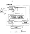
図1は、本実施例の電流検出回路の保護方式を有するモータ制御装置の構成図の例である。この図において1はインバータ回路で6個のスイッチング素子Q1〜Q6と、同じく6個のフライホイールダイオードD1〜D6からなる3相交流インバータ回路で構成されている。
In this embodiment, an example of a motor control device having a current detection circuit protection method will be described.
FIG. 1 is an example of a configuration diagram of a motor control device having a current detection circuit protection system according to the present embodiment. In this figure,
そして、このインバータ回路1は制御回路3からベースドライブ回路2を介して供給されるゲート駆動信号によりスイッチング動作し、PL線とNL線の間の直流電圧を3相交流電力に変換し、UL線とVL線、WL線の間に3相交流電圧を出力する働きをする。このため、ベースドライブ回路2と制御回路3は線路CS1を介して相互に所定の信号の授受が得られるように構成されている。
The
7はサーボモータで、図示していないトルク伝達系を介して、同じく図示していない被駆動部に連結され、インバータ回路1から供給される3相交流電力に応じて所定の方向に、所定のトルクで、所定の回転速度で回転し、加工製造ラインなどの駆動機構を所定の速度と所定の力で動かし、位置決めする働きをする。
A servo motor 7 is connected to a driven portion (not shown) via a torque transmission system (not shown), and is set in a predetermined direction in accordance with the three-phase AC power supplied from the
このとき、サーボモータ7の回転速度と回転位置はサーボモータ内蔵のエンコーダ8により検出され、線路CS3を介して制御回路3にフィードバッグされる。また、このとき、サーボモータ7のU相に流れる電流ULはAD変換器5により、W相に流れるWLはAD変換器6により、アナログ信号からデジタル信号に変換され、電流検出回路4によって検出される。この電流検出値が線路CS2を介して制御回路3にフィードバッグされ、インバータ回路1の制御に反映される。
At this time, the rotational speed and rotational position of the servo motor 7 are detected by the encoder 8 built in the servo motor and fed back to the control circuit 3 via the line CS3. At this time, the current UL flowing in the U phase of the servo motor 7 is converted from an analog signal to a digital signal by the
次に、電流検出について説明する。AD変換器5はサーボモータ7のU相に流れる電流ULをアナログ電圧として入力されると、自身が出力するクロックに同期したデジタルデータに変換して出力する。同様にAD変換器6はサーボモータ7のW相に流れる電流WLを、自身が出力するクロックに同期したデジタルデータに変換して出力する。AD変換器5及び6によって出力されたクロック及びデータは電流検出回路4の内部でシリアル−パラレル変換され、電流演算処理が行われる。
Next, current detection will be described. When the
このとき、AD変換器5及び6から出力されるクロック及びデータがノイズにより波形割れを起こした場合、電流検出回路4の内部では正常な電流演算処理ができず、正常なモータ制御を行うことができない。また、AD変換器自身の異常や故障により、クロック及びデータの周期が乱れたり、データがクロックに同期して出力されなくなったりした場合、つまりクロックとデータの位相差が変化してしまった場合も、正常な電流演算処理ができず、正常なモータ制御を行うことができない。
At this time, when the clock and data output from the
そこで、この実施形態では、以下のようにしてノイズの影響を防いだり、ノイズの影響を受けていることを上位装置に対して知らせたり、AD変換器自身の不良・故障を上位装置に知らせる。図2は本実施形態の電流検出回路である。AD変換器9によってモータ電流はクロックに同期しシリアルデータに変換され、電流検出回路10に入力される。 Therefore, in this embodiment, the influence of noise is prevented as described below, the host apparatus is notified that it is affected by the noise, and the host apparatus is notified of a failure / failure of the AD converter itself. FIG. 2 shows a current detection circuit according to this embodiment. The motor current is converted into serial data in synchronization with the clock by the AD converter 9 and input to the current detection circuit 10.
入力されたクロックはデジタルフィルタ11によりノイズが除去され、データはデジタルフィルタ12によりノイズが除去される。ノイズが除去されたクロック及びデータはシリアル−パラレル変換回路16によりシリアル−パラレル変換が行われ、制御回路18によって電流演算が行われる。
Noise is removed from the input clock by the digital filter 11, and noise is removed from the data by the
本電流検出回路には、ノイズによる誤動作を防ぐため、また、AD変換器自身やその周辺回路の故障・不良による誤動作を防ぐための保護回路を有している。クロック数測定回路13は、デジタルフィルタの前段と後段のクロックを監視し、規定した時間中のクロックの数を測定することができる。クロック、データのパルス幅測定回路14は、デジタルフィルタ通過後のクロック及びデータのパルス幅を測定することができる。
This current detection circuit has a protection circuit for preventing malfunction due to noise and preventing malfunction due to failure or failure of the AD converter itself or its peripheral circuits. The clock
クロックとデータの位相差測定回路15は、デジタルフィルタ通過後のクロック及びデータの位相差を測定することができる。この3つの測定回路はそれぞれ測定した値をワーニングレベルかアラームレベルか判定する機能を有しており、判定レベルを超えた場合には判定回路17へアラームあるいはワーニングを出力する。判定回路17はどの回路でアラームあるいはワーニングが発生したかを判定し、制御回路18へと通知する。
The clock and data phase
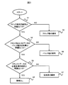
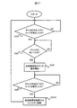
図2の判定回路17の動作を、図3のフロー図を用いて説明する。まず、処理ステップS1でクロック数測定結果が問題ないかチェックを行う。NO、つまりクロック数測定結果に問題がある場合にはクロック数の異常と判定し、図2の制御回路18へ通知する。YES、つまりクロック数測定結果に問題がないと判定し場合は、処理ステップS2へ進む。
The operation of the
処理ステップS2では、クロックあるいはデータのパルス幅測定結果に問題ないかチェックを行う。NO、つまりパルス幅測定結果に問題がある場合には、パルス幅の異常と判定し、図2の制御回路18へ通知する。YES、つまりパルス幅測定結果に問題がないと判定した場合は、処理ステップS3へ進む。
In processing step S2, it is checked whether there is a problem with the measurement result of the pulse width of the clock or data. If NO, that is, if there is a problem with the pulse width measurement result, it is determined that the pulse width is abnormal, and the
処理ステップS3では、クロックとデータの位相差測定結果に問題ないかチェックを行う。NO、つまり、位相差測定結果に問題がある場合には、位相差の異常と判定し、図2の制御回路18へ通知する。YES、つまり位相差測定結果に問題がないと判定した場合は、全ての測定結果に異常がないと判定する。
In processing step S3, it is checked whether there is a problem with the measurement result of the phase difference between the clock and data. If NO, that is, if there is a problem in the phase difference measurement result, it is determined that the phase difference is abnormal, and the
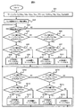
図2のクロック数測定回路13の動作を、図4のフロー図を用いて説明する。まず、処理ステップS11では、クロック数の測定結果が小さかったときに正常か異常かを判定するためのワーニングレベルNlwとアラームレベルNlaの設定及び、クロック数の測定結果が大きかったときに正常か異常かを判定するためのワーニングレベルNhwとアラームレベルNhaの設定を行う。
The operation of the clock
次に、処理ステップS12でクロック数測定カウンタの動作を開始し、クロック数の測定を行うクロック数の測定が終了したら処理ステップS13にて処理ステップS12で測定したクロック数NがワーニングレベルNhwよりも大きいか判定を行う。判定がYES、つまりクロック数NがワーニングレベルNhwよりも大きかった場合、処理ステップS14に進み、クロック数NがアラームレベルNhaよりも大きいか判定を行う。 Next, the operation of the clock number measurement counter is started in processing step S12, and when the measurement of the clock number for measuring the clock number is completed, the clock number N measured in processing step S12 in processing step S13 is higher than the warning level Nhw. Judge whether it is larger. If the determination is YES, that is, if the clock number N is larger than the warning level Nhw, the process proceeds to processing step S14 to determine whether the clock number N is larger than the alarm level Nha.
判定がYES、つまりクロック数NがアラームレベルNhaよりも大きかった場合、処理ステップS17に進み、上位装置に対しアラーム出力を行い、システムを停止させる。判定がNO、つまりクロック数NがアラームレベルNhaよりも小さかった場合、処理ステップS18に進み、上位装置に対しワーニング出力を行い、処理ステップS13に戻る。 If the determination is YES, that is, if the number of clocks N is larger than the alarm level Nha, the process proceeds to processing step S17, where an alarm is output to the host device, and the system is stopped. If the determination is NO, that is, if the number of clocks N is smaller than the alarm level Nha, the process proceeds to process step S18, a warning is output to the host device, and the process returns to process step S13.
処理ステップS13において、判定がNO、つまりクロック数NがワーニングレベルNhwよりも小さかった場合、処理ステップS15に進み、クロック数NがアラームレベルNlwよりも小さいか判定を行う。判定がYES、つまりクロック数NがワーニングレベルNlwよりも小さかった場合、処理ステップS16に進み、クロック数NがアラームレベルNlaよりも小さいか判定を行う。 If NO in process step S13, that is, if the clock number N is smaller than the warning level Nhw, the process proceeds to process step S15, where it is determined whether the clock number N is smaller than the alarm level Nlw. If the determination is YES, that is, if the clock number N is smaller than the warning level Nlw, the process proceeds to processing step S16 to determine whether the clock number N is smaller than the alarm level Nla.
判定がYES、つまりクロック数NがアラームレベルNlaよりも小さかった場合、処理ステップS19に進み、上位装置に対しアラーム出力を行い、システムを停止させる。判定がNO、つまりクロック数NがアラームレベルNlaよりも大きかった場合、処理ステップS110に進み、上位装置に対しワーニング出力を行い、処理ステップS13に戻る。 If the determination is YES, that is, if the number of clocks N is smaller than the alarm level Nla, the process proceeds to processing step S19, an alarm is output to the host device, and the system is stopped. If the determination is NO, that is, if the number of clocks N is larger than the alarm level Nla, the process proceeds to process step S110, a warning output is made to the host device, and the process returns to process step S13.
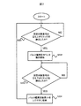
図4の処理ステップS12のクロック数測定カウンタの動作について、図5のフロー図を用いて説明する。まず処理ステップS121でクロック数を測定する時間を計測するための定周期カウンタを動作させる。次に、処理ステップS122にてクロック数を測定するためのカウンタを動作させる。処理ステップS123で定周期カウンタの値が規定の値になるまで待ち、処理ステップS124に進む。 The operation of the clock number measurement counter in process step S12 of FIG. 4 will be described with reference to the flowchart of FIG. First, in step S121, a fixed period counter for measuring the time for measuring the number of clocks is operated. Next, a counter for measuring the number of clocks is operated in processing step S122. In process step S123, the process waits until the value of the fixed period counter reaches a specified value, and the process proceeds to process step S124.
処理ステップS124で定周期カウンタの値をクリアし、処理ステップS125でクロック数測定結果Nをレジスタに保存し、処理ステップS126でクロック数測定カウンタの値をクリアし、処理ステップS121へ戻り、上記の動作を繰り返す。 In processing step S124, the value of the fixed cycle counter is cleared. In processing step S125, the clock number measurement result N is stored in the register. In processing step S126, the value of the clock number measurement counter is cleared, and the process returns to processing step S121. Repeat the operation.
図2のクロック、データのパルス幅測定回路14の動作を図6のフロー図を用いて説明する。まず、処理ステップS21では、Hレベル時のパルス幅の測定結果が小さかったときに正常か異常かを判定するためのワーニングレベルTHlwとアラームレベルTHlaの設定及び、Hレベル時のパルス幅の測定結果が大きかったときに正常か異常かを判定するためのワーニングレベルTHhwとアラームレベルTHhaの設定を行う。
The operation of the clock and data pulse
さらにLレベル時のパルス幅の測定結果が小さかったときに正常か異常かを判定するためのワーニングレベルTLlwとアラームレベルTLlaの設定及び、Lレベル時のパルス幅の測定結果が大きかったときに正常か異常かを判定するためのワーニングレベルTLhwとアラームレベルTLhaの設定も行い、処理ステップS22へ進む。 Further, when the measurement result of the pulse width at the L level is small, the warning level TLlw and the alarm level TLla for determining whether the measurement result is normal or abnormal, and normal when the measurement result of the pulse width at the L level is large The warning level TLhw and the alarm level TLha are set for determining whether the error is abnormal or not, and the process proceeds to processing step S22.
処理ステップS22でパルス幅の測定を行い、処理ステップS23以降の処理ステップで測定したパルス幅が正常か異常かを判定する。処理ステップS23では判定対象がH側のパルス幅THか判定を行う。判定がYES、つまり判定対象がH側のパルス幅THであるならば、処理ステップS24へ進む。処理ステップS24では測定したパルス幅THがワーニングレベルTHhwよりも大きいか判定を行う。判定がYES、つまりパルス幅THがワーニングレベルTHhwよりも大きかった場合、処理ステップS25に進み、パルス幅THがアラームレベルTHhaよりも大きいか判定を行う。 In step S22, the pulse width is measured, and it is determined whether the pulse width measured in the processing steps after processing step S23 is normal or abnormal. In process step S23, it is determined whether the determination target is the pulse width TH on the H side. If the determination is YES, that is, if the determination target is the pulse width TH on the H side, the process proceeds to processing step S24. In process step S24, it is determined whether the measured pulse width TH is larger than the warning level THhw. If the determination is YES, that is, if the pulse width TH is greater than the warning level THhw, the process proceeds to processing step S25, where it is determined whether the pulse width TH is greater than the alarm level THha.
判定がYES、つまりパルス幅THがアラームレベルTHhaよりも大きかった場合、処理ステップS28に進み、上位装置に対しアラーム出力を行いシステムを停止させる。判定がNO、つまりパルス幅THがアラームレベルTHhaよりも小さかった場合、処理ステップS29に進み、上位装置に対しワーニング出力を行い処理ステップS23に戻る。 If the determination is YES, that is, if the pulse width TH is larger than the alarm level THha, the process proceeds to processing step S28, an alarm is output to the host device, and the system is stopped. If the determination is NO, that is, if the pulse width TH is smaller than the alarm level THha, the process proceeds to process step S29, a warning is output to the host device, and the process returns to process step S23.
処理ステップS24において判定がNO、つまりパルス幅THがワーニングレベルTHhwよりも小さかった場合、処理ステップS26に進み、パルス幅THがアラームレベルTHlwよりも小さいか判定を行う。判定がYES、つまりパルス幅THがワーニングレベルTHlwよりも小さかった場合、処理ステップS27に進み、パルス幅THがアラームレベルTHlaよりも小さいか判定を行う。 If the determination in process step S24 is NO, that is, if the pulse width TH is smaller than the warning level THhw, the process proceeds to process step S26, where it is determined whether the pulse width TH is smaller than the alarm level THlw. If the determination is YES, that is, if the pulse width TH is smaller than the warning level THlw, the process proceeds to processing step S27 to determine whether the pulse width TH is smaller than the alarm level THla.
判定がYES、つまりパルス幅THがアラームレベルTHlaよりも小さかった場合、処理ステップS210に進み、上位装置に対しアラーム出力を行いシステムを停止させる。判定がNO、つまりパルス幅THがアラームレベルTHlaよりも大きかった場合、処理ステップS211に進み、上位装置に対しワーニング出力を行い処理ステップS23に戻る。 If the determination is YES, that is, if the pulse width TH is smaller than the alarm level THla, the process proceeds to processing step S210 to output an alarm to the host device and stop the system. If the determination is NO, that is, if the pulse width TH is larger than the alarm level THla, the process proceeds to process step S211, a warning is output to the host device, and the process returns to process step S23.
処理ステップS23の判定がNOつまり判定対象がH側のパルス幅THではなく、L側のパルス幅TLであるならば、処理ステップS212へ進む。処理ステップS212では測定したパルス幅TLがワーニングレベルTLhwよりも大きいか判定を行う。判定がYES、つまりパルス幅TLがワーニングレベルTLhwよりも大きかった場合、処理ステップS213に進み、パルス幅TLがアラームレベルTLhaよりも大きいか判定を行う。 If the determination in process step S23 is NO, that is, if the determination target is not the pulse width TH on the H side but the pulse width TL on the L side, the process proceeds to process step S212. In process step S212, it is determined whether the measured pulse width TL is larger than the warning level TLhw. If the determination is YES, that is, if the pulse width TL is larger than the warning level TLhw, the process proceeds to processing step S213, where it is determined whether the pulse width TL is larger than the alarm level TLha.
判定がYES、つまりパルス幅TLがアラームレベルTLhaよりも大きかった場合、処理ステップS216に進み、上位装置に対しアラーム出力を行いシステムを停止させる。判定がNOつまりパルス幅TLがアラームレベルTLhaよりも小さかった場合、処理ステップS217に進み、上位装置に対しワーニング出力を行い処理ステップS23に戻る。 If the determination is YES, that is, if the pulse width TL is larger than the alarm level TLha, the process proceeds to processing step S216 to output an alarm to the host device and stop the system. If the determination is NO, that is, if the pulse width TL is smaller than the alarm level TLha, the process proceeds to process step S217, a warning is output to the host device, and the process returns to process step S23.
処理ステップS212において判定がNOつまりパルス幅TLがワーニングレベルTLhwよりも小さかった場合、処理ステップS214に進み、パルス幅TLがアラームレベルTLlwよりも小さいか判定を行う。判定がYES、つまりパルス幅TLがワーニングレベルTLlwよりも小さかった場合、処理ステップS215に進み、パルス幅TLがアラームレベルTLlaよりも小さいか判定を行う。 If the determination in process step S212 is NO, that is, if the pulse width TL is smaller than the warning level TLhw, the process proceeds to process step S214, and it is determined whether the pulse width TL is smaller than the alarm level TLlw. If the determination is YES, that is, if the pulse width TL is smaller than the warning level TLlw, the process proceeds to processing step S215 to determine whether the pulse width TL is smaller than the alarm level TLla.
判定がYES、つまりパルス幅TLがアラームレベルTLlaよりも小さかった場合、処理ステップS218に進み、上位装置に対しアラーム出力を行いシステムを停止させる。判定がNOつまりパルス幅TLがアラームレベルTLlaよりも大きかった場合、処理ステップS219に進み、上位装置に対しワーニング出力を行い処理ステップS23に戻る。 If the determination is YES, that is, if the pulse width TL is smaller than the alarm level TLla, the process proceeds to processing step S218 to output an alarm to the host device and stop the system. If the determination is NO, that is, if the pulse width TL is larger than the alarm level TLla, the process proceeds to process step S219, a warning is output to the host device, and the process returns to process step S23.
図6の処理ステップS22のパルス幅測定カウンタの動作について図7,8のフロー図を用いて説明する。図7ではHレベル時のパルス幅の測定を行う。まず処理ステップS221で測定対象信号の立ち上がりエッジの検出を行い、処理ステップS222へ進む。処理ステップS222でパルス幅を測定するカウンタの動作を開始し、処理ステップS223で測定対象信号の立ち下がりエッジを検出し、処理ステップS224でパルス幅測定結果THをレジスタに保存し、処理ステップS221へ戻り、上記の動作を繰り返す。 The operation of the pulse width measurement counter in process step S22 of FIG. 6 will be described using the flowcharts of FIGS. In FIG. 7, the pulse width at the H level is measured. First, the rising edge of the measurement target signal is detected in processing step S221, and the process proceeds to processing step S222. The processing step S222 starts the operation of the counter for measuring the pulse width, the processing step S223 detects the falling edge of the signal to be measured, the processing step S224 stores the pulse width measurement result TH in the register, and the processing step S221 follows. Return and repeat the above operation.
図8ではLレベル時のパルス幅の測定を行う。まず処理ステップS225で測定対象信号の立ち下がりエッジの検出を行い、処理ステップS226へ進む。処理ステップS226でパルス幅を測定するカウンタの動作を開始し、処理ステップS227で測定対象信号の立ち上がりエッジを検出し、処理ステップS228でパルス幅測定結果TLをレジスタに保存し、処理ステップS225へ戻り、上記の動作を繰り返す。 In FIG. 8, the pulse width at the L level is measured. First, in processing step S225, the falling edge of the signal to be measured is detected, and the process proceeds to processing step S226. The operation of the counter that measures the pulse width is started in processing step S226, the rising edge of the signal to be measured is detected in processing step S227, the pulse width measurement result TL is stored in the register in processing step S228, and the process returns to processing step S225. Repeat the above operation.
図2のクロックとデータの位相差測定回路15の動作を図9のフロー図を用いて説明する。本実施例の位相差とはデータが変化してから、クロックの立ち下がりエッジを検出するまでの時間のことである。データが立ち上がってからクロックの立ち下がりエッジを検出するまでの時間がPH、データが立ち下がってからクロックの立ち下がりエッジを検出するまでの時間がPLである。
The operation of the clock and data phase
まず、処理ステップS31では、位相差PHの測定結果が小さかったときに正常か異常かを判定するためのワーニングレベルPHlwとアラームレベルPHlaの設定及び、位相差PHの測定結果が大きかったときに正常か異常かを判定するためのワーニングレベルPHhwとアラームレベルPHhaの設定を行う。 First, in processing step S31, when the measurement result of the phase difference PH is small, the setting of the warning level PHlw and the alarm level PHla for determining whether the measurement result is normal or abnormal and the measurement result of the phase difference PH are large. The warning level PHhw and the alarm level PHha are set for determining whether the alarm is abnormal.
さらに位相差PLの測定結果が小さかったときに正常か異常かを判定するためのワーニングレベルPLlwとアラームレベルPLlaの設定及び、位相差PLの測定結果が大きかったときに正常か異常かを判定するためのワーニングレベルPLhwとアラームレベルPLhaの設定も行い、処理ステップS32へ進む。 Further, when the measurement result of the phase difference PL is small, the warning level PLlw and the alarm level PLla for determining whether the measurement result is normal or abnormal are determined, and when the measurement result of the phase difference PL is large, it is determined whether the measurement result is normal or abnormal. The warning level PLhw and the alarm level PLha are set, and the process proceeds to processing step S32.
処理ステップS32で位相差の測定を行い、処理ステップS33以降の処理ステップで測定した位相差が正常か異常かを判定する。処理ステップS33では判定対象が位相差PHか判定を行う。判定がYES、つまり判定対象が位相差PHであるならば、処理ステップS34へ進む。処理ステップS34では測定した位相差PHがワーニングレベルPHhwよりも大きいか判定を行う。判定がYES、つまり位相差PHがワーニングレベルPHhwよりも大きかった場合、処理ステップS35に進み、位相差PHがアラームレベルPHhaよりも大きいか判定を行う。 The phase difference is measured in the processing step S32, and it is determined whether the phase difference measured in the processing steps after the processing step S33 is normal or abnormal. In process step S33, it is determined whether the determination target is the phase difference PH. If the determination is YES, that is, if the determination target is the phase difference PH, the process proceeds to processing step S34. In processing step S34, it is determined whether or not the measured phase difference PH is larger than the warning level PHhw. If the determination is YES, that is, the phase difference PH is greater than the warning level PHhw, the process proceeds to processing step S35, where it is determined whether the phase difference PH is greater than the alarm level PHha.
判定がYES、つまり位相差PHがアラームレベルPHhaよりも大きかった場合、処理ステップS38に進み、上位装置に対しアラーム出力を行いシステムを停止させる。判定がNOつまり位相差PHがアラームレベルPHhaよりも小さかった場合、処理ステップS39に進み、上位装置に対しワーニング出力を行い処理ステップS33に戻る。 If the determination is YES, that is, if the phase difference PH is greater than the alarm level PHha, the process proceeds to step S38, where an alarm is output to the host device and the system is stopped. If the determination is NO, that is, if the phase difference PH is smaller than the alarm level PHha, the process proceeds to process step S39, a warning is output to the host device, and the process returns to process step S33.
処理ステップS34において判定がNOつまり位相差PHがワーニングレベルPHhwよりも小さかった場合、処理ステップS36に進み、位相差PHがアラームレベルPHlwよりも小さいか判定を行う。判定がYES、つまり位相差PHがワーニングレベルPHlwよりも小さかった場合、処理ステップS37に進み、位相差PHがアラームレベルPHlaよりも小さいか判定を行う。 When the determination is NO in processing step S34, that is, when the phase difference PH is smaller than the warning level PHhw, the process proceeds to processing step S36, where it is determined whether the phase difference PH is smaller than the alarm level PHlw. If the determination is YES, that is, if the phase difference PH is smaller than the warning level PHlw, the process proceeds to processing step S37 to determine whether the phase difference PH is smaller than the alarm level PHla.
判定がYES、つまり位相差PHがアラームレベルPHlaよりも小さかった場合、処理ステップS310に進み、上位装置に対しアラーム出力を行いシステムを停止させる。判定がNOつまり位相差PHがアラームレベルPHlaよりも大きかった場合、処理ステップS311に進み、上位装置に対しワーニング出力を行い処理ステップS33に戻る。 If the determination is YES, that is, if the phase difference PH is smaller than the alarm level PHla, the process proceeds to processing step S310 to output an alarm to the host device and stop the system. If the determination is NO, that is, the phase difference PH is greater than the alarm level PHla, the process proceeds to process step S311, a warning is output to the host device, and the process returns to process step S33.
処理ステップS33の判定がNOつまり判定対象が位相差PHではなく、位相差PLであるならば、処理ステップS312へ進む。処理ステップS312では測定した位相差PLがワーニングレベルPLhwよりも大きいか判定を行う。判定がYES、つまり位相差PLがワーニングレベルPLhwよりも大きかった場合、処理ステップS313に進み、位相差PLがアラームレベルPLhaよりも大きいか判定を行う。 If the determination in process step S33 is NO, that is, if the determination target is not the phase difference PH but the phase difference PL, the process proceeds to process step S312. In processing step S312, it is determined whether or not the measured phase difference PL is larger than the warning level PLhw. If the determination is YES, that is, if the phase difference PL is greater than the warning level PLhw, the process proceeds to processing step S313, and it is determined whether the phase difference PL is greater than the alarm level PLha.
判定がYES、つまり位相差PLがアラームレベルPLhaよりも大きかった場合、処理ステップS316に進み、上位装置に対しアラーム出力を行いシステムを停止させる。判定がNOつまり位相差PLがアラームレベルPLhaよりも小さかった場合、処理ステップS317に進み、上位装置に対しワーニング出力を行い処理ステップS33に戻る。 If the determination is YES, that is, if the phase difference PL is larger than the alarm level PLha, the process proceeds to processing step S316 to output an alarm to the host device and stop the system. If the determination is NO, that is, the phase difference PL is smaller than the alarm level PLha, the process proceeds to process step S317, a warning output is made to the host device, and the process returns to process step S33.
処理ステップS312において判定がNOつまり位相差PLがワーニングレベルPLhwよりも小さかった場合、処理ステップS314に進み、位相差PLがアラームレベルPLlwよりも小さいか判定を行う。判定がYES、つまり位相差PLがワーニングレベルPLlwよりも小さかった場合、処理ステップS315に進み、位相差PLがアラームレベルPLlaよりも小さいか判定を行う。 If the determination in process step S312 is NO, that is, the phase difference PL is smaller than the warning level PLhw, the process proceeds to process step S314, and it is determined whether the phase difference PL is smaller than the alarm level PLlw. If the determination is YES, that is, if the phase difference PL is smaller than the warning level PLlw, the process proceeds to processing step S315 to determine whether the phase difference PL is smaller than the alarm level PLla.
判定がYES、つまり位相差PLがアラームレベルPLlaよりも小さかった場合、処理ステップS318に進み、上位装置に対しアラーム出力を行いシステムを停止させる。判定がNOつまり位相差PLがアラームレベルPLlaよりも大きかった場合、処理ステップS319に進み、上位装置に対しワーニング出力を行い処理ステップS33に戻る。 If the determination is YES, that is, if the phase difference PL is smaller than the alarm level PLla, the process proceeds to processing step S318 to output an alarm to the host device and stop the system. If the determination is NO, that is, the phase difference PL is larger than the alarm level PLla, the process proceeds to process step S319, a warning output is made to the host device, and the process returns to process step S33.
図9の処理ステップS32の位相差測定カウンタの動作について、図10,11のフロー図を用いて説明する。 The operation of the phase difference measurement counter in process step S32 of FIG. 9 will be described with reference to the flowcharts of FIGS.
図10ではデータが立ち上がってからクロックの立ち下がりエッジを検出するまでの時間の測定を行う。まず処理ステップS321でデータの立ち上がりエッジの検出を行い、処理ステップS322へ進む。処理ステップS322でクロックがHレベルであるか判定し、YES、つまりクロックがHレベルならば処理ステップS323へ進み位相差測定カウンタの動作を開始する。次に処理ステップS324でクロックの立ち下りエッジを検出し、処理ステップS325で位相差測定結果PHをレジスタに保存し、処理ステップS321へ戻り、上記の動作を繰り返す。 In FIG. 10, the time from when the data rises to when the falling edge of the clock is detected is measured. First, a rising edge of data is detected in process step S321, and the process proceeds to process step S322. In processing step S322, it is determined whether or not the clock is at the H level. If YES, that is, if the clock is at the H level, the process proceeds to processing step S323 and the operation of the phase difference measurement counter is started. Next, the falling edge of the clock is detected in processing step S324, the phase difference measurement result PH is stored in the register in processing step S325, the process returns to processing step S321, and the above operation is repeated.
図11ではデータが立ち下がってからクロックの立ち下がりエッジを検出するまでの時間の測定を行う。まず処理ステップS326でデータの立ち下がりエッジの検出を行い、処理ステップS327へ進む。処理ステップS327でクロックがHレベルであるか判定し、YES、つまりクロックがHレベルならば処理ステップS328へ進み位相差測定カウンタの動作を開始する。次に処理ステップS329でクロックの立ち下りエッジを検出し、処理ステップS3210で位相差測定結果PLをレジスタに保存し、処理ステップS326へ戻り、上記の動作を繰り返す。 In FIG. 11, the time from when the data falls to when the falling edge of the clock is detected is measured. First, a falling edge of data is detected in process step S326, and the process proceeds to process step S327. In processing step S327, it is determined whether or not the clock is at the H level. If YES, that is, if the clock is at the H level, the process proceeds to processing step S328 and the operation of the phase difference measurement counter is started. Next, the falling edge of the clock is detected in processing step S329, the phase difference measurement result PL is stored in the register in processing step S3210, the process returns to processing step S326, and the above operation is repeated.
本実施例の動作を図12から図15のタイミング図を用いて説明する。図12は正常なクロック及びデータがAD変換器から出力された場合の、デジタルフィルタの前後のクロックとデータの波形の例を示している。図のようにデジタルフィルタに入力されたクロック及びデータはデジタルフィルタの段数に応じた遅延が生じ、基準クロックに同期してデジタルフィルタから出力される。 The operation of this embodiment will be described with reference to the timing charts of FIGS. FIG. 12 shows an example of clock and data waveforms before and after the digital filter when a normal clock and data are output from the AD converter. As shown in the figure, the clock and data input to the digital filter have a delay corresponding to the number of stages of the digital filter, and are output from the digital filter in synchronization with the reference clock.
図13はAD変換器から出力されたクロック及びデータがノイズにより波形割れを起こした際の波形と、デジタルフィルタにより波形割れを除去した時の波形の例を示している。このときデジタルフィルタ通過前のクロック数を測定すると、正常なクロック数4よりもノイズによるクロック割れNだけカウント結果が増加し、アラームあるいはワーニングを出力する。デジタルフィルタによりノイズの波形割れを防ぐことにより、クロック数の測定結果は正常なカウント値4となる。 FIG. 13 shows an example of the waveform when the waveform breakage occurs due to noise in the clock and data output from the AD converter, and the waveform when the waveform breakage is removed by the digital filter. At this time, when the number of clocks before passing through the digital filter is measured, the count result increases by the number N of clock cracks due to noise, and an alarm or warning is output. By preventing the noise waveform from being broken by the digital filter, the measurement result of the clock number becomes a normal count value of 4.
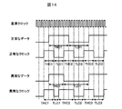
図14は正常時のクロック及びデータと異常時のクロック及びデータのパルス幅測定結果についてのタイミング図の例である。この例では、データに関しては正常時のTHD1よりも異常時のTHD1のほうがパルス幅測定結果が短くなり、正常時のTLD1よりも異常時のTLD1のほうがパルス幅測定結果が長くなり、アラームあるいはワーニングを出力する。クロックに関しては正常時のTLC1よりも異常時のTLC1のほうがパルス幅測定結果が短くなり、正常時のTHC2よりも異常時のTHC2のほうがパルス幅測定結果が長くなり、アラームあるいはワーニングを出力する。 FIG. 14 is an example of a timing diagram for the pulse width measurement results of the normal clock and data and the abnormal clock and data. In this example, regarding the data, the pulse width measurement result is shorter in the THD1 in the abnormal state than in the THD1 in the normal state, and the pulse width measurement result is longer in the TLD1 in the abnormal state than in the TLD1 in the normal state. Is output. As for the clock, the pulse width measurement result is shorter in the abnormal TLC1 than in the normal TLC1, and the pulse width measurement result is longer in the abnormal THC2 than in the normal THC2, and an alarm or warning is output.
図15は正常時のクロック及びデータと異常時のクロック及びデータの位相差測定結果についてのタイミング図の例である。この例では、正常時のPL1よりも異常時のPL1のほうが位相差測定結果が長くなり、アラームあるいはワーニングを出力する。 FIG. 15 is an example of a timing diagram for the phase difference measurement result between the normal clock and data and the abnormal clock and data. In this example, the phase difference measurement result is longer in PL1 at the time of abnormality than PL1 at the time of normality, and an alarm or warning is output.
本発明のモータ制御装置は、クロック信号及びデジタルデータ信号のパルス幅を計測し、クロック信号とデジタルデータ信号の位相差を測定し、ノイズ発生頻度を検知することができ、クロック数測定異常、パルス幅測定異常、位相差測定異常が発生する頻度を計測し、ノイズ発生の頻度や大きさを検知することで、ノイズ源を特定することができる。 The motor control device of the present invention can measure the pulse width of the clock signal and the digital data signal, measure the phase difference between the clock signal and the digital data signal, and detect the noise occurrence frequency. By measuring the frequency of occurrence of width measurement abnormality and phase difference measurement abnormality and detecting the frequency and magnitude of noise generation, the noise source can be specified.
また、本発明のモータ制御装置は、デジタルフィルタの前後において一定時間中のクロック数を測定し、デジタルフィルタの前後の一定時間中のクロック数を比較することデジタルフィルタの効果を知ることができ、検出したノイズレベルに応じて、前記電流検出回路内のデジタルフィルタの段数やフィルタ周波数の変更を行い、検出したノイズのレベルに応じてデジタルフィルタの段数やフィルタ周波数の変更を行い、それに応じて制御ゲインを最適値に自動調整することができる。 Further, the motor control device of the present invention can know the effect of the digital filter by measuring the number of clocks in a certain time before and after the digital filter and comparing the number of clocks in the certain time before and after the digital filter, Change the number of digital filter stages and filter frequency in the current detection circuit according to the detected noise level, change the number of digital filter stages and filter frequency according to the detected noise level, and control accordingly Gain can be automatically adjusted to the optimum value.
なお、本発明は上記した実施例に限定されるものではなく、様々な変形例が含まれる。例えば、上記した実施例は本発明を分かりやすく説明するために詳細に説明したものであり、必ずしも説明した全ての構成を備えるものに限定されるものではない。また、ある実施例の構成の一部を他の実施例の構成に置き換えることが可能であり、また、ある実施例の構成に他の実施例の構成を加えることも可能である。また、各実施例の構成の一部について、他の構成の追加・削除・置換をすることが可能である。 In addition, this invention is not limited to an above-described Example, Various modifications are included. For example, the above-described embodiments have been described in detail for easy understanding of the present invention, and are not necessarily limited to those having all the configurations described. In addition, a part of the configuration of a certain embodiment can be replaced with the configuration of another embodiment, and the configuration of another embodiment can be added to the configuration of a certain embodiment. Further, it is possible to add, delete, and replace other configurations for a part of the configuration of each embodiment.
また、上記の各構成、機能、処理部、処理手段等は、それらの一部又は全部を、例えば集積回路で設計する等によりハードウェアで実現してもよい。また、上記の各構成、機能等は、プロセッサがそれぞれの機能を実現するプログラムを解釈し、実行することによりソフトウェアで実現してもよい。各機能を実現するプログラム、テーブル、ファイル等の情報は、メモリや、ハードディスク、SSD、等の記録装置、または、ICカード、SDカード、DVD等の記録媒体に置くことができる。 Each of the above-described configurations, functions, processing units, processing means, and the like may be realized by hardware by designing a part or all of them with, for example, an integrated circuit. Each of the above-described configurations, functions, and the like may be realized by software by interpreting and executing a program that realizes each function by the processor. Information such as programs, tables, and files for realizing each function can be stored in a recording device such as a memory, a hard disk, or an SSD, or a recording medium such as an IC card, an SD card, or a DVD.
また、制御線や情報線は説明上必要と考えられるものを示しており、製品上必ずしも全ての制御線や情報線を示しているとは限らない。実際には殆ど全ての構成が相互に接続されていると考えてもよい。 Further, the control lines and information lines indicate what is considered necessary for the explanation, and not all the control lines and information lines on the product are necessarily shown. Actually, it may be considered that almost all the components are connected to each other.
1 インバータ回路
2 ベースドライブ回路
3 制御回路
4 電流検出回路
5 AD変換器
6 AD変換器
7 サーボモータ
8 エンコーダ
9 AD変換器
10 電流検出回路
11 デジタルフィルタ
12 デジタルフィルタ
13 クロック数測定回路
14 クロック・データパルス幅測定回路
15 クロック・データ位相差測定回路
16 シリアル−パラレル変換回路
17 判定回路
18 制御回路
DESCRIPTION OF
Claims (10)
前記インバータ回路からサーボモータに供給される3相交流出力の電流を検出し、AD変換器によりアナログ信号からデジタル信号に変換されたデジタルデータを検出する電流検出装置と、を備えたモータ制御装置において、
前記電流検出装置に前記デジタルデータ信号と前記AD変換器のクロック信号とが入力され、前記クロック信号に基づいてノイズレベルを検出することを特徴とするモータ制御装置。 An inverter circuit that performs a switching operation by a gate drive signal supplied from a control circuit via a base drive circuit, converts a DC voltage, and outputs three-phase AC power;
In a motor control device comprising: a current detection device that detects a current of a three-phase AC output supplied from the inverter circuit to a servomotor and detects digital data converted from an analog signal to a digital signal by an AD converter; ,
The motor control device, wherein the digital data signal and the clock signal of the AD converter are input to the current detection device, and a noise level is detected based on the clock signal.
前記クロック信号の一定時間中のクロック数の測定を行うことでノイズレベルを検出することを特徴とするモータ制御装置。 The motor control device according to claim 1,
A motor control device for detecting a noise level by measuring the number of clocks of the clock signal during a predetermined time.
前記AD変換器から出力された前記クロック信号及び前記デジタルデータ信号がHレベルである時間、Lレベルである時間をそれぞれ測定することにより前記クロック信号及び前記デジタルデータ信号のパルス幅を計測することを特徴とするモータ制御装置。 The motor control device according to claim 1,
Measuring the pulse width of the clock signal and the digital data signal by measuring the time when the clock signal and the digital data signal output from the AD converter are at the H level and the time when the digital data signal is at the L level, respectively. A motor control device.
前記AD変換器から出力された前記クロック信号と前記デジタルデータ信号の位相差を測定することを特徴とするモータ制御装置。 The motor control device according to claim 1,
A motor control device that measures a phase difference between the clock signal output from the AD converter and the digital data signal.
クロック数測定時間を変更することにより、ノイズ発生頻度を検知することを特徴とするモータ制御装置。 The motor control device according to claim 1,
A motor control device that detects a frequency of noise occurrence by changing a clock number measurement time.
クロック数測定異常、パルス幅測定異常、位相差測定異常が発生する頻度を計測し、ノイズ発生の頻度や大きさを検知することで、ノイズ源を特定することを特徴とするモータ制御装置。 The motor control device according to claim 1,
A motor control device characterized by measuring the frequency of occurrence of clock number measurement abnormality, pulse width measurement abnormality, and phase difference measurement abnormality, and identifying the noise source by detecting the frequency and magnitude of noise generation.
前記電流検出装置は、前記クロック信号のノイズを除去するデジタルフィルタを備えており、前記デジタルフィルタの前後において一定時間中のクロック数を測定し、前記デジタルフィルタの前後の一定時間中のクロック数を比較することを特徴とするモータ制御装置。 The motor control device according to claim 2,
The current detection device includes a digital filter that removes noise of the clock signal, measures the number of clocks in a certain time before and after the digital filter, and determines the number of clocks in a certain time before and after the digital filter. A motor controller characterized by comparing.
前記デジタルフィルタの前後において、一定時間中のクロック数を測定し比較することで、前記デジタルフィルタの効果を知ることができることを特徴とするモータ制御装置。 The motor control device according to claim 7,
The motor control device characterized in that the effect of the digital filter can be known by measuring and comparing the number of clocks in a certain time before and after the digital filter.
検出したノイズレベルに応じて、前記電流検出装置内のデジタルフィルタの段数やフィルタ周波数の変更を行うことを特徴とするモータ制御装置。 The motor control device according to claim 7,
A motor control device that changes the number of stages of digital filters and the filter frequency in the current detection device in accordance with the detected noise level.
検出したノイズのレベルに応じて、デジタルフィルタの段数やフィルタ周波数の変更を行い、それに応じて制御ゲインを最適値に自動調整することを特徴とするモータ制御装置。 The motor control device according to claim 9,
A motor control device, wherein the number of stages of the digital filter and the filter frequency are changed according to the detected noise level, and the control gain is automatically adjusted to an optimum value accordingly.
Priority Applications (1)
| Application Number | Priority Date | Filing Date | Title |
|---|---|---|---|
| JP2010251915A JP5523286B2 (en) | 2010-11-10 | 2010-11-10 | Motor control device |
Applications Claiming Priority (1)
| Application Number | Priority Date | Filing Date | Title |
|---|---|---|---|
| JP2010251915A JP5523286B2 (en) | 2010-11-10 | 2010-11-10 | Motor control device |
Publications (2)
| Publication Number | Publication Date |
|---|---|
| JP2012105455A true JP2012105455A (en) | 2012-05-31 |
| JP5523286B2 JP5523286B2 (en) | 2014-06-18 |
Family
ID=46395180
Family Applications (1)
| Application Number | Title | Priority Date | Filing Date |
|---|---|---|---|
| JP2010251915A Expired - Fee Related JP5523286B2 (en) | 2010-11-10 | 2010-11-10 | Motor control device |
Country Status (1)
| Country | Link |
|---|---|
| JP (1) | JP5523286B2 (en) |
Cited By (2)
| Publication number | Priority date | Publication date | Assignee | Title |
|---|---|---|---|---|
| US9673794B2 (en) | 2014-06-02 | 2017-06-06 | Mitsubishi Electric Corporation | Noise analysis apparatus, electronic device, and noise-source identification system |
| US11159116B2 (en) | 2018-01-29 | 2021-10-26 | Omron Corporation | Motor control device and motor control system |
Citations (5)
| Publication number | Priority date | Publication date | Assignee | Title |
|---|---|---|---|---|
| JPH11122308A (en) * | 1997-10-09 | 1999-04-30 | Nec Eng Ltd | Overflow and underflow detection circuit |
| JP2000083950A (en) * | 1998-09-11 | 2000-03-28 | Hitachi Medical Corp | Medical x-ray device |
| JP2003057270A (en) * | 2001-08-10 | 2003-02-26 | Advantest Corp | Voltage-applied current measuring apparatus and semiconductor tester |
| JP2003148997A (en) * | 2001-11-19 | 2003-05-21 | Fuji Electric Co Ltd | Information processing / control device for improving noise immunity and noise immunity detecting means thereof |
| JP2010004696A (en) * | 2008-06-23 | 2010-01-07 | Panasonic Corp | Device for estimating output, motor controller using it and motor control system |
-
2010
- 2010-11-10 JP JP2010251915A patent/JP5523286B2/en not_active Expired - Fee Related
Patent Citations (5)
| Publication number | Priority date | Publication date | Assignee | Title |
|---|---|---|---|---|
| JPH11122308A (en) * | 1997-10-09 | 1999-04-30 | Nec Eng Ltd | Overflow and underflow detection circuit |
| JP2000083950A (en) * | 1998-09-11 | 2000-03-28 | Hitachi Medical Corp | Medical x-ray device |
| JP2003057270A (en) * | 2001-08-10 | 2003-02-26 | Advantest Corp | Voltage-applied current measuring apparatus and semiconductor tester |
| JP2003148997A (en) * | 2001-11-19 | 2003-05-21 | Fuji Electric Co Ltd | Information processing / control device for improving noise immunity and noise immunity detecting means thereof |
| JP2010004696A (en) * | 2008-06-23 | 2010-01-07 | Panasonic Corp | Device for estimating output, motor controller using it and motor control system |
Cited By (2)
| Publication number | Priority date | Publication date | Assignee | Title |
|---|---|---|---|---|
| US9673794B2 (en) | 2014-06-02 | 2017-06-06 | Mitsubishi Electric Corporation | Noise analysis apparatus, electronic device, and noise-source identification system |
| US11159116B2 (en) | 2018-01-29 | 2021-10-26 | Omron Corporation | Motor control device and motor control system |
Also Published As
| Publication number | Publication date |
|---|---|
| JP5523286B2 (en) | 2014-06-18 |
Similar Documents
| Publication | Publication Date | Title |
|---|---|---|
| US9007056B2 (en) | Monitoring device and monitoring method for rotary encoder | |
| JP5523286B2 (en) | Motor control device | |
| US8400097B2 (en) | Pulse period measurement method | |
| CN101750198B (en) | Method for measuring corresponding phase positions of vibration signals of different measuring points of rotary machine | |
| CN202770963U (en) | Proximity switch detection apparatus | |
| CN112067912B (en) | Open-phase detection method, electronic equipment and storage medium | |
| CN103575312A (en) | Jitter elimination method of incremental photoelectric encoder for photoelectric rotating table | |
| CN201051134Y (en) | Acentric switch break rotation speed detector | |
| CN101387692A (en) | Power converter with degraded component warning | |
| CN105572411A (en) | Differential type anti-strong-interference real time velometer based on Arduino, and control method thereof | |
| KR940012361A (en) | Data detection level adjusting circuit and method of disk drive | |
| CN107340752B (en) | Machine tool control device | |
| CN102495225B (en) | Device and method for measuring rotating speed of steam turbine | |
| CN102392816B (en) | FPGA (field programmable gate array) based system and method for measuring speed of fan | |
| WO2015186175A1 (en) | Noise analysis device, electronic device, and noise source specification system | |
| US7656625B2 (en) | Disc apparatus | |
| JP5299844B2 (en) | Speed monitoring device | |
| CN105842473A (en) | Method and system for speed measurement of rotary encoder | |
| KR101531340B1 (en) | Servo motor control system | |
| CN216581215U (en) | Transparent paper disc diameter detection device of FOCKE401 small box transparent paper packaging machine | |
| CN116147911B (en) | Device and method for detecting abnormality of power transmission mechanism | |
| JP5539090B2 (en) | Encoder with noise level detection function | |
| US11762791B1 (en) | System, method, and non-transitory computer readable medium for detecting baseboard management controller | |
| JP5593256B2 (en) | Motor control device | |
| US20240193027A1 (en) | Enhanced transducer fault detection |
Legal Events
| Date | Code | Title | Description |
|---|---|---|---|
| A621 | Written request for application examination |
Free format text: JAPANESE INTERMEDIATE CODE: A621 Effective date: 20121108 |
|
| A977 | Report on retrieval |
Free format text: JAPANESE INTERMEDIATE CODE: A971007 Effective date: 20131224 |
|
| A131 | Notification of reasons for refusal |
Free format text: JAPANESE INTERMEDIATE CODE: A131 Effective date: 20140107 |
|
| A521 | Request for written amendment filed |
Free format text: JAPANESE INTERMEDIATE CODE: A523 Effective date: 20140303 |
|
| TRDD | Decision of grant or rejection written | ||
| A01 | Written decision to grant a patent or to grant a registration (utility model) |
Free format text: JAPANESE INTERMEDIATE CODE: A01 Effective date: 20140318 |
|
| A61 | First payment of annual fees (during grant procedure) |
Free format text: JAPANESE INTERMEDIATE CODE: A61 Effective date: 20140408 |
|
| R150 | Certificate of patent or registration of utility model |
Ref document number: 5523286 Country of ref document: JP Free format text: JAPANESE INTERMEDIATE CODE: R150 |
|
| LAPS | Cancellation because of no payment of annual fees |