JP2012105486A - Electric vehicle - Google Patents
Electric vehicle Download PDFInfo
- Publication number
- JP2012105486A JP2012105486A JP2010253224A JP2010253224A JP2012105486A JP 2012105486 A JP2012105486 A JP 2012105486A JP 2010253224 A JP2010253224 A JP 2010253224A JP 2010253224 A JP2010253224 A JP 2010253224A JP 2012105486 A JP2012105486 A JP 2012105486A
- Authority
- JP
- Japan
- Prior art keywords
- motor
- road surface
- electric vehicle
- determination unit
- torque
- Prior art date
- Legal status (The legal status is an assumption and is not a legal conclusion. Google has not performed a legal analysis and makes no representation as to the accuracy of the status listed.)
- Granted
Links
Images


Classifications
-
- Y—GENERAL TAGGING OF NEW TECHNOLOGICAL DEVELOPMENTS; GENERAL TAGGING OF CROSS-SECTIONAL TECHNOLOGIES SPANNING OVER SEVERAL SECTIONS OF THE IPC; TECHNICAL SUBJECTS COVERED BY FORMER USPC CROSS-REFERENCE ART COLLECTIONS [XRACs] AND DIGESTS
- Y02—TECHNOLOGIES OR APPLICATIONS FOR MITIGATION OR ADAPTATION AGAINST CLIMATE CHANGE
- Y02T—CLIMATE CHANGE MITIGATION TECHNOLOGIES RELATED TO TRANSPORTATION
- Y02T10/00—Road transport of goods or passengers
- Y02T10/60—Other road transportation technologies with climate change mitigation effect
- Y02T10/72—Electric energy management in electromobility
Landscapes
- Regulating Braking Force (AREA)
- Electric Propulsion And Braking For Vehicles (AREA)
Abstract
Description
本発明は、電動車両にかかるものである。 The present invention relates to an electric vehicle.
近年、燃費節減、エミッション低減等のために、いわゆるアイドルストップ制御システム(エンジン自動停止始動制御システム)を搭載した車両が注目されている。従来の一般的なアイドルストップ制御システムは、運転者が車両を停車させたときに燃料噴射を停止してエンジンを自動的に停止させ、その後、運転者がブレーキ解除操作やアクセル踏込み操作等の車両を発進操作を行ったときに自動的にモータに通電してエンジンを再始動させるように構成している(例えば、特許文献1参照)。 In recent years, a vehicle equipped with a so-called idle stop control system (engine automatic stop / start control system) has been attracting attention in order to reduce fuel consumption and emissions. The conventional general idle stop control system stops fuel injection when the driver stops the vehicle and automatically stops the engine, and then the driver performs vehicle such as brake release operation or accelerator depression operation. When the start operation is performed, the motor is automatically energized to restart the engine (see, for example, Patent Document 1).
ところで、近年では、二酸化炭素若しくは窒素酸化物に係る排出量の削減要請の高まりなどを背景として、内燃機関に代わり、電動機を動力源として搭載した電気自動車が急速に普及してきている。 By the way, in recent years, an electric vehicle equipped with an electric motor as a power source instead of an internal combustion engine has been rapidly spread against the background of an increasing demand for reduction of emissions related to carbon dioxide or nitrogen oxides.
このような電気自動車においても、アイドルストップ制御システムのように、運転者が車両を停車させたときに一時的にモータへの電力供給を自動的に停止させ、その後、運転者がブレーキ解除操作やアクセル踏込み操作等の車両の発進操作を行ったときに自動的にモータに通電して電力消費を抑制させることが考えられる。 Even in such an electric vehicle, like the idle stop control system, when the driver stops the vehicle, the electric power supply to the motor is automatically stopped temporarily, and then the driver performs a brake release operation or It is conceivable that the motor is automatically energized to suppress power consumption when a start operation of the vehicle such as an accelerator operation is performed.
しかしながら、車両が停止した場合に、次に車両を発進させるためにブレーキペダルからアクセルペダルへの踏み換えが行われるが、この踏み換えに際して、上り坂においては、アクセルペダルを踏んだ場合に、所望のトルクを得ることができないことがあり、また、平坦路や特に下り坂においては、アクセルペダルを踏んだ場合に、所望以上のトルクを得てしまい、乗り心地に影響を与えることがあるという問題がある。 However, when the vehicle stops, the brake pedal is changed to the accelerator pedal to start the vehicle next. When the accelerator pedal is depressed on the uphill, Torque may not be able to be obtained, and on flat roads, especially on downhills, when the accelerator pedal is depressed, more torque than desired may be obtained, which may affect riding comfort. There is.
そこで、本発明の課題は、上記従来技術の問題点を解決することにあり、再始動時において安定したトルク出力を得ることができる電動車両を提供しようとするものである。 Accordingly, an object of the present invention is to solve the above-described problems of the prior art, and to provide an electric vehicle capable of obtaining a stable torque output at the time of restart.
本発明の電動車両は、車両駆動用のモータで走行する電動車両において、前記モータの作動中に前記モータの停止条件が成立した場合には前記モータを自動的に停止させると共に、前記停止条件が解除された場合に前記モータを再始動させるモータコントロール部と、前記停止条件が解除されてから所定時間までの前記モータの回転速度を積算して積算値を算出し、前記積算値に基づいて路面の傾斜状態を判定する路面傾斜判定部とを備えることを特徴とする。 The electric vehicle according to the present invention is an electric vehicle that is driven by a motor for driving a vehicle, and when the motor stop condition is satisfied during operation of the motor, the motor is automatically stopped and the stop condition is A motor control unit that restarts the motor when released, and calculates an integrated value by integrating the rotational speed of the motor up to a predetermined time after the stop condition is canceled, and the road surface based on the integrated value And a road surface inclination determination unit for determining the inclination state of the vehicle.
本発明によれば、路面傾斜判定部を備えることで、停止条件が解除された際における路面の傾斜状態を判定する。この場合に、モータ回転速度を積算した積算値に基づいて判断することで、より正確に路面状態を判定することが可能である。 According to the present invention, by including the road surface inclination determination unit, the road surface inclination state when the stop condition is canceled is determined. In this case, it is possible to determine the road surface state more accurately by making a determination based on the integrated value obtained by integrating the motor rotation speed.
ここで、前記モータコントロール部は、ブレーキの油圧が所定値未満であるとき、前記停止条件が解除されたと判断することが好ましい。このように、モータコントロール部は、ブレーキの油圧が所定値未満であるとき、前記停止条件が解除されたと判断する。ブレーキの油圧が所定値未満であるかどうかを判断することで、簡易に、かつ、運転者の意志を適切にとらえて停止条件を解除することが可能である。 Here, it is preferable that the motor control unit determines that the stop condition is released when the hydraulic pressure of the brake is less than a predetermined value. Thus, the motor control unit determines that the stop condition is released when the brake hydraulic pressure is less than a predetermined value. By determining whether or not the brake hydraulic pressure is less than a predetermined value, it is possible to easily and appropriately grasp the driver's will to cancel the stop condition.
また、前記路面傾斜判定部は、前記モータコントロール部は、クリープトルクを発生させるクリープトルク発生手段を有し、前記所定時間とは、前記クリープトルク発生手段がクリープトルクの発生を開始させる時間であることが好ましい。これにより、路面傾斜判定部は、停止条件が解除されてからクリープトルクが発生するまでのモータ回転速度の積算値に基づいて傾斜状態を判断する。モータ回転に重力のみが影響する期間で傾斜状態を判断するので、更に正確な傾斜状態の判定が可能となる。 In addition, the road surface inclination determination unit includes a creep torque generation unit that generates creep torque, and the predetermined time is a time for the creep torque generation unit to start generating creep torque. It is preferable. Thus, the road surface inclination determination unit determines the inclination state based on the integrated value of the motor rotation speed from when the stop condition is canceled until creep torque is generated. Since the tilt state is determined in a period in which only the gravity affects the motor rotation, it is possible to determine the tilt state more accurately.
前記路面傾斜判定部が、前記積算値が大きいほど傾斜の勾配が大きいと判定することが好ましい。即ち、路面傾斜判定部は、積算値が大きいほど傾斜の勾配が大きいと判定するので、傾斜状態と共に、傾斜の勾配について判定することができる。 It is preferable that the road surface inclination determination unit determines that the inclination gradient is larger as the integrated value is larger. That is, since the road surface inclination determination unit determines that the inclination gradient is larger as the integrated value is larger, it is possible to determine the inclination inclination as well as the inclination state.
前記モータコントロール部は、前記モータを再始動させる際、判定された前記傾斜状態に応じて前記モータの出力トルクを制御することが好ましい。モータコントロール部は、モータを再始動させる際、路面傾斜判定部が判定した傾斜状態に応じてモータのトルク出力を制御する。傾斜状態に合わせてトルクを変更することで、再始動時において安定したトルク出力を得ることができる。また傾斜の勾配に合わせて詳細にトルクを変更することができ、再始動時においてより安定したトルク出力を得ることが可能である。 The motor control unit preferably controls the output torque of the motor according to the determined inclination state when the motor is restarted. The motor control unit controls the torque output of the motor according to the inclination state determined by the road surface inclination determination unit when the motor is restarted. By changing the torque in accordance with the inclined state, a stable torque output can be obtained at the time of restart. Further, the torque can be changed in detail according to the gradient of the inclination, and a more stable torque output can be obtained at the time of restart.
本発明の電動車両によれば、再始動時において安定したトルク出力を得ることができるという優れた効果を奏し得る。 According to the electric vehicle of the present invention, it is possible to achieve an excellent effect that a stable torque output can be obtained at the time of restart.
以下、本発明の実施形態について図1〜図6を用いて説明する。 Hereinafter, embodiments of the present invention will be described with reference to FIGS.
図1に示すように、電動車両の一例である電気自動車1は、モータ2を備えており、このモータ2は駆動輪(図示せず)に接続されている。即ち、電気自動車1は、モータ2を駆動源として走行可能に構成されている。また電気自動車1には、外部から電力供給可能とされた二次電池であるバッテリー3が搭載されている。バッテリー3はモータ2に電気的に接続されている。モータ2はこのバッテリー3から供給される電力によって駆動される。
As shown in FIG. 1, an
また、電気自動車1は、車両の統合制御を行うECU4を備えている。ECU4は、電気自動車1に設けられた各種センサからの検出結果に基づいてバッテリー3の充電制御やモータ2の駆動制御等を実行する。
The
本実施形態では、ECU4は、MCU(モータコントロール部)10を備えている。MCU10は、モータ2の駆動制御を行うためのコントロールユニットである。
In the present embodiment, the ECU 4 includes an MCU (motor control unit) 10. The MCU 10 is a control unit for performing drive control of the
また、ECU4は、停止・再始動判定部11を備える。この停止・再始動判定部11は、運転者が車両を停車させたときに一時的にモータ2への電力供給を自動的に停止させ、その後、運転者がブレーキ解除操作やアクセル踏込み操作等の車両の発進操作を行ったときに自動的に停止条件を解除し、モータ2に通電して電力消費を抑制させるためのものである。即ち、停止・再始動判定部11は、モータ2への電力供給の停止条件が成立するかどうか、及びこの停止条件が解除されるかどうかを判定する。停止・再始動判定部11がモータ2の停止条件が成立したと判定すると、ECU4はMCU10への電力供給を停止する。MCU10への電力供給の停止に伴い、モータ2の通電も停止され、モータ2の作動も停止される。
Further, the ECU 4 includes a stop /
そして、停止・再始動判定部11はその後も例えば所定時間毎に判定を続けて、運転者が再び車両を発進させようとしてモータ2の停止条件が解除されたと判定すると、ECU4はMCU10を再始動させてモータ2への電力供給を再開し、モータ2を再始動させるように駆動制御する。このようにして、停止・再始動判定部11を設けることで、電気自動車1では、所定条件下でモータ2への電力供給を自動的に停止されると共に、所定条件下で自動的に停止条件が解除され、モータ2に通電して電力消費を抑制させている。
Then, the stop /
停止・再始動判定部11における判定について詳細に説明する。停止・再始動判定部11は、ECU4が常に取得している変数から、モータ2の停止条件が成立しているかどうかを判定する。
The determination in the stop /
本実施形態では、モータ2の停止条件としては、ブレーキの油圧が所定値以上であるか、アクセルの開度が全閉であるか、車速が0であるか、シフトレバーのポジションがDレンジであるか、モータ2のトルクフィードバックが所定値以下であるかどうかが挙げられる。これらは、ブレーキの油圧の検出手段であるブレーキ油圧検出部5、アクセル開度の検出手段であるアクセル検出部6、車速の検出手段である車速検出部7、シフトレバーのポジションを検出するポジション検出部8、及びモータ2のトルク検出手段であるトルク検出部9から、検出結果が常にECU4へ出力されている。停止・再始動判定部11では、これらの検出結果から、停止条件が成立している場合、つまり、ブレーキ油圧検出部5で検出された油圧値が所定値以上であり、アクセル検出部6で検出されたアクセル開度が全閉であり、車速検出部7で検出された車速が0であり、ポジション検出部8で検出されたシフトレバーのポジションがDレンジであり、トルク検出部9で検出されたフィードバックトルク値が所定値以下である場合には、停止・再始動判定部11は電気自動車1の停止条件が成立したと判定する。
In the present embodiment, the stop condition of the
停止・再始動判定部11が停止条件成立を判定すると、ECU4はMCU10への電力供給を停止する。MCU10への電力供給の停止に伴い、モータ2の通電も停止され、モータ2の作動も停止され、電力消費量を抑制する。
When the stop /
停止・再始動判定部11が停止条件成立を判定した後に、停止条件が不成立、即ち停止条件が解除となるとECU4はMCU10への電力供給を再始動してモータ2を始動させる。このような停止条件が不成立、即ち停止条件が解除される場合とは、上述した停止条件が一つでも満たされない場合であるが、本実施形態では、特にブレーキの油圧が所定値未満であるかどうかで判断する。これは、電気自動車では通常停止時には運転者はブレーキを踏み続ける必要があり、ブレーキを踏んでいない場合には、運転者に電気自動車1を駆動させる意志があると最も簡易に、かつ正確に判断できるからである。
After the stop /
従って、本実施形態では、停止・再始動判定部11がブレーキの油圧が所定値未満であるのを検出し、停止条件が解除されたことを判定した場合にはECU4はMCU10への電力供給を再始動してモータ2を始動させる。
Therefore, in the present embodiment, when the stop /
この場合に、電気自動車1が上り坂にいるとすれば、運転者が電気自動車1を進行させようとしてブレーキを解除してアクセルを踏込むまでの非常に短い時間に、電気自動車1が後退したり、また、アクセルを踏み込んでもすぐには所望の出力を得ることができない場合が考えられるので、これを防止する必要がある。また、電気自動車1が平坦路、もしくは下り坂にいる場合には、運転者が電気自動車1を進行させようとしてブレーキを解除してアクセルを踏込むと、所望以上の出力を得てしまい、トルクショックが発生して乗り心地に影響を及ぼすことが考えられるので、これを防止する必要がある。
In this case, if the
そこで、本実施形態においては、ECU4は、電気自動車1の路面状態を判定する路面傾斜判定部12を備える。路面傾斜判定部12が電気自動車1の路面が上り坂であると判定すれば、ECU4は、モータトルクが通常値よりも大きくなるようにモータ2を駆動制御し、路面傾斜判定部12が電気自動車1の路面が下り坂であると判定すれば、ECU4は、モータトルクが通常値よりも小さくなるようにモータ2を駆動制御する。これにより、上り坂でもすぐに所望の出力を得ることができると同時に、下り坂でも所望の出力を得て乗り心地を悪化させることがなく、安定した走行を実現できる。
Therefore, in the present embodiment, the ECU 4 includes a road surface
具体的に、路面傾斜判定部12について図2を用いて説明する。
Specifically, the road surface
路面傾斜判定部12は、モータ回転速度積算部21と、クリープトルク判定部22と、路面判定部23と、傾斜状態判定部24とを備える。
The road surface
停止・再始動判定部11が、ブレーキの油圧が所定値以下であり停止条件が解除されたことを判定すると、MCU10の再始動を示す信号を入力する。停止・再始動判定部11は、この再始動を示す信号をMCU10に入力すると共に、路面傾斜判定部12に判定開始を示す信号を入力する。
When the stop /
路面傾斜判定部12は、判定開始を示す信号が入力されると、停止条件が解除されてから積算値を検出するのに十分な所定時間が経過したものとして、モータ回転速度積算部21で一定時間毎に取得されていたモータ2のモータ回転速度を積算して、積算値(積分値)を算出する。なお、モータ回転速度は、ECU4がモータ2に設けられた検出手段から取得される。
When a signal indicating the determination start is input, the road surface
このモータ回転速度の積算値が大きいほど、傾斜の勾配が大きい。この累積値の積算は、後述するようにクリープトルクの発生を示す判定信号が入力されるまで続く。即ち、モータ回転速度積算部21では、一定時間おきにECU4が取得するモータ回転速度を記録して加算していく。
The greater the integrated value of the motor rotation speed, the greater the gradient of the inclination. The accumulation of the accumulated values continues until a determination signal indicating the generation of creep torque is input as will be described later. That is, the motor rotation
また、路面傾斜判定部12は、判定開始を示す信号が入力されると、クリープトルク判定部22が、MCU10の再起動が完了してクリープトルクが発生しているかどうかを判定する。このクリープトルクは、MCU10が有するクリープトルク発生手段(図示せず)により発生する。クリープトルクの発生は、モータ2のトルク検出手段であるトルク検出部9からECU4が取得するトルク値により判定される。
Further, when a signal indicating the start of determination is input, the road surface
そして、クリープトルク判定部22が、クリープトルクの発生を判定すると、発生を示す判定信号をモータ回転速度積算部21及び路面判定部23とに入力する。
When the creep
モータ回転速度積算部21は、クリープトルクの発生を示す判定信号が入力されると、モータ回転速度の積算値の算出を停止する。即ち、モータ回転速度積算部21は、クリープトルクの発生を示す判定信号が入力されるとMCU10の停止条件が解除されてから所定時間が経過したものとして、そのときまでのモータ回転速度の積算値の合計を算出するのである。そして、モータ回転速度積算部21は、積算値を示す信号を傾斜状態判定部24に送出する。
When the determination signal indicating the generation of creep torque is input, the motor rotation
路面判定部23は、クリープトルクの発生を示す判定信号が入力されると、その時のモータ回転速度が正であるか、負であるかを判断して、路面が上り坂であるか、下り坂であるかどうかを判断する。つまり、モータ回転速度が負である場合には、路面は上り坂であり、モータ回転速度が正である場合には、路面は下り坂である。そして、路面判定部23は、路面状態を示す信号を傾斜状態判定部24に送出する。
When a determination signal indicating the generation of creep torque is input, the road
傾斜状態判定部24は、モータ回転速度積算部21からの積算値を示す信号と、傾斜状態判定部24からの路面状態を示す信号とから、路面の勾配の程度、即ち、どのくらいの勾配の上り坂、もしくは下り坂や平坦地なのかを判定する。
The inclination
この場合に、傾斜状態判定部24は、積算値に応じて路面の勾配を判定するために、例えばマップを有しており、このマップから路面の勾配を判定する。例えば、積算値がq1〜q2(q1<q2)の間では、路面の勾配が小さく、積算値がq2〜q3の間では、路面の勾配は大きい、というように積算値がマップの複数の値のどの範囲にあるかによって路面の勾配を設定する。
In this case, the inclination
このようにして、積算値を示す信号が、積算値がq2よりも小さい値であり、かつ、路面状態を示す信号が路面が上り坂であることを示していれば、傾斜状態判定部24は、路面が勾配の小さな上り坂であることを判定する。
In this way, if the signal indicating the integrated value is a value smaller than q2 and the signal indicating the road surface state indicates that the road surface is uphill, the inclination
その後、ECU4は、傾斜状態判定部24の判定結果に基づいて、所望の出力を得ることができるトルクを設定し、これをMCU10に送出する。MCU10は、この設定されたトルクを出力できるようにモータ2を駆動制御する。例えば、上述のように傾斜状態判定部24が路面は勾配の小さな上り坂であることを判定した場合には、ECU4は、トルクを上り坂時の標準値よりも大きくするように設定してMCU10に送出する。この場合、例えばECU4は、これにより、上り坂におけるトルク不足を抑制して、電気自動車1は乗り心地が向上し、かつ、安定した走行が可能となる。
Thereafter, the ECU 4 sets a torque capable of obtaining a desired output based on the determination result of the inclination
本実施形態では、ECU4がMCU10への再始動を示す信号を送出した後MCU10が再始動するまでの間に、路面傾斜判定部12により路面状態を判定し、これに基づいてモータ2のトルクを設定するように構成されていることから、再始動時において安定したトルク出力を得ることができる。
In this embodiment, after the ECU 4 sends a signal indicating restart to the
また、本実施形態においては、路面傾斜判定部12では、積算値とモータ回転速度の正負との両方から判断することで、誤作動を防止している。つまり、例えばモータ回転方向やタイヤの回転方向のみで路面状態を判断する場合には、路面に凹凸があるだけで回転して坂ではないのに坂であると誤判定してしまう場合がある。しかしながら、本実施形態においては、モータ回転速度のようなモータの回転状況を示す指標値を積算した積算値から判定しているので、例えば積算値が0であるのに回転速度のみ負であるとすれば、誤作動であると判定できるので、より判断を正確に行うことが可能である。
Moreover, in this embodiment, the road surface
本実施形態について、図3〜図6を用いてより詳細に説明する。 This embodiment will be described in more detail with reference to FIGS.
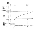
図3は、路面が上り坂である場合に本実施形態における制御を用いた場合の制御結果を示すものである。なお、図3〜図6において、横軸はそれぞれ時間tを示しており、縦軸は、それぞれブレーキ油圧検出部で検出されるブレーキ油圧(MPa)、トルク検出部で検出されるトルク値(N・m)、ECUがモータに設けられた検出手段から得られるモータ回転速度(rpm)を示している。 FIG. 3 shows a control result when the control according to this embodiment is used when the road surface is an uphill. 3 to 6, the horizontal axis represents time t, and the vertical axis represents the brake hydraulic pressure (MPa) detected by the brake hydraulic pressure detection unit and the torque value (N) detected by the torque detection unit, respectively. M) indicates the motor rotation speed (rpm) obtained by the ECU from the detection means provided in the motor.
まず、t=t1では、ブレーキの油圧が所定値以上であるので、電気自動車は停止しており、ここでは図示しないが他の停止条件が成立していて、MCUはスリープ状態にある。なお、電気自動車1は停止状態であるので、トルクもモータ回転速度も0である。
First, at t = t1, since the brake hydraulic pressure is equal to or higher than a predetermined value, the electric vehicle is stopped. Although not shown here, other stop conditions are satisfied, and the MCU is in the sleep state. Since the
そして、t=t2前後から、運転者が徐々に足をブレーキから離すことによりブレーキの油圧が徐々に下降する。なお、電気自動車はまだ停止状態であるので、トルクもモータ回転速度も0である。そして、t=t3から、ブレーキの油圧が減少したことにより、電気自動車1の後退が始まる。即ち、電気自動車1が自重で後退するので、モータ回転速度が検出されるが、トルクは0である。
From about t = t2, the brake oil pressure gradually decreases as the driver gradually removes his / her foot from the brake. Since the electric vehicle is still in a stopped state, neither torque nor motor rotation speed is zero. Then, from t = t3, the
その後、t=t4で、ブレーキ油圧が油圧所定値未満となったことから、ECUがMCUをスリープ状態から再始動するように信号を送出する。また、ECUからMCUへ再始動するように信号が送出されると同時に、路面傾斜判定部に判定開始を示す信号が入力される。この間も、ブレーキの油圧が減少したことにより、電気自動車1は後退している。
Thereafter, at t = t4, since the brake hydraulic pressure becomes less than the predetermined hydraulic pressure, the ECU sends a signal to restart the MCU from the sleep state. In addition, at the same time as a signal is sent from the ECU to the MCU to restart, a signal indicating the start of determination is input to the road surface inclination determination unit. Also during this time, the
t=t4で路面傾斜判定部に判定開始を示す信号が入力されると、モータ回転速度積算部21は一定時間毎に取得されているモータのモータ回転速度を累積積算し、積算値を算出する。また、t=t4で路面傾斜判定部に判定開始を示す信号が入力されると、クリープトルク判定部がクリープトルクが発生しているかどうかの判定を開始する。
When a signal indicating determination start is input to the road surface inclination determination unit at t = t4, the motor rotation
そして、t=t5で、MCUが再始動を示す信号を取得して再始動を開始して、クリープトルク発生手段によりクリープトルクが発生する。クリープトルク判定部が、クリープトルクの発生を判定すると、発生を示す判定信号をモータ回転速度積算部及び路面判定部とに入力する。 Then, at t = t5, the MCU acquires a signal indicating restart, starts restart, and creep torque is generated by the creep torque generating means. When the creep torque determination unit determines the generation of the creep torque, a determination signal indicating the generation is input to the motor rotation speed integration unit and the road surface determination unit.
この場合、モータ回転速度積算部は、クリープトルクの発生を示す判定信号が入力されると、モータ回転速度の積算値の算出を停止する。即ち、モータ回転速度の積算値(積分値)とは、図3中、領域Aの面積となる。そして、モータ回転速度積算部は、領域Aの面積に等しい積算値を示す信号を傾斜状態判定部に送出する。 In this case, when a determination signal indicating the generation of creep torque is input, the motor rotation speed integration unit stops calculating the integrated value of the motor rotation speed. That is, the integrated value (integrated value) of the motor rotation speed is the area of the region A in FIG. Then, the motor rotation speed integrating unit sends a signal indicating an integrated value equal to the area of region A to the tilt state determining unit.
また、路面判定部は、クリープトルクの発生を示す判定信号が入力されると、その時のモータ回転速度が負であるので、路面は上り坂であると判定する。そして、路面判定部は、路面状態を示す信号を傾斜状態判定部に送出する。 When a determination signal indicating the generation of creep torque is input, the road surface determination unit determines that the road surface is uphill because the motor rotation speed at that time is negative. Then, the road surface determination unit sends a signal indicating the road surface state to the inclination state determination unit.
傾斜状態判定部は、この積算値を示す信号と、路面状態を示す信号とから、路面状態を判定する。本実施形態では、積算値を示す信号が領域Aの面積に等しい積算値を示し、路面状態を示す信号が上り坂であることを示している。傾斜状態判定部は、領域Aの面積に対応した積算値が、例えば値q1〜q2の間(q1<A<q2)にあることから、勾配の小さい上り坂であると判定する。 The inclination state determination unit determines the road surface state from the signal indicating the integrated value and the signal indicating the road surface state. In the present embodiment, the signal indicating the integrated value indicates an integrated value equal to the area of the region A, and the signal indicating the road surface condition indicates that the road is uphill. Since the integrated value corresponding to the area of the region A is, for example, between the values q1 and q2 (q1 <A <q2), the inclination state determination unit determines that the slope is an uphill with a small gradient.
t=t5以降、この傾斜状態判定部の判定結果に基づいてECUがモータのトルクの出力を設定する。本実施形態では、上り坂における標準時のトルクの出力よりも小さく(ただし下り坂や平坦路に比較してトルク出力を大きく)して、所望のトルクを出力することができるように設定されている。 After t = t5, the ECU sets the output of the motor torque based on the determination result of the tilt state determination unit. In the present embodiment, the torque output is set to be smaller than the standard time torque output on the uphill (however, the torque output is larger than that on the downhill or flat road) so that a desired torque can be output. .
そして、t=t6で運転者によりアクセルがオン状態となった場合に、ECUは路面状態が勾配の小さい上り坂であることを認識しているので、MCUはこの路面状態に合わせて運転者の要求する運転状態を実現するためにトルクを大きく出力することができるようにモータを駆動制御する。これにより、運転者が要求する出力を得ることができ、安定して走行を行うことが可能である。 Then, when the accelerator is turned on by the driver at t = t6, the ECU recognizes that the road surface state is an uphill with a small slope, so the MCU adjusts the driver's The motor is driven and controlled so that a large amount of torque can be output in order to achieve the required operating state. As a result, the output required by the driver can be obtained and the vehicle can travel stably.
また、図3では勾配の小さい上り坂の場合について説明したが、図4を用いて勾配の大きい上り坂の場合について説明する。この図4に示す場合には、t=t3から車両が後退したが、斜面の勾配は図3に示す場合よりも大きいため、車両の後退量も大きく、その結果モータ回転速度の積算値が領域Aよりも面積の大きい領域B(B>A)に等しい積算値となる。傾斜状態判定部は、t=t5でこの領域Bの面積に等しい積算値を取得し、この領域Bがどの範囲に含まれるかによって路面の勾配を設定する。この場合、傾斜状態判定部は、領域Bの面積に等しい積算値は値q2〜q3の間(q2<B<q3)にあるので、勾配が大きいと判定する。 Further, although the case of an uphill with a small gradient has been described with reference to FIG. 3, the case of an uphill with a large gradient will be described with reference to FIG. In the case shown in FIG. 4, the vehicle has moved backward from t = t3. However, since the slope of the slope is larger than in the case shown in FIG. The integrated value is equal to the region B (B> A) having a larger area than A. The inclination state determination unit acquires an integrated value equal to the area of the region B at t = t5, and sets the road surface gradient depending on which range the region B is included in. In this case, since the integrated value equal to the area of the region B is between the values q2 to q3 (q2 <B <q3), the inclination state determination unit determines that the gradient is large.
このように傾斜状態判定部が勾配が大きいと判定した場合には、ECUは、t=t5でモータのトルクをより大きくなるように設定する。即ち、図4に示すように、運転者が要求する出力を得るためにトルクを図3に示すよりも大きくように、トルク値の上昇率を図3よりも大きく設定している。このように勾配が急な上り坂の場合には、トルクをより大きく設定することで、勾配が急な上り坂であっても、運転者が要求する出力を得ることができ、安定して走行を行うことが可能である。 When the inclination state determination unit determines that the gradient is large as described above, the ECU sets the motor torque to be larger at t = t5. That is, as shown in FIG. 4, the rate of increase of the torque value is set larger than that shown in FIG. 3 so that the torque is larger than that shown in FIG. In this way, when the slope is steep uphill, by setting the torque higher, the output required by the driver can be obtained even if the slope is steep uphill. Can be done.
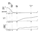
次に、図5に基づいて平坦路の場合について説明する。 Next, the case of a flat road will be described with reference to FIG.
まず、t=t1では、ブレーキの油圧が所定値以上であるので、電気自動車1は停止しており、ここでは図示しないが他の停止条件が成立していて、MCUはスリープ状態にある。なお、電気自動車1は停止状態であるので、トルクもモータ回転速度も0である。
First, at t = t1, since the brake hydraulic pressure is equal to or higher than a predetermined value, the
そして、t=t2前後から、運転者が徐々に足をブレーキから離すことによりブレーキの油圧が徐々に下降する。なお、電気自動車はまだ停止状態であるので、トルクもモータ回転速度も0である。t=t3でも同様である。 From about t = t2, the brake oil pressure gradually decreases as the driver gradually removes his / her foot from the brake. Since the electric vehicle is still in a stopped state, neither torque nor motor rotation speed is zero. The same applies to t = t3.
t=t4で、ブレーキ油圧が油圧所定値未満となったことから、ECUがMCUをスリープ状態から再始動するように信号を送出する。また、ECUからMCUへ再始動するように信号が送出されると同時に、路面傾斜判定部に判定開始を示す信号が入力される。 At t = t4, since the brake hydraulic pressure is less than the predetermined value, the ECU sends a signal to restart the MCU from the sleep state. In addition, at the same time as a signal is sent from the ECU to the MCU to restart, a signal indicating the start of determination is input to the road surface inclination determination unit.
t=t4で路面傾斜判定部に判定開始を示す信号が入力されると、モータ回転速度積算部は一定時間毎に取得されているモータのモータ回転速度を累積積算し、積算値を算出する。また、t=t4で路面傾斜判定部に判定開始を示す信号が入力されると、クリープトルク判定部がクリープトルクが発生しているかどうかの判定を開始する。 When a signal indicating determination start is input to the road surface inclination determination unit at t = t4, the motor rotation speed integration unit accumulates and integrates the motor rotation speeds of the motors acquired at regular intervals, and calculates an integration value. Further, when a signal indicating determination start is input to the road surface inclination determination unit at t = t4, the creep torque determination unit starts determining whether or not creep torque is generated.
この図5に示す場合には、t=t5でMCUが始動してトルクが発生するまで、モータ回転速度の積算値は0である。また、t=t5の場合に、モータ回転速度は0であるため、路面判定部は、平坦地と判定する。この場合には、傾斜状態判定部は、モータ回転速度の積算値は0であるため、勾配は0の平坦地であると判定する。 In the case shown in FIG. 5, the integrated value of the motor rotation speed is zero until the MCU is started and torque is generated at t = t5. Further, when t = t5, the motor rotation speed is 0, so the road surface determination unit determines that the road is flat. In this case, since the integrated value of the motor rotation speed is 0, the inclination state determination unit determines that the slope is a flat ground with 0.
そして、t=t6で運転者によりアクセルがオン状態となった場合に、ECUは路面状態が平坦路であることを認識しているので、MCUはこの路面状態に合わせて運転者の要求する運転状態を実現するためにトルクを小さく出力することができるようにモータを駆動制御する。これにより、運転者が要求する出力を得ることができ、安定して走行を行うことが可能である。 Then, when the accelerator is turned on by the driver at t = t6, the ECU recognizes that the road surface state is a flat road, so the MCU performs the driving requested by the driver in accordance with this road surface state. In order to realize the state, the motor is controlled to be able to output a small torque. As a result, the output required by the driver can be obtained and the vehicle can travel stably.
次に、図6に基づいて下り坂の場合について説明する。 Next, the downhill case will be described with reference to FIG.
まず、t=t1では、ブレーキの油圧が所定値以上であるので、電気自動車1は停止しており、ここでは図示しないが他の停止条件が成立していて、MCUはスリープ状態にある。なお、電気自動車1は停止状態であるので、トルクもモータ回転速度も0である。
First, at t = t1, since the brake hydraulic pressure is equal to or higher than a predetermined value, the
そして、t=t2前後から、運転者が徐々に足をブレーキから離すことによりブレーキの油圧が徐々に下降する。なお、電気自動車はまだ停止状態であるので、トルクもモータ回転速度も0である。 From about t = t2, the brake oil pressure gradually decreases as the driver gradually removes his / her foot from the brake. Since the electric vehicle is still in a stopped state, neither torque nor motor rotation speed is zero.
t=t3で、電気自動車はやや自重で前進を始め、モータ回転速度のみ検出される状態となる。 At t = t3, the electric vehicle starts moving forward with its own weight and only the motor rotation speed is detected.
t=t4で、ブレーキ油圧が油圧所定値未満となったことから、ECUがMCUをスリープ状態から再始動するように信号を送出する。また、ECUからMCUへ再始動するように信号が送出されると同時に、路面傾斜判定部に判定開始を示す信号が入力される。 At t = t4, since the brake hydraulic pressure is less than the predetermined value, the ECU sends a signal to restart the MCU from the sleep state. In addition, at the same time as a signal is sent from the ECU to the MCU to restart, a signal indicating the start of determination is input to the road surface inclination determination unit.
t=t4で、路面傾斜判定部は、判定開始を示す信号が入力されると、モータ回転速度積算部で一定時間毎に取得されていたモータのモータ回転速度を累積積算し、積算値を算出する。また、路面傾斜判定部に判定開始を示す信号が入力されると、クリープトルク判定部がクリープトルクが発生しているかどうかの判定を開始する。 At t = t4, when a signal indicating the start of determination is input, the road surface inclination determination unit cumulatively integrates the motor rotation speed of the motor acquired at regular intervals by the motor rotation speed integration unit, and calculates an integrated value. To do. Further, when a signal indicating the start of determination is input to the road surface inclination determination unit, the creep torque determination unit starts determining whether or not creep torque is generated.
そして、t=t5で、モータ回転速度積算部は、クリープトルクの発生を示す判定信号が入力されると、モータ回転速度の積算値の算出を停止する。即ち、積算されたモータ回転速度とは、図6中、領域Cの面積となる。そして、モータ回転速度積算部は、領域Cの面積に等しい積算値を示す信号を傾斜状態判定部に送出する。 Then, at t = t5, when the determination signal indicating the generation of creep torque is input, the motor rotation speed integration unit stops calculating the integrated value of the motor rotation speed. That is, the integrated motor rotation speed is the area of region C in FIG. Then, the motor rotation speed integration unit sends a signal indicating an integration value equal to the area of region C to the tilt state determination unit.
また、路面判定部は、クリープトルクの発生を示す判定信号が入力されると、その時のモータ回転速度が正であるので、路面は下り坂であると判定する。そして、路面判定部は、路面状態(下り坂)を示す信号を傾斜状態判定部に送出する。 Further, when a determination signal indicating the generation of creep torque is input, the road surface determination unit determines that the road surface is downhill because the motor rotation speed at that time is positive. Then, the road surface determination unit sends a signal indicating the road surface state (downhill) to the inclination state determination unit.
傾斜状態判定部は、この積算値を示す信号と、路面状態を示す信号とから、路面状態を判定する。本実施形態では、積算値を示す信号が領域Cの面積に等しい積算値を示し、路面状態を示す信号が下り坂であることを示している。傾斜状態判定部は、領域Cの面積に対応した積算値が、値q1〜q2の間(q1<C<q2)にあることから、勾配の小さい下り坂であると判定する。 The inclination state determination unit determines the road surface state from the signal indicating the integrated value and the signal indicating the road surface state. In the present embodiment, the signal indicating the integrated value indicates an integrated value equal to the area of the region C, and the signal indicating the road surface state is a downhill. Since the integrated value corresponding to the area of the region C is between the values q1 and q2 (q1 <C <q2), the inclination state determination unit determines that the slope is a downhill with a small gradient.
t=t5以降、この傾斜状態判定部の判定結果に基づいてMCUがモータのトルクの出力を設定する。本実施形態では、トルクを標準勾配の下り坂の場合よりもやや抑制する程度のトルクを出力することができるように設定されている。 After t = t5, the MCU sets the output of the motor torque based on the determination result of the inclination state determination unit. In the present embodiment, the torque is set so as to be able to be output to a degree that slightly suppresses the torque as compared with the case of a downhill with a standard gradient.
そして、t=t6で運転者によりアクセルがオン状態となった場合に、ECUは路面状態が勾配の小さい下り坂であることを認識しているので、MCUはこの路面状態に合わせて運転者の要求する運転状態を実現するためにトルクを小さく出力することができるようにモータを駆動制御する。これにより、運転者が要求する出力を得ることができ、安定して走行を行うことが可能である。 Then, when the accelerator is turned on by the driver at t = t6, the ECU recognizes that the road surface state is a downhill with a small gradient, so the MCU adjusts the driver's The motor is driven and controlled so that the torque can be output small in order to realize the requested operating state. As a result, the output required by the driver can be obtained and the vehicle can travel stably.
以上述べたように、本実施形態においては、路面傾斜判定部12を備えることで路面の傾斜状態を判定でき、これにより路面に応じてトルクを設定することができるので、安定した走行を確保することが可能である。
As described above, in the present embodiment, the road surface
本実施形態では、停止条件の解除をブレーキの油圧で判定したがこれに限定されない。他の停止条件(例えばアクセルが全閉であるか否か)で判定してもよい。 In this embodiment, the release of the stop condition is determined by the brake hydraulic pressure, but the present invention is not limited to this. You may determine by other stop conditions (for example, whether an accelerator is fully closed).
本実施形態では、モータ回転速度の積算は勾配の判定にのみ用いたが、これに限定されない。例えば、モータ回転速度の積算値のプラスマイナスを検出することにより、路面状態を検出しても良い。即ち、モータ回転速度がマイナスであって、下り坂を示している場合には、積算した値はマイナスになるので、モータの積算値の正負を判定することで、路面状態を検出するように構成してもよい。このように積算値を用いて路面状態を判定するように構成すると、モータ回転速度やモータの回転方向のみにより路面状態を判定する場合よりも、より正確に判定することができる。即ち、例えば路面に傾斜がなくても路面が荒れていて凹凸がある場合には、判定時に瞬間的にモータの回転速度の正負や回転方向の正負が生じてしまい誤作動が生じる場合があるが、モータの回転速度を積算する場合には、一定の時間分指標値を積算しているので、このような誤作動を防止することができる。 In the present embodiment, the integration of the motor rotation speed is used only for determining the gradient, but is not limited to this. For example, the road surface condition may be detected by detecting the plus or minus of the integrated value of the motor rotation speed. That is, when the motor rotation speed is negative and indicates a downhill, the integrated value becomes negative, so the road surface condition is detected by determining whether the integrated value of the motor is positive or negative. May be. If the road surface state is determined using the integrated value in this way, it can be determined more accurately than when the road surface state is determined only by the motor rotation speed and the motor rotation direction. In other words, for example, if the road surface is rough and uneven even if the road surface is not inclined, the positive and negative of the rotational speed of the motor and the positive and negative of the rotational direction may occur instantaneously at the time of determination, and a malfunction may occur. When integrating the rotational speed of the motor, since the index values are integrated for a certain period of time, such a malfunction can be prevented.
本実施形態では、勾配についても判定したがこれに限定されない。少なくとも、モータ回転速度の積算値、又はモータ回転速度の正負により上り坂であるのか、下り坂であるのか、または平坦路であるのかを判定してトルクを設定しても良い。 In the present embodiment, the gradient is also determined, but the present invention is not limited to this. The torque may be set by determining whether it is an uphill, a downhill, or a flat road based on at least the integrated value of the motor rotation speed or the sign of the motor rotation speed.
本実施形態においては、MCU10が再起動したかどうかをクリープトルクの発生により検出したがこれに限定されず、例えば、MCU10の再起動にかかる時間や、クリープトルクが発生するまでの時間がどの程度であるか予め測定し、タイマーでこの測定時間を経過した時にモータ回転速度の積算を終了し、路面判定を行うように構成してもよい。
In this embodiment, whether or not the
本実施形態においては、電気自動車1を例に説明したが、ハイブリッド車等の電動車両に本発明は適用されうる。
Although the
1 電気自動車
2 モータ
3 バッテリー
4 ECU
5 ブレーキ油圧検出部
6 アクセル検出部
7 車速検出部
8 ポジション検出部
9 トルク検出部
10 MCU
11 停止・再始動判定部
12 路面傾斜判定部
21 モータ回転速度積算部
22 クリープトルク判定部
23 路面判定部
24 傾斜状態判定部
1
5 Brake oil
11 Stop /
Claims (5)
前記モータの作動中に前記モータの停止条件が成立した場合には前記モータを自動的に停止させると共に、前記停止条件が解除された場合に前記モータを再始動させるモータコントロール部と、
前記停止条件が解除されてから所定時間までの前記モータの回転速度を積算して積算値を算出し、前記積算値に基づいて路面の傾斜状態を判定する路面傾斜判定部とを備えることを特徴とする電動車両。 In an electric vehicle that runs with a motor for driving the vehicle,
A motor control unit that automatically stops the motor when a stop condition of the motor is established during operation of the motor, and restarts the motor when the stop condition is released;
A road surface inclination determination unit that calculates an integrated value by integrating the rotation speed of the motor from when the stop condition is released to a predetermined time, and determines a slope state of the road surface based on the integrated value. Electric vehicle.
5. The electric vehicle according to claim 1, wherein when the motor is restarted, the motor control unit controls an output torque of the motor according to the determined inclination state. 6.
Priority Applications (1)
| Application Number | Priority Date | Filing Date | Title |
|---|---|---|---|
| JP2010253224A JP5601466B2 (en) | 2010-11-11 | 2010-11-11 | Electric vehicle |
Applications Claiming Priority (1)
| Application Number | Priority Date | Filing Date | Title |
|---|---|---|---|
| JP2010253224A JP5601466B2 (en) | 2010-11-11 | 2010-11-11 | Electric vehicle |
Publications (2)
| Publication Number | Publication Date |
|---|---|
| JP2012105486A true JP2012105486A (en) | 2012-05-31 |
| JP5601466B2 JP5601466B2 (en) | 2014-10-08 |
Family
ID=46395208
Family Applications (1)
| Application Number | Title | Priority Date | Filing Date |
|---|---|---|---|
| JP2010253224A Expired - Fee Related JP5601466B2 (en) | 2010-11-11 | 2010-11-11 | Electric vehicle |
Country Status (1)
| Country | Link |
|---|---|
| JP (1) | JP5601466B2 (en) |
Cited By (1)
| Publication number | Priority date | Publication date | Assignee | Title |
|---|---|---|---|---|
| US9762165B2 (en) | 2012-08-09 | 2017-09-12 | Mitsubishi Electric Corporation | Control device for electric car |
Citations (5)
| Publication number | Priority date | Publication date | Assignee | Title |
|---|---|---|---|---|
| JPH09327101A (en) * | 1996-06-06 | 1997-12-16 | Denso Corp | Electric vehicle control device |
| JP2000308209A (en) * | 1999-04-22 | 2000-11-02 | Toyota Motor Corp | Hybrid vehicle power unit |
| JP2002021627A (en) * | 2000-07-04 | 2002-01-23 | Mitsubishi Motors Corp | Slope determination device |
| JP2006311644A (en) * | 2005-04-26 | 2006-11-09 | Nissan Motor Co Ltd | Vehicle drive control device |
| JP2007185070A (en) * | 2006-01-10 | 2007-07-19 | Toyota Motor Corp | Vehicle control device |
-
2010
- 2010-11-11 JP JP2010253224A patent/JP5601466B2/en not_active Expired - Fee Related
Patent Citations (5)
| Publication number | Priority date | Publication date | Assignee | Title |
|---|---|---|---|---|
| JPH09327101A (en) * | 1996-06-06 | 1997-12-16 | Denso Corp | Electric vehicle control device |
| JP2000308209A (en) * | 1999-04-22 | 2000-11-02 | Toyota Motor Corp | Hybrid vehicle power unit |
| JP2002021627A (en) * | 2000-07-04 | 2002-01-23 | Mitsubishi Motors Corp | Slope determination device |
| JP2006311644A (en) * | 2005-04-26 | 2006-11-09 | Nissan Motor Co Ltd | Vehicle drive control device |
| JP2007185070A (en) * | 2006-01-10 | 2007-07-19 | Toyota Motor Corp | Vehicle control device |
Cited By (1)
| Publication number | Priority date | Publication date | Assignee | Title |
|---|---|---|---|---|
| US9762165B2 (en) | 2012-08-09 | 2017-09-12 | Mitsubishi Electric Corporation | Control device for electric car |
Also Published As
| Publication number | Publication date |
|---|---|
| JP5601466B2 (en) | 2014-10-08 |
Similar Documents
| Publication | Publication Date | Title |
|---|---|---|
| US7516007B2 (en) | Anti-rollback control for hybrid and conventional powertrain vehicles | |
| KR101588789B1 (en) | Method and apparatus of controlling creep torque for vehicle including driving motor | |
| KR101684500B1 (en) | Method for controlling enging of hybrid electric vehicle | |
| JP5338351B2 (en) | Control device for hybrid vehicle | |
| US9199590B2 (en) | Vehicle control device, vehicle, and vehicle control method | |
| JP5928576B2 (en) | Control device for hybrid vehicle | |
| CN102765387B (en) | Method for selecting automobilism mode | |
| KR101684507B1 (en) | Control system and method of hybrid vehicle | |
| CN103661384B (en) | For the dynamic filter stopping/starting the starting of vehicle to prepare | |
| JP5737203B2 (en) | Engine control device | |
| JP2012077647A (en) | Vehicle controller | |
| KR102872107B1 (en) | Method and apparatus for sleep maintenance motion control | |
| CN104002679A (en) | Vehicle-used controller | |
| WO2015087516A2 (en) | Vehicle control apparatus | |
| JP2016156498A (en) | Vehicle control device | |
| KR101724465B1 (en) | Method and apparatus for controlling engine start for hybrid electric vehicle | |
| JP2005133682A (en) | Constant speed travel control device for hybrid vehicle | |
| JP6436240B2 (en) | Vehicle travel control method and vehicle travel control device | |
| JP2009126303A (en) | Vehicle control unit | |
| JP2000008902A (en) | Constant-speed cruise control system for vehicles | |
| JP2005304182A (en) | Control device for hybrid vehicle | |
| JP5185052B2 (en) | Vehicle control apparatus and control method | |
| JP2018008544A (en) | Hybrid vehicle | |
| JP2017030598A (en) | Hybrid vehicle and its control method | |
| JP5428898B2 (en) | Vehicle control method and vehicle control apparatus |
Legal Events
| Date | Code | Title | Description |
|---|---|---|---|
| A621 | Written request for application examination |
Free format text: JAPANESE INTERMEDIATE CODE: A621 Effective date: 20121012 |
|
| A131 | Notification of reasons for refusal |
Free format text: JAPANESE INTERMEDIATE CODE: A131 Effective date: 20130925 |
|
| A521 | Request for written amendment filed |
Free format text: JAPANESE INTERMEDIATE CODE: A523 Effective date: 20131122 |
|
| A131 | Notification of reasons for refusal |
Free format text: JAPANESE INTERMEDIATE CODE: A131 Effective date: 20140226 |
|
| A521 | Request for written amendment filed |
Free format text: JAPANESE INTERMEDIATE CODE: A523 Effective date: 20140331 |
|
| TRDD | Decision of grant or rejection written | ||
| A01 | Written decision to grant a patent or to grant a registration (utility model) |
Free format text: JAPANESE INTERMEDIATE CODE: A01 Effective date: 20140723 |
|
| A61 | First payment of annual fees (during grant procedure) |
Free format text: JAPANESE INTERMEDIATE CODE: A61 Effective date: 20140805 |
|
| R151 | Written notification of patent or utility model registration |
Ref document number: 5601466 Country of ref document: JP Free format text: JAPANESE INTERMEDIATE CODE: R151 |
|
| S531 | Written request for registration of change of domicile |
Free format text: JAPANESE INTERMEDIATE CODE: R313531 |
|
| R350 | Written notification of registration of transfer |
Free format text: JAPANESE INTERMEDIATE CODE: R350 |
|
| LAPS | Cancellation because of no payment of annual fees |