JP2012108596A - Input device - Google Patents
Input device Download PDFInfo
- Publication number
- JP2012108596A JP2012108596A JP2010254850A JP2010254850A JP2012108596A JP 2012108596 A JP2012108596 A JP 2012108596A JP 2010254850 A JP2010254850 A JP 2010254850A JP 2010254850 A JP2010254850 A JP 2010254850A JP 2012108596 A JP2012108596 A JP 2012108596A
- Authority
- JP
- Japan
- Prior art keywords
- bezel
- switch
- base
- input device
- switch unit
- Prior art date
- Legal status (The legal status is an assumption and is not a legal conclusion. Google has not performed a legal analysis and makes no representation as to the accuracy of the status listed.)
- Pending
Links
- 238000001514 detection method Methods 0.000 claims description 23
- 230000002093 peripheral effect Effects 0.000 claims description 4
- NJPPVKZQTLUDBO-UHFFFAOYSA-N novaluron Chemical compound C1=C(Cl)C(OC(F)(F)C(OC(F)(F)F)F)=CC=C1NC(=O)NC(=O)C1=C(F)C=CC=C1F NJPPVKZQTLUDBO-UHFFFAOYSA-N 0.000 description 14
- 239000000758 substrate Substances 0.000 description 7
- 229920000122 acrylonitrile butadiene styrene Polymers 0.000 description 3
- 230000008602 contraction Effects 0.000 description 3
- 239000000463 material Substances 0.000 description 3
- 239000007769 metal material Substances 0.000 description 3
- 229920003002 synthetic resin Polymers 0.000 description 3
- 239000000057 synthetic resin Substances 0.000 description 3
- 238000013459 approach Methods 0.000 description 2
- 238000013461 design Methods 0.000 description 2
- 238000010586 diagram Methods 0.000 description 2
- JOYRKODLDBILNP-UHFFFAOYSA-N Ethyl urethane Chemical compound CCOC(N)=O JOYRKODLDBILNP-UHFFFAOYSA-N 0.000 description 1
- 238000005452 bending Methods 0.000 description 1
- 238000010276 construction Methods 0.000 description 1
- 238000007796 conventional method Methods 0.000 description 1
- 230000000694 effects Effects 0.000 description 1
- 230000005611 electricity Effects 0.000 description 1
- 238000012986 modification Methods 0.000 description 1
- 230000004048 modification Effects 0.000 description 1
- 230000000149 penetrating effect Effects 0.000 description 1
- 238000012545 processing Methods 0.000 description 1
- 229920005989 resin Polymers 0.000 description 1
- 239000011347 resin Substances 0.000 description 1
- 230000035807 sensation Effects 0.000 description 1
Images


Landscapes
- Input From Keyboards Or The Like (AREA)
- Fittings On The Vehicle Exterior For Carrying Loads, And Devices For Holding Or Mounting Articles (AREA)
Abstract
Description
本発明は、入力装置に関する。 The present invention relates to an input device.
従来の技術として、車両の運転席と助手席との間のセンターコンソールに操作部を有する車両用操作装置が知られている(特許文献1参照。)。 As a conventional technique, a vehicle operation device having an operation unit in a center console between a driver seat and a passenger seat of a vehicle is known (see Patent Document 1).
従来の車両用操作装置の操作部は、複数の操作スイッチと、複数の操作スイッチの上方に設けられた操作パネルと、操作スイッチよりも下方に設けられ、操作者の指を撮像するイメージセンサと、を有して構成されている。 The operation unit of the conventional vehicle operation device includes a plurality of operation switches, an operation panel provided above the plurality of operation switches, an image sensor provided below the operation switches, and images an operator's finger. , And is configured.
ところで、上記のような車両用操作装置の中には、例えば、操作パネルが設置された部材の表面と操作パネルの表面との段差をなくすことにより、意匠として優れたものがある。しかし、操作パネルが設置された部材の表面と操作パネルの表面との段差がない操作部は、操作者が触感により操作部のスイッチの位置を確認することが困難となる問題がある。 By the way, some of the above-described vehicle operation devices have excellent designs by eliminating a step between the surface of the member on which the operation panel is installed and the surface of the operation panel, for example. However, an operation unit having no step between the surface of the member on which the operation panel is installed and the surface of the operation panel has a problem that it is difficult for the operator to confirm the position of the switch of the operation unit by touch.
従って、本発明の目的は、スイッチの位置を容易に認識することができる入力装置を提供することにある。 Accordingly, an object of the present invention is to provide an input device that can easily recognize the position of a switch.
本発明の一態様は、基部と、基部上に設けられ、操作入力可能なスイッチ部と、開口を有し、開口内にスイッチ部が収容されるように基部上に設けられたベゼルと、基部とベゼルとの間に設けられ、ベゼルに加えられた荷重により弾性変形し、スイッチ部の外周部とベゼルの開口とに段差が生じるように基部上に設けられた弾性部材と、を備えた入力装置を提供する。 One embodiment of the present invention includes a base, a switch portion that is provided on the base and that can be operated and input, a bezel that has an opening, and is provided on the base so that the switch portion is accommodated in the opening. And an elastic member provided on the base so that a step is generated between the outer periphery of the switch part and the opening of the bezel, and is elastically deformed by a load applied to the bezel. Providing a device.
本発明によれば、スイッチの位置を容易に認識することができる。 According to the present invention, the position of the switch can be easily recognized.
(実施の形態の要約)
実施の形態に係る入力装置は、基部と、基部上に設けられ、操作入力可能なスイッチ部と、開口を有し、開口内にスイッチ部が収容されるように基部上に設けられたベゼルと、基部とベゼルとの間に設けられ、ベゼルに加えられた荷重により弾性変形し、スイッチ部の外周部とベゼルの開口とに段差が生じるように基部上に設けられた弾性部材と、を備える。
(Summary of embodiment)
An input device according to an embodiment includes a base, a switch that is provided on the base and can be operated and input, and a bezel that is provided on the base so as to have an opening and accommodate the switch in the opening. An elastic member provided between the base and the bezel, elastically deformed by a load applied to the bezel, and provided on the base so that a step is generated between the outer peripheral portion of the switch portion and the opening of the bezel. .
[実施の形態]
(入力装置2の構成)
図1(a)は、実施の形態に係る入力装置を搭載した車両内部の斜視図であり、(b)は、入力装置の上面図である。図2(a)は、実施の形態に係る入力装置の図1(b)のII−II線断面図であり、(b)は、スイッチ部周辺の拡大図である。入力装置2は、例えば、図1(a)に示すように、車両1の運転席10と助手席11との間に延びて設けられたセンターコンソール12上に配置されている。また、入力装置3は、図1(b)に示すように、手のひら、又は、腕を置くことによりスイッチ部3の操作を容易とする台座部22が設けられている。
[Embodiment]
(Configuration of input device 2)
FIG. 1A is a perspective view of the inside of a vehicle on which the input device according to the embodiment is mounted, and FIG. 1B is a top view of the input device. Fig.2 (a) is the II-II sectional view taken on the line of FIG.1 (b) of the input device based on Embodiment, (b) is an enlarged view of a switch part periphery. For example, as illustrated in FIG. 1A, the
また、運転席10に着座した乗員から見て前方に位置するインストルメントパネル13には、例えば、地図や設定メニュー等を表示するメインモニタ14と、スピードメータ等の計器類が配置されるメータパネル15と、が配置されている。このメータパネル15には、例えば、メインモニタ14より小さなサブモニタ16が配置されている。このメインモニタ14には、例えば、後述するスイッチ部3の操作可能な領域を模した画像が表示される。乗員は、この画像を見ることで、スイッチ部3に視線移動することなく、スイッチ部3のタッチ操作可能な領域のレイアウトを確認することができ、スイッチ部3を容易に操作することができる。なお、操作可能な領域を模した画像とは、例えば、車両1に搭載されたオーディオ装置の入力装置としてスイッチ部3が利用可能であるとき、再生や停止等の指示を入力可能な領域の画像と、入力パネル30の上面視した画像と、を重畳した画像である。
The instrument panel 13 positioned in front of the occupant seated in the driver's seat 10 has, for example, a
入力装置2は、主に、基部としてのベース20と、ベゼル21と、弾性部材としての板ばね23と、スイッチ部3と、を備えて概略構成されている。
The
ベース20は、例えば、センターコンソール12に沿って延びる板形状を有してセンターコンソール12に取り付けられている。ベース20は、例えば、ABS樹脂等の合成樹脂、又は金属材料を用いて形成されている。また、ベース20は、センターコンソール12に接する面とは反対側のスイッチ部3が配置される位置に、一例として、凹部200が形成されている。この凹部200には、例えば、スイッチ部3の基板32を支持する複数の支持部材33が配置されている。この支持部材33は、例えば、弾性部材を用いて形成されている。この支持部材33は、例えば、上面視にて矩形状を有する基板32の4つの隅に配置されている。なお、ベース20は、例えば、センターコンソール12の一部を用いても良い。
For example, the
ベース20のベゼル21の底面に対向する上面201には、図1(b)及び図2(a)に示すように、複数の板ばね23が配置されている。
As shown in FIGS. 1B and 2A, a plurality of
ベゼル21は、例えば、センターコンソール12に沿って延びる四角柱形状を有し、ABS樹脂等の合成樹脂を用いて形成されている。ベゼル21は、例えば、車両1の進行方向の端部210の近傍に、図2(a)の紙面の上方から下方に貫通する開口211を有する。この開口211には、スイッチ部3が収容されている。開口211には、図2(a)及び(b)に示すように、段差部212が形成されている。この段差部212は、後述するスイッチ部3の段差部に対応した形状を有し、図2(a)の紙面の上方の開口211の周の径が大きく、下方の開口211の周の径が小さくなっている。その径の違いによって、段差部212が形成されている。
The
また、ベゼル21は、荷重が加えられていないとき、図2(b)に示すように、ベース20の上面201とベゼル21の裏面213との距離がW1であり、スイッチ部3の操作面300の外周部とベゼル21の開口211の上面214とは、例えば、段差がないフラットな状態となる。この距離W1は、ベゼル21に荷重が加えられることにより生じる、スイッチ部3の操作面300とベゼル21の上面214の段差と、板ばね23の収縮時の全長と、に基づいて設定される。本実施の形態の距離W1は、一例として、5〜6mmである。なお、収縮時の全長とは、収縮する方向の長さである。
Further, the
ベゼル21の上面214には、台座部22が設けられている。この台座部22は、例えば、一方の端部が、ベゼル21の上面214から図2(a)の紙面の上方に渡って曲面が形成された板形状を有している。台座部22は、乗員の手のひらを置くパームレスト、又は、腕が置かれるアームレストであり、ABS樹脂等の合成樹脂を用いて形成され、その内部には、ウレタン等のクッション材が入れられている。
A
台座部22は、例えば、乗員が台座部22に手のひら又は腕を置くと、指によるスイッチ部3の操作が容易となるように構成されている。なお、本実施の形態では、ベゼル21と台座部22は、別々の部材としているが、これに限定されず、一体であっても良い。
The
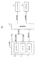
図3は、実施の形態に係る入力装置に関するブロック図である。入力装置2は、図3に示すように、車両1の車両制御部100に接続されている。この車両制御部100は、例えば、CPU(Central Processing Unit)、RAM(Random Access Memory)及びROM(Read Only Memory)等からなるマイクロコンピュータである。車両制御部100は、メインモニタ14及びサブモニタ16と接続され、これらを制御する。
FIG. 3 is a block diagram relating to the input device according to the embodiment. As shown in FIG. 3, the
入力装置2は、例えば、荷重がベゼル21に加えられることによるベース20とベゼル21との相対移動を検出する検出部4を有する。この検出部4は、例えば、ベース20とベゼル21との間に設けられ、荷重がベゼル21に加えられることによってオン状態となるスイッチである。
The
検出部4は、例えば、荷重がベゼル21に加えられていないとき、すなわち、スイッチがオフ状態となるとき、操作入力がなされたことによりスイッチ部3から出力された操作信号を無効にする検出信号を車両制御部100に出力するように構成されている。また、検出部4は、例えば、荷重がベゼル21に加えられているとき、すなわち、スイッチがオン状態となるとき、操作入力がなされたことによりスイッチ部3から出力された操作信号を有効にする検出信号を車両制御部100に出力するように構成されている。
For example, when the load is not applied to the
ここで、操作信号は、図3に示すように、入力パネル30になされた操作入力に基づいた操作入力信号と、後述するスイッチ31になされたプッシュ操作に基づいたプッシュ信号と、を含んで構成される。なお、検出部4は、ベース20とベゼル21との相対移動を検出するセンサであっても良い。また、検出部4は、ベゼル21に加えられた荷重を検出するセンサであっても良い。
Here, as shown in FIG. 3, the operation signal includes an operation input signal based on an operation input made on the
スイッチ部3は、例えば、入力パネル30と、スイッチ31と、基板32と、複数の支持部材33と、を備えて概略構成されている。スイッチ部3は、例えば、上面視にて正方形状及び長方形状等の矩形状を有し、その操作面300は、ほぼフラットである。また、スイッチ部3は、例えば、操作面300とは反対側の裏面の中央に凸部302を有し、スイッチ31のボタン310に接触している。入力パネル30の周囲には、ベゼル21の段差部212に対応した段差部301が形成されている。この段差部301は、例えば、図2(a)の紙面の上方の周の径が大きく、下方の周の径が小さくなっている。この径の違いによって、段差部301が形成されている。なお、スイッチ部3は、例えば、基板32と入力パネル30との間に弾性部材が配置され、図2(a)の紙面の上方の弾性力が入力パネル30に付加されていても良い。なお、スイッチ部3の上面視における形状は、矩形状に限定されず、円形状、多角形状等であっても良く、用途に応じて自由な形状とすることができる。
The
また、スイッチ部3は、例えば、入力パネル30に接触した指の位置に応じた操作入力信号を出力するタッチスイッチである。入力パネル30は、例えば、乗員の指の接触又は接近、すなわち、乗員のタッチ操作による静電容量の変化を信号として出力するように構成されている。また、スイッチ部3は、押下げ操作(プッシュ操作)によって、この入力パネル30が図2(b)の紙面の下方に移動することにより、スイッチ31のボタン310がオン状態となり、スイッチ31は、オン状態を示すプッシュ信号を出力するように構成されている。なお、スイッチ部3は、指の接近による、静電容量の変化量がしきい値よりも大きい場合に操作入力信号を出力するように構成されても良い。また、本実施の形態に係るスイッチ部3は、一部がタッチスイッチとして構成されるが、これに限定されず、全てがタッチスイッチ、又は、機械式スイッチであっても良い。さらに、スイッチ部3は、例えば、抵抗膜式のタッチパネルであっても良い。
The
基板32は、例えば、プリント配線基板であり、入力パネル30に対するタッチ操作、及び入力パネル30に対するプッシュ操作に基づく操作信号を車両制御部100に出力する電子回路が設けられている。
The
支持部材33は、例えば、円柱形の形状を有し、ゴム等の弾性部材、又は金属材料等を用いて形成されている。複数の支持部材33は、例えば、基板32とベース20のとの間に配置され、基板32を支持している。
The
板ばね23は、例えば、板形状の金属材料を略Z字形状に折り曲げて形成され、スイッチ部3の周囲、及び台座部22の下方に配置される。また、板ばね23は、例えば、一方の端部が接触する部材に固定され、他方の端部が接触する部材に移動可能に取り付けられる、又は、両方の端部が接触する部材に移動可能に取り付けられる。つまり、板ばね23は、例えば、両方の端部が接触する部材であるベース20とベゼル21に固定されると、図2(a)の紙面の鉛直上方から下方に向けて荷重が付加された場合、ベース20とベゼル21は、図2(a)の紙面の上下方向のみならず左右方向にも相対移動する。そこで、板ばね23は、例えば、いずれか一方の端部、又は両方の端部がベース20及びベゼル21に移動可能に取り付けられることにより、図2(a)の紙面の鉛直上方から下方に向けて荷重が付加された場合、板ばね23が横方向に移動するので、ベース20とベゼル21は、図2(a)の紙面の上下方向に相対移動することができる。
The
なお、入力装置2は、例えば、図2(a)の紙面の上方向の板ばね23の弾性力により、ベゼル21の上面214とスイッチ部3の操作面300との段差が発生しないようにベゼル21を保持するストッパを設けても良い。また、入力装置2は、例えば、走行中などのようにスイッチ部3の操作が許容されない場合に、ベース20とベゼル21の相対移動をできないようにするロック機構が設けられても良い。さらに、板ばね23は、上記の形状に限定されず、板形状の材料を用途に応じて様々な形状に加工して用いることができる。また、入力装置2に用いられる弾性部材は、弾性エネルギーを蓄積し、開放できる機械要素であれば良く、例えば、コイル状のばね、樹脂材料を用いたばね等の様々な弾性部材を用いることができる。以下に、本実施の形態に係る入力装置2の動作について説明する。
Note that the
(動作)
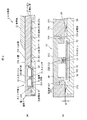
図4(a)は、実施の形態に係る荷重が加えられる前の入力装置の断面図であり、(b)は、荷重が加えられた後の入力装置の断面図である。
(Operation)
FIG. 4A is a cross-sectional view of the input device before the load according to the embodiment is applied, and FIG. 4B is a cross-sectional view of the input device after the load is applied.
まず、入力装置2の台座部22又はベゼル21に荷重が加えられていない場合、ベゼル21の上面214とスイッチ部3の操作面300とは、図4(a)に示すように、段差がないフラットな状態となる。このとき、検出部4は、オフ状態であるので、スイッチ部3になされた操作入力を無効とする検出信号を出力する。車両制御部100は、検出信号に基づいてスイッチ部3から出力された操作信号を無効とする。
First, when no load is applied to the
続いて、乗員が、スイッチ部3を操作するため、入力装置2の台座部22に手のひら又は腕を置くと、図4(b)の紙面の下向きの荷重が台座部22を介してベゼル21に加えられる。
Subsequently, when the occupant places a palm or an arm on the
ベゼル21に荷重が加えられるので、板ばね23が、ベゼル21に押し下げされることで収縮して検出部4がオン状態となり、検出部4は、スイッチ部3になされた操作入力を有効とする検出信号を出力する。車両制御部100は、有効とする検出信号に基づいてスイッチ部3から出力された操作信号を有効とする。この板ばね23の収縮により、ベゼル21の上面214とスイッチ部3の操作面300とには、図4(b)に示すように、段差が発生する。この段差W2は、一例として、2〜3mmである。
Since a load is applied to the
乗員は、例えば、指を中央部215からスイッチ部3方向に、ベゼル21の上面214に接触させながら移動させると、段差を触感として感じることができ、スイッチ部3に視線移動することなく、スイッチ部3の位置を確認することができる。さらに、乗員が入力パネル30に接触することにより、現在、スイッチ部3によって操作入力を行うことができる領域を模した画像が、メインモニタ14及びサブモニタ16の少なくともいずれか1つのモニタに表示され、乗員は、スイッチ部3に視線移動することなく、スイッチ部3によってどの様な操作が可能なのかを知ることができる。
For example, if the occupant moves the finger in the direction from the
乗員は、所望の操作を行った後、台座部22から腕を離すと、複数の板ばね23による図4(b)の紙面の上方の弾性力(復元力)により、ベゼル21の上面214とスイッチ部3の操作面300とが、段差がないフラットな状態となるように、ベース20とベゼル21とが相対移動する。この移動により、検出部4は、オフ状態となり、スイッチ部3になされた操作入力を無効とする検出信号を出力する。
When the occupant releases the arm from the
(実施の形態の効果)
本実施の形態に係る入力装置2によれば、ベゼル21とスイッチ部3とに段差が生じるので、スイッチ部3に視線移動することなく、スイッチ部3の位置を容易に認識することができる。また、入力装置2は、腕の重さ等による荷重により、段差が発生するので、電気を用いたシステムを必要とせず、省電力であり、低コストである。
(Effect of embodiment)
According to the
さらに、入力装置2は、台座部22に荷重が加わらない状態では、ベゼル21の上面214とスイッチ部3の操作面300とは、フラットな状態なので、意匠としての優秀さと、段差を発生させることによる操作の良さとを両立することができる。
Furthermore, the
またさらに、入力装置2は、段差が発生することによってスイッチ部3の操作が可能となるので、物などが当ることによる、意図しない入力を防止することができる。
Furthermore, since the
なお、上記の入力装置2は、センターコンソール12上に設けられたが、これに限定されず、乗員が着座するシートのアームレストやパームレストなどに用いられても良い。また、上記の入力装置2は、車両に搭載されたが、これに限定されず、航空機、建設機械などに搭載されても良い。
In addition, although said
また、本実施の形態の変形例として、入力装置2が検出部4を持たない構成であっても良い。検出部4を持たない場合、入力装置2のスイッチ部3からの操作信号は、常に有効である。
As a modification of the present embodiment, the
以上、本発明のいくつかの実施の形態を説明したが、これらの実施の形態は、一例に過ぎず、特許請求の範囲に係る発明を限定するものではない。これら新規な実施の形態は、その他の様々な形態で実施されることが可能であり、本発明の要旨を逸脱しない範囲で、種々の省略、置き換え、変更等を行うことができる。また、これら実施の形態の中で説明した特徴の組合せの全てが発明の課題を解決するための手段に必須であるとは限らない。さらに、これら実施の形態は、発明の範囲及び要旨に含まれるとともに、特許請求の範囲に記載された発明とその均等の範囲に含まれる。 As mentioned above, although some embodiment of this invention was described, these embodiment is only an example and does not limit the invention which concerns on a claim. These novel embodiments can be implemented in various other forms, and various omissions, replacements, changes, and the like can be made without departing from the scope of the present invention. In addition, not all the combinations of features described in these embodiments are essential to the means for solving the problems of the invention. Furthermore, these embodiments are included in the scope and gist of the invention, and are included in the invention described in the claims and the equivalents thereof.
1…車両、2…入力装置、3…スイッチ部、4…検出部、10…運転席、11…助手席、12…センターコンソール、13…インストルメントパネル、14…メインモニタ、15…メータパネル、16…サブモニタ、20…ベース、21…ベゼル、22…台座部、23…板ばね、30…入力パネル、31…スイッチ、32…基板、33…支持部材、100…車両制御部、200…凹部、201…上面、210…端部、211…開口、212…段差部、213…裏面、214…上面、215…中央部、300…操作面、301…段差部、302…凸部、310…ボタン DESCRIPTION OF SYMBOLS 1 ... Vehicle, 2 ... Input device, 3 ... Switch part, 4 ... Detection part, 10 ... Driver's seat, 11 ... Passenger seat, 12 ... Center console, 13 ... Instrument panel, 14 ... Main monitor, 15 ... Meter panel, 16 ... Sub monitor, 20 ... Base, 21 ... Bezel, 22 ... Base part, 23 ... Leaf spring, 30 ... Input panel, 31 ... Switch, 32 ... Substrate, 33 ... Support member, 100 ... Vehicle control part, 200 ... Recessed part, 201 ... Upper surface, 210 ... End, 211 ... Opening, 212 ... Stepped portion, 213 ... Back surface, 214 ... Upper surface, 215 ... Center portion, 300 ... Operation surface, 301 ... Stepped portion, 302 ... Convex portion, 310 ... Button
Claims (3)
前記基部上に設けられ、操作入力可能なスイッチ部と、
開口を有し、前記開口内に前記スイッチ部が収容されるように前記基部上に設けられたベゼルと、
前記基部と前記ベゼルとの間に設けられ、前記ベゼルに加えられた荷重により弾性変形し、前記スイッチ部の外周部と前記ベゼルの前記開口とに段差が生じるように前記基部上に設けられた弾性部材と、
を備えた入力装置。 The base,
A switch unit provided on the base and capable of operation input;
A bezel that has an opening and is provided on the base so that the switch is housed in the opening;
Provided between the base and the bezel, elastically deformed by a load applied to the bezel, and provided on the base so that a step is generated between the outer peripheral portion of the switch portion and the opening of the bezel. An elastic member;
An input device with.
前記荷重が前記ベゼルに加えられていないとき、前記検出部が、操作入力がなされたことにより前記スイッチ部から出力された操作信号を無効にする検出信号を出力する請求項1又は2に記載の入力装置。 A detector that detects relative movement between the base and the bezel caused by the load being applied to the bezel;
The detection unit according to claim 1 or 2, wherein when the load is not applied to the bezel, the detection unit outputs a detection signal that invalidates an operation signal output from the switch unit due to an operation input. Input device.
Priority Applications (1)
| Application Number | Priority Date | Filing Date | Title |
|---|---|---|---|
| JP2010254850A JP2012108596A (en) | 2010-11-15 | 2010-11-15 | Input device |
Applications Claiming Priority (1)
| Application Number | Priority Date | Filing Date | Title |
|---|---|---|---|
| JP2010254850A JP2012108596A (en) | 2010-11-15 | 2010-11-15 | Input device |
Publications (1)
| Publication Number | Publication Date |
|---|---|
| JP2012108596A true JP2012108596A (en) | 2012-06-07 |
Family
ID=46494164
Family Applications (1)
| Application Number | Title | Priority Date | Filing Date |
|---|---|---|---|
| JP2010254850A Pending JP2012108596A (en) | 2010-11-15 | 2010-11-15 | Input device |
Country Status (1)
| Country | Link |
|---|---|
| JP (1) | JP2012108596A (en) |
-
2010
- 2010-11-15 JP JP2010254850A patent/JP2012108596A/en active Pending
Similar Documents
| Publication | Publication Date | Title |
|---|---|---|
| CN113302712B (en) | Steering gear switch device and steering gear switch system | |
| JP5173044B1 (en) | Operating device | |
| JP2008532115A5 (en) | ||
| JP2016120890A (en) | Vehicular switching device | |
| KR101805104B1 (en) | Multi Switch Assembly for controlling Audio, Video and Navigation System of Vehicles | |
| JP2009298380A (en) | Input device | |
| CN106547349A (en) | Touch sensitive device with touch feedback | |
| CN110027486B (en) | Multifunctional operating device with active touch feeling and passive touch feeling | |
| US11194412B2 (en) | Operation detection device | |
| US20200218378A1 (en) | Operation detection device | |
| JP2012108596A (en) | Input device | |
| CN108306634A (en) | Control element for motor vehicle | |
| JP2014123257A (en) | Input device for vehicle | |
| JP2012109041A (en) | Input device | |
| JP5615886B2 (en) | Operating device | |
| JP6044355B2 (en) | Car electronics | |
| JP2019133273A (en) | Operation device | |
| US20220083157A1 (en) | Input device | |
| JP2014021527A (en) | Input device | |
| JP2017186121A (en) | Operation board for elevator | |
| US11385756B2 (en) | Input device | |
| JP2019152944A (en) | Operation input device | |
| JP6648735B2 (en) | Operation device | |
| JP2014081720A (en) | Input device | |
| JP2015133042A (en) | input device |