JP2012108604A - Object with rf function - Google Patents
Object with rf function Download PDFInfo
- Publication number
- JP2012108604A JP2012108604A JP2010255053A JP2010255053A JP2012108604A JP 2012108604 A JP2012108604 A JP 2012108604A JP 2010255053 A JP2010255053 A JP 2010255053A JP 2010255053 A JP2010255053 A JP 2010255053A JP 2012108604 A JP2012108604 A JP 2012108604A
- Authority
- JP
- Japan
- Prior art keywords
- article
- antenna
- function
- dish
- center
- Prior art date
- Legal status (The legal status is an assumption and is not a legal conclusion. Google has not performed a legal analysis and makes no representation as to the accuracy of the status listed.)
- Granted
Links
Images


Landscapes
- Near-Field Transmission Systems (AREA)
- Table Devices Or Equipment (AREA)
- Cash Registers Or Receiving Machines (AREA)
Abstract
【課題】多数個積み重ねても、それぞれの非接触型ICタグとの通信が可能なRF機能搭載物品を提供する。
【解決手段】本発明のRF機能搭載物品10は、平面視略円形状の皿11と、皿11に搭載され、互いに電気的に接続されたICチップ12およびアンテナ13と、を備えてなり、皿11の重心C11と、アンテナ13の重心C12とが重ならないように、糸底17の内側において、皿本体16の裏面16bにアンテナ13が配設され、皿11の外縁部において、少なくとも皿11を積み重ねた状態でそれらを側面から見た場合に視認可能な位置であって、かつ、皿11の中心を基準として等間隔にアンテナ13の配置を示す目印14,15が設けられたことを特徴とする。
【選択図】図1Provided is an RF function-equipped article that can communicate with each non-contact IC tag even when a large number of them are stacked.
An RF function-equipped article 10 of the present invention includes a dish 11 having a substantially circular shape in plan view, and an IC chip 12 and an antenna 13 mounted on the dish 11 and electrically connected to each other. the centroid C 11 dish 11, so as not to overlap with each other and the center of gravity C 12 of the antenna 13, the inside of the Itozoko 17, the antenna 13 is disposed on the rear surface 16b of the plate body 16, the outer edge of the dish 11, at least dish 11 is a position that is visible when viewed from the side in a stacked state, and that marks 14 and 15 that indicate the arrangement of the antennas 13 are provided at equal intervals with respect to the center of the dish 11. Features.
[Selection] Figure 1
Description
本発明は、積み重ね可能な物品と、その物品に搭載され、互いに電気的に接続されたICチップおよびアンテナと、を備えてなるRF機能搭載物品に関する。 The present invention relates to an RF function-equipped article comprising a stackable article, and an IC chip and an antenna mounted on the article and electrically connected to each other.
物品の識別システムとしては、個体識別情報を格納したRFタグから、電磁波または電波を媒体として、近距離(数cm〜数m)の無線通信により情報の送受信を行うRFID(Radio Frequency IDentification)システムが用いられている。このRFIDシステムは、非接触型ICタグなどのRFタグと、情報書込/読出装置(リーダライタ)との間で電磁波または電波による通信を行い、離れた位置にあるRFタグの情報を読み取ったり、RFタグに情報を書き込んだりするものである。 As an article identification system, there is an RFID (Radio Frequency IDentification) system that transmits and receives information from an RF tag storing individual identification information by radio communication at a short distance (several centimeters to several meters) using electromagnetic waves or radio waves as a medium. It is used. This RFID system performs communication by electromagnetic waves or radio waves between an RF tag such as a non-contact type IC tag and an information writing / reading device (reader / writer), and reads information on an RF tag at a remote position. Information is written on the RF tag.
このようなRFIDシステムは、配送システム、在庫管理システム、販売システム、集計システムなど、種々のシステムに応用することが検討されている。
その応用例としては、例えば、回転寿司店における皿の集計(精算)、客の趣向把握、寿司ネタの鮮度管理などを行うシステムが挙げられる。このシステムでは、寿司を載せる皿に装着した非接触型ICタグに、寿司の種類、寿司を作った時刻、寿司の売値などの情報が記録されている。
非接触型ICタグに寿司の種類を記録しておくことにより、客が寿司の載った皿を取ると、その客の趣向を把握することができる。
また、非接触型ICタグに寿司を作った時刻を記録しておくことにより、寿司の鮮度を管理して、客に対して常に作りたての寿司を提供することができるとともに、寿司を廃棄する量を低減することができる。
Application of such an RFID system to various systems such as a delivery system, an inventory management system, a sales system, and a counting system has been studied.
As an application example, for example, there is a system for collecting dishes (settlement) in a sushi restaurant, grasping customer preferences, and managing freshness of sushi. In this system, information such as the type of sushi, the time when the sushi was made, and the selling price of the sushi are recorded on a non-contact type IC tag attached to a plate on which the sushi is placed.
By recording the type of sushi on the non-contact type IC tag, the customer's taste can be grasped when the customer takes the sushi plate.
In addition, by recording the time when sushi was made on a non-contact IC tag, the freshness of the sushi can be managed to provide customers with freshly made sushi, and the amount of sushi discarded Can be reduced.
さらに、非接触型ICタグに寿司の種類および売値を記録しておくことにより、客の支払うべき金額(代金)を精算することができる。すなわち、客が食事を終えると、客が食べた寿司が載っていた皿を積み重ねて、これらの皿の非接触型ICタグと通信し、非接触型ICタグから情報(寿司の種類および売値)を取得し、代金を精算する。
このような回転寿司における集計システムに用いられる皿としては、皿の糸底の内側に非接触型ICタグを配設し、さらに、そのアンテナコイルを糸底の内壁面に設けたもの(例えば、特許文献1参照)、アンテナコイルを糸底の中央部に設けたもの(例えば、特許文献2参照)や、アンテナコイルを糸底内に埋設したもの(例えば、特許文献3参照)などが知られている。
Furthermore, by recording the type and selling price of sushi on a non-contact type IC tag, it is possible to settle the amount to be paid by the customer. In other words, when the customer finishes the meal, the dishes on which the sushi that the customer has eaten are stacked, communicated with the non-contact type IC tags of these dishes, and information (sushi type and selling price) from the non-contact type IC tags And pay the price.
As a dish used in the counting system in such a rotating sushi, a non-contact type IC tag is disposed inside the thread bottom of the dish, and the antenna coil is provided on the inner wall surface of the thread bottom (for example, patent document) 1), an antenna coil provided at the center of the yarn bottom (for example, see Patent Document 2), an antenna coil embedded in the yarn bottom (for example, see Patent Document 3), and the like.
上記の皿を用いた集計システムでは、リーダライタと、非接触型ICタグとの間で情報の送受信を行うために、例えば、固定式リーダライタ側のアンテナの上に積み重ねた皿を置いたり、積み重ねた皿の上に手持式リーダライタをかざしたりしている。
ところが、上記の皿が多数枚積み重ねられていると、それぞれの非接触型ICタグのアンテナが干渉し合って、それぞれの非接触型ICタグと通信できないという問題があった。
In the counting system using the above dishes, in order to send and receive information between the reader / writer and the non-contact type IC tag, for example, the stacked dishes are placed on the antenna on the fixed reader / writer side, A hand-held reader / writer is held over the stacked plates.
However, when a large number of the above-mentioned dishes are stacked, the antennas of the respective non-contact type IC tags interfere with each other and cannot communicate with the respective non-contact type IC tags.
本発明は、上記事情に鑑みてなされたものであって、多数個積み重ねても、それぞれの非接触型ICタグとの通信が可能なRF機能搭載物品を提供することを目的とする。 The present invention has been made in view of the above circumstances, and an object thereof is to provide an RF function-equipped article that can communicate with each non-contact type IC tag even when a large number of the tags are stacked.
本発明のRF機能搭載物品は、積み重ね可能な物品と、該物品に搭載され、互いに電気的に接続されたICチップおよびアンテナと、を備えてなり、前記物品は平面視略円形状であり、前記物品の重心と、前記アンテナの重心とが重ならないように、前記物品の一領域に前記アンテナが配設され、前記物品の外縁部において、少なくとも前記物品を積み重ねた状態でそれらを側面から見た場合に視認可能な位置であって、かつ、前記物品の中心を基準として等間隔に前記アンテナの配置を示す目印が少なくとも2つ設けられたことを特徴とする。 The RF function-equipped article of the present invention includes a stackable article, and an IC chip and an antenna that are mounted on the article and are electrically connected to each other, and the article has a substantially circular shape in plan view. The antenna is arranged in a region of the article so that the center of gravity of the article and the center of gravity of the antenna do not overlap, and at least the article is stacked on the outer edge of the article when viewed from the side. And at least two marks indicating the arrangement of the antennas at equal intervals with respect to the center of the article.
前記積み重ね可能な物品は、皿本体と、該皿本体の外底部に一体に設けられた糸底とからなる皿であり、前記アンテナが前記糸底の内側に配設されたことが好ましい。 It is preferable that the stackable article is a dish including a dish body and a thread bottom integrally provided on an outer bottom portion of the dish body, and the antenna is disposed inside the thread bottom.
本発明のRF機能搭載物品によれば、積み重ね可能な物品の重心と、アンテナの重心とが重ならないように、物品の一領域にアンテナが配設され、物品の外縁部において、少なくとも物品を積み重ねた状態でそれらを側面から見た場合に視認可能な位置であって、かつ、物品の中心を基準として等間隔にアンテナの配置を示す目印が少なくとも2つ設けられたので、RF機能搭載物品を多数積み重ねた場合、これらの重心を中心として、基準となるRF機能搭載物品に対して、他のRF機能搭載物品を回転させて、それぞれの目印が完全に重なり合わないようにすることにより、それぞれのアンテナを完全に重なり合わない位置に配することができる。その結果、それぞれのRF機能搭載物品のアンテナが干渉し合うことがなくなり、それぞれのRF機能搭載物品と、リーダライタとの間で、非接触の通信を行うことができる。すなわち、多数積み重ねられたRF機能搭載物品を、それらの側面から見て、それぞれの目印が完全に重なり合わないようにするだけで、それぞれのアンテナを完全に重なり合わない位置に配することができる。また、アンテナの配置を示す、少なくとも2つの目印が、積み重ね可能な物品の中心を基準として等間隔に設けられているので、多数積み重ねられたRF機能搭載物品を、見やすい位置から見て、目印のうち少なくとも1つが完全に重なり合わないようにすれば、それぞれのアンテナを完全に重なり合わない位置に配することができる。 According to the RF function-equipped article of the present invention, the antenna is arranged in one area of the article so that the center of gravity of the stackable article and the center of gravity of the antenna do not overlap, and at least the article is stacked at the outer edge of the article. At least two marks indicating the antenna arrangement at equal intervals with respect to the center of the article are provided so that the RF function-equipped article can be When many are stacked, by rotating the other RF function-equipped article with respect to the reference RF function-equipped article around the center of gravity, the respective marks are not completely overlapped, Antennas can be placed in positions that do not completely overlap. As a result, the antennas of the respective RF function-equipped articles do not interfere with each other, and non-contact communication can be performed between the respective RF function-equipped articles and the reader / writer. That is, it is possible to arrange the antennas at positions where the respective antennas are not completely overlapped only by preventing the marks from being completely overlapped when viewed from the side surfaces of the RF function-equipped articles stacked in large numbers. . In addition, since at least two marks indicating the arrangement of the antennas are provided at equal intervals with respect to the center of the stackable article, a large number of stacked RF function-equipped articles can be seen from an easy-to-see position. If at least one of them does not completely overlap, the respective antennas can be arranged at positions that do not completely overlap.
本発明のRF機能搭載物品の実施の形態について説明する。
なお、この実施の形態は、発明の趣旨をより良く理解させるために具体的に説明するものであり、特に指定のない限り、本発明を限定するものではない。
An embodiment of an article with an RF function according to the present invention will be described.
This embodiment is specifically described for better understanding of the gist of the invention, and does not limit the present invention unless otherwise specified.
(1)第一の実施形態
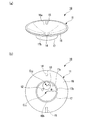
図1は、本発明のRF機能搭載物品の第一の実施形態を示す概略構成図であり、(a)は斜視図、(b)は底面図である。
この実施形態では、積み重ね可能な物品として、回転寿司店にて寿司を載せるために用いられる皿を例示する。
なお、本発明における「積み重ね可能な物品」とは、皿、皿以外のコップ(グラス)、茶碗などの食器類;CD、DVDなどの光ディスク;バケツなどの容器;各種パレットなどであって、積み重ねた状態で、その重心(中心)を中心として回転可能であり、平面視略円形状の物品である。
なお、本発明において、「略円形」とは、正五角形以上の正多角形も含む。
(1) First Embodiment FIG. 1 is a schematic configuration diagram showing a first embodiment of an RF function-equipped article of the present invention, (a) is a perspective view, and (b) is a bottom view.
In this embodiment, as a stackable article, a dish used for placing sushi at a sushi restaurant is illustrated.
The “stackable article” in the present invention refers to a plate, a tableware such as a glass other than a plate, a tea bowl, an optical disk such as a CD or a DVD, a container such as a bucket, various pallets, and the like. In this state, the article can be rotated around its center of gravity (center) and is substantially circular in plan view.
In the present invention, the “substantially circular” includes a regular polygon that is a regular pentagon or more.
このRF機能搭載物品10は、皿11と、皿11に搭載され、互いに電気的に接続されたICチップ12およびコイル状のアンテナ13と、アンテナ13の配置を示す目印14,15とから概略構成されている。
皿11は、平面視円形状でかつその表面(寿司を載せる面)16aが緩やかな上向きの曲面をなす皿本体16と、皿本体16の表面16aとは反対側の面(裏面)16bに突設され、皿本体16と一体をなす平面視円環状の糸底17とから構成されている。
This RF function-equipped
The
ICチップ12およびアンテナ13は、糸底17の内側において、皿本体16の裏面16bに配設されている。また、ICチップ12およびアンテナ13は、粘着材(図示略)または接着材(図示略)により、皿本体16の裏面16bに固着されている。
なお、コイル状のアンテナ13は、平面視円環状をなしている。
The
The
また、皿11の重心(ここでは、皿11が平面視円形状であるので、皿11の重心は、皿11の中心、すなわち、糸底17の中心と等しい。)C11と、アンテナ13の重心(ここでは、アンテナ13が平面視円環状であるので、アンテナ13の重心は、アンテナ13の中心と等しい。)C12とが重ならないように、皿本体16の裏面16bにアンテナ13が配設されている。
ここでは、糸底17の半径(糸底17の内径の半分)をR、アンテナ13の半径(アンテナ13の内径の半分)をrとした場合、半径Rと半径rが、R>2rの関係を満たし、さらに、糸底17の内側面17aの近傍に、アンテナ13の外周の一部を配置することにより、皿11の重心C11と、アンテナ13の重心C12とが重ならないようになっている。
The center of gravity of the dish 11 (here, the
Here, when the radius of the yarn bottom 17 (half of the inner diameter of the yarn bottom 17) is R and the radius of the antenna 13 (half of the inner diameter of the antenna 13) is r, the radius R and the radius r satisfy the relationship of R> 2r. further, in the vicinity of the
より詳細には、アンテナ13の重心C12は、アンテナ13が形成する面の重心であって、そのアンテナ13が形成する面の重心と、皿11の重心C11とが重ならないようになっている。
ここでは、アンテナ13が平面視円環状であるので、アンテナ13が形成する面の重心は、アンテナ13の重心C12の中心と等しい。
なお、例えば、アンテナ13が形成する面が三角形である場合、その重心は、三角形の各頂点と対辺の中点を結ぶ線分の交点のことである。例えば、アンテナ13が形成する面が四角形である場合、その重心は、四角形の各辺の中点を結んでできる平行四辺形の交点のことである。
More specifically, the center of gravity C 12 of the
Here, since the
For example, when the surface formed by the
また、皿本体16の外縁部において、RF機能搭載物品10(皿11)を積み重ねた状態で、それらを側面から見た場合に視認可能な位置であって、かつ、RF機能搭載物品10(皿11)の中心を基準として等間隔に、アンテナ13の配置を示す、2つの目印14,15が設けられている。すなわち、RF機能搭載物品10(皿11)の中心を基準として、2回の回転対称な位置、言い換えれば、RF機能搭載物品10(皿11)の中心を挟んで対向する位置に、2つの目印14,15が設けられている。
目印14は、アンテナ13の外周の一部が糸底17の内側面17aに最も近接している位置(点)を示すために、皿本体16の裏面16bであって、皿本体16の縁部およびその近傍から、皿本体16の表面16aへ延在するように設けられている。
一方、目印15は、皿11(糸底17)の中心を挟んで、目印14と対向する位置に、皿本体16の裏面16bであって、皿本体16の縁部およびその近傍から、皿本体16の表面16aへ延在するように設けられている。
Further, in the outer edge portion of the dish
The
On the other hand, the
目印14,15は、皿本体16の裏面16bおよび表面16aに施された線状または点状の印刷、皿本体16の裏面16bおよび表面16aに刻設された線状または点状の切欠などからなる。
また、2つの目印14,15の色、形状、大きさは同一であっても、異なっていてもよい。
しかしながら、RF機能搭載物品10を積み重ねた場合、目印14と目印15が完全に重なり合っても、それぞれのRF機能搭載物品10のアンテナ13が重なり合わないので、それぞれのアンテナ13が干渉し合うことがなく、それぞれのRF機能搭載物品10と、リーダライタとの間で、非接触の通信を行うことができる。これに対して、目印14同士が完全に重なり合うと、それぞれのRF機能搭載物品10のアンテナ13が完全に重なり合って、それぞれのアンテナ13が干渉し合い、それぞれのRF機能搭載物品10と、リーダライタとの間で、非接触の通信を行うことができない。したがって、目印14同士が完全に重なり合うことを防止するために、2つの目印14,15の色、形状、大きさが異なっており、目印14と目印15を明確に区別できることが好ましい。
The
Further, the colors, shapes, and sizes of the two
However, when the RF function-equipped
皿11としては、陶器、磁器、ガラス、木材、アクリル樹脂、アクリロニトリル−ブタジエン−スチレン共重合体(以下、「ABS」と略す。)樹脂、耐熱ABS樹脂、メラミン樹脂、ユリア樹脂などからなるものが用いられる。
The
ICチップ12としては、特に限定されず、アンテナ13を介して非接触状態にて情報の書き込みおよび読み出しが可能であり、非接触型ICタグや非接触型ICラベル、あるいは、非接触型ICカードなどのRFIDメディアに適用可能なものであればいかなるものでも用いられる。
The
アンテナ13は、銅線などの金属線が半径rの円環状に巻き回されてなるコイル状をなしている。
あるいは、アンテナ13は、皿本体16の裏面16bに、ポリマー型導電インクを用いて所定のパターンにスクリーン印刷、インクジェット印刷などの印刷法により形成されてなるもの、導電性箔をエッチングしてなるもの、金属メッキしてなるものであり、半径rの円環状に巻き回されてなるコイル状をなしている。
The
Alternatively, the
ポリマー型導電インクとしては、例えば、銀粉末、金粉末、白金粉末、アルミニウム粉末、パラジウム粉末、ロジウム粉末、カーボン粉末(カーボンブラック、カーボンナノチューブなど)などの導電微粒子が樹脂組成物に配合されたものが挙げられる。 Examples of polymer-type conductive inks are those in which conductive fine particles such as silver powder, gold powder, platinum powder, aluminum powder, palladium powder, rhodium powder, carbon powder (carbon black, carbon nanotube, etc.) are blended in the resin composition Is mentioned.
樹脂組成物として熱硬化型樹脂を用いれば、ポリマー型導電インクは、200℃以下、例えば、100〜150℃程度でアンテナ13をなす塗膜を形成することができる熱硬化型となる。アンテナ13をなす塗膜の電気の流れる経路は、塗膜を構成する導電微粒子が互いに接触することにより形成され、この塗膜の抵抗値は10-5Ω・cmオーダーである。
また、本発明におけるポリマー型導電インクとしては、熱硬化型の他にも、光硬化型、浸透乾燥型、溶剤揮発型といった公知のものが用いられる。
If a thermosetting resin is used as the resin composition, the polymer type conductive ink becomes a thermosetting type capable of forming a coating film forming the
Further, as the polymer type conductive ink in the present invention, known ones such as a photo-curing type, a permeation drying type, and a solvent volatilization type are used in addition to the thermosetting type.
光硬化型のポリマー型導電インクは、光硬化性樹脂を樹脂組成物に含むものであり、硬化時間が短いので、製造効率を向上させることができる。光硬化型のポリマー型導電インクとしては、例えば、熱可塑性樹脂のみ、あるいは、熱可塑性樹脂と架橋性樹脂(特に、ポリエステルとイソシアネートによる架橋系樹脂など)とのブレンド樹脂組成物に、導電微粒子が60質量%以上配合され、ポリエステル樹脂が10質量%以上配合されたもの、すなわち、溶剤揮発型あるいは架橋/熱可塑併用型(ただし、熱可塑型が50質量%以上である)のものや、熱可塑性樹脂のみ、あるいは、熱可塑性樹脂と架橋性樹脂(特に、ポリエステルとイソシアネートによる架橋系樹脂など)とのブレンド樹脂組成物に、ポリエステル樹脂が10質量%以上配合されたもの、すなわち、架橋型あるいは架橋/熱可塑併用型のものなどが好適に用いられる。 The photocurable polymer type conductive ink contains a photocurable resin in the resin composition and has a short curing time, so that the production efficiency can be improved. Examples of the photocurable polymer type conductive ink include, for example, a thermoplastic resin alone, or a conductive resin fine particle in a blend resin composition of a thermoplastic resin and a crosslinkable resin (particularly, a crosslinkable resin made of polyester and isocyanate). 60% by mass or more and a polyester resin of 10% by mass or more, that is, a solvent volatile type or a crosslinked / thermoplastic combined type (however, the thermoplastic type is 50% by mass or more), heat Polyester resin alone or a blend resin composition of a thermoplastic resin and a crosslinkable resin (especially a crosslinkable resin composed of polyester and isocyanate) is blended with 10% by mass or more of a polyester resin, that is, a crosslinked type or A cross-linking / thermoplastic combination type is preferably used.
また、アンテナ13をなす導電性箔としては、銅箔、銀箔、金箔、白金箔、アルミニウム箔などが挙げられる。
さらに、アンテナ13をなす金属メッキとしては、銅メッキ、銀メッキ、金メッキ、白金メッキなどが挙げられる。
Examples of the conductive foil forming the
Furthermore, examples of the metal plating that forms the
アンテナ13の長さ(銅線の全長)は、非接触ICカードなどの非接触ICモジュールに利用できる短波帯〈HF〉、極超短波帯〈UHF〉、マイクロ波帯などの電波帯の周波数(3MHz〜30GHz)の1/2波長に相当する長さとなっている。 The length of the antenna 13 (the total length of the copper wire) is a frequency (3 MHz) of a radio wave band such as a short wave band <HF>, an ultra-high frequency band <UHF>, a microwave band, etc. that can be used for a non-contact IC module such as a non-contact IC card. The length corresponds to a half wavelength of ˜30 GHz.
次に、図1〜3を参照して、RF機能搭載物品10の使用方法を説明するとともに、RF機能搭載物品10の作用を説明する。
このRF機能搭載物品10は、回転寿司店にて寿司を載せるための皿として用いられる。
ここで、回転寿司店のシステムの概要を説明する。
回転寿司店の店内には、無端の閉ループ状のコンベアが設けられ、このコンベアに沿って客席が設けられている。
寿司は皿に載せられ、コンベアによって客席の前へと運ばれる。
客はコンベアによって運ばれてくる皿の中から、好みの寿司が載せられている皿を取る。
そして、客は寿司を食べ終えた後、テーブルの上に皿を重ねていく。
客が食事を終えると、店員が皿の枚数を、その色別または模様別に数えて、代金を精算する。
Next, with reference to FIGS. 1-3, while using the RF
This RF function-equipped
Here, an outline of the system of the conveyor belt sushi restaurant will be described.
An endless closed-loop conveyor is provided in the rotary sushi restaurant, and a customer seat is provided along the conveyor.
Sushi is placed on a plate and conveyed to the front of the audience by a conveyor.
The customer takes the plate on which the favorite sushi is placed from the plates carried by the conveyor.
And after the customers finish eating sushi, they stack the dishes on the table.
When the customer finishes the meal, the store clerk counts the number of dishes by color or pattern and settles the price.
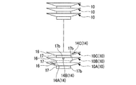
図2は、本発明のRF機能搭載物品の第一の実施形態の使用方法を示す概略正面図であり、RF機能搭載物品を多数積み重ねた状態を示す図である。
ここでは、説明を簡単にするために、下層の3つのRF機能搭載物品10A,10B,10Cの関係について説明する。
図2および3に示すように、3つのRF機能搭載物品10A,10B,10Cを積み重ねる場合、それぞれのRF機能搭載物品10の皿本体16の裏面16bであって、皿本体16の縁部およびその近傍から、皿本体16の表面16aへ延在するに設けられた目印14A,14B,14Cが完全に重なり合わないようにする。
すなわち、RF機能搭載物品10A上にRF機能搭載物品10Bを重ねた状態で、これらの重心(中心)C11を中心として、RF機能搭載物品10Aに対してRF機能搭載物品10Bを回転させることにより、これらの側面から見て、RF機能搭載物品10Aの目印14AとRF機能搭載物品10Bの目印14Bが完全に重なり合わないようにする。これにより、RF機能搭載物品10Aのアンテナ13Aと、RF機能搭載物品10Bのアンテナ13Bとが完全に重なり合わないように(図3参照)、RF機能搭載物品10A上にRF機能搭載物品10Bが載置される。
FIG. 2 is a schematic front view showing a method of using the first embodiment of the RF function-equipped article of the present invention, and is a diagram showing a state in which a large number of RF function-equipped articles are stacked.
Here, in order to simplify the description, the relationship between the lower three RF function-equipped
As shown in FIGS. 2 and 3, when three RF function-equipped
In other words, in a laminated state RF featured
さらに、RF機能搭載物品10B上にRF機能搭載物品10Cを重ねた状態で、これらの重心(中心)C11を中心として、RF機能搭載物品10AおよびRF機能搭載物品10Bに対してRF機能搭載物品10Cを回転させることにより、これらの側面から見て、目印14Aおよび目印14Bと、RF機能搭載物品10Cの目印14Cとが完全に重なり合わないようにする。これにより、アンテナ13Aおよびアンテナ13Bと、RF機能搭載物品10Cのアンテナ13Cとが完全に重なり合わないように(図3参照)、RF機能搭載物品10B上にRF機能搭載物品10Cが載置される。
Further, in a laminated state RF featured
このように目印14A,14B,14Cが完全に重なり合わないように、RF機能搭載物品10A,10B,10Cを積み重ねることにより、これらのアンテナ13A,13B,13Cが完全に重なり合わない位置に配される。
ところで、目印15は、皿11(糸底17)の中心を挟んで、目印14と対向する位置に設けられているので、目印15A,15B,15Cが完全に重なり合わないように、RF機能搭載物品10A,10B,10Cを積み重ねても、これらのアンテナ13A,13B,13Cが完全に重なり合わない位置に配される。
Thus, by stacking the RF function-equipped
By the way, the
次いで、このように積み重ねられたRF機能搭載物品10を、固定式リーダライタのアンテナ(図示略)の上に載置するか、あるいは、積み重ねられたRF機能搭載物品10の上に手持式リーダライタ(図示略)をかざす。
これにより、それぞれのRF機能搭載物品10と、リーダライタとの間で、非接触の通信を行うことができる。そして、リーダライタにより、それぞれのRF機能搭載物品10のICチップ12に記録されていた寿司の種類、寿司の売値などの情報を読み出し、その情報に基づいて、代金を精算する。
Next, the RF function-equipped
Thereby, non-contact communication can be performed between each RF
このRF機能搭載物品10によれば、皿11の重心C11と、アンテナ13の重心C12とが重ならないように、皿本体16の裏面16bにアンテナ13が配設され、アンテナ13の配置を示す、2つの目印14,15が、RF機能搭載物品10(皿11)の中心を挟んで対向する位置に設けられているので、RF機能搭載物品10を多数積み重ねた場合、これらの重心(中心)C11を中心として、基準となるRF機能搭載物品10(例えば、一番下のRF機能搭載物品10A)に対して、他のRF機能搭載物品10(10B)を回転させて、それぞれの目印14(15)が完全に重なり合わないようにすることにより、それぞれのアンテナ13が完全に重なり合わない位置に配される。その結果、それぞれのRF機能搭載物品10のアンテナ13が干渉し合うことがなくなり、それぞれのRF機能搭載物品10と、リーダライタとの間で、非接触の通信を行うことができる。すなわち、多数積み重ねられたRF機能搭載物品10を、それらの側面から見て、それぞれの目印14(15)が完全に重なり合わないようにするだけで、それぞれのアンテナ13を完全に重なり合わない位置に配することができる。
また、アンテナ13の配置を示す、2つの目印14,15が、RF機能搭載物品10(皿11)の中心を挟んで対向する位置に設けられているので、多数積み重ねられたRF機能搭載物品10を、見やすい位置から見て、目印14,15のいずれか一方が完全に重なり合わないようにすれば、それぞれのアンテナ13を完全に重なり合わない位置に配することができる。
According to the RF featured
In addition, since the two
また、糸底17の内側において、皿本体16の裏面16bにICチップ12およびアンテナ13が設けられているので、ICチップ12およびアンテナ13が皿11の使用を妨げることがない。また、ICチップ12およびアンテナ13の存在を気にすることなく、RF機能搭載物品10(皿11)を使用できる。
Further, since the
なお、この実施形態では、糸底17の内側において、皿本体16の裏面16bにICチップ12およびアンテナ13が直接設けられた場合を例示したが、本発明はこれに限定されない。本発明にあっては、糸底の内側において、皿本体の裏面に、基材と、基材の一方の面に設けられたICチップおよびアンテナを備えたインレットを設けてもよい。
インレットの基材としては、ポリエチレンテレフタレート(PET)、グリコール変性ポリエチレンテレフタレート(PET−G)、ポリブチレンテレフタレート(PBT)、ポリエチレンナフタレート(PEN)などのポリエステル樹脂からなる基材;ポリエチレン(PE)、ポリプロピレン(PP)などのポリオレフィン樹脂からなる基材;ポリフッ化ビニル、ポリフッ化ビニリデン、ポリ4フッ化エチレンなどのポリフッ化エチレン系樹脂からなる基材;ナイロン6、ナイロン6,6などのポリアミド樹脂からなる基材;ポリ塩化ビニル(PVC)、エチレン−酢酸ビニル共重合体、ポリビニルアルコール、ビニロンなどのビニル重合体からなる基材;ポリメタクリル酸メチル、ポリメタクリル酸エチル、ポリアクリル酸エチル、ポリアクリル酸ブチルなどのアクリル系樹脂からなる基材;ポリスチレンからなる基材;ポリカーボネート(PC)からなる基材;ポリアリレートからなる基材;ポリイミドからなる基材;上質紙、薄葉紙、グラシン紙、硫酸紙などの紙からなる基材などが用いられる。
In this embodiment, the case where the
As the base material of the inlet, a base material made of a polyester resin such as polyethylene terephthalate (PET), glycol-modified polyethylene terephthalate (PET-G), polybutylene terephthalate (PBT), polyethylene naphthalate (PEN); polyethylene (PE), Base material made of polyolefin resin such as polypropylene (PP); Base material made of polyfluorinated ethylene resin such as polyvinyl fluoride, polyvinylidene fluoride, polytetrafluoroethylene; From polyamide resin such as nylon 6, nylon 6,6 Substrates made of: vinyl chloride (PVC), ethylene-vinyl acetate copolymer, polyvinyl alcohol, vinylon, and other vinyl polymers; polymethyl methacrylate, polyethyl methacrylate, polyethyl acrylate, poly Base material made of acrylic resin such as butyl crylate; Base material made of polystyrene; Base material made of polycarbonate (PC); Base material made of polyarylate; Base material made of polyimide; Fine paper, thin paper, glassine paper, sulfuric acid A substrate made of paper such as paper is used.
また、この実施形態では、糸底17の内側において、皿本体16の裏面16bにICチップ12およびアンテナ13が直接設けられた場合を例示したが、本発明はこれに限定されない。本発明にあっては、糸底の内側において、皿本体の裏面に、少なくともICチップおよびアンテナを被覆するように種々の樹脂からなる被覆材が設けられていてもよい。
被覆材としては、ポリカーボネート樹脂、ポリプロピレン樹脂、ポリエチレン樹脂、ポリスチレン樹脂、アクリル樹脂、ポリエステル樹脂、ポリフェレニンサルファイド樹脂、ABS樹脂、ポリ塩化ビニル樹脂、ポリウレタン樹脂、フッ素樹脂、シリコーン樹脂などが挙げられる。
Moreover, in this embodiment, although the case where the
Examples of the coating material include polycarbonate resin, polypropylene resin, polyethylene resin, polystyrene resin, acrylic resin, polyester resin, polyferrenin sulfide resin, ABS resin, polyvinyl chloride resin, polyurethane resin, fluorine resin, and silicone resin.
また、この実施形態では、アンテナ13が半径rの円環状に巻き回されたコイル状をなす場合を例示したが、本発明はこれに限定されない。本発明にあっては、アンテナが楕円環状に巻き回されたコイル状をなしていてもよい。
Further, in this embodiment, the case where the
(2)第二の実施形態
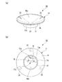
図4は、本発明のRF機能搭載物品の第二の実施形態を示す概略底面図である。
図4において、図1〜3に示したRF機能搭載物品10と同じ構成要素には同一の符号を付して説明を省略する。
このRF機能搭載物品20は、皿11と、皿11に搭載され、互いに電気的に接続されたICチップ12およびコイル状のアンテナ13と、アンテナ13の配置を示す目印21,22,23とから概略構成されている。
(2) Second Embodiment FIG. 4 is a schematic bottom view showing a second embodiment of the RF function-equipped article of the present invention.
In FIG. 4, the same components as those of the RF function-equipped
This RF function-equipped
RF機能搭載物品20では、皿本体16の外縁部において、RF機能搭載物品20(皿11)を積み重ねた状態で、それらを側面から見た場合に視認可能な位置であって、かつ、RF機能搭載物品20(皿11)の中心を基準として等間隔に、アンテナ13の配置を示す、3つの目印21,22,23が設けられている。すなわち、RF機能搭載物品20(皿11)の中心を基準として120°おきに、3つの目印21,22,23が設けられている。
目印21は、アンテナ13の外周の一部が糸底17の内側面17aに最も近接している位置(点)を示すために、皿本体16の裏面16bであって、皿本体16の縁部およびその近傍から、皿本体16の表面16aへ延在するように設けられている。
また、目印22は、RF機能搭載物品20(皿11)の中心を基準とし、皿本体16の表面16a側から見て、その外縁部に沿って時計回りに、目印21から120°離れた位置において、皿本体16の裏面16bであって、皿本体16の縁部およびその近傍から、皿本体16の表面16aへ延在するように設けられている。
さらに、目印23は、RF機能搭載物品20(皿11)の中心を基準とし、皿本体16の表面16a側から見て、その外縁部に沿って反時計回りに、目印21から120°離れた位置(外縁部に沿って時計回りに、目印21から240°離れた位置)において、皿本体16の裏面16bであって、皿本体16の縁部およびその近傍から、皿本体16の表面16aへ延在するように設けられている。
In the RF function-equipped
The
In addition, the
Further, the
目印21,22,23は、皿本体16の裏面16bおよび表面16aに施された線状または点状の印刷、皿本体16の裏面16bおよび表面16aに刻設された線状または点状の切欠などからなる。
また、3つの目印21,22,23の色、形状、大きさは同一であっても、異なっていてもよい。
しかしながら、RF機能搭載物品20を積み重ねた場合、目印21と、目印22または目印23とが完全に重なり合っても、それぞれのRF機能搭載物品20のアンテナ13が重なり合わないので、それぞれのアンテナ13が干渉し合うことがなく、それぞれのRF機能搭載物品20と、リーダライタとの間で、非接触の通信を行うことができる。これに対して、目印21同士が完全に重なり合うと、それぞれのRF機能搭載物品20のアンテナ13が完全に重なり合って、それぞれのアンテナ13が干渉し合い、それぞれのRF機能搭載物品10と、リーダライタとの間で、非接触の通信を行うことができない。したがって、目印21同士が完全に重なり合うことを防止するために、3つの目印21,22,23の色、形状、大きさが異なっており、目印21と、目印22および目印23とを明確に区別できることが好ましい。
The
Further, the colors, shapes, and sizes of the three
However, when the RF function-equipped
このRF機能搭載物品20によれば、皿11の重心C11と、アンテナ13の重心C12とが重ならないように、皿本体16の裏面16bにアンテナ13が配設され、アンテナ13の配置を示す、3つの目印21,22,23が、RF機能搭載物品20(皿11)の中心を基準として等間隔に設けられているので、RF機能搭載物品20を多数積み重ねた場合、これらの重心(中心)C11を中心として、基準となるRF機能搭載物品20に対して、他のRF機能搭載物品20を回転させて、それぞれの目印21(22,23)が完全に重なり合わないようにすることにより、それぞれのアンテナ13が完全に重なり合わない位置に配される。その結果、それぞれのRF機能搭載物品20のアンテナ13が干渉し合うことがなくなり、それぞれのRF機能搭載物品20と、リーダライタとの間で、非接触の通信を行うことができる。すなわち、多数積み重ねられたRF機能搭載物品20を、それらの側面から見て、それぞれの目印21(22,23)が完全に重なり合わないようにするだけで、それぞれのアンテナ13を完全に重なり合わない位置に配することができる。
また、アンテナ13の配置を示す、3つの目印21,22,23が、RF機能搭載物品20(皿11)の中心を基準として等間隔に設けられているので、多数積み重ねられたRF機能搭載物品20を、見やすい位置から見て、目印21,22,23のいずれか1つが完全に重なり合わないようにすれば、それぞれのアンテナ13を完全に重なり合わない位置に配することができる。
According to the RF featured
Further, since the three
なお、この実施形態では、糸底17の内側において、皿本体16の裏面16bにICチップ12およびアンテナ13が直接設けられた場合を例示したが、本発明はこれに限定されない。本発明にあっては、糸底の内側において、皿本体の裏面にICチップおよびアンテナを備えたインレットを設けてもよい。
また、この実施形態では、糸底17の内側において、皿本体16の裏面16bにICチップ12およびアンテナ13が直接設けられた場合を例示したが、本発明はこれに限定されない。本発明にあっては、糸底の内側において、皿本体の裏面に、少なくともICチップおよびアンテナを被覆するように種々の樹脂からなる被覆材が設けられていてもよい。
In this embodiment, the case where the
Moreover, in this embodiment, although the case where the
また、この実施形態では、アンテナ13が半径rの円環状に巻き回されたコイル状をなす場合を例示したが、本発明はこれに限定されない。本発明にあっては、アンテナが楕円環状に巻き回されたコイル状をなしていてもよい。
Further, in this embodiment, the case where the
(3)第三の実施形態
図5は、本発明のRF機能搭載物品の第三の実施形態を示す概略底面図である。
図5において、図1〜3に示したRF機能搭載物品10と同じ構成要素には同一の符号を付して説明を省略する。
このRF機能搭載物品30は、皿11と、皿11に搭載され、互いに電気的に接続されたICチップ12およびコイル状のアンテナ13と、アンテナ13の配置を示す目印31,32,33,34とから概略構成されている。
(3) Third Embodiment FIG. 5 is a schematic bottom view showing a third embodiment of the RF function-equipped article of the present invention.
In FIG. 5, the same components as those of the RF function-equipped
The RF function-equipped
RF機能搭載物品30では、皿本体16の外縁部において、RF機能搭載物品30(皿11)を積み重ねた状態で、それらを側面から見た場合に視認可能な位置であって、かつ、RF機能搭載物品30(皿11)の中心を基準として等間隔に、アンテナ13の配置を示す、4つの目印31,32,33,34が設けられている。すなわち、RF機能搭載物品30(皿11)の中心を基準として90°おきに、4つの目印31,32,33,34が設けられている。
目印31は、アンテナ13の外周の一部が糸底17の内側面17aに最も近接している位置(点)を示すために、皿本体16の裏面16bであって、皿本体16の縁部およびその近傍から、皿本体16の表面16aへ延在するように設けられている。
In the RF function-equipped
The
また、目印32は、RF機能搭載物品30(皿11)の中心を基準とし、皿本体16の表面16a側から見て、その外縁部に沿って時計回りに、目印31から90°離れた位置において、皿本体16の裏面16bであって、皿本体16の縁部およびその近傍から、皿本体16の表面16aへ延在するように設けられている。
また、目印33は、RF機能搭載物品30(皿11)の中心を基準とし、皿本体16の表面16a側から見て、その外縁部に沿って時計回りに、目印31から180°離れた位置において、皿本体16の裏面16bであって、皿本体16の縁部およびその近傍から、皿本体16の表面16aへ延在するように設けられている。
さらに、目印34は、RF機能搭載物品30(皿11)の中心を基準とし、皿本体16の表面16a側から見て、その外縁部に沿って時計回りに、目印31から270°離れた位置(外縁部に沿って反時計回りに、目印31から90°離れた位置)において、皿本体16の裏面16bであって、皿本体16の縁部およびその近傍から、皿本体16の表面16aへ延在するように設けられている。
The
The
Further, the
目印31,32,33,34は、皿本体16の裏面16bおよび表面16aに施された線状または点状の印刷、皿本体16の裏面16bおよび表面16aに刻設された線状または点状の切欠などからなる。
また、4つの目印31,32,33,34の色、形状、大きさは同一であっても、異なっていてもよい。
しかしながら、RF機能搭載物品30を積み重ねた場合、目印31と、目印32、目印33または目印34とが完全に重なり合っても、それぞれのRF機能搭載物品30のアンテナ13が重なり合わないので、それぞれのアンテナ13が干渉し合うことがなく、それぞれのRF機能搭載物品30と、リーダライタとの間で、非接触の通信を行うことができる。これに対して、目印31同士が完全に重なり合うと、それぞれのRF機能搭載物品30のアンテナ13が完全に重なり合って、それぞれのアンテナ13が干渉し合い、それぞれのRF機能搭載物品30と、リーダライタとの間で、非接触の通信を行うことができない。したがって、目印31同士が完全に重なり合うことを防止するために、4つの目印31,32,33,34の色、形状、大きさが異なっており、目印31と、目印32、目印33および目印34とを明確に区別できることが好ましい。
The
Further, the colors, shapes, and sizes of the four
However, when the RF function-equipped
このRF機能搭載物品30によれば、皿11の重心C11と、アンテナ13の重心C12とが重ならないように、皿本体16の裏面16bにアンテナ13が配設され、アンテナ13の配置を示す、4つの目印31,32,33,34が、RF機能搭載物品30(皿11)の中心を基準として等間隔に設けられているので、RF機能搭載物品30を多数積み重ねた場合、これらの重心(中心)C11を中心として、基準となるRF機能搭載物品30に対して、他のRF機能搭載物品30を回転させて、それぞれの目印31(32,33,34)が完全に重なり合わないようにすることにより、それぞれのアンテナ13が完全に重なり合わない位置に配される。その結果、それぞれのRF機能搭載物品30のアンテナ13が干渉し合うことがなくなり、それぞれのRF機能搭載物品30と、リーダライタとの間で、非接触の通信を行うことができる。すなわち、多数積み重ねられたRF機能搭載物品30を、それらの側面から見て、それぞれの目印31(32,33,34)が完全に重なり合わないようにするだけで、それぞれのアンテナ13を完全に重なり合わない位置に配することができる。
また、アンテナ13の配置を示す、4つの目印31,32,33,34が、RF機能搭載物品30(皿11)の中心を基準として等間隔に設けられているので、多数積み重ねられたRF機能搭載物品30を、見やすい位置から見て、目印31,32,33,34のいずれか1つが完全に重なり合わないようにすれば、それぞれのアンテナ13を完全に重なり合わない位置に配することができる。
According to the RF featured
Further, since the four
なお、この実施形態では、糸底17の内側において、皿本体16の裏面16bにICチップ12およびアンテナ13が直接設けられた場合を例示したが、本発明はこれに限定されない。本発明にあっては、糸底の内側において、皿本体の裏面にICチップおよびアンテナを備えたインレットを設けてもよい。
また、この実施形態では、糸底17の内側において、皿本体16の裏面16bにICチップ12およびアンテナ13が直接設けられた場合を例示したが、本発明はこれに限定されない。本発明にあっては、糸底の内側において、皿本体の裏面に、少なくともICチップおよびアンテナを被覆するように種々の樹脂からなる被覆材が設けられていてもよい。
In this embodiment, the case where the
Moreover, in this embodiment, although the case where the
また、この実施形態では、アンテナ13が半径rの円環状に巻き回されたコイル状をなす場合を例示したが、本発明はこれに限定されない。本発明にあっては、アンテナが楕円環状に巻き回されたコイル状をなしていてもよい。
Further, in this embodiment, the case where the
また、上述の第一〜第三の実施形態では、アンテナ13の配置を示す目印が等間隔に2〜4個設けられた場合を例示したが、本発明はこれに限定されない。本発明にあっては、積み重ね可能な物品の中心を基準として等間隔にアンテナの配置を示す目印が5つ以上設けられていてもよい。
In the first to third embodiments described above, the case where 2 to 4 marks indicating the arrangement of the
また、上述の第一〜第三の実施形態では、ICチップ12およびアンテナ13が、糸底17の内側において、皿本体16の裏面16bに配設されている場合を例示したが、本発明はこれに限定されない。本発明にあっては、ICチップおよびアンテナ、あるいは、ICチップおよびアンテナを備えたインレットが、インサート成形などにより、皿本体に埋設されていてもよい。
In the first to third embodiments described above, the case where the
また、上述の第一〜第三の実施形態では、皿11の糸底17の半径をR、アンテナ13の半径をrとした場合、半径Rと半径rが、R>2rの関係を満たす場合を例示したが、本発明はこれに限定されない。本発明にあっては、皿の糸底の半径をR、アンテナの半径をrとした場合、半径Rと半径rが、R=2rの関係を満たしていてもよく、あるいは、半径Rと半径rが、R<2rの関係を満たしていてもよい。
In the first to third embodiments described above, when the radius of the
また、上述の第一〜第三の実施形態では、積み重ね可能な物品として、回転寿司店にて寿司を載せるために用いられる皿を例示したが、本発明はこれに限定されない。本発明にあっては、積み重ね可能な物品は、コップ(グラス)、茶碗、バケツ、パレットなどであってもよい。
積み重ね可能な物品が、コップ(グラス)である場合、例えば、コップ(グラス)の底面に、上述の実施形態と同様にICチップおよびコイル状のアンテナが配設されるか、あるいは、コップ(グラス)の底部に、ICチップおよびコイル状のアンテナが埋設される。
積み重ね可能な物品が、茶碗である場合、例えば、茶碗の糸底の内側に、上述の実施形態と同様にICチップおよびコイル状のアンテナが配設されるか、あるいは、茶碗の本体に、ICチップおよびコイル状のアンテナが埋設される。
積み重ね可能な物品が、バケツである場合、例えば、バケツの底面に、上述の実施形態と同様にICチップおよびコイル状のアンテナが配設されるか、あるいは、バケツの底部に、ICチップおよびコイル状のアンテナが埋設される。
積み重ね可能な物品が、パレットである場合、例えば、パレットの底面に、上述の実施形態と同様にICチップおよびコイル状のアンテナが配設されるか、あるいは、パレットの底部に、ICチップおよびコイル状のアンテナが埋設される。
In the first to third embodiments described above, the dish used for placing sushi at a sushi restaurant is illustrated as an article that can be stacked, but the present invention is not limited to this. In the present invention, the stackable articles may be cups (glasses), teacups, buckets, pallets, and the like.
When the stackable article is a cup (glass), for example, an IC chip and a coiled antenna are disposed on the bottom surface of the cup (glass) as in the above-described embodiment, or a cup (glass) is provided. An IC chip and a coiled antenna are embedded in the bottom of).
When the stackable article is a teacup, for example, an IC chip and a coiled antenna are disposed inside the bottom of the teacup as in the above embodiment, or an IC chip is placed on the main body of the teacup. And a coiled antenna is embedded.
When the stackable article is a bucket, for example, an IC chip and a coiled antenna are disposed on the bottom surface of the bucket as in the above-described embodiment, or an IC chip and a coil are disposed on the bottom of the bucket. Shaped antenna is embedded.
When the stackable article is a pallet, for example, an IC chip and a coiled antenna are disposed on the bottom surface of the pallet as in the above-described embodiment, or an IC chip and a coil are disposed on the bottom of the pallet. Shaped antenna is embedded.
10,20,30・・・RF機能搭載物品、11・・・皿、12,72・・・ICチップ、13・・・アンテナ、14,15,21,22,23,31,32,33,34・・・目印16・・・皿本体、17・・・糸底。
10, 20, 30... RF function mounted article, 11... Dish, 12, 72... IC chip, 13 .. antenna, 14, 15, 21, 22, 23, 31, 32, 33, 34 ...
Claims (2)
前記物品は平面視略円形状であり、前記物品の重心と、前記アンテナの重心とが重ならないように、前記物品の一領域に前記アンテナが配設され、
前記物品の外縁部において、少なくとも前記物品を積み重ねた状態でそれらを側面から見た場合に視認可能な位置であって、かつ、前記物品の中心を基準として等間隔に前記アンテナの配置を示す目印が少なくとも2つ設けられたことを特徴とするRF機能搭載物品。 A stackable article, and an IC chip and an antenna mounted on the article and electrically connected to each other,
The article has a substantially circular shape in plan view, and the antenna is disposed in a region of the article so that the center of gravity of the article does not overlap the center of gravity of the antenna.
A mark indicating the arrangement of the antennas at equal intervals with respect to the center of the article, at a position that is visible at least when viewed from the side in a state where the articles are stacked in the outer edge portion of the article An RF function-equipped article, characterized in that at least two are provided.
前記アンテナが前記糸底の内側に配設されたことを特徴とする請求項1に記載のRF機能搭載物品。
The stackable article is a dish composed of a dish body and a thread bottom provided integrally with an outer bottom portion of the dish body,
The RF function-equipped article according to claim 1, wherein the antenna is disposed inside the yarn bottom.
Priority Applications (1)
| Application Number | Priority Date | Filing Date | Title |
|---|---|---|---|
| JP2010255053A JP5542630B2 (en) | 2010-11-15 | 2010-11-15 | Products with RF function |
Applications Claiming Priority (1)
| Application Number | Priority Date | Filing Date | Title |
|---|---|---|---|
| JP2010255053A JP5542630B2 (en) | 2010-11-15 | 2010-11-15 | Products with RF function |
Publications (2)
| Publication Number | Publication Date |
|---|---|
| JP2012108604A true JP2012108604A (en) | 2012-06-07 |
| JP5542630B2 JP5542630B2 (en) | 2014-07-09 |
Family
ID=46494172
Family Applications (1)
| Application Number | Title | Priority Date | Filing Date |
|---|---|---|---|
| JP2010255053A Expired - Fee Related JP5542630B2 (en) | 2010-11-15 | 2010-11-15 | Products with RF function |
Country Status (1)
| Country | Link |
|---|---|
| JP (1) | JP5542630B2 (en) |
Citations (4)
| Publication number | Priority date | Publication date | Assignee | Title |
|---|---|---|---|---|
| JPH11178695A (en) * | 1997-12-17 | 1999-07-06 | Toshiba Eng Co Ltd | Tableware with data carrier |
| JP2003178256A (en) * | 2001-12-10 | 2003-06-27 | Denso Wave Inc | Tag reader and rf tag |
| JP3141954U (en) * | 2008-03-13 | 2008-05-29 | 台灣美耐皿工業股▲ふん▼有限公司 | Container with wireless RF identification device |
| JP2009049871A (en) * | 2007-08-22 | 2009-03-05 | Sony Corp | Electronic apparatus and imaging apparatus |
-
2010
- 2010-11-15 JP JP2010255053A patent/JP5542630B2/en not_active Expired - Fee Related
Patent Citations (4)
| Publication number | Priority date | Publication date | Assignee | Title |
|---|---|---|---|---|
| JPH11178695A (en) * | 1997-12-17 | 1999-07-06 | Toshiba Eng Co Ltd | Tableware with data carrier |
| JP2003178256A (en) * | 2001-12-10 | 2003-06-27 | Denso Wave Inc | Tag reader and rf tag |
| JP2009049871A (en) * | 2007-08-22 | 2009-03-05 | Sony Corp | Electronic apparatus and imaging apparatus |
| JP3141954U (en) * | 2008-03-13 | 2008-05-29 | 台灣美耐皿工業股▲ふん▼有限公司 | Container with wireless RF identification device |
Also Published As
| Publication number | Publication date |
|---|---|
| JP5542630B2 (en) | 2014-07-09 |
Similar Documents
| Publication | Publication Date | Title |
|---|---|---|
| CN101001792B (en) | Seal with IC label and its installation method | |
| CN104428946B (en) | RF labels | |
| CN104428797B (en) | RF labels | |
| JP6186803B2 (en) | RF tag | |
| JP2002259934A (en) | Liquid container with RFID tag | |
| CN111801692A (en) | Edge attachable RFID tags | |
| JP2004018003A (en) | Cap seal with IC tag | |
| JP2010231797A (en) | Package with contactless data carrier | |
| JP2014007655A (en) | Rf tag | |
| JP6286848B2 (en) | RF tag | |
| JP5542630B2 (en) | Products with RF function | |
| JP5098587B2 (en) | Non-contact type IC tag and method of manufacturing non-contact type IC tag | |
| JP5563953B2 (en) | Products with RF function | |
| US7598876B2 (en) | Method for manufacturing a RFID electronic tag | |
| JP7251045B2 (en) | Folding RF tag label and RF tag label | |
| JP6942954B2 (en) | RF tag | |
| JP6878193B2 (en) | Paper container | |
| JP2021180447A (en) | Articles with IC chips and their manufacturing methods | |
| CN217199585U (en) | Plastic composite flexible packaging bag with radio frequency identification function | |
| JP3582439B2 (en) | Dish and reader / writer | |
| JP5599735B2 (en) | Auxiliary device and information reading method using the same | |
| JP2010225168A (en) | Package with non-contact data carrier | |
| CN102376006A (en) | Method for manufacturing radio frequency identification electronic tag | |
| JP7639435B2 (en) | RFID tags | |
| JP2005326910A (en) | Identification tag reader writer |
Legal Events
| Date | Code | Title | Description |
|---|---|---|---|
| A621 | Written request for application examination |
Free format text: JAPANESE INTERMEDIATE CODE: A621 Effective date: 20130927 |
|
| A521 | Request for written amendment filed |
Free format text: JAPANESE INTERMEDIATE CODE: A821 Effective date: 20130930 |
|
| A977 | Report on retrieval |
Free format text: JAPANESE INTERMEDIATE CODE: A971007 Effective date: 20140319 |
|
| TRDD | Decision of grant or rejection written | ||
| A01 | Written decision to grant a patent or to grant a registration (utility model) |
Free format text: JAPANESE INTERMEDIATE CODE: A01 Effective date: 20140408 |
|
| A61 | First payment of annual fees (during grant procedure) |
Free format text: JAPANESE INTERMEDIATE CODE: A61 Effective date: 20140507 |
|
| R150 | Certificate of patent or registration of utility model |
Ref document number: 5542630 Country of ref document: JP Free format text: JAPANESE INTERMEDIATE CODE: R150 |
|
| R250 | Receipt of annual fees |
Free format text: JAPANESE INTERMEDIATE CODE: R250 |
|
| R250 | Receipt of annual fees |
Free format text: JAPANESE INTERMEDIATE CODE: R250 |
|
| R250 | Receipt of annual fees |
Free format text: JAPANESE INTERMEDIATE CODE: R250 |
|
| R250 | Receipt of annual fees |
Free format text: JAPANESE INTERMEDIATE CODE: R250 |
|
| R250 | Receipt of annual fees |
Free format text: JAPANESE INTERMEDIATE CODE: R250 |
|
| R250 | Receipt of annual fees |
Free format text: JAPANESE INTERMEDIATE CODE: R250 |
|
| R250 | Receipt of annual fees |
Free format text: JAPANESE INTERMEDIATE CODE: R250 |
|
| S533 | Written request for registration of change of name |
Free format text: JAPANESE INTERMEDIATE CODE: R313533 |
|
| R350 | Written notification of registration of transfer |
Free format text: JAPANESE INTERMEDIATE CODE: R350 |
|
| S111 | Request for change of ownership or part of ownership |
Free format text: JAPANESE INTERMEDIATE CODE: R313113 |
|
| R350 | Written notification of registration of transfer |
Free format text: JAPANESE INTERMEDIATE CODE: R350 |
|
| LAPS | Cancellation because of no payment of annual fees |