JP2012108908A - Measurement object counter, and method for counting measurement object - Google Patents
Measurement object counter, and method for counting measurement object Download PDFInfo
- Publication number
- JP2012108908A JP2012108908A JP2011245559A JP2011245559A JP2012108908A JP 2012108908 A JP2012108908 A JP 2012108908A JP 2011245559 A JP2011245559 A JP 2011245559A JP 2011245559 A JP2011245559 A JP 2011245559A JP 2012108908 A JP2012108908 A JP 2012108908A
- Authority
- JP
- Japan
- Prior art keywords
- area
- counting
- moving
- measurement object
- value
- Prior art date
- Legal status (The legal status is an assumption and is not a legal conclusion. Google has not performed a legal analysis and makes no representation as to the accuracy of the status listed.)
- Granted
Links
Images





Classifications
-
- G—PHYSICS
- G06—COMPUTING OR CALCULATING; COUNTING
- G06T—IMAGE DATA PROCESSING OR GENERATION, IN GENERAL
- G06T7/00—Image analysis
- G06T7/50—Depth or shape recovery
- G06T7/55—Depth or shape recovery from multiple images
- G06T7/579—Depth or shape recovery from multiple images from motion
-
- G—PHYSICS
- G06—COMPUTING OR CALCULATING; COUNTING
- G06T—IMAGE DATA PROCESSING OR GENERATION, IN GENERAL
- G06T7/00—Image analysis
- G06T7/20—Analysis of motion
-
- G—PHYSICS
- G06—COMPUTING OR CALCULATING; COUNTING
- G06T—IMAGE DATA PROCESSING OR GENERATION, IN GENERAL
- G06T7/00—Image analysis
- G06T7/20—Analysis of motion
- G06T7/254—Analysis of motion involving subtraction of images
-
- G—PHYSICS
- G06—COMPUTING OR CALCULATING; COUNTING
- G06T—IMAGE DATA PROCESSING OR GENERATION, IN GENERAL
- G06T7/00—Image analysis
- G06T7/20—Analysis of motion
- G06T7/246—Analysis of motion using feature-based methods, e.g. the tracking of corners or segments
-
- G—PHYSICS
- G06—COMPUTING OR CALCULATING; COUNTING
- G06T—IMAGE DATA PROCESSING OR GENERATION, IN GENERAL
- G06T2207/00—Indexing scheme for image analysis or image enhancement
- G06T2207/10—Image acquisition modality
- G06T2207/10016—Video; Image sequence
-
- G—PHYSICS
- G06—COMPUTING OR CALCULATING; COUNTING
- G06T—IMAGE DATA PROCESSING OR GENERATION, IN GENERAL
- G06T2207/00—Indexing scheme for image analysis or image enhancement
- G06T2207/30—Subject of image; Context of image processing
- G06T2207/30196—Human being; Person
Landscapes
- Engineering & Computer Science (AREA)
- Computer Vision & Pattern Recognition (AREA)
- Physics & Mathematics (AREA)
- General Physics & Mathematics (AREA)
- Theoretical Computer Science (AREA)
- Multimedia (AREA)
- Image Analysis (AREA)
- Image Processing (AREA)
Abstract
【課題】本発明は、測定対象物計数器および測定対象物を計数するための方法に関する。
【解決手段】本方法は、所定の計数ビューの移動する画像を表す画像を取り込むステップと、所定の計数ビューの移動する画像内の移動領域を検出するステップと、移動領域の動きの速度を指し示す移動領域速度値を計算するステップと、所定の計数境界や、移動領域速度値や、寄与時間間隔dtに基づいて寄与ゾーンを繰り返して規定するステップと、規定した寄与ゾーン内に含有される移動領域の面積のサイズを表すサブ面積値を繰り返して取り出し、記録するステップと、複数の記録したサブ面積値を足し算することによって合計面積値を生成するステップと、合計面積値を基準測定対象物面積値で割り算することによって計数境界を通過した測定対象物の数を推定するステップとを備え、前記寄与時間間隔が、サブ面積値を取り出す2つの連続した行為間の時間間隔に対応する。
【選択図】図7The present invention relates to a measurement object counter and a method for counting a measurement object.
The method includes capturing an image representing a moving image of a predetermined counting view, detecting a moving area in the moving image of the predetermined counting view, and indicating a speed of movement of the moving area. A step of calculating a moving region speed value, a step of repeatedly defining a contribution zone based on a predetermined counting boundary, a moving region speed value, and a contribution time interval dt, and a moving region contained in the defined contribution zone A step of repeatedly extracting and recording a sub-area value representing the size of the area of the image, a step of generating a total area value by adding a plurality of recorded sub-area values, and a total area value as a reference measurement object area value Estimating the number of measurement objects that have passed the counting boundary by dividing by, wherein the contribution time interval extracts a sub-area value One of which corresponds to the time interval between successive acts.
[Selection] Figure 7
Description
本発明は、測定対象物計数器および所定の境界を通過する測定対象物を計数するための方法に関する。より詳しくは、本発明は、カメラを使用して取り込んだ画像を解析することによってかかる測定対象物を計数することに関する。 The present invention relates to a measurement object counter and a method for counting a measurement object that passes a predetermined boundary. More particularly, the present invention relates to counting such measurement objects by analyzing images captured using a camera.
境界を通過する測定対象物の数を決定するために協働するセンサおよび解析器に基づく測定対象物計数器が、種々の応用例において広く使用されている。 Measurement counters based on sensors and analyzers that work together to determine the number of measurement objects that pass the boundary are widely used in various applications.
測定対象物計数器は、例えば、デパートか、駅か、もしくはいずれかの別の関心のある区域に入るもしくは離れる人間か、ある区域を離れるもしくは入る家畜か、コンベヤベルト上を通過する製品か、またはコンベヤスライド上を通過する製品、等のような測定対象物を計数するために使用するデバイスである。測定対象物計数器を、例えば、安全目的のために使用することができるが、やはり、ある区域に入るまたは離れる測定対象物の統計データを生成するために使用することができる。 The object counter can be, for example, a department store, a station, or any other person entering or leaving the area of interest, a livestock leaving or entering an area, or a product passing on a conveyor belt, Or a device used to count a measurement object such as a product passing on a conveyor slide. A measurement object counter can be used, for example, for safety purposes, but can also be used to generate statistical data for measurement objects that enter or leave an area.
測定対象物計数器は、一般論として検知部および解析部を備える。検知部は、例えば、測定対象物の目に見えるフィーチャを検出するために光スペクトルの可視部を検出する画像センサか、例えば、測定対象物の熱プロファイルを記録するために光スペクトルの赤外部を検出するマイクロボロメータセンサのような焦点面アレイか、または画像ビュー内の測定対象物までの距離の画像を生成する飛行時間センサシステムのような、測定対象物に関係するあるフィーチャを検出するセンサに通常基づく。 The measurement object counter includes a detection unit and an analysis unit as a general theory. The detector may be, for example, an image sensor that detects the visible portion of the light spectrum to detect visible features of the measurement object, or an infrared portion of the light spectrum, for example, to record the thermal profile of the measurement object. For sensors that detect certain features related to the measurement object, such as a focal plane array such as a microbolometer sensor to detect, or a time-of-flight sensor system that generates an image of the distance to the measurement object in the image view Usually based.
検知部が、アレイ内の測定対象物のフィーチャを記録する、例えば、画像解析機器によって解釈し解析することができるデータを記録するセンサであるケースでは、解析部は、一般に画像を解析することに適合している。大部分の測定対象物計数器では、画像解析は、測定対象物検出アルゴリズムに基づき、例えば、個々の測定対象物を、センサによってカバーされる区域の至るところで検出し、識別し、追跡し、かつ測定対象物が所定の境界を通り過ぎるときに計数する。いくつかのタイプの測定対象物検出アルゴリズムが、当業者には公知である。 In the case where the detector is a sensor that records the features of the measurement object in the array, for example, data that can be interpreted and analyzed by an image analyzer, the analyzer will generally analyze the image. It fits. In most measurement object counters, image analysis is based on a measurement object detection algorithm, for example, detecting, identifying, tracking, and tracking individual measurement objects throughout the area covered by the sensor; Count when the measurement object passes a predetermined boundary. Several types of measurement object detection algorithms are known to those skilled in the art.
現在の測定対象物検出アルゴリズムの持っている1つの問題点は、密集しており、類似のフィーチャを有し、および/またはほぼ同じ速度を有する複数の測定対象物を、別々の測定対象物として検出することが非常に困難なことである。これらの問題点が明らかである状況は、例えば、測定対象物が密集してまたは違ったサイズのクラスタで互いに重なり合って配列することがあるので、コンベヤベルト上へとでたらめに送り出される測定対象物を計数するときや、人間がクラスタでしばしば入る、すなわち、密集して歩く2人以上のグループで入るので、小売店または食料雑貨店に入るまたは出る人間を計数するときや、他の類似の状況である。測定対象物のクラスタは、密集してグループを作る測定対象物のグループとして理解されたい。測定対象物のクラスタを1つの測定対象物として検出することがあるために、問題が生じる。多くの測定対象物計数器は、検出した測定対象物を単純に計数することにだけ頼っており、測定対象物がクラスタで到着する場合および各クラスタが1つの測定対象物として計数される場合には、測定対象物の数の過少評価という結果になるであろう。 One problem with current measurement object detection algorithms is that they are dense and multiple measurement objects with similar features and / or approximately the same speed as separate measurement objects. It is very difficult to detect. A situation where these problems are obvious is that, for example, the measurement objects may be densely packed or arranged on top of each other in clusters of different sizes so When counting, people often enter in clusters, ie in groups of two or more people walking in close proximity, so when counting people entering or leaving a retail or grocery store, or in other similar situations is there. A cluster of measurement objects should be understood as a group of measurement objects that form a dense group. A problem arises because a cluster of measurement objects may be detected as one measurement object. Many measurement object counters rely only on simply counting detected measurement objects, when the measurement objects arrive in clusters and when each cluster is counted as one measurement object. Will result in an underestimation of the number of objects to be measured.
ある先行技術の解決策では、検出した測定対象物中に包含される測定対象物の数のもっと正確な計数値を推定するために、検出した測定対象物の形状を解析する。しかしながら、検出した測定対象物のかかる形状解析は、大量の処理能力を必要とし、これゆえ、大量の余剰処理パワーを有するデバイスにこの方法の使用を限定している。かかる処理パワーは、小さなフォームファクタを有する組み込みシステムまたはデバイスでは利用できないことがある。 One prior art solution analyzes the shape of the detected measurement object in order to estimate a more accurate count of the number of measurement objects contained in the detected measurement object. However, such shape analysis of the detected measurement object requires a large amount of processing power and thus limits the use of this method to devices with a large amount of excess processing power. Such processing power may not be available in embedded systems or devices having a small form factor.
WO 2009/016614には、計数し測定するためのプロセスを記載している。プロセスは、計数しようとする測定対象物を何も含まない背景画像を取り込むことを含む。次に、測定対象物をカメラの前に置いたときに画像を撮影する。背景画像とは異なる面積を測定対象物として解釈し、ある係数で、または測定対象物の数を指し示す値に対して面積を結び付ける値を含んでいるルックアップテーブルを使用して、解釈した測定対象物の面積に掛け算することによって、測定対象物の数を計算することができる。この方法は、静止した測定対象物を計数するときには簡単で効果的である。しかしながら、境界を通過している移動する測定対象物を計数しようとするときには、この方法は、信頼性がない。 WO 2009/016614 describes a process for counting and measuring. The process includes capturing a background image that does not contain any measurement object to be counted. Next, an image is taken when the measurement object is placed in front of the camera. Interpret the area that is different from the background image as the measurement object, and use a lookup table that contains a value that ties the area to some value or to a value that indicates the number of measurement objects. By multiplying the area, the number of objects to be measured can be calculated. This method is simple and effective when counting stationary measurement objects. However, this method is not reliable when trying to count a moving measurement object passing through a boundary.
本発明の1つの目的は、改善した測定対象物計数器を提供することである。 One object of the present invention is to provide an improved object counter.
この目的は、請求項1に記載の方法および請求項10に記載の測定対象物計数器によって達成される。本発明のさらなる実施形態を、従属請求項に提示する。
This object is achieved by a method according to
特に、本発明の第1の態様によれば、この目的は、測定対象物を計数するための方法によって達成される。本方法は、所定の計数ビューの移動する画像を表す画像を取り込むステップと、所定の計数ビューの移動する画像内の移動領域を検出するステップと、移動領域の動きの速度を指し示す移動領域速度値を計算するステップと、所定の計数境界や、移動領域速度値や、寄与時間間隔dtに基づいて寄与ゾーンを繰り返して規定するステップと、規定した寄与ゾーン内に含有される移動領域の面積のサイズを表すサブ面積値を繰り返して取り出し、記録するステップと、複数の記録したサブ面積値を足し算することによって合計面積値を生成するステップと、合計面積値を基準測定対象物面積値で割り算することによって計数境界を通過した測定対象物の数を推定するステップとを備え、前記寄与時間間隔が、サブ面積値を取り出す2つの連続した行為間の時間間隔に対応する。 In particular, according to the first aspect of the invention, this object is achieved by a method for counting objects to be measured. The method includes the steps of capturing an image representing a moving image of a predetermined counting view, detecting a moving region in the moving image of the predetermined counting view, and a moving region speed value indicating a speed of movement of the moving region. , A step of repeatedly defining a contribution zone based on a predetermined counting boundary, a moving region speed value, and a contribution time interval dt, and the size of the area of the moving region contained in the defined contribution zone A step of repeatedly extracting and recording a sub-area value representing, a step of generating a total area value by adding a plurality of recorded sub-area values, and a division of the total area value by a reference measurement object area value Estimating the number of measurement objects that have crossed the counting boundary by the step, wherein the contribution time interval takes two successive extractions of sub-area values. Corresponding to the time interval between the act.
本方法が、限られた能力、例えば、処理能力や、記憶能力、等を有する処理環境において移動する測定対象物を計数することを容易にするという点で、本方法は有利である。この利点についての1つの理由は、本方法が面積フロー、すなわち、移動領域内のサブ面積上で動作するという事実からの結果であり、それゆえ、測定対象物追跡などの労力の必要な動作を処理することを必要としない。 The method is advantageous in that it facilitates counting objects to be measured that move in a processing environment having limited capabilities, such as processing power, storage capacity, and the like. One reason for this advantage is the result from the fact that the method operates on an area flow, i.e., a sub-area within the moving region, and therefore requires labor-intensive operations such as object tracking. Does not need to be processed.
一実施形態では、本方法は、移動する画像を取り込むことを可能にしたカメラ内で実行される。これによって、画像を人間計数器機能のためにネットワークをわたって送る必要がないために、システムの帯域幅必要量を、減少させることができる。 In one embodiment, the method is performed in a camera that allows capturing moving images. This can reduce the bandwidth requirements of the system because images do not have to be sent across the network for the human counter function.
別の一実施形態では、寄与ゾーンは、測定対象物が移動する画像内で検出される限り繰り返して規定される。 In another embodiment, the contribution zone is defined repeatedly as long as the measurement object is detected in the moving image.
さらに別の一実施形態によれば、計数境界を通過した測定対象物の計数値を推定する行為は、移動領域がそれぞれの寄与ゾーン内に存在しないときに実行される。測定対象物がそれらの対応する寄与ゾーン内に存在しないときに推定を実行することによって、それらの対応する寄与ゾーン内に存在する測定対象物に関係する処理が必要ない。これゆえ、システムは、2つの動作が同時に実行される場合よりも少ない処理能力を使用して動作することができる。 According to yet another embodiment, the act of estimating the count value of the measurement object that has passed the count boundary is performed when the moving region does not exist within the respective contribution zone. By performing the estimation when the measurement objects are not in their corresponding contribution zones, no processing related to the measurement objects present in their corresponding contribution zones is required. Thus, the system can operate using less processing power than if the two operations are performed simultaneously.
別の一実施形態によれば、本方法は、合計の計数値を表す変数に推定した計数値を足し算するステップをさらに備える。 According to another embodiment, the method further comprises the step of adding the estimated count value to a variable representing the total count value.
一実施形態では、移動領域を検出するステップが、計数ビュー内に同時に存在する複数の移動領域を検出するステップをさらに備える。複数の移動領域を検出するステップによって、異なる移動領域のサブ面積を記録するときに、各移動領域の個々の特性、例えば、速度が考慮されることがあるために、サブ面積の精度を向上させることができる。その上、速度値を計算するステップが、それぞれ検出した移動領域についての個々の速度値を計算するステップを含むことがあり、したがって、移動領域の各々についての個々の寄与ゾーンを規定することを可能にする。これによって、サブ面積の精度を、さらに向上させることさえできる。 In one embodiment, detecting the moving region further comprises detecting a plurality of moving regions that are simultaneously present in the counting view. The step of detecting a plurality of moving regions improves the accuracy of the sub-areas because the individual characteristics of each moving region, for example the speed, may be taken into account when recording the sub-areas of the different moving regions. be able to. Moreover, the step of calculating velocity values may include the step of calculating individual velocity values for each detected moving region, thus allowing to define individual contribution zones for each of the moving regions. To. Thereby, the accuracy of the sub-area can be further improved.
さらに別の一実施形態では、寄与ゾーンを規定するステップの行為が、規定した寄与ゾーン内に含有される移動領域の面積のサイズを表すサブ面積値を取り出し、記録するステップの2つの連続した行為間に実行される。 In yet another embodiment, the act of defining the contribution zone comprises two successive acts of extracting and recording a sub-area value representing the size of the area of the moving region contained within the defined contribution zone Executed in between.
別の一実施形態では、寄与ゾーンを規定する行為が、サブ面積値を取り出し、記録するステップの各行為の前に繰り返される。 In another embodiment, the act of defining the contribution zone is repeated before each act of retrieving and recording sub-area values.
本発明の別の一態様によれば、特定した計数境界を通過する測定対象物を計数するための測定対象物計数器は、所定の計数ビューの画像を取り込むために配置された画像センサと、取り込んだ画像内の移動する領域を検出し、移動領域の動きの速度を指し示す速度値を計算するために配置された移動領域検出器と、所定の計数境界や、移動領域の動きの速度や、寄与時間間隔dtに基づいて寄与ゾーンを繰り返して規定するために配置された寄与ゾーン計算器と、規定した寄与ゾーン内に含有された移動領域の面積のサイズを表すサブ面積値を取り出し、記録するために配置された面積計算器と、複数の記録したサブ面積値を足し算することによって合計面積値を積算するために配置された面積積算器と、合計面積値を基準測定対象物面積値で割り算することによって計数境界を通過した測定対象物の数を計算するために配置された測定対象物計数ユニットとを備える。 According to another aspect of the invention, a measurement object counter for counting a measurement object that passes a specified counting boundary includes an image sensor arranged to capture an image of a predetermined counting view; A moving area detector arranged to detect a moving area in the captured image and calculate a speed value indicating the moving speed of the moving area, a predetermined counting boundary, a moving speed of the moving area, A contribution zone calculator arranged to repeatedly define the contribution zone based on the contribution time interval dt, and a sub area value representing the size of the area of the moving region contained in the defined contribution zone are extracted and recorded. An area calculator arranged to add up a total area value by adding a plurality of recorded sub-area values, and the total area value as a reference measurement object area value And a measurement object counting unit arranged to calculate a measured number of objects passing through the counting boundary by dividing.
本測定対象物計数器が、限られた能力、例えば、処理能力や、記憶能力、等を有する処理環境において移動する測定対象物を計数することを容易にする点で、本測定対象物計数器は有利である。この利点についての1つの理由は、測定対象物計数器が面積フロー、すなわち、移動領域内のサブ面積上で動作するようにさせる寄与ゾーン計算器および面積計算器を、本測定対象物計数器が含むという事実からの結果であり、それゆえ、アイデンティティに決定的な意味を持つ測定対象物追跡器などの処理労力の必要な手段を必要としない。 This measurement object counter makes it easy to count measurement objects that move in a processing environment with limited capabilities, such as processing capacity, storage capacity, etc. Is advantageous. One reason for this advantage is that the measured object counter has a contribution zone calculator and an area calculator that cause the measured object counter to operate on an area flow, ie, a sub-area within the moving region. It is a result from the fact that it contains and therefore does not require any processing-necessary means such as a measurement tracker that has a critical meaning to identity.
一実施形態では、本測定対象物計数器が、カメラ内に配置される。これによって、画像を人間計数器機能のためにネットワークをわたって送る必要がないために、システムの帯域幅必要量を、減少させることができる。 In one embodiment, the measurement object counter is located in the camera. This can reduce the bandwidth requirements of the system because images do not have to be sent across the network for the human counter function.
別の一実施形態では、移動領域検出器が、計数ビュー内に同時に存在する複数の移動領域を検出するためにさらに配置される。 In another embodiment, a moving area detector is further arranged to detect multiple moving areas that are simultaneously present in the counting view.
本発明を適用可能なさらなる範囲は、下記に与えられる詳細な説明から明らかになるであろう。しかしながら、本発明の精神および範囲内での様々な変更および変形が、この詳細な説明から当業者には明らかになるので、詳細な説明および具体的な例が、本発明の好ましい実施形態を指し示しているものの、例示だけの目的で与えられることを理解されたい。 Further scope of applicability of the present invention will become apparent from the detailed description given below. However, since various changes and modifications within the spirit and scope of the invention will become apparent to those skilled in the art from this detailed description, the detailed description and specific examples refer to the preferred embodiments of the invention. However, it should be understood that this is given for illustrative purposes only.
本発明の他のフィーチャおよび利点は、添付した図面を参照して現在の好ましい実施形態の下記の詳細な説明から明らかになるであろう。 Other features and advantages of the present invention will become apparent from the following detailed description of the presently preferred embodiments, with reference to the accompanying drawings.
本発明を詳細に説明する前に、記載したデバイスおよび方法を変えることができるので、本発明が、記載したデバイスの特定の構成部品または記載した方法のステップに限定されないことを、理解すべきである。本明細書において使用する用語は、特定の実施形態だけを説明する目的のためであり、限定するようには意図していないことを、やはり理解すべきである。明細書および別記の特許請求の範囲において使用するように、冠詞「1つ(a)」や、「1つ(an)」や、「前記(the)」や、「前記(said)」は、文脈が別なように明確に指示しない限り、1つまたは複数の要素があることを意味するように意図していることに、留意しなければならない。したがって、例えば、「1つのセンサ」または「前記センサ」への言及が、いくつかのセンサを含む場合がある、等である。さらに加えて、語「備える」は、別の要素またはステップを除外しない。その上、図では、類似の参照符号は、複数の図を通して類似の部品または対応する部品を示す。 Before describing the present invention in detail, it should be understood that the invention is not limited to the specific components of the described device or the steps of the described method, as the described devices and methods can be varied. is there. It should also be understood that the terminology used herein is for the purpose of describing particular embodiments only and is not intended to be limiting. As used in the specification and the appended claims, the articles “one (a)”, “one (an)”, “the (the)”, and “said” It should be noted that unless the context clearly dictates otherwise, it is intended to mean that there is one or more elements. Thus, for example, reference to “a sensor” or “the sensor” may include several sensors, and so forth. In addition, the word “comprising” does not exclude other elements or steps. Moreover, in the figures, like reference numerals indicate like or corresponding parts throughout the several views.
本発明は、測定対象物を計数する課題に関する。測定対象物を計数するための方法は、多くのケースでは多種多様な異なる測定対象物を計数するために良く適している、すなわち、一般的方法は、特定の測定対象物のタイプによってめったにカスタマイズされない。これは、本発明にもやはりあてはまる。本発明による方法を、計数境界を横切る実質的にすべてのタイプの移動する測定対象物を計数するために、有利なことに使用することができる。計数境界は、本質的に、境界を規定する任意の形状、例えば、1つの直線や、異なる方向を有し1つの連続する境界へと接続される複数の線や、円弧や、円、等からなる場合がある。 The present invention relates to a problem of counting measurement objects. Methods for counting objects are well suited for counting a wide variety of different objects in many cases, i.e. general methods are rarely customized depending on the type of object being measured . This also applies to the present invention. The method according to the invention can advantageously be used to count virtually all types of moving measurement objects that cross a counting boundary. A counting boundary is essentially any shape that defines the boundary, such as a straight line, multiple lines having different directions and connected to a single continuous boundary, arcs, circles, etc. There is a case.
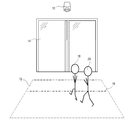
本発明の実施形態についての1つの構成を、図1に図示する。この特定の構成では、計数しようとしている人間18、20が通り過ぎる通路の画像を取り込むための計数画像ビュー12を有するカメラ10を配置する。例えば、かかる構成を、出口14および/または入口14のところに配置することができる。次に、計数境界16を通過する人間の数を計数するために、カメラ10を含むシステムを配置し、計数境界16を、計数システム内でだけ規定する境界とすることができる、すなわち、出口/入口のところで必ずしも目で見ることができる線である必要がない。通路か、出口か、または入口は、小売店や、スーパーマーケットや、デパートや、公園や、駅や、図書館や、遊園地、等にある場合がある。計数ゾーン内の、すなわち、計数画像ビュー12内の人物18がもう一人の人物20によって分かりにくくされるまたは隠されるというリスクを最小にするために、カメラ10を、計数しようとする人間の上方に配置することができ、例えば、天井にまたは壁の高いところにマウントすることができる。図1の構成を、駐車場に入るおよび/または出る自動車を計数するためのシステムにおいてやはり使用することができる。
One configuration for an embodiment of the present invention is illustrated in FIG. In this particular configuration, a
本発明の実施形態についてのもう1つの構成を、図2に図示する。この構成では、測定対象物24を搬送するコンベヤベルト22の一部をカバーする計数画像ビュー12を有するカメラ10を配置する。計数システムを、計数境界16を通過する測定対象物の数を計数するために配置する。このようにして計数した測定対象物は、人物および動物を含む任意の測定対象物である場合がある。このタイプの応用例を、生産ライン上の製品や、手荷物輸送システム内の手荷物や、エスカレータ上の人間、等を計数するために配置することができる。
Another configuration for an embodiment of the present invention is illustrated in FIG. In this configuration, a
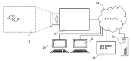
ここで図3〜図5を参照して、一実施形態の計数システムは、計数画像ビュー12の画像を記録するカメラ10およびカメラ10によって取り込まれた画像を解析し、何個の測定対象物が計数境界16を通過したかを判断するために配置された測定対象物計数器26に基づく。上記のように、計数境界16を、測定対象物計数器26内の仮想境界として規定することができる。
With reference now to FIGS. 3-5, the counting system of one embodiment analyzes the
測定対象物計数器26を、カメラの外部のデバイスとすることができ、受け取った画像に基づいて測定対象物を計数する課題のための専用のデバイスとすることができる、図3参照。しかしながら、この機能を、同様にサーバ28や、パーソナルコンピュータ30や、ワークステーション32、等の中に同様に実装することができる。測定対象物計数器26用の画像を、カメラ10からコンピュータネットワーク34を介して伝達することができる。結果を、コンピュータネットワーク34を介して同様に提示することができる。
The
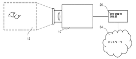
別の一実施形態によれば、測定対象物計数器26は、再び、カメラ10の外部のデバイスである、図4参照。測定対象物計数器26を、専用デバイスとすることができるが、図3に関連して示したように、測定対象物計数器26を別のデバイス内にやはり実装することができる。この実施形態では、測定対象物計数器26が、カメラ10から直接画像を受け取り、コンピュータネットワーク34を介して結果を提示するために配置されることがある。
According to another embodiment, the
さらに別の一実施形態によれば、図5参照、測定対象物計数器26を、カメラ10内に組み込むことができる。この実施形態では、計数の結果を、上記に開示したようにコンピュータネットワーク34を介して提示することができる。しかしながら、これらの実施形態のいずれかを、任意のタイプの伝送を介して結果の計数値を提示するために配置することができる。カメラ10内に測定対象物計数器26を組み込むことのいくつかの利点は、計数システムが小さな空間しか必要としないことや、計数値の基礎となる画像がネットワーク接続上を中継する代わりに内部を伝達するので、計数システムをより信頼できるものにすることができることや、1つのデバイスをインストールする必要があるだけで伝送経路を設定する必要がないので、計数システムのインストールが容易であることや、例えば、各画素が各々少なくとも3つの値によって表されるカラー画像との関連で、1つの信号値を表すデータが非常に小さいので、システムがはるかに小さな帯域幅しか必要としないこと、等である。
According to yet another embodiment, see FIG. 5, the
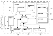
組み込まれた測定対象物計数器26を有するカメラ10を、図6に一般化したブロック図によって例示する。この実施形態は、レンズ600や、画像センサ602や、画像処理ユニット604を含み、すべてが画像を取り込むために配置される。その上、カメラは、処理ユニット606や、揮発性メモリ608や、不揮発性メモリ610や、ネットワークインターフェース612を含み、すべてが、カメラ10の一般的な動作に関連した利用および画像取り込み機能に関連した利用のために配置されている。これらの部品は、当業者には周知であり、その機能はかかる部品の通常の機能と異なる必要がない。さらに、カメラ10は、画像解析器614や、基準面積調節手段616や、測定対象物計数ユニット618を含む。画像解析器614や、基準調節手段616や、測定対象物計数ユニット618の各々を、例えば、論理回路から作られるハードウェアによって実装することができる、または処理ユニット606によって実行され、メモリ608、610中に記憶されるプログラムコードによって、これらを実装することができる。
A
画像センサ602を、例えば、測定対象物の目に見えるフィーチャを検出するために光スペクトルの可視部を検出する画像センサか、測定対象物の熱プロファイルを記録するために光スペクトルの赤外部を検出する、例えばマイクロボロメータなどの焦点面アレイか、または画像ビュー中の測定対象物までの距離の画像を生成する飛行時間センサシステムなどの、測定対象物に関係するあるフィーチャを検出する任意のセンサとすることができる。画像センサ602からの出力は、2次元画像として表すことができ、画像解析機器によって解釈し、解析することができるデータである。 Image sensor 602 detects, for example, an image sensor that detects the visible portion of the light spectrum to detect visible features of the measurement object, or an infrared portion of the light spectrum to record the thermal profile of the measurement object Any sensor that detects certain features related to the measurement object, such as a focal plane array, such as a microbolometer, or a time-of-flight sensor system that generates an image of the distance to the measurement object in the image view can do. The output from the image sensor 602 is data that can be expressed as a two-dimensional image and can be interpreted and analyzed by an image analysis device.
画像解析器は、画像センサ602によって取り込まれた画像データを解析するために配置され、移動領域の検出器620を含むことができる。移動領域の検出器620は、画像センサ602によって取り込まれた画像内の移動領域を検出するために配置され、下記に説明するように移動領域の検出に関連する機能、例えば、移動領域を検出し分割することや、検出した移動領域の速度を推定すること、等を実行する。本出願では、移動領域を、全体の領域が実質的に同じ方向に動いており、その移動領域がかかる動きを一時的に停止しているだけである画像内の画像要素、例えば、画素の領域として理解すべきである。
The image analyzer is arranged to analyze the image data captured by the image sensor 602 and can include a moving
基準面積調節手段616を、計数しようとする測定対象物についての標準サイズを指し示しているノルム値Anoを調節するために配置する。この値の調節をどのように実行するかを下記にさらに説明する。しかしながら、カメラ10がこの面積調節手段616を必ずしも含む必要がなく、むしろ標準面積値Anoを指し示す事前設定した一定値を含むことができる。Ano値を、揮発性メモリ608または不揮発性メモリ610のいずれかに記憶することができる。
The reference area adjusting means 616 is arranged to adjust the norm value A no indicating the standard size of the measurement object to be counted. How to adjust this value is further described below. However, the
測定対象物計数ユニット618を、計数画像ビュー12の計数境界16を横切った測定対象物の数に対応する値を生成するために配置する。計数境界を通過した移動領域の面積を積算し、この積算した面積を前記標準面積値Anoで割ることによって対応する値を生成するために、測定対象物計数ユニットを配置することができる。一実施形態によれば、移動領域の面積の積算を、計数境界を横切る面積フローを調査することによって実現することができる。この面積積算機能を使用可能にするために、測定対象物計数ユニット618は、計数しようとする測定対象物を潜在的に表している移動領域を含む各個別の画像についての寄与ゾーンを決定するために配置された寄与ゾーン計算器622や、寄与ゾーン内に存在する面積に対応する瞬間的な面積フローを計算するために配置された面積計算器624や、瞬間的な面積フローの積分面積を計算するために、または各サンプリング期間の間の個別の面積値を足し算しかつ計数の際に使用すべき合計面積値を積算するために配置された面積積算器626をさらに含む。測定対象物計数器の機能に関するさらなる詳細を、下記に説明する。
A measurement
別の一実施形態によれば、測定対象物計数ユニット618を、コンピュータネットワーク34を介してカメラ10に接続される別のデバイス内に配置する。さらに別の一実施形態によれば、画像解析器614や、基準調節手段616や、測定対象物計数ユニット618を、ネットワーク34を介して処理する画像情報を受け取る別のデバイス内にすべて配置することができる。
According to another embodiment, the measurement
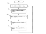
これゆえ、測定対象物を計数するための方法を、回路論理によってまたは処理ユニット606中で実行されるプログラムコードによって実装することができる。本発明の一実施形態によれば、図7参照、計数するための方法は、移動する画像を表す画像を取り込むステップ、ステップ700や、規定した計数境界を横切る移動領域の面積フローを取り込んだ画像から記録するステップ、ステップ702や、所定の時間間隔中に記録した移動領域の面積フローの積分値を計算するステップ、ステップ704を含む。積分値を計算するステップは、移動領域の面積スライスを総計するステップを含むことができる。これによって、画像ビュー内に測定対象物の存在中に個々の測定対象物を識別し追跡し続けるためのシステムを必要とせずに、測定対象物らしいものまたは計数境界を横切った測定対象物らしいものに関係する合計面積を求める。
Thus, the method for counting the measurement objects can be implemented by circuit logic or by program code executed in the
次に、結果の合計面積を基準面積で割り算し、ステップ706、割り算からの結果を、計数境界を横切った測定対象物の数を推定するために使用する、ステップ708。測定対象物の数をステップ708で推定した後で、新たな面積取り込みサイクルを開始する。
Next, the total area of the result is divided by the reference area, and step 706, the result from the division is used to estimate the number of measurement objects across the counting boundary,
所定の時間間隔を、特定の応用に対して適切である任意の長さにすることができる。別の一実施形態では、カメラによって記録されたフィーチャ、例えば、面積フローが記録されなくなるまでの積算面積により決定される時間間隔によって、所定の時間間隔を置き換えることができる。境界を横切る潜在的な測定対象物があり、次に推定を実行する限り、移動領域面積スライスを積分するステップによって、これを実装することができる。さらに別の一実施形態では、面積を、リセットせずに継続して積算し、次にユーザまたは別のシステムからの要求で、通り過ぎた測定対象物の数を提示する。 The predetermined time interval can be any length that is appropriate for the particular application. In another embodiment, the predetermined time interval can be replaced by a feature recorded by the camera, eg, a time interval determined by the accumulated area until no area flow is recorded. This can be implemented by integrating the moving area area slice as long as there is a potential measurement across the boundary and the next estimation is performed. In yet another embodiment, the area is continuously accumulated without resetting, and then the number of measurement objects passed is presented at the request from the user or another system.
特定の一実施形態によれば、正確に計数した測定対象物の面積に対応しない基準面積に関係する誤差の積算を避けるために、結果の合計面積を基準面積で割り算するステップ、ステップ706、および測定対象物の数の推定、ステップ708を、可能な限り早く実行すべきである。サイズが変わる測定対象物、例えば、人間や、動物、等を計数するときに、これは特に歴然としている。したがって、基準面積の1.2倍の合計面積が記録される場合には、1つの測定対象物が通過し、この特定の測定対象物が基準測定対象物の面積よりも幾分大きいことが予想される。しかしながら、基準面積の4.8倍の合計面積が記録される場合には、システムは、通過した測定対象物の数を5つに推定することができる。各々が基準面積の1.2倍の面積を有する4つの測定対象物が通過する場合以外では、この推定値はおそらく正しく、計数器は、5人の人物が通過したと依然として指し示すであろう。これゆえ、測定対象物の数を可能な限り早く推定する場合には、この積算された誤差を避けることができる、または低レベルに少なくとも維持することができる。
According to one particular embodiment, dividing the total area of the result by the reference area in order to avoid accumulation of errors related to the reference area not corresponding to the accurately counted area of the measurement object,
プロセスが自動的に面積を出力し測定対象物の数を推定する状態にプロセスが到達していない場合でさえ、要求に応じて、プロセスは、現在の積算した合計面積を指し示す面積値の出力をやはり認めることができる、すなわち、面積値の出力を、いかなる時点においても要求することができる。 On demand, the process still accepts an output of an area value that points to the current total accumulated area, even if the process has not yet reached a state where it automatically outputs an area and estimates the number of objects to be measured. That is, the output of the area value can be requested at any time.
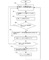
特定の一実施形態では、上記の方法を、図8のプロセスに関連して下記に説明するように実装することができる。図8に関係する下記の説明は、やはり図10〜図12を参照する。初めに、プロセスを、計数画像ビューから画像を取り込み、これらの画像ビュー内の移動領域の存在を検出するように準備する、ステップ802。
In one particular embodiment, the above method may be implemented as described below in connection with the process of FIG. The following description relating to FIG. 8 also refers to FIGS. Initially, the process prepares to capture images from the counting image views and detect the presence of moving regions in these image views,
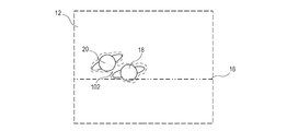
カメラ10によって取り込まれた計数画像ビューを表す図10では、2人の人物18、20を計数画像ビュー12中に取り込み移動領域を検出するステップ802が、破線によって指し示される1つの移動領域102の検出という結果をもたらす。この例では、計数画像ビュー12中に2人の人物18、20がいるという事実にも拘わらず、移動領域の検出、ステップ802が、1つの検出した移動領域102という結果をもたらした。これに関する理由は、前に述べたように、移動領域検出アルゴリズムが、互いに近接している測定対象物を見分けることが不可能であり、それゆえ、両方の人物18、20をカバーする1つの移動領域102として、移動領域102を検出することである。
In FIG. 10, which represents a counting image view captured by the
次に、検出した移動領域102の動きを記述する1つまたは複数の速度ベクトル

104を生成する、ステップ804。図10および図11中の移動領域102が1つの移動領域として検出されるので、1つだけの速度ベクトル
104が、図11に図示されている。前記生成した1つまたは複数の速度ベクトル
104は、各検出した移動領域102に関係する動きの方向および速度を含む。
Next, one or more velocity vectors describing the motion of the detected moving
104 is generated,
104 is illustrated in FIG. The generated one or more velocity vectors
104 includes the direction and speed of motion associated with each detected moving
次に、対応する移動領域102の速度および積算した合計面積に足し算すべきサブ面積値を生成する2つの連続したステップ間の時間間隔に基づいて寄与ゾーンの境界を、各検出した移動領域102について計算する、ステップ806。
Next, the boundary of the contribution zone is determined for each detected moving
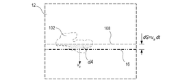
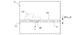
図12に例示した一実施形態によれば、寄与ゾーンを、この特定の実施形態では直線である計数境界16や、全体の計数画像ビュー12の幅や、計数境界線16に平行な直線でありかつ計数境界線16から距離dSのところに配置された寄与線108によって規定する。距離dSは、積算した合計面積に足し算すべきサブ面積値を生成する連続したステップ間の時間に対応する時間間隔dtの間に、移動領域102が計数境界線16に向かって進む距離に対応する。距離dSを、例えば、dS=vadtとして計算することができる。
According to one embodiment illustrated in FIG. 12, the contribution zone is a counting
したがって、速度vaを短い時間値dt、例えば、2つの連続したサブ面積決定間の時間や、2つの連続した画像取り込み間の時間、等で掛け算することによって、距離dSを得ることができる。この式では、変数vaは、計数境界線16に垂直な方向を有する速度ベクトル
104の速度成分である、図11参照。時間変数dtを、積算した合計面積に足し算すべきサブ面積値を生成する2つの連続したステップ間の時間または類似のサイクル、例えば、連続した寄与ゾーン計算間の時間や、移動領域が計数境界の近くにあるかどうかの連続した検査間の時間や、連続した移動領域検出間の時間、等とすることができる。しかしながら、時間変数dtを、複数のサイクル間の時間に、またはプロセスのいずれかの特定のフィーチャに関係しない一定値にやはり設定することができる。したがって、距離dSを、速度vaを短い時間値dtで掛け算することによって得ることができる。
Therefore, the distance dS can be obtained by multiplying the speed va by a short time value dt, for example, the time between two successive sub-area determinations, the time between two successive image captures, etc. In this equation, the variable v a is the velocity vector having a direction perpendicular to the counting
See FIG. 11, which is the velocity component of 104. The time variable dt is added to the integrated total area to generate a sub-area value, or the time between two consecutive steps or similar cycles, such as the time between successive contribution zone calculations, It can be the time between successive inspections whether or not they are close, the time between successive moving region detections, and the like. However, the time variable dt can still be set to a constant value that is not related to the time between multiple cycles or to any particular feature of the process. Thus, the distance dS can be obtained by multiplying the speed va by a short time value dt.
次に、検出したいずれかの移動領域102が計数境界線16の近くにあると見出される場合には、この特定の実施形態では、これは、移動領域自体に関係する寄与ゾーン内に存在することが見出されることを意味し、ステップ808、次に、各移動領域自体に関係する寄与ゾーン内に存在する各移動領域102についてサブ面積dAを生成することによって、プロセスが続く、ステップ810。
Next, if any detected moving
これゆえ、サブ面積dAを、dA=|寄与ゾーン∩移動領域|と記述することができる。寄与ゾーンおよび移動領域102の交点を、多角形クリッピングまたは寄与ゾーンと検出した移動領域102との間の画素レベルのAND演算によって決定することができる。次に、サブ面積dAを、結果の多角形の面積または結果の画素の総計として計算することができる。当業者は、サブ面積dAを決定するためのさらなる方法に気付くであろう。したがって、各サブ面積dAは、対応する寄与ゾーン内の存在する移動領域102の面積を指し示す。サブ面積dAを、面積フロー値としてやはり理解することができる。
Therefore, the sub-area dA can be described as dA = | contribution zone∩movement region |. The intersection of the contribution zone and moving
各サブ面積dAが決定されると、測定対象物検出境界16を通過する測定対象物に対応する面積を積算するために、各サブ面積dAを合計面積Atotに足し算する、ステップ812。移動領域を決定するステップ802や、速度ベクトルを生成するステップ804や、寄与ゾーンの境界16を計算するステップ806や、移動領域102が計数境界に近いかどうかを検査するステップ808や、サブ面積dAを生成するステップ810や、寄与面積dAを合計面積Atotに足し算するステップのこれらのステップを、タイマtiが時間切れになるまで繰り返す、ステップ814。タイマtiが時間切れになった後で、基準測定対象物の面積を表す値Anoによって積算した合計面積Atotを割り算することによって、時間間隔ti中に通過した測定対象物の数を決定する、ステップ816。これによって、測定対象物の数をNobj=Atot/Anoとして近似することができる。この推定した測定対象物の数を、より長い時間間隔を表す値を与えるために積算することができる、または関心のある関係者による将来のアクセスのために記憶することができる。いずれにせよ、計数境界を通過した測定対象物の数を推定すると、合計面積Atotを表す変数をリセットし、ステップ818、例えば、ゼロに設定し、プロセスは測定対象物を検出するステップ、802、に戻り、さらなる測定対象物を計数することができる。
Once each sub-area dA is determined, each sub-area dA is added to the total area A tot to add up the area corresponding to the measurement object passing through the measurement
破線を使用して描かれた追加の処理ステップ、ステップ820および822によって図9中に表されている別の一実施形態によれば、ユーザからのまたは情報交換しているシステムからの結果要求、ステップ820、を検出するように、プロセスを動作可能にすることができる。要求に応じて、プロセスが進み、基準測定対象物の面積を表す値Anoで積算した合計面積Atotを割る計算を実行する、ステップ822。プロセスは、ステップ802に戻ることによってサブ面積を積算することを続ける。この特定の実施形態では、積算した合計面積Atotをめったにリセットしないように、ti時間間隔を大きな値に設定することができる。カメラを再始動させるまたはリセットするまで、積算した合計面積Atotを決してリセットしないように、システムを設定する場合さえある。
According to another embodiment, represented in FIG. 9 by additional processing steps drawn using dashed lines, steps 820 and 822, a result request from the user or from the system exchanging information, The process can be enabled to detect
一実施形態では、領域の検出、ステップ802、および速度ベクトル
の生成、ステップ804を、カメラ10の既存の機能によって実行し、測定対象物計数プロセスへ入力する。測定対象物計数プロセスへのこの入力を、1つまたは複数の移動領域指示子、例えば、各移動領域102のビットマッピング、または各移動領域102を近似する多角形や、楕円形や、長方形や、円等のうちのいずれか1つとすることができる。さらに、測定対象物計数プロセスは、各移動領域102または移動場に関連する速度ベクトル
を受け取ることができる。移動場は、実質的にすべての目に見える画像の表面の点または画素についての速度を含むことができる。測定対象物計数プロセスへの入力が移動場であるケースでは、速度ベクトル
を生成するために、移動場を移動領域102の表示と組み合わせることができる。かかる組み合わせをどのように実行するかは、当業者には周知である。これらの処理ステップを、当然のことながら、処理ユニット606内のソフトウェアによって同様に実行することができる。
In one embodiment, region detection,
Step 804 is performed by the existing function of the
Can receive. The moving field can include velocities for substantially all visible image surface points or pixels. In the case where the input to the measurement object counting process is a moving field, the velocity vector
Can be combined with the display of the moving
移動領域を検出するために、複数の可能性のある方法を使用することができる。移動領域を認識するために使用する可能性のあるアルゴリズムのいくつかの例を、StaufferおよびGrimsonにより1999年6月、「1999 IEEE Computer Society Conference on Computer Vision and Pattern Recognition (CVPR‘99)−Volume 2」2246頁に掲載の「Adaptive background mixture models for real−time tracking」に発表されたものなどの分割アルゴリズムか、Almbladhにより欧州特許出願第2172903号に発表されたものなどのアルゴリズムか、S.S. Beauchemin、J.L. Barronにより「The computation of optical flow」、1995年、ACM New Tork、USA中で論じられたオプティカルフロー理論によるアルゴリズムか、または当業者には公知の分割アルゴリズムとすることができる。 Several possible methods can be used to detect the moving region. Some examples of algorithms that may be used to recognize moving regions are described by Stauffer and Grimsson in June 1999, "1999 IEEE Computer Society on Computer Vision and Pattern Recognition (CVPR'99) -Vol'99". , "Adaptive background mix models for real-time tracking" published on page 2246, or an algorithm such as that published in European Patent Application No. 2172903 by Almbladh, S. et al. S. Beauchemin, J.A. L. It can be an algorithm according to the optical flow theory discussed by Barron in “The calculation of optical flow”, 1995, ACM New Tork, USA, or a partitioning algorithm known to those skilled in the art.
その上、検出した移動領域の速度に関するデータを生成するための複数の方法が、当業者には周知である。かかる方法の一例は、オプティカルフロー理論に論じられているような移動場を生成し、この移動場から速度ベクトル
を求めることである。もう1つの例は、連続して取り込んだ画像フレームからの移動領域を比較し、第1の画像フレームの移動領域と共通の面積を有する第2の画像フレームの移動領域が同じ移動領域を表すと仮定し、これによって、2つの連続したフレーム間の時間および移動領域の動きの距離に基づいて速度ベクトルを計算することである。さらにもう1つの方法は、速度を推定するために十分に長いが、移動領域が計数ビュー内に存在するときに全体の時間間隔の間にブロッブのアイデンティティを保証するためには十分な長さではない移動領域を追跡し続けるために配置された簡単な「ブロッブトラッカ」の使用を含む。速度ベクトル
を生成するためのさらなる方法は、当業者には周知であり、したがって、上記の例は、本発明の保護の範囲を限定するものではない。
In addition, a number of methods for generating data relating to the velocity of the detected moving area are well known to those skilled in the art. An example of such a method is to generate a moving field as discussed in Optical Flow Theory, from which the velocity vector
Is to seek. Another example is to compare moving areas from successively captured image frames, and the moving area of the second image frame having the same area as the moving area of the first image frame represents the same moving area. Assuming this is to calculate a velocity vector based on the time between two consecutive frames and the distance of motion of the moving region. Yet another method is long enough to estimate the velocity, but not long enough to guarantee blob identity during the entire time interval when the moving region is in the counting view. Includes the use of a simple “blob tracker” arranged to keep track of no moving areas. Velocity vector
Further methods for generating are well known to those skilled in the art, and thus the above examples are not intended to limit the scope of protection of the present invention.
別の一実施形態を図9に図示する。このプロセスは、図8に説明したプロセスと非常に類似している。それゆえ、ステップ902〜912および916〜918は、ステップ802〜812および816〜818と同じである。しかしながら、移動領域が計数境界線16の近くになくなるまでAtotへの面積値の積算が続く点で、ステップ914は814とは異なる。これゆえ、移動領域が計数境界を通過していないときに、ある期間中に計数境界線16を通過した移動領域の数を推定する。移動領域検出器の実装形態に応じて、停止している移動領域の指示子が含まれる場合には、計数器の結果をより信頼できるようにすることができる。
Another embodiment is illustrated in FIG. This process is very similar to the process described in FIG. Therefore, steps 902-912 and 916-918 are the same as steps 802-812 and 816-818. However,
図示していない別の一実施形態では、これら2つの手法を組み合わせるために、ステップ814または914に対応するステップを準備することができる。したがって、時間間隔tiが時間切れにならない限り、移動領域が計数境界線16の近くになくなるまでAtotへの面積値の積算が続き、これらの条件のいずれかを満足する場合には、AtotをAnoで割り算することによって測定対象物の数を指し示す値を生成する。
In another embodiment not shown, a step corresponding to step 814 or 914 can be prepared to combine these two approaches. Therefore, as long as the time interval ti does not expire, the integration of the area value to A tot continues until the moving region is no longer near the counting
図8〜図9では、速度ベクトル
を、各検出した移動領域102に対して生成する。これを、移動領域検出の一部としてまたは、別個のプロセスとして実行することができる。別の一実施形態では、移動領域102が計数境界線16に達するまでまたは所定の距離になるまで、速度ベクトル
を、各移動領域102に対して生成しない。実装形態がある速度ベクトル
についてすべての検出した移動領域を処理するわけにはいかない場合には、この実施形態が有利な場合がある。
8-9, the velocity vector
Are generated for each detected moving
Are not generated for each moving
This embodiment may be advantageous if not all detected moving regions can be processed.
計数境界を横切った測定対象物の既知の数について積算した面積Atotを比較することによって、計数境界を通過する測定対象物の数を計算するために使用する基準面積Anoを推定することができる、または多数であるが既知でない数の計数境界を横切った測定対象物からの多数の測定した合計面積に関する定量化ステップを解析し推定することによって、基準面積Anoを統計的に推測することができる。基準面積を推定するためのこの「自己学習」法を使用して、測定対象物計数システムは、時間とともに基準面積についての精度を向上させることができるはずである。そのような測定対象物計数システムを用いる利点は、手動校正または構成設定をまったく必要としない、または少なくともほんの少ししか必要としないことである。基準面積Anoを、例えば、人数計数器によって検出されたすべての客の面積の平均値または中央値とすることができる。あるいは、所定の一定の数とすることができる。 By comparing the area A tot accumulated for a known number of measurement objects across the counting boundary, the reference area A no used to calculate the number of measurement objects that cross the counting boundary can be estimated, Alternatively, the reference area A no can be statistically inferred by analyzing and estimating the quantification step for a large number of measured total areas from the measurement object across a large but unknown number of counting boundaries. . Using this “self-learning” method for estimating the reference area, the measurement object counting system should be able to improve the accuracy for the reference area over time. An advantage of using such an object counting system is that no manual calibration or configuration is required, or at least very little. The reference area A no can be, for example, the average or median of the areas of all the customers detected by the people counter. Alternatively, it can be a predetermined constant number.
寄与ゾーンの境界を設定する一方法を、図8および図12に関連して説明した。寄与ゾーンを設定するもう1つの方法を、図13に図示する。この方法は、寄与ゾーンの連続した計算間の時間に対応する時間間隔dtの間に、移動領域102が計数境界線16に向かって進む距離dSを計算するステップをやはり含む。しかしながら、距離dSを、計数境界16の異なる側に配置される2つの平行な寄与線108、110を設定するために使用する。これによって、計数ゾーンを、2つの平行な寄与線108、110および全体の計数画像ビューの幅、すなわち、寄与線108、110に垂直である計数画像ビューの端部、によって規定する。寄与線を、計数境界から異なる距離のところに、または同じ距離のところに配置することができる。
One method for setting the boundaries of the contribution zone has been described in connection with FIGS. Another method of setting the contribution zone is illustrated in FIG. The method also includes calculating the distance dS that the moving
寄与ゾーンの設定のさらにもう1つの方法を、図14に図示する。もう一度、距離dSを計算する。しかしながら、今回は、寄与線110を、計数境界16から距離dSのところで、移動領域102の移動方向に関して計数境界16の遠い側に配置する。これによって、寄与ゾーンを、計数境界や、寄与線110や、全体の計数画像ビューの幅によって規定する。
Yet another method of setting the contribution zone is illustrated in FIG. Once again, the distance dS is calculated. However, this time, the
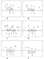
本発明の理解を容易にするために、計数境界16を横切る2人の人物の状況に、本発明の特定の一実施形態における処理を適用する。この状況の処理を、図15a〜図15fおよび図16を参照して下記に説明する。図15a〜図15fは、時間t0から時間t5までに取り込まれた6つの画像の画像系列を図説する。
To facilitate understanding of the present invention, the process in one particular embodiment of the present invention is applied to the situation of two persons crossing the counting
図15aでは、t0において、2人の人物50、52が近くで一緒に歩いているので、2人の人物50、52は、破線によって表示される1つの移動領域102として検出される。検出した移動領域102は、計数境界108にまだ達していないが、速度成分v0は、続く時間スライスdt以内に線に達するであろうことを指し示す。それゆえ、移動領域102が寄与ゾーンの範囲内であり、前の説明ではサブ面積とやはり呼ばれる瞬間的な面積フロー、dA0は、それゆえ、図16のグラフに図示したようにゼロではない。
In Figure 15a, at t 0, since two
ここで、t1における次のフレームを表す図15bを参照して、2人の人物50、52は、1つの移動領域102としてまだ検出されている。寄与ゾーンを、速度v1に基づいて計算する。移動領域102の一部が、ここでは計数境界を横切っており、新たな瞬間的な面積フロー、dA1を前に説明したように寄与ゾーンから生成する。寄与ゾーン内に存在する移動領域102の面積dA1は、図15bおよび図16の両方に見られるように、t0におけるよりもt1におけるほうが大きい。
Here, referring to FIG. 15 b representing the next frame at t 1 , the two
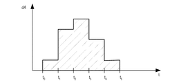
t=t2において取り込まれた画像を表す図15cでは、2人の人物50、52は互いに離れるように歩いており、それゆえさらに離れて歩いている。2人の人物50、52は、これゆえ、2つの別々の移動領域102a、102bとして検出され、2つの別々の瞬間的な面積フロー成分dA2aおよびdA2bを生成する。異なる面積フロー成分dA2aおよびdA2bを、各移動領域102a、102bの個々の速度を使用してそれぞれ計算する、すなわち、各移動領域102a、102bの個別の速度v2a、v2bに基づいて、各移動領域102a、102bがそれ自体の寄与ゾーンを用いて与えられる。この例では、v2a>v2bであり、それゆえ、速度v2bで進む移動領域102bに対してよりも速度v2aで動く移動領域102aに対して、より大きな寄与ゾーンを生成する。一実施形態によれば、時間スロットt2に対する合計の瞬間的な面積フローdA2を生成するために、2つの瞬間的な面積フロー成分dA2aおよびdA2bを、一緒に足し算する。別の一実施形態によれば、2つの瞬間的な面積フロー成分dA2aおよびdA2bを別々に記憶するか、または計数境界を横切った合計の面積フローAtotを指し示す積算した変数に別々に足し算する。
In Figure 15c represents the images captured at t = t 2, the two
時間t3においては、図15d参照、2人の人物50、52は、もう1度一緒に近づき、それによって、2人の人物50、52をカバーする1つの移動領域102を生成する。これゆえ、1つの瞬間的な面積フロー成分、dA3を生成する。
At time t 3 , see FIG. 15 d, the two
時間t4において取り込んだ画像では、図15e参照、2人の人物50、52に関係する移動領域についての最終の瞬間的な面積フロー成分、dA4を決定する。次に、時間t5において、2人の人物50、52は、計数境界16を完全に通過し、さらなる面積フロー成分が決定されないことがある。
For the image captured at time t 4 , see FIG. 15 e and determine the final instantaneous area flow component, dA 4 , for the moving region related to the two
上に論じたように、図16のグラフは、図15a〜図15fの画像系列から決定した瞬間的な面積フローまたはサブ面積を表しているグラフを示す。グラフの下方の面積は、画像系列から積算した面積と考えることができ、t0からt5までの積分した瞬間的な面積フロー、すなわち、合計面積Atotに対応するはずである。 As discussed above, the graph of FIG. 16 shows a graph representing the instantaneous area flow or sub-area determined from the image sequence of FIGS. 15a-15f. The area below the graph can be considered as an integrated area from the image series and should correspond to the integrated instantaneous area flow from t 0 to t 5 , ie, the total area A tot .
図15aでは、検出した移動領域102の一部が計数境界線16に達しない場合でさえ、移動領域102の面積の一部を記録することができることをさらに示している。移動領域102は、算出可能になる面積フロー寄与のためにそれ自体の寄与ゾーン内にある必要があるだけであり、寄与ゾーンのサイズは、前に論じたように移動領域102の速度に依存する。これゆえ、高速の測定対象物は、より大きな寄与ゾーンをもたらすであろう。面積フローを適正に算出するために、測定対象物計数器カメラの視野範囲内に全体の寄与ゾーンを完全に含有することが有利である。これを、計数する測定対象物に対する上限速度として知ることができる。
FIG. 15 a further illustrates that a portion of the area of the moving
10 カメラ
12 所定の計数ビュー
14 出口/入口
16 計数境界
18、20 人間
22 コンベヤベルト
24 測定対象物
26 測定対象物計数器
28 サーバ
30 パーソナルコンピュータ
32 ワークステーション
34 コンピュータネットワーク
50 人物
52 人物
102 移動領域
104 速度ベクトル
108、110 寄与線
600 レンズ
602 画像センサ
604 画像処理ユニット
606 処理ユニット
608 揮発性メモリ
610 不揮発性メモリ
612 ネットワークインターフェース
614 画像解析器
616 基準面積調節手段
618 測定対象物計数ユニット
620 移動領域検出器
622 寄与ゾーン計算器
624 面積計算器
626 面積積算器
DESCRIPTION OF
Claims (12)
所定の計数ビュー(12)の移動する画像を表す画像を取り込むステップと、
前記所定の計数ビュー(12)の前記移動する画像内の移動領域(102)を検出するステップと、
前記移動領域(102)の動きの速度を指し示す移動領域(102)速度値(va)を計算するステップと、
所定の計数境界(16)や、前記移動領域速度値(va)や、寄与時間間隔(dt)に基づいて寄与ゾーンを繰り返して規定するステップと、
前記規定した寄与ゾーン内に含有される前記移動領域(102)の面積のサイズを表すサブ面積値(dA)を繰り返して取り出し、記録するステップと、
複数の記録したサブ面積値(dA)を足し算することによって合計面積値(Atot)を生成するステップと、
前記合計面積値(Atot)を基準測定対象物面積値(Ano)で割り算することによって前記計数境界(16)を通過した測定対象物の数を推定するステップとを備え、
前記寄与時間間隔(dt)が、サブ面積値(dA)を取り出す2つの連続した行為間の時間間隔に対応する、方法。 A method for counting objects to be measured, the method comprising:
Capturing an image representing a moving image of a predetermined counting view (12);
Detecting a moving region (102) in the moving image of the predetermined counting view (12);
Calculating a moving region (102) speed value (va) indicating the speed of movement of the moving region (102);
A step of defining repeatedly contribution zone based predetermined counting boundary (16) and the moving region speed value (v a) and, on the contribution time interval (dt),
Repeatedly taking out and recording a sub-area value (dA) representing the size of the area of the moving region (102) contained within the defined contribution zone;
Generating a total area value (A tot ) by adding a plurality of recorded sub-area values (dA);
Estimating the number of measurement objects that have passed the counting boundary (16) by dividing the total area value (A tot ) by a reference measurement object area value (A no ),
The method wherein the contribution time interval (dt) corresponds to the time interval between two consecutive actions that take a sub-area value (dA).
所定の計数ビュー(12)の画像を取り込むために配置された画像センサ(602)と、
前記取り込んだ画像内の移動する領域(102)を検出し、前記移動領域(102)の動きの速度を指し示す速度値(va)を計算するために配置された移動領域検出器(620)と
を備えた測定対象物計数器において、
所定の計数境界(16)や、前記速度値(va)や、寄与時間間隔(dt)に基づいて寄与ゾーンを繰り返して規定するために配置された寄与ゾーン計算器(622)と、
前記規定した寄与ゾーン内に含有された前記移動領域(102)の面積のサイズを表すサブ面積値(dA)を取り出し、記録するために配置された面積計算器(624)と、
複数の記録したサブ面積値(dA)を足し算することによって合計面積値(Atot)を積算するために配置された面積積算器(626)と、
前記合計面積値(Atot)を基準測定対象物面積値(Ano)で割り算することによって前記計数境界(16)を通過した測定対象物の数を計算するために配置された測定対象物計数ユニット(618)と
を備えることを特徴とする、測定対象物計数器。 A measurement object counter for counting a measurement object that passes through the specified counting boundary (16), the measurement object counter comprising:
An image sensor (602) arranged to capture an image of a predetermined counting view (12);
A moving region detector (620) arranged to detect a moving region (102) in the captured image and calculate a velocity value (va) indicating the speed of movement of the moving region (102); In the measuring object counter with
Predetermined counting boundary (16) and the speed value (v a) and the contribution zone calculator which is arranged to define repeated contribution zone based on contribution time interval (dt) and (622),
An area calculator (624) arranged to retrieve and record a sub-area value (dA) representing the size of the area of the moving region (102) contained within the defined contribution zone;
An area accumulator (626) arranged to accumulate the total area value (A tot ) by adding a plurality of recorded sub-area values (dA);
A measurement object counting unit arranged to calculate the number of measurement objects that have passed the counting boundary (16) by dividing the total area value (A tot ) by a reference measurement object area value (A no ). 618). A measurement object counter.
Applications Claiming Priority (4)
| Application Number | Priority Date | Filing Date | Title |
|---|---|---|---|
| US41513410P | 2010-11-18 | 2010-11-18 | |
| US61/415,134 | 2010-11-18 | ||
| EP10191650.0 | 2010-11-18 | ||
| EP10191650A EP2455914B1 (en) | 2010-11-18 | 2010-11-18 | Object counter and method for counting objects |
Publications (2)
| Publication Number | Publication Date |
|---|---|
| JP2012108908A true JP2012108908A (en) | 2012-06-07 |
| JP5432227B2 JP5432227B2 (en) | 2014-03-05 |
Family
ID=43798345
Family Applications (1)
| Application Number | Title | Priority Date | Filing Date |
|---|---|---|---|
| JP2011245559A Active JP5432227B2 (en) | 2010-11-18 | 2011-11-09 | Measuring object counter and method for counting measuring objects |
Country Status (7)
| Country | Link |
|---|---|
| US (2) | US8699758B2 (en) |
| EP (1) | EP2455914B1 (en) |
| JP (1) | JP5432227B2 (en) |
| KR (1) | KR101556693B1 (en) |
| CN (1) | CN102467679B (en) |
| ES (1) | ES2396500T3 (en) |
| TW (1) | TWI508004B (en) |
Cited By (1)
| Publication number | Priority date | Publication date | Assignee | Title |
|---|---|---|---|---|
| JP2020518046A (en) * | 2017-04-21 | 2020-06-18 | インテグレイテッド デザイン リミテッド | An optical system that monitors the movement of a person through a passage |
Families Citing this family (28)
| Publication number | Priority date | Publication date | Assignee | Title |
|---|---|---|---|---|
| ES2396500T3 (en) | 2010-11-18 | 2013-02-22 | Axis Ab | Object counter and method for counting objects |
| KR101222482B1 (en) * | 2011-06-23 | 2013-01-15 | 브이씨에이 테크놀러지 엘티디 | People counter having set up interface and set up method thereof |
| US11288472B2 (en) | 2011-08-30 | 2022-03-29 | Digimarc Corporation | Cart-based shopping arrangements employing probabilistic item identification |
| JP5893417B2 (en) * | 2012-01-24 | 2016-03-23 | キヤノン株式会社 | Analysis device, control method, and program |
| NO335224B1 (en) | 2013-01-28 | 2014-10-20 | Sinvent As | Zooplankton counting system and method |
| DE102013207139A1 (en) * | 2013-04-19 | 2014-10-23 | Krones Ag | Method for monitoring and controlling a filling installation and device for carrying out the method |
| BR102013013365B1 (en) | 2013-05-29 | 2021-12-14 | Sicpa Brasil Indústria De Tintas E Sistemas Ltda | METHOD AND DEVICE FOR COUNTING OBJECTS TRANSPORTED ON A CONVEYOR BELT |
| KR101557376B1 (en) * | 2014-02-24 | 2015-10-05 | 에스케이 텔레콤주식회사 | Method for Counting People and Apparatus Therefor |
| US10460194B2 (en) * | 2014-03-07 | 2019-10-29 | Lior Wolf | System and method for the detection and counting of repetitions of repetitive activity via a trained network |
| TWI509212B (en) * | 2014-06-18 | 2015-11-21 | Nat Applied Res Laboratories | Item quantity estimation method |
| CN105825266B (en) * | 2016-05-22 | 2018-01-16 | 福建福贞金属包装有限公司 | Aluminum products seamless tin quantification line control method |
| US10140718B2 (en) | 2016-08-09 | 2018-11-27 | Qualcomm Incorporated | Methods and systems of maintaining object trackers in video analytics |
| US10810481B2 (en) * | 2017-01-11 | 2020-10-20 | Thomas Danaher Harvey | Method and system to count movements of persons from vibrations in a floor |
| US10839552B2 (en) * | 2017-06-01 | 2020-11-17 | Nec Corporation | Image processing apparatus, tracking method, and program |
| TWI679612B (en) * | 2018-08-14 | 2019-12-11 | 國立交通大學 | Image tracking method |
| CN112805582B (en) | 2018-08-24 | 2025-02-18 | 路创技术有限责任公司 | Occupant counting device |
| JP7303412B2 (en) * | 2018-08-30 | 2023-07-05 | シンフォニアテクノロジー株式会社 | Work count control system, parts feeder |
| JP2022011927A (en) * | 2020-06-30 | 2022-01-17 | キヤノン株式会社 | Information processing equipment, information processing methods, and programs |
| DE102021104623B4 (en) * | 2021-02-26 | 2024-08-29 | Ssi Schäfer Automation Gmbh (At) | Material flow control with virtual sensors |
| US11676383B2 (en) | 2021-03-15 | 2023-06-13 | Sensormatic Electronics, LLC | Object counting system for high volume traffic |
| US11676384B2 (en) * | 2021-03-15 | 2023-06-13 | Sensormatic Electronics, LLC | Object counting system for high volume traffic |
| WO2023015029A1 (en) * | 2021-08-06 | 2023-02-09 | Illinois Tool Works Inc. | Vision sensor infeed system |
| US12054344B2 (en) | 2021-08-06 | 2024-08-06 | Illinois Tool Works Inc. | Vision sensor infeed system |
| CN113709006B (en) * | 2021-10-29 | 2022-02-08 | 上海闪马智能科技有限公司 | Flow determination method and device, storage medium and electronic device |
| TW202319957A (en) * | 2021-11-05 | 2023-05-16 | 華捷智能股份有限公司 | Image recognition system and image recognition method |
| KR102673628B1 (en) | 2022-12-29 | 2024-06-13 | 주식회사 심시스글로벌 | Method and apparatus for monitoring crowd density based on map cell for situational awareness in digital twin |
| CN116451734B (en) * | 2023-06-19 | 2023-09-29 | 浙江托普云农科技股份有限公司 | Auxiliary high-precision seed counting method, system, device and readable storage medium |
| KR102685315B1 (en) * | 2023-10-25 | 2024-07-16 | 주식회사 포딕스시스템 | Event detection system based on motion region using motion vectors in video and method thereof |
Citations (4)
| Publication number | Priority date | Publication date | Assignee | Title |
|---|---|---|---|---|
| JPH1048008A (en) * | 1996-08-02 | 1998-02-20 | Omron Corp | Attention information measuring method and apparatus, and various systems using the same |
| JPH11282999A (en) * | 1998-03-30 | 1999-10-15 | East Japan Railway Co | Moving object measurement device |
| JP2002074371A (en) * | 2000-08-31 | 2002-03-15 | Mitsubishi Electric Corp | Image processing device |
| JP2005326966A (en) * | 2004-05-12 | 2005-11-24 | Mitsubishi Electric Corp | People counting device |
Family Cites Families (14)
| Publication number | Priority date | Publication date | Assignee | Title |
|---|---|---|---|---|
| EP0700017B1 (en) * | 1994-08-31 | 2001-11-07 | Nippon Telegraph And Telephone Corporation | Method and apparatus for directional counting of moving objects |
| US7596241B2 (en) | 2005-06-30 | 2009-09-29 | General Electric Company | System and method for automatic person counting and detection of specific events |
| US8224026B2 (en) | 2005-12-08 | 2012-07-17 | Lenel Systems International, Inc. | System and method for counting people near external windowed doors |
| TW200727204A (en) * | 2006-01-06 | 2007-07-16 | Univ Nat Kaohsiung Applied Sci | Bi-directional people counter for pedestrian passing flow |
| CN201063168Y (en) * | 2007-01-23 | 2008-05-21 | 联策科技股份有限公司 | Optical counting device |
| WO2009016614A2 (en) | 2007-08-02 | 2009-02-05 | Emza Visual Sense Ltd. | Universal counting and measurement system |
| TWM327060U (en) * | 2007-08-21 | 2008-02-11 | Taiwan Leading Biotech Inc | Image analysis counting system for use in aquaculture technology field |
| WO2009039350A1 (en) | 2007-09-19 | 2009-03-26 | Micro Target Media Holdings Inc. | System and method for estimating characteristics of persons or things |
| TWI372359B (en) * | 2008-03-21 | 2012-09-11 | Huper Lab Co Ltd | Vertical people monitoring and counting method |
| US20090296989A1 (en) | 2008-06-03 | 2009-12-03 | Siemens Corporate Research, Inc. | Method for Automatic Detection and Tracking of Multiple Objects |
| EP2310981B1 (en) | 2008-07-08 | 2012-01-04 | Nortech International (PTY) Limited | Apparatus and method of classifying movement of objects in a monitoring zone |
| US8121424B2 (en) | 2008-09-26 | 2012-02-21 | Axis Ab | System, computer program product and associated methodology for video motion detection using spatio-temporal slice processing |
| ES2396500T3 (en) | 2010-11-18 | 2013-02-22 | Axis Ab | Object counter and method for counting objects |
| TWI448977B (en) * | 2011-12-08 | 2014-08-11 | Ind Tech Res Inst | Method and apparatus for video analytics based object counting |
-
2010
- 2010-11-18 ES ES10191650T patent/ES2396500T3/en active Active
- 2010-11-18 EP EP10191650A patent/EP2455914B1/en active Active
-
2011
- 2011-09-27 TW TW100134878A patent/TWI508004B/en active
- 2011-10-18 KR KR1020110106488A patent/KR101556693B1/en active Active
- 2011-11-09 JP JP2011245559A patent/JP5432227B2/en active Active
- 2011-11-14 CN CN201110360114.3A patent/CN102467679B/en active Active
- 2011-11-15 US US13/296,708 patent/US8699758B2/en active Active
-
2014
- 2014-02-24 US US14/187,600 patent/US9177385B2/en active Active
Patent Citations (4)
| Publication number | Priority date | Publication date | Assignee | Title |
|---|---|---|---|---|
| JPH1048008A (en) * | 1996-08-02 | 1998-02-20 | Omron Corp | Attention information measuring method and apparatus, and various systems using the same |
| JPH11282999A (en) * | 1998-03-30 | 1999-10-15 | East Japan Railway Co | Moving object measurement device |
| JP2002074371A (en) * | 2000-08-31 | 2002-03-15 | Mitsubishi Electric Corp | Image processing device |
| JP2005326966A (en) * | 2004-05-12 | 2005-11-24 | Mitsubishi Electric Corp | People counting device |
Cited By (2)
| Publication number | Priority date | Publication date | Assignee | Title |
|---|---|---|---|---|
| JP2020518046A (en) * | 2017-04-21 | 2020-06-18 | インテグレイテッド デザイン リミテッド | An optical system that monitors the movement of a person through a passage |
| JP7156588B2 (en) | 2017-04-21 | 2022-10-19 | インテグレイテッド デザイン リミテッド | An optical system that monitors the movement of people through corridors |
Also Published As
| Publication number | Publication date |
|---|---|
| US8699758B2 (en) | 2014-04-15 |
| CN102467679B (en) | 2016-02-24 |
| US9177385B2 (en) | 2015-11-03 |
| TW201227543A (en) | 2012-07-01 |
| CN102467679A (en) | 2012-05-23 |
| EP2455914B1 (en) | 2012-10-17 |
| EP2455914A1 (en) | 2012-05-23 |
| TWI508004B (en) | 2015-11-11 |
| KR20120053949A (en) | 2012-05-29 |
| KR101556693B1 (en) | 2015-10-13 |
| ES2396500T3 (en) | 2013-02-22 |
| US20120128212A1 (en) | 2012-05-24 |
| US20140185876A1 (en) | 2014-07-03 |
| JP5432227B2 (en) | 2014-03-05 |
Similar Documents
| Publication | Publication Date | Title |
|---|---|---|
| JP5432227B2 (en) | Measuring object counter and method for counting measuring objects | |
| US9846811B2 (en) | System and method for video-based determination of queue configuration parameters | |
| US7692684B2 (en) | People counting systems and methods | |
| US20180061161A1 (en) | Information processing apparatus, information processing method, and storage medium | |
| JP6969871B2 (en) | Movement status estimation device, movement status estimation method and program | |
| US7400745B2 (en) | Systems and methods for determining if objects are in a queue | |
| US20160191865A1 (en) | System and method for estimating an expected waiting time for a person entering a queue | |
| JP6270433B2 (en) | Information processing apparatus, information processing method, and information processing system | |
| JP6120404B2 (en) | Mobile body behavior analysis / prediction device | |
| US20120207350A1 (en) | Apparatus for identification of an object queue, method and computer program | |
| US10606668B2 (en) | Determining information relating to occupancy of a space | |
| US10902355B2 (en) | Apparatus and method for processing information and program for the same | |
| US10902639B2 (en) | Information processing apparatus, information processing method, and program | |
| KR20160041441A (en) | Method for detecting human-object using depth camera and device | |
| EP3179453B1 (en) | Queue monitoring based on imprint profiles | |
| JP2015185106A (en) | People counting device, people counting system, and people counting method | |
| US20230154192A1 (en) | Person flow analysis method and system, electronic device, and readable storage medium | |
| JP2011232864A (en) | Facility information classification system and facility information classification program | |
| JP6733766B1 (en) | Analysis device, control method, and program | |
| JP6866950B2 (en) | Analyzer, control method, and program | |
| JP2019133432A (en) | In-store monitoring device, in-store monitoring method, and in-store monitoring program | |
| JPWO2019188079A1 (en) | Person transit time measurement system and person transit time measurement method | |
| CN110956644A (en) | A kind of motion trajectory determination method and system | |
| JP2024102674A (en) | Setting device, counting system, setting method, and program | |
| JP2023163079A (en) | Image processing apparatus, image processing method, and program |
Legal Events
| Date | Code | Title | Description |
|---|---|---|---|
| A977 | Report on retrieval |
Free format text: JAPANESE INTERMEDIATE CODE: A971007 Effective date: 20121221 |
|
| A131 | Notification of reasons for refusal |
Free format text: JAPANESE INTERMEDIATE CODE: A131 Effective date: 20130122 |
|
| A521 | Request for written amendment filed |
Free format text: JAPANESE INTERMEDIATE CODE: A523 Effective date: 20130412 |
|
| TRDD | Decision of grant or rejection written | ||
| A01 | Written decision to grant a patent or to grant a registration (utility model) |
Free format text: JAPANESE INTERMEDIATE CODE: A01 Effective date: 20131119 |
|
| A61 | First payment of annual fees (during grant procedure) |
Free format text: JAPANESE INTERMEDIATE CODE: A61 Effective date: 20131205 |
|
| R150 | Certificate of patent or registration of utility model |
Free format text: JAPANESE INTERMEDIATE CODE: R150 Ref document number: 5432227 Country of ref document: JP Free format text: JAPANESE INTERMEDIATE CODE: R150 |
|
| R250 | Receipt of annual fees |
Free format text: JAPANESE INTERMEDIATE CODE: R250 |
|
| R250 | Receipt of annual fees |
Free format text: JAPANESE INTERMEDIATE CODE: R250 |
|
| R250 | Receipt of annual fees |
Free format text: JAPANESE INTERMEDIATE CODE: R250 |
|
| R250 | Receipt of annual fees |
Free format text: JAPANESE INTERMEDIATE CODE: R250 |
|
| R250 | Receipt of annual fees |
Free format text: JAPANESE INTERMEDIATE CODE: R250 |
|
| R250 | Receipt of annual fees |
Free format text: JAPANESE INTERMEDIATE CODE: R250 |
|
| R250 | Receipt of annual fees |
Free format text: JAPANESE INTERMEDIATE CODE: R250 |
|
| R250 | Receipt of annual fees |
Free format text: JAPANESE INTERMEDIATE CODE: R250 |
|
| R250 | Receipt of annual fees |
Free format text: JAPANESE INTERMEDIATE CODE: R250 |