JP2012109199A - Fuel cell stack with water drainage structure - Google Patents
Fuel cell stack with water drainage structure Download PDFInfo
- Publication number
- JP2012109199A JP2012109199A JP2011086329A JP2011086329A JP2012109199A JP 2012109199 A JP2012109199 A JP 2012109199A JP 2011086329 A JP2011086329 A JP 2011086329A JP 2011086329 A JP2011086329 A JP 2011086329A JP 2012109199 A JP2012109199 A JP 2012109199A
- Authority
- JP
- Japan
- Prior art keywords
- plate
- stack
- cathode
- anode
- dummy
- Prior art date
- Legal status (The legal status is an assumption and is not a legal conclusion. Google has not performed a legal analysis and makes no representation as to the accuracy of the status listed.)
- Granted
Links
Images



Classifications
-
- H—ELECTRICITY
- H01—ELECTRIC ELEMENTS
- H01M—PROCESSES OR MEANS, e.g. BATTERIES, FOR THE DIRECT CONVERSION OF CHEMICAL ENERGY INTO ELECTRICAL ENERGY
- H01M8/00—Fuel cells; Manufacture thereof
- H01M8/04—Auxiliary arrangements, e.g. for control of pressure or for circulation of fluids
- H01M8/04082—Arrangements for control of reactant parameters, e.g. pressure or concentration
- H01M8/04089—Arrangements for control of reactant parameters, e.g. pressure or concentration of gaseous reactants
- H01M8/04119—Arrangements for control of reactant parameters, e.g. pressure or concentration of gaseous reactants with simultaneous supply or evacuation of electrolyte; Humidifying or dehumidifying
- H01M8/04156—Arrangements for control of reactant parameters, e.g. pressure or concentration of gaseous reactants with simultaneous supply or evacuation of electrolyte; Humidifying or dehumidifying with product water removal
-
- H—ELECTRICITY
- H01—ELECTRIC ELEMENTS
- H01M—PROCESSES OR MEANS, e.g. BATTERIES, FOR THE DIRECT CONVERSION OF CHEMICAL ENERGY INTO ELECTRICAL ENERGY
- H01M8/00—Fuel cells; Manufacture thereof
- H01M8/24—Grouping of fuel cells, e.g. stacking of fuel cells
- H01M8/2465—Details of groupings of fuel cells
-
- H—ELECTRICITY
- H01—ELECTRIC ELEMENTS
- H01M—PROCESSES OR MEANS, e.g. BATTERIES, FOR THE DIRECT CONVERSION OF CHEMICAL ENERGY INTO ELECTRICAL ENERGY
- H01M8/00—Fuel cells; Manufacture thereof
- H01M8/24—Grouping of fuel cells, e.g. stacking of fuel cells
- H01M8/2465—Details of groupings of fuel cells
- H01M8/2483—Details of groupings of fuel cells characterised by internal manifolds
-
- H—ELECTRICITY
- H01—ELECTRIC ELEMENTS
- H01M—PROCESSES OR MEANS, e.g. BATTERIES, FOR THE DIRECT CONVERSION OF CHEMICAL ENERGY INTO ELECTRICAL ENERGY
- H01M8/00—Fuel cells; Manufacture thereof
- H01M8/10—Fuel cells with solid electrolytes
- H01M2008/1095—Fuel cells with polymeric electrolytes
-
- Y—GENERAL TAGGING OF NEW TECHNOLOGICAL DEVELOPMENTS; GENERAL TAGGING OF CROSS-SECTIONAL TECHNOLOGIES SPANNING OVER SEVERAL SECTIONS OF THE IPC; TECHNICAL SUBJECTS COVERED BY FORMER USPC CROSS-REFERENCE ART COLLECTIONS [XRACs] AND DIGESTS
- Y02—TECHNOLOGIES OR APPLICATIONS FOR MITIGATION OR ADAPTATION AGAINST CLIMATE CHANGE
- Y02E—REDUCTION OF GREENHOUSE GAS [GHG] EMISSIONS, RELATED TO ENERGY GENERATION, TRANSMISSION OR DISTRIBUTION
- Y02E60/00—Enabling technologies; Technologies with a potential or indirect contribution to GHG emissions mitigation
- Y02E60/30—Hydrogen technology
- Y02E60/50—Fuel cells
Landscapes
- Life Sciences & Earth Sciences (AREA)
- Engineering & Computer Science (AREA)
- Manufacturing & Machinery (AREA)
- Sustainable Development (AREA)
- Sustainable Energy (AREA)
- Chemical & Material Sciences (AREA)
- Chemical Kinetics & Catalysis (AREA)
- Electrochemistry (AREA)
- General Chemical & Material Sciences (AREA)
- Fuel Cell (AREA)
Abstract
【課題】効果的に凝縮水を排出できる燃料電池スタックを提供する。
【解決手段】水排出構造を有する燃料電池スタックは、複数のセルがスタック両端のエンドプレート3の間に積層された燃料電池スタックであって、スタック発電部のエンドセルと上記両端のエンドプレートとの間にはスタックの水排出のためのダミーセルとしてカソードダミーセル(CD)とアノードダミーセル(AD)がそれぞれ少なくとも一側に1つ以上積層され、カソードダミーセル(CD)は、カソードプレート20及びエンドアノードプレート100分離板を含んで形成され、アノードダミーセル(AD)は、アノードプレート10及びエンドカソードプレート200分離板を含んで形成される。
【選択図】図1A fuel cell stack capable of effectively discharging condensed water is provided.
A fuel cell stack having a water discharge structure is a fuel cell stack in which a plurality of cells are stacked between end plates 3 at both ends of the stack, and includes an end cell of a stack power generation unit and the end plates at both ends. One or more cathode dummy cells (CD) and anode dummy cells (AD) are stacked on at least one side as dummy cells for discharging water from the stack. The cathode dummy cells (CD) include the cathode plate 20 and the end anode plate 100. The anode dummy cell (AD) is formed including the anode plate 10 and the end cathode plate 200 separator.
[Selection] Figure 1
Description
本発明は、水排出構造を有する燃料電池スタックに係り、より詳しくは、従来のアノードプレート(AP)及びカソードプレート(CP)を簡単に変形したエンドアノードプレート(EAP)及びエンドカソードプレート(ECP)を上記カソードプレート(CP)及びアノードプレート(AP)と組み合わせてダミーセルを構成し、上記ダミーセルをエンドセル部に位置させるという簡単な構成により効果的に凝縮水を排出し、セルへの水の流入を最小化できる水排出構造を有する燃料電池スタックに関する。 The present invention relates to a fuel cell stack having a water discharge structure, and more particularly, an end anode plate (EAP) and an end cathode plate (ECP) obtained by simply modifying a conventional anode plate (AP) and cathode plate (CP). Is combined with the cathode plate (CP) and the anode plate (AP) to form a dummy cell, and the condensed cell is effectively discharged by a simple configuration in which the dummy cell is positioned in the end cell portion, and the inflow of water into the cell is prevented. The present invention relates to a fuel cell stack having a water discharge structure that can be minimized.
燃料電池は、燃料が持っている化学エネルギを燃焼により熱に変えるのではなく、燃料電池スタック内で電気化学的に反応させて電気エネルギーに変換させる一種の発電装置であり、産業用、家庭用、及び車両駆動用電力を供給するだけでなく、小型の電気/電子製品、特に携帯用装置の電力供給にも適用される。
このような燃料電池において、車両駆動のための電力供給源として最も多く研究されている高分子電解質膜燃料電池(PEMFC:Polymer Electrolyte Membrane Fuel Cell、Proton Exchange Membrane Fuel Cell)は、水素イオンが移動する電解質膜を中心として膜の両側に電気化学反応が起こる触媒電極層が付着された膜電極接合体(MEA:Membrane Electrode Assembly)、反応基体を均一に分布させ、発生した電気エネルギーを伝達する役割を担う気体拡散層(GDL:Gas Diffusion Layer)、反応基体及び冷却水の気密性と適正締結圧を維持するためのガスケット、及び締結器具、そして反応基体及び冷却水を移動させる分離板(BP:Bipolar Plate)を含んで構成される。
A fuel cell is a type of power generation device that does not convert chemical energy contained in fuel into heat by combustion, but instead reacts it electrochemically in the fuel cell stack to convert it into electrical energy. In addition to supplying electric power for driving a vehicle, the present invention is also applied to electric power supply for small electric / electronic products, particularly portable devices.
In such a fuel cell, a polymer electrolyte membrane fuel cell (PEMFC: Polymer Electron Fuel Cell, Proton Exchange Membrane Fuel Cell), which is most studied as a power supply source for driving a vehicle, moves hydrogen ions. Membrane Electrode Assembly (MEA) with a catalyst electrode layer that causes an electrochemical reaction on both sides of the membrane centering on the electrolyte membrane, and the role of uniformly distributing the reaction substrate and transmitting the generated electrical energy Gas diffusion layer (GDL) to be carried, gasket for maintaining airtightness and proper fastening pressure of reaction substrate and cooling water, fastening device, and movement of reaction substrate and cooling water Thereby separating plate (BP: Bipolar Plate) configured to include a.
この時、上記分離板(BP)は、水素が供給される流路が形成されたアノードプレート(AP:Anode Plate)と、酸素を含む空気が供給される流路が形成されたカソードプレート(CP:Cathode Plate)に分けられる。
上記燃料電池において、燃料である水素と酸化剤である酸素(空気)は、それぞれアノードプレート(AP)とカソードプレート(CP)の流路を介して膜電極接合体のアノード(anode)とカソード(cathode)に供給される。アノードに供給された水素は電解質膜の両側に構成された電極層の触媒により、水素イオン(proton、H+)と電子(electron、e−)に分解され、このうち、水素イオンのみが選択的に陽イオン交換膜である電解質膜を通過してカソードに伝達され、同時に電子は導体である気体拡散層と分離板を介してカソードに伝達される。
At this time, the separation plate (BP) includes an anode plate (AP) in which a flow path for supplying hydrogen is formed, and a cathode plate (CP) in which a flow path for supplying air containing oxygen is formed. : Cathode Plate).
In the fuel cell, hydrogen as the fuel and oxygen (air) as the oxidant are passed through the anode plate (AP) and the cathode plate (CP), respectively, and the anode (anode) and cathode (anode) of the membrane electrode assembly. cathode). Hydrogen supplied to the anode is decomposed into hydrogen ions (proton, H + ) and electrons (electron, e − ) by the catalyst of the electrode layer formed on both sides of the electrolyte membrane. Among these, only hydrogen ions are selectively used. Then, it passes through the electrolyte membrane, which is a cation exchange membrane, and is transmitted to the cathode, and at the same time, the electrons are transmitted to the cathode through a gas diffusion layer and a separator as conductors.
上記カソードでは電解質膜を介して供給された水素イオンと分離板を介して伝達された電子が、空気供給装置によりカソードに供給された空気中の酸素と反応して水を生成する。この時、発生する水素イオンの移動に起因して外部導線を通した電子の流れが発生し、このような電子の流れにより電流が生成される。
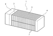
図5は、一般的な燃料電池スタック1の一例を示しており、図6は、上記スタックに使用される分離板(BP)のうちの1つであるアノードプレート(AP)10を示している。
In the cathode, hydrogen ions supplied through the electrolyte membrane and electrons transmitted through the separation plate react with oxygen in the air supplied to the cathode by the air supply device to generate water. At this time, an electron flow through the external conductor is generated due to the movement of the generated hydrogen ions, and an electric current is generated by the electron flow.
FIG. 5 shows an example of a general
車両用燃料電池スタック1は、複数のセル5が直列に連結される構造であり、発電に必要な空気及び水素が、図5に示すように、スタック1の一方の端部から供給及び排出される構造を有してもよい。
すなわち、空気及び水素が共用分配器2を介してマニホールドの孔があけられたオープンエンドプレート(open EP)3に流入されてスタック発電部7を循環した後、再びオープンエンドプレート3を介して排出される。ここで、カソード循環(Cathode loop)の場合、加湿器(図示せず)を介してスタック1に供給された空気がスタック1を通過し再び加湿器を介して車両外部に排出される。また、アノード循環(Anode loop)の場合、水素タンク(図示せず)から供給された水素が水素供給システム(FPS、図示せず)を介してスタック1に供給され、スタック1から排出された残余水素はFPSとスタックとの間を循環し続ける。
The vehicle
That is, air and hydrogen flow into the open end plate (open EP) 3 with a hole in the manifold via the shared
上記スタック発電部7のそれぞれのセル5は、アノードプレート(AP)−気体拡散層(GDL)−膜電極接合体(MEA)−気体拡散層(GDL)−カソードプレート(CP)の積層構造を有するが、上記アノードプレート10及びカソードプレートは、図6に示すように、水素、冷却水、及び空気がそれぞれ通過するマニホールド12,14,16を両端に備えている。
この時、上記アノードプレート10には、図6に示すように、水素マニホールド12と連通する水素入口/出口ホール13が形成されており、上記アノードプレートのセル反応面に形成された水素流路15を介して水素が通過する。
Each
At this time, as shown in FIG. 6, the
上記アノードプレート10の外郭及びマニホールド12,14,16の外郭を囲むガスケット18は、上記マニホールド12,14,16及び水素流路15を通過する各流体の気密性を維持し、水素マニホールド12を通過する水素だけ上記水素入口/出口ホール13を介して水素流路15を通過することができる。また、カソードプレートには、上記原理と同様に、空気マニホールドと連通する空気入口/出口ホールが形成されており、上記カソードプレートのセル反応面に形成された空気流路を介して空気が通過する。
A
一方、上記のような燃料電池スタックの循環過程において、スタック発電部のカソード入口(Cathode IN)側には、加湿器−共用分配器−エンドプレート−スタック(分離板)マニホールドを介して凝縮水などが流入し、アノード入口(Anode IN)側には、FPS−共用分配器−エンドプレート−スタック(分離板)マニホールドを介して凝縮水と、カソードからMEA膜を介して水が流入する。
このような場合、流入した水は、オープンエンドプレート3に接する最外郭セルに流入するため、セル電圧の急激な下降/上昇の繰り返し、セル内部に存在する多量の水によるMEA触媒劣化を起こす。このような現象は、閉ループ(Closed Loop)で構成されたアノード循環(Anode loop)ではさらに深刻である。また、マニホールドの孔のないクローズエンドプレート(close EP)4の近くの最外郭セルは、分離板のインレットマニホールドを介して水素や空気が供給される時、スタックの長手方向のマニホールドで凝縮された水が上記クローズエンドプレート4側に偏って最外郭セルに流入する。
On the other hand, in the circulation process of the fuel cell stack as described above, on the cathode inlet (Cathode IN) side of the stack power generation unit, condensed water or the like is provided via a humidifier-shared distributor-end plate-stack (separation plate) manifold. Flows into the anode inlet (Anode IN) side through the FPS-shared distributor-end plate-stack (separation plate) manifold and water flows from the cathode through the MEA membrane.
In such a case, since the inflowing water flows into the outermost cell in contact with the
セル内部のMEAを加湿する水分以外の凝縮水をスタック内部で除去することは、燃料電池車両の性能安定性及び耐久性に対する非常に重要な技術的課題である。このために、従来、車両の運転/制御技術やウォータータラップ(water trap)などを設けて水を除去したが、完全に水を除去することは困難である。
特許文献1では、スタック発電部の終端(エンドセル及びエンドプレート)部分にバイパスプレート(bypass plate)と中間プレート(intermediate plate)の構造を別に構成し、水素や空気がスタック発電部に供給される時、共に注がれる凝縮水などが発電部に流入せず、スタックの外部に排出される構成を提示した。しかしながら、上記特許の構成では、スタックの構成部品にバイパスプレート(bypass plate)と中間プレート(intermediate plate)を別に開発及び製作しなければならず、スタックの全体的な部品構成が複雑になる短所がある。
It is a very important technical problem for the performance stability and durability of a fuel cell vehicle to remove condensed water other than moisture that humidifies the MEA inside the cell. For this reason, conventionally, water is removed by providing a vehicle operation / control technique, a water trap, or the like, but it is difficult to completely remove the water.
In
本発明は、上記技術的課題解決のためになされたものであり、従来の燃料電池スタックを構成するセル構造とほぼ同様の構成を組み合わせてエンドセル部に位置させるという簡単な構成により効果的に凝縮水を排出できる燃料電池スタックを提供することにその目的がある。 The present invention has been made to solve the above technical problem, and is effectively condensed by a simple configuration in which a configuration similar to that of a conventional fuel cell stack is combined and positioned in the end cell portion. The object is to provide a fuel cell stack capable of draining water.
上記目的を達成するために本発明に係る水排出構造を有する燃料電池スタックは、複数のセルがスタック両端のエンドプレート(EP)の間に積層された燃料電池スタックであって、スタック発電部のエンドセルと上記両端のエンドプレート(EP)との間にはスタックの水排出のためのダミーセルとしてカソードダミーセル(CD)とアノードダミーセル(AD)がそれぞれ少なくとも一側に1つ以上積層されることを特徴とする。 To achieve the above object, a fuel cell stack having a water discharge structure according to the present invention is a fuel cell stack in which a plurality of cells are stacked between end plates (EP) at both ends of the stack, One or more cathode dummy cells (CD) and anode dummy cells (AD) are stacked on at least one side as dummy cells for discharging water from the stack between the end cells and the end plates (EP) at both ends. And
この時、上記カソードダミーセル(CD)は、カソードプレート(CP)及びエンドアノードプレート(EAP)分離板を含んで形成され、上記アノードダミーセル(AD)は、アノードプレート(AP)及びエンドカソードプレート(ECP)分離板を含んで形成されることを特徴とする。 At this time, the cathode dummy cell (CD) includes a cathode plate (CP) and an end anode plate (EAP) separator, and the anode dummy cell (AD) includes an anode plate (AP) and an end cathode plate (ECP). ) It is formed including a separation plate.
本発明の実施例で、上記エンドアノードプレート(EAP)は、アノードプレート(AP)の水素入口/出口ホールが除去されて形成され、上記エンドカソードプレート(ECP)は、カソードプレート(CP)の空気入口/出口ホールが除去されて形成されることを特徴とする。 In an embodiment of the present invention, the end anode plate (EAP) is formed by removing the hydrogen inlet / outlet holes of the anode plate (AP), and the end cathode plate (ECP) is the air of the cathode plate (CP). The entrance / exit hole is formed by being removed.
また、上記カソードダミーセル(CD)のカソードプレート(CP)とエンドアノードプレート(EAP)との間と、上記アノードダミーセル(AD)のアノードプレート(AP)とエンドカソードプレート(ECP)との間には、気体拡散層(GDL)をさらに含むことが好ましい。 Further, between the cathode plate (CP) and the end anode plate (EAP) of the cathode dummy cell (CD) and between the anode plate (AP) and the end cathode plate (ECP) of the anode dummy cell (AD). It is preferable that a gas diffusion layer (GDL) is further included.
また、上記カソードダミーセル(CD)及びアノードダミーセル(AD)は、膜電極接合体(MEA)を含まず、2つの気体拡散層(GDL)が互いに接合して積層されてもよい。 The cathode dummy cell (CD) and anode dummy cell (AD) do not include a membrane electrode assembly (MEA), and two gas diffusion layers (GDL) may be bonded to each other and stacked.
本発明の実施例によれば、上記エンドセルまたはダミーセルがスタック両端のエンドプレート(EP)に接する面には、ダミーエンドプレートとしてエンドカソードプレート(ECP)またはエンドアノードプレート(EAP)がさらに積層されることを特徴とする。 According to the embodiment of the present invention, an end cathode plate (ECP) or an end anode plate (EAP) is further laminated as a dummy end plate on the surface where the end cell or dummy cell contacts the end plates (EP) at both ends of the stack. It is characterized by that.
また、スタック両端のエンドプレート(EP)と上記ダミーエンドプレートとの間には気体拡散層(GDL)がさらに積層されることを特徴とする。 In addition, a gas diffusion layer (GDL) is further laminated between the end plates (EP) at both ends of the stack and the dummy end plates.
本発明に係る水排出構造を有する燃料電池スタックによれば、エンドアノードプレート(EAP)及びエンドカソードプレート(ECP)を通常のカソードプレート(CP)及びアノードプレート(AP)と組み合わせてダミーセルを構成し、上記ダミーセルをエンドセル部に位置させることにより効果的に凝縮水を排出でき、スタックセルへの水の流入を最小化することができる。
また、本発明に使用されるエンドアノードプレート(EAP)及びエンドカソードプレート(ECP)は、従来のアノードプレート(AP)及びカソードプレート(CP)で水素(または空気)入口/出口ホールのみ除去したものであり、従来のアノードプレート及びカソードプレートの成形工程において、水素(空気)入口/出口ホールを製作するパンチング過程を省略して製作できるため、製作工程が簡単であり、製作設備の追加が不要であるため費用を節減することができる。
According to the fuel cell stack having a water discharge structure according to the present invention, a dummy cell is configured by combining an end anode plate (EAP) and an end cathode plate (ECP) with a normal cathode plate (CP) and an anode plate (AP). By positioning the dummy cell in the end cell portion, the condensed water can be effectively discharged, and the inflow of water into the stack cell can be minimized.
In addition, the end anode plate (EAP) and end cathode plate (ECP) used in the present invention are obtained by removing only the hydrogen (or air) inlet / outlet holes with the conventional anode plate (AP) and cathode plate (CP). In the conventional anode plate and cathode plate forming process, the punching process for manufacturing the hydrogen (air) inlet / outlet holes can be omitted, so the manufacturing process is simple and no additional manufacturing equipment is required. This can save money.
以下、添付した図面を参照して本発明の好ましい実施例を詳細に説明する。
図1は、本発明の一実施例に係る燃料電池スタックの積層構造を示し、図2は、本発明の実施例で使用されるエンドアノードプレート(EAP)の構成を示す。
本発明は、スタックに流入する凝縮水を効果的に排出するためにスタック発電部のエンドセルとスタック両端のエンドプレート(EP)との間に積層されるダミーセルを含む。
通常のセル構造は、アノードプレート(AP)−気体拡散層(GDL)−膜電極接合体(MEA)−気体拡散層(GDL)−カソードプレート(CP)で構成されるが、本発明の実施例で使用されるダミーセルは、カソードプレート(CP)−エンドアノードプレート(EAP)を含むカソードダミーセルまたはアノードプレート(AP)−エンドカソードプレート(ECP)を含むアノードダミーセルで構成される。
Hereinafter, exemplary embodiments of the present invention will be described in detail with reference to the accompanying drawings.
FIG. 1 shows a stacked structure of a fuel cell stack according to an embodiment of the present invention, and FIG. 2 shows a configuration of an end anode plate (EAP) used in the embodiment of the present invention.
The present invention includes dummy cells stacked between the end cells of the stack power generation unit and the end plates (EP) at both ends of the stack in order to effectively discharge the condensed water flowing into the stack.
The normal cell structure is composed of anode plate (AP) -gas diffusion layer (GDL) -membrane electrode assembly (MEA) -gas diffusion layer (GDL) -cathode plate (CP). The dummy cell used in (1) is composed of a cathode dummy cell including a cathode plate (CP) -end anode plate (EAP) or an anode dummy cell including an anode plate (AP) -end cathode plate (ECP).
本発明で使用されるエンドアノードプレート(EAP)とエンドカソードプレート(ECP)は、従来のアノードプレート(AP)及びカソードプレート(CP)から水素入口/出口ホールと空気入口/出口ホールを除去したものである。 図2に示す通り、本発明の実施例に係るエンドアノードプレート100は、両端に水素マニホールド120、冷却水マニホールド140、及び空気マニホールド160を備えており、従来のアノードプレート(AP)と同一の形状で製作される。
ただし、エンドアノードプレート100は、水素マニホールド120と連通する水素入口/出口ホールを備えていないため、水素マニホールド120を通過する水素気体がガスケット180により遮断され、エンドアノードプレート100のセル反応面に流入することはない。また、本発明の実施例に係るエンドカソードプレート(ECP)も空気マニホールドと連通する空気入口/出口ホールを備えていないため、空気マニホールドを通過する空気が上記エンドカソードプレート(ECP)のセル反応面に流入することはない。
End anode plate (EAP) and end cathode plate (ECP) used in the present invention are obtained by removing hydrogen inlet / outlet holes and air inlet / outlet holes from the conventional anode plate (AP) and cathode plate (CP). It is. As shown in FIG. 2, the
However, since the
本発明の実施例に係るダミーセルは、化学反応を行わず、水排出のために積層されるセルであって、上記エンドアノードプレート(EAP)またはエンドカソードプレート(ECP)を含んで構成される。すなわち、アノードの水排出のためのアノードダミーセル(ED)は、アノードプレート(AP)とエンドカソードプレート(ECP)を含んで構成され、カソードの水排出のためのカソードダミーセル(CD)は、カソードプレート(CP)とエンドアノードプレート(EAP)を含んで構成される。
上記アノードダミーセル(ED)には、アノードプレート(AP)を介して水素が流入するが、エンドカソードプレート(ECP)を介して空気が流入することはないため、燃料電池の化学反応が起こることがなく、アノードの水排出だけが行われる。同様に、上記カソードダミーセル(CD)には、カソードプレート(CP)を介して空気が流入するが、エンドアノードプレート(EAP)を介して水素気体が流入することはないため、燃料電池の化学反応が起こることがなく、カソードの水排出だけが行われる。
A dummy cell according to an embodiment of the present invention is a cell that is stacked for discharging water without performing a chemical reaction, and includes the above-described end anode plate (EAP) or end cathode plate (ECP). That is, the anode dummy cell (ED) for draining the anode water includes an anode plate (AP) and an end cathode plate (ECP), and the cathode dummy cell (CD) for draining the cathode water is the cathode plate. (CP) and an end anode plate (EAP).
Hydrogen flows into the anode dummy cell (ED) through the anode plate (AP), but air does not flow in through the end cathode plate (ECP), which may cause a chemical reaction of the fuel cell. Instead, only the anode water is discharged. Similarly, air flows into the cathode dummy cell (CD) through the cathode plate (CP), but hydrogen gas does not flow in through the end anode plate (EAP). Will not occur, and only water discharge from the cathode will occur.
一方、本発明の実施例において、上記カソードダミーセル(CD)のカソードプレート(CP)とエンドアノードプレート(EAP)との間には気体拡散層(GDL)をさらに含む。上記気体拡散層(GDL)は、分離板間の電気的接触を維持できるようにし、MEAが入らないカソードダミーセル(CD)に、ガスケットの圧縮後、セルの内部空間をその厚さに合わせて満たすことにより、構造的な安定性を維持させる。好ましくは、上記カソードダミーセル(CD)の内部には、2つの気体拡散層(GDL)が互いに接合された気体拡散層接合体(GG)が積層されるようにしてもよく、これによって、通常のセルの厚さに合わせて構造的安定性を維持することができる。上記気体拡散層(GDL)は、アノードダミーセル(AD)のアノードプレート(AD)とエンドカソードプレート(ECP)との間にも同様に積層することができる。 Meanwhile, in the embodiment of the present invention, a gas diffusion layer (GDL) is further included between the cathode plate (CP) and the end anode plate (EAP) of the cathode dummy cell (CD). The gas diffusion layer (GDL) can maintain electrical contact between the separator plates, and fills the cathode dummy cell (CD) where the MEA does not enter after filling the internal space of the cell to the thickness after compression of the gasket. Thereby maintaining structural stability. Preferably, a gas diffusion layer assembly (GG) in which two gas diffusion layers (GDL) are bonded to each other may be stacked inside the cathode dummy cell (CD). Structural stability can be maintained according to the thickness of the cell. The gas diffusion layer (GDL) can be similarly laminated between the anode plate (AD) and the end cathode plate (ECP) of the anode dummy cell (AD).
図1は、上記ダミーセルを本発明の一実施例により配置したスタックの構成を示すものである。図1に示すように、複数のセル5が繰り返されるスタック発電部のエンドセルとエンドプレートとの間には、本発明の実施例に係るカソードダミーセル300またはアノードダミーセル320が積層される。
この時、図面符号「30」は、GDL−MEA−GDLが接合された5レイヤーMEAを示し、図面符号「60」は、2つのGDLが接合された気体拡散層接合体(GG)を示す。また、図1は、本発明の一実施例であって、スタック両端がオープンエンドプレート3とクローズエンドプレート4で構成されたことを示しているが、スタック両端が両方ともオープンエンドプレートで構成されてもよく、図1に示すセル構成は、スタックモジュールの+、−方向に応じてその反対に構成されてもよい。
FIG. 1 shows a stack structure in which the dummy cells are arranged according to an embodiment of the present invention. As shown in FIG. 1, a
At this time, the drawing symbol “30” indicates a 5-layer MEA in which GDL-MEA-GDL is bonded, and the drawing symbol “60” indicates a gas diffusion layer assembly (GG) in which two GDLs are bonded. FIG. 1 shows an embodiment of the present invention, and shows that both ends of the stack are constituted by an
図1に示す本発明の実施例は、オープンエンドプレート3−カソードダミーセル300−アノードダミーセル320−一般セル5の繰り返し−アノードダミーセル320−カソードダミーセル300−クローズエンドプレート4で構成される。上記実施例でオープンエンドプレート3側に積層されたカソードダミーセル300には空気の流入のみが行われ、アノードダミーセル320には水素の流入のみが行われる。したがって、オープンエンドプレート3の空気マニホールドを介して流入する水は、大部分上記カソードダミーセル300を介してスタックの出口に排出され、オープンエンドプレート3の水素マニホールドを介して流入する水は、大部分上記アノードダミーセル320を介してスタックの出口に排出される。
The embodiment of the present invention shown in FIG. 1 includes an open end plate 3-a cathode dummy cell 300-an anode dummy cell 320-a repetition of a general cell 5-an anode dummy cell 320-a cathode dummy cell 300-a
また、スタックマニホールドの長手方向に沿って、マニホールドで凝縮されてクローズエンドプレート4側に流入する水は、クローズエンドプレート4側に積層されたカソードダミーセル300とアノードダミーセル320を介して同じ方法で排出される。したがって、本発明によれば、スタック発電部の両端の最外郭部に位置したエンドセルへの水の流入を最小にでき、スタックに流入する水は効果的に除去される。
本発明で燃料電池スタックは、上記カソードダミーセル300とアノードダミーセル320を様々な組み合わせにより積層することができる。すなわち、上記カソードダミーセル300とアノードダミーセル320がそれぞれスタック発電部のエンドセルと両端のエンドプレート3,4との間の少なくとも一側に1つ以上積層される構造であれば、様々な組み合わせ及び数量の構成が可能である。
In addition, the water that is condensed in the manifold and flows into the
In the present invention, the fuel cell stack can be formed by stacking the
一方、本発明の他の実施例によれば、スタック発電部のエンドセルまたはダミーセルがスタック両端のエンドプレート3,4に接する面には、ダミーエンドプレートとしてエンドカソードプレート200またはエンドアノードプレート100がさらに積層できる。上記ダミーエンドプレートは、上記エンドプレート3,4に接するエンドセルまたはダミーセルの最外郭分離板と接合して冷却水流路を形成することができる。また、上記ダミーエンドプレートが、エンドカソードプレート200またはエンドアノードプレート100で構成されることにより、エンドプレート3,4側の集電板に水素または空気が流入しないようにする。
On the other hand, according to another embodiment of the present invention, the
また、本発明の実施例によれば、スタック発電部のエンドセルまたはダミーセルの最外郭分離板とエンドプレート3,4との間、またはダミーエンドプレートとエンドプレート3,4との間には気体拡散層40がさらに積層されてもよい。 導体からなる上記気体拡散層40が挿入されることにより、エンドプレート3,4の内部に挿入された集電板と最外郭分離板(またはダミーエンドプレート)との間の電気的接触が可能になる。
このように本発明に係る燃料電池スタックは、簡単な構成によりスタックの水排出構造を形成することができる。すなわち、本発明で使用されるエンドアノードプレート(EAP)及びエンドカソードプレート(ECP)は、従来のアノードプレート(AP)及びカソードプレート(CP)で水素(または空気)入口/出口ホールのみ除去したものであり、従来のアノードプレート及びカソードプレートの成形工程において、水素(空気)入口/出口ホールを製作するパンチング過程を省略して製作できるため、製作工程が簡単で、効率的に凝縮水を排出することができる。
Also, according to the embodiment of the present invention, gas diffusion is performed between the outermost separation plate of the end cell or dummy cell of the stack power generation unit and the
Thus, the fuel cell stack according to the present invention can form the water discharge structure of the stack with a simple configuration. That is, the end anode plate (EAP) and the end cathode plate (ECP) used in the present invention are obtained by removing only the hydrogen (or air) inlet / outlet holes with the conventional anode plate (AP) and cathode plate (CP). In the conventional anode plate and cathode plate forming process, the punching process for manufacturing the hydrogen (air) inlet / outlet holes can be omitted, so the manufacturing process is simple and the condensed water is discharged efficiently. be able to.
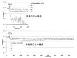
本発明の実施例に係る燃料電池スタックの効果を説明するために、図3は、通常のセル構成からなる従来のスタック発電部において、オープンエンドプレートから流入する水がセルに流入する様態を示しており、図4は、人為的に水を注入する場合、従来のスタック構造と本発明の実施例に係るスタック構造におけるセル電圧変動状況を示している。
図3に示すように、一般的なスタック構造において、スタックに水が流入する場合、水流入の開始から1〜2秒内に大部分の水は第1セルに流入し、相当量の水が第2セルに流入し、その後のセルには水がほぼ流入しないことが分かる。
したがって、凝縮水などの水がスタックに流入する場合、最外郭付近のセル(エンドセル部)が最もぜい弱であると予想される。
In order to explain the effect of the fuel cell stack according to the embodiment of the present invention, FIG. 3 illustrates a state in which water flowing from the open end plate flows into the cell in a conventional stack power generation unit having a normal cell configuration. FIG. 4 shows cell voltage fluctuations in the conventional stack structure and the stack structure according to the embodiment of the present invention when water is artificially injected.
As shown in FIG. 3, in a general stack structure, when water flows into the stack, most of the water flows into the first cell within 1 to 2 seconds from the start of the water inflow, and a considerable amount of water flows. It can be seen that water flows into the second cell and water hardly flows into the subsequent cells.
Therefore, when water such as condensed water flows into the stack, the cell near the outermost shell (end cell portion) is expected to be the weakest.
図4は、実際のスタックモジュールを用いてアノード入口に悪条件である30g/secの水を注入した場合の従来のスタック構造と本発明のスタック構造を示している。従来のスタック構造では、水の注入後、直ちに第1セルの性能(電圧)が急激に低下し、第2セルにも影響を及ぼすが、本発明のスタック構造では、数百秒が過ぎてもエンドセル付近の急激なセル性能(電圧)の低下はなかった。 これは流入する大部分の水が本発明に適用されたダミーセルに流入し、直ちに排出されるため、発電部セルへの水の流入が最小になることが分かる。
したがって、本発明に係る燃料電池スタックは、実際の車両において、スタックへの水の流入によるセル性能の不安定性、過量の水がセル内部に存在することによるMEA触媒劣化を最小にすることができる。
FIG. 4 shows a conventional stack structure and a stack structure according to the present invention when water of 30 g / sec, which is an adverse condition, is injected into the anode inlet using an actual stack module. In the conventional stack structure, the performance (voltage) of the first cell rapidly decreases immediately after injecting water, and the second cell is affected. However, in the stack structure of the present invention, even if several hundred seconds pass. There was no sudden drop in cell performance (voltage) near the end cell. This shows that most of the inflowing water flows into the dummy cell applied to the present invention and is immediately discharged, so that the inflow of water into the power generation unit cell is minimized.
Therefore, the fuel cell stack according to the present invention can minimize the instability of cell performance due to the inflow of water into the stack and the deterioration of the MEA catalyst due to the presence of excessive water in the cell in an actual vehicle. .
以上、本発明に関する好ましい実施形態を説明したが、本発明は前記実施形態に限定されず、本発明の属する技術範囲を逸脱しない範囲での全ての変更が含まれる。 As mentioned above, although preferred embodiment regarding this invention was described, this invention is not limited to the said embodiment, All the changes in the range which does not deviate from the technical scope to which this invention belongs are included.
1 燃料電池スタック
2 共用分配器
3 オープンエンドプレート
4 クローズエンドプレート
5 セル
7 スタック発電部
10 アノードプレート(AP)
20 カソードプレート(CP)
30 5レイヤーMEA
40 気体拡散層(GDL)
60 気体拡散層接合体(GG)
100 エンドアノードプレート(EAP)
120 水素マニホールド
140 冷却水マニホールド
160 空気マニホールド
180 ガスケット
200 エンドカソードプレート(ECP)
300 カソードダミーセル
320 アノードダミーセル
1
20 Cathode plate (CP)
30 5-layer MEA
40 Gas diffusion layer (GDL)
60 Gas diffusion layer assembly (GG)
100 End anode plate (EAP)
120
300 Cathode dummy cell 320 Anode dummy cell
Claims (7)
スタック発電部のエンドセルと前記両端のエンドプレート(EP)との間にはスタックの水排出のためのダミーセルとしてカソードダミーセル(CD)とアノードダミーセル(AD)がそれぞれ少なくとも一側に1つ以上積層されることを特徴とする水排出構造を有する燃料電池スタック。 A fuel cell stack in which a plurality of cells are stacked between end plates (EP) at both ends of the stack,
One or more cathode dummy cells (CD) and anode dummy cells (AD) are stacked on at least one side as dummy cells for discharging water from the stack between the end cells of the stack power generation unit and the end plates (EP) at both ends. A fuel cell stack having a water discharge structure.
Applications Claiming Priority (2)
| Application Number | Priority Date | Filing Date | Title |
|---|---|---|---|
| KR1020100114180A KR101251254B1 (en) | 2010-11-17 | 2010-11-17 | Fuel cell stack having water drain structure |
| KR10-2010-0114180 | 2010-11-17 |
Publications (2)
| Publication Number | Publication Date |
|---|---|
| JP2012109199A true JP2012109199A (en) | 2012-06-07 |
| JP5791940B2 JP5791940B2 (en) | 2015-10-07 |
Family
ID=46021424
Family Applications (1)
| Application Number | Title | Priority Date | Filing Date |
|---|---|---|---|
| JP2011086329A Active JP5791940B2 (en) | 2010-11-17 | 2011-04-08 | Fuel cell stack with water discharge structure |
Country Status (5)
| Country | Link |
|---|---|
| US (1) | US8785063B2 (en) |
| JP (1) | JP5791940B2 (en) |
| KR (1) | KR101251254B1 (en) |
| CN (1) | CN102468512B (en) |
| DE (1) | DE102011007378B4 (en) |
Cited By (3)
| Publication number | Priority date | Publication date | Assignee | Title |
|---|---|---|---|---|
| JP2016091944A (en) * | 2014-11-10 | 2016-05-23 | トヨタ自動車株式会社 | Fuel cell stack |
| JP2019160665A (en) * | 2018-03-15 | 2019-09-19 | 本田技研工業株式会社 | Fuel cell stack and dummy cell for fuel cell stack |
| JP2020194656A (en) * | 2019-05-27 | 2020-12-03 | トヨタ自動車株式会社 | Fuel cell and fuel cell manufacturing method |
Families Citing this family (14)
| Publication number | Priority date | Publication date | Assignee | Title |
|---|---|---|---|---|
| KR20150048407A (en) | 2013-10-28 | 2015-05-07 | 현대자동차주식회사 | Fuel cell stack having dummy cell |
| RU2677269C2 (en) | 2014-03-12 | 2019-01-16 | Серес Интеллекчуал Проперти Компани Лимитед | Fuel cell stack arrangement |
| KR102371046B1 (en) * | 2016-07-15 | 2022-03-07 | 현대자동차주식회사 | End cell heater for fuel cell |
| KR101896323B1 (en) | 2016-08-31 | 2018-09-07 | 현대자동차 주식회사 | Humidification device for fuel cell |
| JP6769300B2 (en) * | 2016-12-28 | 2020-10-14 | トヨタ自動車株式会社 | Fuel cell stack and dummy cell |
| DE102018201703A1 (en) | 2018-02-05 | 2019-08-08 | Audi Ag | Fuel cell system and motor vehicle with a fuel cell system |
| KR102659051B1 (en) * | 2018-08-20 | 2024-04-19 | 현대자동차주식회사 | Fuel cell |
| KR102676734B1 (en) | 2018-09-05 | 2024-06-19 | 현대자동차주식회사 | Fuel cell stack |
| JP6817357B2 (en) * | 2019-03-05 | 2021-01-20 | 本田技研工業株式会社 | Manufacturing method of fuel cell stack and dummy cell |
| KR102807283B1 (en) * | 2019-07-11 | 2025-05-14 | 주식회사 엘지화학 | Fuel cell stack and fuel cell comprising the same |
| KR102287321B1 (en) * | 2019-12-10 | 2021-08-09 | 현대자동차주식회사 | Fuel cell stack |
| DE102020007227A1 (en) | 2020-11-26 | 2022-06-02 | Cellcentric Gmbh & Co. Kg | Device for scavenging liquid |
| KR20230030425A (en) | 2021-08-25 | 2023-03-06 | 현대자동차주식회사 | Separator for fuel cell with insulating gasket and fuel cell stack having the same |
| DE102023206802A1 (en) * | 2023-07-18 | 2025-01-23 | Robert Bosch Gesellschaft mit beschränkter Haftung | insulation plate for a fuel cell stack |
Citations (4)
| Publication number | Priority date | Publication date | Assignee | Title |
|---|---|---|---|---|
| JP2003338305A (en) * | 2002-05-20 | 2003-11-28 | Toyota Motor Corp | Stack structure of fuel cell |
| JP2005317444A (en) * | 2004-04-30 | 2005-11-10 | Honda Motor Co Ltd | Fuel cell stack |
| JP2006344461A (en) * | 2005-06-08 | 2006-12-21 | Nissan Motor Co Ltd | Fuel cell stack |
| JP2010073448A (en) * | 2008-09-18 | 2010-04-02 | Honda Motor Co Ltd | Fuel cell stack |
Family Cites Families (8)
| Publication number | Priority date | Publication date | Assignee | Title |
|---|---|---|---|---|
| US6040072A (en) | 1997-11-19 | 2000-03-21 | Lynntech, Inc. | Apparatus and method for compressing a stack of electrochemical cells |
| WO2001071842A2 (en) | 2000-03-17 | 2001-09-27 | Allen Engineering Company, Inc. | Fuel cell stack assembly |
| US20050095492A1 (en) | 2001-05-15 | 2005-05-05 | Hydrogenics Corporation | Fuel cell stack |
| JP2003203669A (en) | 2001-12-28 | 2003-07-18 | Honda Motor Co Ltd | Fuel cell stack |
| JP4727972B2 (en) * | 2004-11-25 | 2011-07-20 | 本田技研工業株式会社 | Fuel cell stack |
| JP5079994B2 (en) | 2004-11-25 | 2012-11-21 | 本田技研工業株式会社 | Fuel cell stack |
| JP5060143B2 (en) | 2007-03-14 | 2012-10-31 | 本田技研工業株式会社 | Fuel cell stack |
| JP5144179B2 (en) | 2007-09-05 | 2013-02-13 | 本田技研工業株式会社 | Fuel cell stack |
-
2010
- 2010-11-17 KR KR1020100114180A patent/KR101251254B1/en active Active
-
2011
- 2011-04-05 US US13/080,406 patent/US8785063B2/en active Active
- 2011-04-08 JP JP2011086329A patent/JP5791940B2/en active Active
- 2011-04-14 DE DE102011007378.7A patent/DE102011007378B4/en active Active
- 2011-04-22 CN CN201110105124.2A patent/CN102468512B/en active Active
Patent Citations (4)
| Publication number | Priority date | Publication date | Assignee | Title |
|---|---|---|---|---|
| JP2003338305A (en) * | 2002-05-20 | 2003-11-28 | Toyota Motor Corp | Stack structure of fuel cell |
| JP2005317444A (en) * | 2004-04-30 | 2005-11-10 | Honda Motor Co Ltd | Fuel cell stack |
| JP2006344461A (en) * | 2005-06-08 | 2006-12-21 | Nissan Motor Co Ltd | Fuel cell stack |
| JP2010073448A (en) * | 2008-09-18 | 2010-04-02 | Honda Motor Co Ltd | Fuel cell stack |
Cited By (4)
| Publication number | Priority date | Publication date | Assignee | Title |
|---|---|---|---|---|
| JP2016091944A (en) * | 2014-11-10 | 2016-05-23 | トヨタ自動車株式会社 | Fuel cell stack |
| JP2019160665A (en) * | 2018-03-15 | 2019-09-19 | 本田技研工業株式会社 | Fuel cell stack and dummy cell for fuel cell stack |
| JP2020194656A (en) * | 2019-05-27 | 2020-12-03 | トヨタ自動車株式会社 | Fuel cell and fuel cell manufacturing method |
| JP7205381B2 (en) | 2019-05-27 | 2023-01-17 | トヨタ自動車株式会社 | Fuel cell manufacturing method |
Also Published As
| Publication number | Publication date |
|---|---|
| KR20120053103A (en) | 2012-05-25 |
| US20120121997A1 (en) | 2012-05-17 |
| US8785063B2 (en) | 2014-07-22 |
| CN102468512B (en) | 2016-04-13 |
| CN102468512A (en) | 2012-05-23 |
| JP5791940B2 (en) | 2015-10-07 |
| KR101251254B1 (en) | 2013-04-10 |
| DE102011007378A1 (en) | 2012-05-24 |
| DE102011007378B4 (en) | 2025-03-27 |
Similar Documents
| Publication | Publication Date | Title |
|---|---|---|
| JP5791940B2 (en) | Fuel cell stack with water discharge structure | |
| CN101677129B (en) | Fuel cell stack | |
| CA2472138C (en) | End structure of a fuel cell stack | |
| EP1517392B1 (en) | Solid high polymer type cell assembly | |
| WO2007083838A1 (en) | Fuel cell | |
| KR20150048407A (en) | Fuel cell stack having dummy cell | |
| CN110336064B (en) | Fuel cell stack | |
| JP4939100B2 (en) | Fuel cell stack | |
| JP5372668B2 (en) | Fuel cell stack | |
| JP5167058B2 (en) | Aging method for polymer electrolyte fuel cell | |
| JP2004134130A (en) | Fuel cell stack | |
| JP2009526345A (en) | Fuel cell stack | |
| KR20200000913A (en) | The separator for fuel cell | |
| JP4739880B2 (en) | Polymer electrolyte fuel cell | |
| KR102775074B1 (en) | Fuel cell stack and Fuel cell system including the same | |
| JP2008130350A (en) | Fuel cell | |
| JP2001351666A (en) | Phosphoric acid type fuel cell system and its stopping method | |
| JP2006079880A (en) | Fuel cell system | |
| JP2013114899A (en) | Fuel cell stack | |
| JP2010282904A (en) | Fuel cell system | |
| US20080090126A1 (en) | Preservation Method Of Polymer Electrolyte Membrane Electrode Assembly Technical Field | |
| JP2004014299A (en) | Fuel cell | |
| JP2007115620A (en) | Separator for polymer electrolyte fuel cell and polymer electrolyte fuel cell | |
| JP2007018800A (en) | Fuel cell stack | |
| JP2004265632A (en) | Polymer electrolyte fuel cell |
Legal Events
| Date | Code | Title | Description |
|---|---|---|---|
| A621 | Written request for application examination |
Free format text: JAPANESE INTERMEDIATE CODE: A621 Effective date: 20140225 |
|
| A131 | Notification of reasons for refusal |
Free format text: JAPANESE INTERMEDIATE CODE: A131 Effective date: 20150127 |
|
| A977 | Report on retrieval |
Free format text: JAPANESE INTERMEDIATE CODE: A971007 Effective date: 20150128 |
|
| A521 | Request for written amendment filed |
Free format text: JAPANESE INTERMEDIATE CODE: A523 Effective date: 20150422 |
|
| TRDD | Decision of grant or rejection written | ||
| A01 | Written decision to grant a patent or to grant a registration (utility model) |
Free format text: JAPANESE INTERMEDIATE CODE: A01 Effective date: 20150804 |
|
| A61 | First payment of annual fees (during grant procedure) |
Free format text: JAPANESE INTERMEDIATE CODE: A61 Effective date: 20150805 |
|
| R150 | Certificate of patent or registration of utility model |
Ref document number: 5791940 Country of ref document: JP Free format text: JAPANESE INTERMEDIATE CODE: R150 |
|
| R250 | Receipt of annual fees |
Free format text: JAPANESE INTERMEDIATE CODE: R250 |
|
| R250 | Receipt of annual fees |
Free format text: JAPANESE INTERMEDIATE CODE: R250 |
|
| R250 | Receipt of annual fees |
Free format text: JAPANESE INTERMEDIATE CODE: R250 |
|
| R250 | Receipt of annual fees |
Free format text: JAPANESE INTERMEDIATE CODE: R250 |
|
| R250 | Receipt of annual fees |
Free format text: JAPANESE INTERMEDIATE CODE: R250 |
|
| R250 | Receipt of annual fees |
Free format text: JAPANESE INTERMEDIATE CODE: R250 |
|
| R250 | Receipt of annual fees |
Free format text: JAPANESE INTERMEDIATE CODE: R250 |
|
| R157 | Certificate of patent or utility model (correction) |
Free format text: JAPANESE INTERMEDIATE CODE: R157 |
|
| R250 | Receipt of annual fees |
Free format text: JAPANESE INTERMEDIATE CODE: R250 |
|
| S533 | Written request for registration of change of name |
Free format text: JAPANESE INTERMEDIATE CODE: R313533 |
|
| R350 | Written notification of registration of transfer |
Free format text: JAPANESE INTERMEDIATE CODE: R350 |
|
| R157 | Certificate of patent or utility model (correction) |
Free format text: JAPANESE INTERMEDIATE CODE: R157 |