JP2012109382A - 回路基板とリード線との接続構造及び方法 - Google Patents
回路基板とリード線との接続構造及び方法 Download PDFInfo
- Publication number
- JP2012109382A JP2012109382A JP2010256755A JP2010256755A JP2012109382A JP 2012109382 A JP2012109382 A JP 2012109382A JP 2010256755 A JP2010256755 A JP 2010256755A JP 2010256755 A JP2010256755 A JP 2010256755A JP 2012109382 A JP2012109382 A JP 2012109382A
- Authority
- JP
- Japan
- Prior art keywords
- lead wire
- circuit board
- hole
- insertion pin
- lead wires
- Prior art date
- Legal status (The legal status is an assumption and is not a legal conclusion. Google has not performed a legal analysis and makes no representation as to the accuracy of the status listed.)
- Granted
Links
- WABPQHHGFIMREM-UHFFFAOYSA-N lead(0) Chemical compound [Pb] WABPQHHGFIMREM-UHFFFAOYSA-N 0.000 title claims abstract description 70
- 238000000034 method Methods 0.000 title claims description 16
- 238000003780 insertion Methods 0.000 claims abstract description 35
- 230000037431 insertion Effects 0.000 claims abstract description 35
- 239000004020 conductor Substances 0.000 claims abstract description 32
- 238000005452 bending Methods 0.000 claims abstract description 8
- 239000011347 resin Substances 0.000 claims description 7
- 229920005989 resin Polymers 0.000 claims description 7
- 238000005304 joining Methods 0.000 claims description 4
- 238000004519 manufacturing process Methods 0.000 abstract description 5
- 238000003466 welding Methods 0.000 description 12
- 238000000465 moulding Methods 0.000 description 6
- 239000012212 insulator Substances 0.000 description 4
- 229910000679 solder Inorganic materials 0.000 description 4
- 238000001746 injection moulding Methods 0.000 description 3
- 238000002844 melting Methods 0.000 description 3
- 230000008018 melting Effects 0.000 description 3
- 238000005476 soldering Methods 0.000 description 3
- 239000004593 Epoxy Substances 0.000 description 2
- 238000012790 confirmation Methods 0.000 description 2
- 238000010438 heat treatment Methods 0.000 description 2
- 238000012986 modification Methods 0.000 description 2
- 230000004048 modification Effects 0.000 description 2
- 238000004382 potting Methods 0.000 description 2
- RYGMFSIKBFXOCR-UHFFFAOYSA-N Copper Chemical compound [Cu] RYGMFSIKBFXOCR-UHFFFAOYSA-N 0.000 description 1
- 230000002730 additional effect Effects 0.000 description 1
- 238000007796 conventional method Methods 0.000 description 1
- 229910052802 copper Inorganic materials 0.000 description 1
- 239000010949 copper Substances 0.000 description 1
- 238000010586 diagram Methods 0.000 description 1
- 239000000463 material Substances 0.000 description 1
- 239000000203 mixture Substances 0.000 description 1
Images


Landscapes
- Multi-Conductor Connections (AREA)
- Coupling Device And Connection With Printed Circuit (AREA)
- Structures For Mounting Electric Components On Printed Circuit Boards (AREA)
Abstract
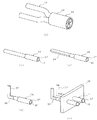
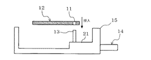
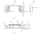
【解決手段】複数のスルーホール11が形成された回路基板12と、複数のスルーホール11のいずれかに挿入されて接続されるスルーホール挿入ピン部13を有する複数のリード線14と、複数のリード線14のスルーホール挿入ピン部13のそれぞれが対応するスルーホール11に挿入されるように、複数のリード線14を位置決め固定するリード線固定部材15と、を備え、スルーホール挿入ピン部13は、リード線14の導体露出部20に曲げ加工を施して形成されるものである。
【選択図】図1
Description
11 スルーホール
12 回路基板
13 スルーホール挿入ピン部
14 リード線
15 リード線固定部材
16 導体
17 絶縁体
18 シース
19 ケーブル
20 導体露出部
21 台座部
Claims (4)
- 複数のスルーホールが形成された回路基板と、
前記複数のスルーホールのいずれかに挿入されて接続されるスルーホール挿入ピン部を有する複数のリード線と、
前記複数のリード線の前記スルーホール挿入ピン部のそれぞれが対応する前記スルーホールに挿入されるように、前記複数のリード線を位置決め固定するリード線固定部材と、 を備え、
前記スルーホール挿入ピン部は、前記リード線の導体露出部に曲げ加工を施して形成されることを特徴とする回路基板とリード線との接続構造。 - 前記リード線の導体露出部は、前記リード線の露出された導体を素線固めして形成される請求項1に記載の回路基板とリード線との接続構造。
- 前記リード線固定部材は、前記スルーホールに挿入される前記スルーホール挿入ピン部の端部を除く前記リード線の端部を覆うように形成されると共に、前記回路基板を載置するための台座部を有する請求項1又は2に記載の回路基板とリード線との接続構造。
- 回路基板に複数のスルーホールを形成し、
複数のリード線のそれぞれを段剥きして導体を露出させ、
前記複数のリード線の露出された前記導体を素線固めして導体露出部を形成し、
前記複数のリード線の前記導体露出部のそれぞれに曲げ加工を施して、前記複数のスルーホールのいずれかに挿入するためのスルーホール挿入ピン部を形成し、
前記複数のリード線の前記スルーホール挿入ピン部のそれぞれが対応する前記スルーホールに挿入されるように、前記複数のリード線を位置決め固定し、
前記複数のリード線の前記スルーホール挿入ピン部のそれぞれを対応する前記スルーホールに挿入すると共に接合して、前記回路基板と前記リード線を接続し、
前記リード線と接続した前記回路基板を樹脂でポッティグすることを特徴とする回路基板とリード線との接続方法。
Priority Applications (1)
| Application Number | Priority Date | Filing Date | Title |
|---|---|---|---|
| JP2010256755A JP5556609B2 (ja) | 2010-11-17 | 2010-11-17 | 回路基板とリード線との接続構造 |
Applications Claiming Priority (1)
| Application Number | Priority Date | Filing Date | Title |
|---|---|---|---|
| JP2010256755A JP5556609B2 (ja) | 2010-11-17 | 2010-11-17 | 回路基板とリード線との接続構造 |
Publications (2)
| Publication Number | Publication Date |
|---|---|
| JP2012109382A true JP2012109382A (ja) | 2012-06-07 |
| JP5556609B2 JP5556609B2 (ja) | 2014-07-23 |
Family
ID=46494693
Family Applications (1)
| Application Number | Title | Priority Date | Filing Date |
|---|---|---|---|
| JP2010256755A Expired - Fee Related JP5556609B2 (ja) | 2010-11-17 | 2010-11-17 | 回路基板とリード線との接続構造 |
Country Status (1)
| Country | Link |
|---|---|
| JP (1) | JP5556609B2 (ja) |
Cited By (3)
| Publication number | Priority date | Publication date | Assignee | Title |
|---|---|---|---|---|
| US20170222387A1 (en) * | 2016-01-29 | 2017-08-03 | The Boeing Company | Vibrating pallet system for automated wire insertion |
| CN109510361A (zh) * | 2018-12-27 | 2019-03-22 | 长沙理工大学 | 一种三相异步发电机定子引出线连接结构 |
| JP2024104928A (ja) * | 2023-01-25 | 2024-08-06 | 株式会社プロテリアル | 構造体の製造方法 |
Citations (5)
| Publication number | Priority date | Publication date | Assignee | Title |
|---|---|---|---|---|
| JPS5691492A (en) * | 1979-12-26 | 1981-07-24 | Hitachi Ltd | Method of mounting lead wire |
| JPS58141512U (ja) * | 1982-03-19 | 1983-09-24 | 渡邊 和彦 | 配線材集合体 |
| JPH0292971U (ja) * | 1989-01-12 | 1990-07-24 | ||
| JPH0496886U (ja) * | 1991-01-31 | 1992-08-21 | ||
| JPH1012289A (ja) * | 1996-06-19 | 1998-01-16 | Mitsubishi Electric Corp | 電気的接続端子及びその製造方法 |
-
2010
- 2010-11-17 JP JP2010256755A patent/JP5556609B2/ja not_active Expired - Fee Related
Patent Citations (5)
| Publication number | Priority date | Publication date | Assignee | Title |
|---|---|---|---|---|
| JPS5691492A (en) * | 1979-12-26 | 1981-07-24 | Hitachi Ltd | Method of mounting lead wire |
| JPS58141512U (ja) * | 1982-03-19 | 1983-09-24 | 渡邊 和彦 | 配線材集合体 |
| JPH0292971U (ja) * | 1989-01-12 | 1990-07-24 | ||
| JPH0496886U (ja) * | 1991-01-31 | 1992-08-21 | ||
| JPH1012289A (ja) * | 1996-06-19 | 1998-01-16 | Mitsubishi Electric Corp | 電気的接続端子及びその製造方法 |
Cited By (6)
| Publication number | Priority date | Publication date | Assignee | Title |
|---|---|---|---|---|
| US20170222387A1 (en) * | 2016-01-29 | 2017-08-03 | The Boeing Company | Vibrating pallet system for automated wire insertion |
| US10109974B2 (en) * | 2016-01-29 | 2018-10-23 | The Boeing Company | Vibrating pallet system for automated wire insertion |
| US11271353B2 (en) | 2016-01-29 | 2022-03-08 | The Boeing Company | Vibrating pallet system for automated wire insertion |
| CN109510361A (zh) * | 2018-12-27 | 2019-03-22 | 长沙理工大学 | 一种三相异步发电机定子引出线连接结构 |
| CN109510361B (zh) * | 2018-12-27 | 2024-02-02 | 长沙理工大学 | 一种三相异步发电机定子引出线连接结构 |
| JP2024104928A (ja) * | 2023-01-25 | 2024-08-06 | 株式会社プロテリアル | 構造体の製造方法 |
Also Published As
| Publication number | Publication date |
|---|---|
| JP5556609B2 (ja) | 2014-07-23 |
Similar Documents
| Publication | Publication Date | Title |
|---|---|---|
| US8900007B2 (en) | Cable connector and cable assembly, and method of manufacturing cable assembly | |
| US20120318576A1 (en) | Connecting structure and connecting method for electric cables | |
| CN106571531B (zh) | 一种天线装置以及该天线装置的制造方法 | |
| JP4897964B2 (ja) | 電流検出装置 | |
| CN105393648A (zh) | 具有侧面进入的端接焊盘的印制电路板 | |
| CN105390905B (zh) | 覆皮电线的接合方法 | |
| JP5556609B2 (ja) | 回路基板とリード線との接続構造 | |
| CN114938695B (zh) | 具有一体式固定结构的用于定子绕组的电路板 | |
| JP6941731B2 (ja) | 電気デバイス用の撚り線コネクタ及び撚り線コネクタの製造方法 | |
| JP6042635B2 (ja) | 電線の端末処理方法 | |
| JP6381439B2 (ja) | ケーブル接続構造 | |
| JP6674847B2 (ja) | モータのステータ組立方法およびモータのステータ構造 | |
| US20040100157A1 (en) | Electric machine end turn connectors | |
| JP2011070949A (ja) | 電線接続構造 | |
| TWM610104U (zh) | 纜線組件 | |
| US7743496B2 (en) | Cable termination methods | |
| JP5633725B2 (ja) | 回路構成体及び電気接続箱 | |
| JP2010288402A (ja) | 細径同軸ケーブルアレイ及びその製造方法 | |
| JP2017191863A (ja) | 半導体装置 | |
| JP2002112490A (ja) | 電動機の口出線取り付け構造 | |
| JP3978318B2 (ja) | ワイヤハーネスの製造方法 | |
| JP2006244895A (ja) | 同軸ケーブル、及び、該同軸ケーブルと配線基板との接続構造 | |
| JP2021087340A (ja) | モータ | |
| JP5573543B2 (ja) | 回路構成体及び電気接続箱 | |
| JP2008198844A (ja) | 電装品ユニットの製造方法 |
Legal Events
| Date | Code | Title | Description |
|---|---|---|---|
| A621 | Written request for application examination |
Free format text: JAPANESE INTERMEDIATE CODE: A621 Effective date: 20130125 |
|
| A977 | Report on retrieval |
Free format text: JAPANESE INTERMEDIATE CODE: A971007 Effective date: 20131015 |
|
| A131 | Notification of reasons for refusal |
Free format text: JAPANESE INTERMEDIATE CODE: A131 Effective date: 20131022 |
|
| A711 | Notification of change in applicant |
Free format text: JAPANESE INTERMEDIATE CODE: A712 Effective date: 20131105 |
|
| A521 | Written amendment |
Free format text: JAPANESE INTERMEDIATE CODE: A523 Effective date: 20131220 |
|
| TRDD | Decision of grant or rejection written | ||
| A01 | Written decision to grant a patent or to grant a registration (utility model) |
Free format text: JAPANESE INTERMEDIATE CODE: A01 Effective date: 20140507 |
|
| A61 | First payment of annual fees (during grant procedure) |
Free format text: JAPANESE INTERMEDIATE CODE: A61 Effective date: 20140520 |
|
| R150 | Certificate of patent or registration of utility model |
Ref document number: 5556609 Country of ref document: JP Free format text: JAPANESE INTERMEDIATE CODE: R150 |
|
| LAPS | Cancellation because of no payment of annual fees |