JP2012109663A - Bone conduction transmitting/receiving apparatus - Google Patents
Bone conduction transmitting/receiving apparatus Download PDFInfo
- Publication number
- JP2012109663A JP2012109663A JP2010254890A JP2010254890A JP2012109663A JP 2012109663 A JP2012109663 A JP 2012109663A JP 2010254890 A JP2010254890 A JP 2010254890A JP 2010254890 A JP2010254890 A JP 2010254890A JP 2012109663 A JP2012109663 A JP 2012109663A
- Authority
- JP
- Japan
- Prior art keywords
- speaker
- bone conduction
- pressure
- audio
- audio signal
- Prior art date
- Legal status (The legal status is an assumption and is not a legal conclusion. Google has not performed a legal analysis and makes no representation as to the accuracy of the status listed.)
- Withdrawn
Links
Images





Landscapes
- Details Of Audible-Bandwidth Transducers (AREA)
- Circuit For Audible Band Transducer (AREA)
Abstract
【課題】音声用スピーカと骨伝導スピーカを備えて、音声の出力先を自然な形で切り替えることができる骨伝導受話装置を提供する。
【解決手段】骨伝導により音声信号を伝える骨伝導スピーカ13と、空気伝導により音声信号を伝える音声用スピーカ12と、圧力を検出する感圧センサ14と、スピーカ制御部15とを備え、前記スピーカ制御部は、前記感圧センサが検出した圧力にしたがって、前記骨伝導スピーカに音声信号を供給するか、前記音声用スピーカに音声信号を供給するかを決定する。
【選択図】図2The present invention provides a bone conduction receiver that includes a voice speaker and a bone conduction speaker, and can switch a voice output destination in a natural manner.
The speaker includes a bone conduction speaker for transmitting an audio signal by bone conduction, an audio speaker for transmitting an audio signal by air conduction, a pressure-sensitive sensor for detecting pressure, and a speaker control unit. The control unit determines whether to supply an audio signal to the bone conduction speaker or an audio signal to the audio speaker according to the pressure detected by the pressure sensor.
[Selection] Figure 2
Description
本発明は、骨伝導受話装置に関する。 The present invention relates to a bone conduction receiver.
携帯電話や固定電話の受話装置、あるいはオーディオプレーヤ等では、一般的な音声用スピーカに加え、骨伝導スピーカが用いられてきている。一般的な音声用スピーカでは、
音声用スピーカが発生した音波が外耳道を経由して鼓膜を振動させ、耳小骨を経由して音を内耳に伝える。これに対して骨伝導スピーカでは、振動子が骨を振動させることで、振動を内耳に伝える。内耳に振動が伝えられると、蝸牛の内部のリンパ液が振動して電気信号に置き換えられて聴覚神経に送られ、それを脳が感知して音として認識する。
Bone conduction speakers have been used in addition to general audio speakers in portable telephone and landline telephone receivers, audio players, and the like. For general audio speakers,
Sound waves generated by the sound speaker vibrate the eardrum via the external auditory canal and transmit the sound to the inner ear via the ear ossicles. On the other hand, in the bone conduction speaker, the vibrator transmits the vibration to the inner ear by vibrating the bone. When vibration is transmitted to the inner ear, the lymph fluid inside the cochlea is vibrated and replaced with an electrical signal that is sent to the auditory nerve, which the brain senses and recognizes as sound.
骨伝導スピーカでは、頭蓋骨などの固い骨に振動子を接触させるものが主流であり、一般にはこめかみ付近に振動を与えるものが多い。骨伝導スピーカでは、軟骨を振動させて音を内耳に伝える軟骨伝導を利用したものもある。このような軟骨伝導スピーカでは、振動子を耳珠に押し当てるものが一般的である。 Bone-conducting speakers are mainly used to bring a vibrator into contact with a hard bone such as the skull, and generally give vibration near the temple. Some bone conduction speakers utilize cartilage conduction that vibrates the cartilage and transmits sound to the inner ear. In such a cartilage conduction speaker, generally, a vibrator is pressed against the tragus.
一般に、このような骨伝導スピーカは、音波を発生しないため原理的に音漏れが発生せず、音波とは別の経路で音声信号が伝えられるため周囲が騒がしい環境下でも明瞭に聞こえやすいなどの利点がある一方で、振動子を耳珠に押し付ける力が弱いと振動が蝸牛まで良好に伝わらないので振動子を耳珠にしっかりと押し付ける必要があり、また、原理的に低音域の出力レベルが低いといった問題もある。 In general, such a bone conduction speaker does not generate sound waves and thus does not leak sound in principle, and since sound signals are transmitted through a route different from sound waves, it is easy to hear clearly even in a noisy environment. On the other hand, if the force pressing the vibrator against the tragus is weak, the vibration will not be transmitted well to the cochlea, so it is necessary to press the vibrator firmly against the tragus, and in principle the output level in the low range is There is also a problem such as low.
特許文献1には、骨伝導スピーカと音声用スピーカから同時に音声出力し、音声用スピーカにおいて特定の周波数以上の高域で出力を抑制することにより、音声用スピーカからの音漏れを防止しつつ、骨伝導スピーカにおける低音域の不足を音声用スピーカによって補うことで、自然な音声を聴取することができるようにした受話装置が開示されている。
In
特許文献2には、複数のスピーカを備えた携帯電話において、出力する音声が通話によるものか通話以外によるものかに応じて、用いるスピーカを選択して音声出力する技術が開示されている。
特許文献1に記載の受話装置では、常に骨伝導スピーカと音声用スピーカの両方から音声出力を行い、音声の出力先を骨伝導スピーカ、あるいは音声用スピーカかに切り替えることができないといった問題があった。
The receiving device described in
特許文献2の技術を適用して音声の出力先を骨伝導スピーカと音声用スピーカとで切り替えることも考えられるが、特許文献2に記載の携帯端末装置では、音声出力が通話によるものか通話以外によるものかに応じて出力先は自動的に切り替わってしまうため、周囲の状況に応じて使用者の意図に従うように音声の出力先を自然な形で切り替えることはできなかった。
Although it is conceivable to switch the audio output destination between the bone conduction speaker and the audio speaker by applying the technology of
本発明は、このような実情に鑑みてなされたものであり、音声用スピーカと骨伝導スピーカを備えて、音声の出力先を自然な形で切り替えることができる骨伝導受話装置を提供する。 The present invention has been made in view of the above circumstances, and provides a bone conduction receiver that includes a voice speaker and a bone conduction speaker and can switch a voice output destination in a natural manner.
本発明の骨伝導受話装置は、骨伝導スピーカを耳珠に押し付ける圧力に応じて、音声の出力先を制御して骨伝導スピーカと音声用スピーカとで切り替えることを特徴とする。 The bone conduction receiving device according to the present invention is characterized by switching between a bone conduction speaker and a voice speaker by controlling a sound output destination according to a pressure pressing the bone conduction speaker against the tragus.
本発明の骨伝導受話装置は、骨伝導により音声信号を伝える骨伝導スピーカと、空気伝導により音声信号を伝える音声用スピーカと、圧力を検出する感圧センサと、スピーカ制御部とを備え、前記スピーカ制御部は、前記感圧センサが検出した圧力にしたがって、前記骨伝導スピーカへの音声信号の供給と、前記音声用スピーカへの音声信号の供給を制御することを特徴とする。 The bone conduction receiver of the present invention includes a bone conduction speaker that transmits an audio signal by bone conduction, an audio speaker that transmits an audio signal by air conduction, a pressure-sensitive sensor that detects pressure, and a speaker control unit, The speaker control unit controls supply of an audio signal to the bone conduction speaker and supply of an audio signal to the audio speaker according to the pressure detected by the pressure sensor.
前記スピーカ制御部は、前記感圧センサが検出した圧力にしたがって、前記骨伝導スピーカに音声信号を供給するか、前記音声用スピーカに音声信号を供給するかを決定するようにしてもよい。 The speaker control unit may determine whether to supply an audio signal to the bone conduction speaker or an audio signal to the audio speaker according to the pressure detected by the pressure sensor.
前記スピーカ制御部は、前記感圧センサが検出した圧力が第1の所定の値以上の場合、前記骨伝導スピーカに音声信号を供給し、前記感圧センサが検出した圧力が第1の所定の値未満の場合、前記音声用スピーカに音声信号を供給するようにしてもよい。 The speaker control unit supplies an audio signal to the bone conduction speaker when the pressure detected by the pressure sensor is equal to or greater than a first predetermined value, and the pressure detected by the pressure sensor is a first predetermined value. If the value is less than the value, an audio signal may be supplied to the audio speaker.
前記スピーカ制御部は、前記感圧センサが検出した圧力の値が第2の所定の値以上であって且つ第3の所定の値以下の範囲内である場合は前記骨伝導スピーカと前記音声用スピーカの両方に音声信号を供給し、前記感圧センサが検出した圧力の値が前記第3の所定の値より大きい値の場合は前記骨伝導スピーカに音声信号を供給し、前記感圧センサが検出した圧力の値が前記第2の所定の値未満の値の場合は前記音声用スピーカに音声信号を供給するようにしてもよい。 When the pressure value detected by the pressure sensor is equal to or greater than a second predetermined value and within a range equal to or smaller than a third predetermined value, the speaker control unit An audio signal is supplied to both speakers, and if the pressure value detected by the pressure sensor is greater than the third predetermined value, an audio signal is supplied to the bone conduction speaker, and the pressure sensor If the detected pressure value is less than the second predetermined value, an audio signal may be supplied to the audio speaker.
前記スピーカ制御部は、前記感圧センサが検出した圧力の値が大きくなるにつれ、前記音声用スピーカに供給する音声信号を小さくし、前記骨伝導スピーカに供給する音声信号を大きくするようにしてもよい。 The speaker control unit may decrease the audio signal supplied to the audio speaker and increase the audio signal supplied to the bone conduction speaker as the pressure value detected by the pressure sensor increases. Good.
前記スピーカ制御部は、前記感圧センサが検出した圧力が一定時間以上第1の所定の値以上または未満であった場合に、音声信号の供給先を切り替えるようにしてもよい。 The speaker control unit may switch the supply destination of the audio signal when the pressure detected by the pressure-sensitive sensor is greater than or less than a first predetermined value for a certain period of time.
前記感圧センサは筐体短辺方向または長辺方向の端部の前記骨伝導スピーカの近傍に配置してもよい。 The pressure-sensitive sensor may be arranged in the vicinity of the bone conduction speaker at the end in the short side direction or the long side direction of the housing.
本体側筐体と蓋側筐体とからなるクラムシェル型の形状を有し、前記感圧センサは、前記本体側筐体と前記蓋側筐体とを連結する軸部分に配置してもよい。 It has a clamshell type shape composed of a main body side case and a lid side case, and the pressure sensitive sensor may be disposed on a shaft portion that connects the main body side case and the lid side case. .
前記骨伝導スピーカは前記音声用スピーカを挟んで筐体角部に配置してもよい。
前記スピーカ制御部は、音声信号の供給中、前記感圧センサが検出した圧力が変化しても音声信号の供給先を変更しないようにしてもよい。
The bone conduction speaker may be disposed at a corner of the casing with the audio speaker interposed therebetween.
The speaker control unit may not change the supply destination of the audio signal even if the pressure detected by the pressure sensor changes during the supply of the audio signal.
前記スピーカ制御部は、音声信号の供給中、前記感圧センサが検出した圧力の変化に応じて音声信号の供給先を切り替えるようにしてもよい。 The speaker control unit may switch a supply destination of the audio signal according to a change in pressure detected by the pressure sensor during supply of the audio signal.
前記スピーカ制御部は、音声信号の供給先が前記骨伝導スピーカ、あるいは前記音声用スピーカのどちらか一方に固定するモードに設定されている場合、音声信号の供給中、前記感圧センサが検出した圧力が変化しても音声信号の供給先を変更しないようにしてもよい。 The speaker control unit detects the pressure sensor while supplying the audio signal when the audio signal is supplied to the bone conduction speaker or the audio speaker. The supply destination of the audio signal may not be changed even if the pressure changes.
音声信号の供給先を前記音声用スピーカから前記骨伝導スピーカに切り替える圧力値を第4の所定の値とし、音声信号の供給先を前記骨伝導スピーカから前記音声用スピーカに切り替える圧力値を第5の所定の値とし、前記第5の所定の値のほうが前記第4の所定の値よりも小さくなるようにしてもよい。 The pressure value for switching the audio signal supply destination from the audio speaker to the bone conduction speaker is a fourth predetermined value, and the pressure value for switching the audio signal supply destination from the bone conduction speaker to the audio speaker is fifth. The fifth predetermined value may be smaller than the fourth predetermined value.
本発明によれば、音声用スピーカと骨伝導スピーカを備えて、音声の出力先を自然な形で切り替えることができる。 ADVANTAGE OF THE INVENTION According to this invention, the audio | voice speaker and the bone conduction speaker are provided, and the output destination of an audio | voice can be switched in a natural form.
以下、図面を参照して本発明の実施の形態について説明する。
図1は、本発明を携帯電話に適用した構成の一例を示すブロック図である。本発明による携帯電話は、受話部1と、音声用マイク2と、マイク制御部3と、制御部4と、操作部5と、通信制御部6と、アンテナ7と、表示制御部8と、表示部9と、電源管理部10と、バッテリ11とを備える。
Embodiments of the present invention will be described below with reference to the drawings.
FIG. 1 is a block diagram showing an example of a configuration in which the present invention is applied to a mobile phone. The mobile phone according to the present invention includes a
受話部1は、制御部4から供給される音声データを音に変換する。これについては後に詳しく説明する。音声用マイク2は、使用者の音声を電気信号に変換する。マイク制御部3は、音声用マイク2が変換した電気信号に増幅などの処理をした後、制御部4に供給する。制御部4は、携帯電話の各部の動作を制御する。操作部5は、使用者の操作を受け付ける部分であり、電話番号の入力や電子メールの文字入力等を行うテンキーや、方向キー、各種機能を起動させる機能キー等を含む。通信制御部6は、アンテナ7を介して基地局を経て他の携帯電話や固定電話と通信する。表示制御部8は、液晶ディスプレイ等からなる表示部9に操作インタフェースや入力した電話番号、着信情報、電子メール等を表示する。電源管理部10は、バッテリ11からの電力を各部に分配したり、バッテリ11の充電の制御などを行う。
The
本発明の携帯電話は、受話部1の構成以外は、従来の携帯電話と同様の構成であってもよい。
The mobile phone of the present invention may have the same configuration as that of a conventional mobile phone except for the configuration of the
図2は、図1の受話部1の構成の一例を示すブロック図である。受話部1は、音声用スピーカ12と、骨伝導スピーカ13と、接触(感圧)センサ14と、スピーカ制御部15とを備える。
FIG. 2 is a block diagram showing an example of the configuration of the
音声用スピーカ12は、例えば電磁型スピーカであり、電気信号を音波に変換する。音声用スピーカ12が放出する音波は、外耳道を経由して鼓膜を振動させ、耳小骨を経由して音を内耳に伝える。内耳に音が伝えられると、蝸牛の内部のリンパ液が振動して電気信号に置き換えられて聴覚神経に送られ、それを脳が感知して音として認識する。
The
骨伝導スピーカ13は、軟骨伝導を利用したものであり、例えば、電磁型または圧電型のものである。骨伝導スピーカ13は、電気信号を振動に変換する。骨伝導スピーカ13が耳珠に押し当てられると、骨伝導スピーカ13が発生した振動は耳珠や他の軟骨部を経由して内耳に伝えられる。内耳に振動が伝えられると、蝸牛の内部のリンパ液が振動して電気信号に置き換えられて聴覚神経に送られ、それを脳が感知して音として認識する。
The
接触(感圧)センサ14は、受話部1がどの程度耳に押し付けられているか、すなわち、骨伝導スピーカ13と耳珠がどの程度の圧力で接しているのかを検出する。接触(感圧)センサ14は、このような圧力が検出できるものであるならば、どのような形式のものであってもかまわない。
The contact (pressure-sensitive)
スピーカ制御部15は、接触(感圧)センサ14が検出した圧力に応じて、音声の出力先を制御して音声用スピーカ12と骨伝導スピーカ13とで切り替える。
The
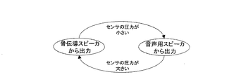
図3および図4は、スピーカ制御部15による音声の出力先の切り替えを説明する図である。接触(感圧)センサ14が検出した圧力が所定の値未満である場合は、骨伝導スピーカ13が耳珠に強く押し付けられていないと判断し、軟骨伝導の作用が期待できないため、音声用スピーカ12が音声の出力先となるように切り替える。
FIG. 3 and FIG. 4 are diagrams for explaining switching of the audio output destination by the
接触(感圧)センサ14が検出した圧力が所定の値以上である場合は、骨伝導スピーカ13が耳珠に強く押し付けられていると判断し、軟骨伝導の作用が期待できるため、骨伝導スピーカ13が音声の出力先となるように切り替える。耳珠がある程度強く押されると、耳珠が気道を塞ぐため、外界音が遮断される。したがって、周囲が騒がしい環境下では、骨伝導スピーカ13が耳珠に当たるようにして受話部を強く押し付ければ、音声の出力先が骨伝導スピーカに切り替わるとともに、耳珠が気道を塞ぎ、外界音が遮断され、軟骨伝導による音声のみが明瞭に聞こえるという効果が得られる。
When the pressure detected by the contact (pressure-sensitive)
一般に、骨伝導スピーカを耳珠に押し付ける押圧は100g〜300g程度が適切であるため、音声用スピーカ12と骨伝導スピーカ13とを切り替える圧力の値としては100g程度が適切であろう。
Generally, the pressure for pressing the bone conduction speaker against the tragus is appropriately about 100 g to 300 g, so that the pressure value for switching between the
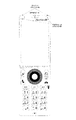
図5は、携帯電話における骨伝導スピーカ、音声用スピーカおよび接触(感圧)センサの適切な位置関係の一例を説明するための図である。この例では、本体側筐体に操作部と音声用マイクが配置され、蓋側筐体に音声出力部と表示部が配置される一般的なクラムシェル型の携帯電話を示す。音声用スピーカは、蓋側筐体における表示部の上方ほぼ中央に配置される。この配置は、一般的なクラムシェル型の携帯電話のスピーカの配置と同様である。骨伝導スピーカは、耳珠に当てやすいように、蓋側筐体の角に少なくとも1個設けることが望ましい。この際、音声用スピーカと骨伝導スピーカとの間隔を、耳珠から耳穴までの平均的な距離とすることが望ましい。このようにすれば、骨伝導スピーカを耳珠に当てたとき、音声用スピーカが耳穴の位置にくることになり、音声用スピーカおよび骨伝導スピーカは共に最適な位置になる。図6に、このような音声用スピーカおよび骨伝導スピーカと耳との位置関係を示す。 FIG. 5 is a diagram for explaining an example of an appropriate positional relationship among a bone conduction speaker, a voice speaker, and a contact (pressure-sensitive) sensor in a mobile phone. In this example, a general clamshell type mobile phone in which an operation unit and a voice microphone are arranged in a main body side housing and a voice output unit and a display unit are arranged in a lid side housing is shown. The audio speaker is disposed approximately at the center above the display unit in the lid-side housing. This arrangement is the same as that of a speaker of a general clamshell type mobile phone. It is desirable to provide at least one bone conduction speaker at the corner of the lid-side housing so that it can be easily applied to the tragus. At this time, it is desirable that the distance between the audio speaker and the bone conduction speaker be an average distance from the tragus to the ear hole. In this way, when the bone conduction speaker is applied to the tragus, the sound speaker is located at the position of the ear hole, and both the sound speaker and the bone conduction speaker are in optimum positions. FIG. 6 shows the positional relationship between such an audio speaker and bone conduction speaker and the ear.
また、骨伝導スピーカは、好適には蓋側筐体の両側の角に設けることが望ましい。このようにすれば、右耳と左耳のいずれの耳で使用する場合でも、骨伝導スピーカを耳珠に当てれば、音声用スピーカが耳穴の位置にくるようになる。 The bone conduction speaker is preferably provided at the corners on both sides of the lid side housing. In this way, regardless of whether the right ear or the left ear is used, if the bone conduction speaker is applied to the tragus, the sound speaker will come to the position of the ear hole.
接触(感圧)センサは、筐体短辺方向または長辺方向の単部の骨伝導スピーカの近傍に設け、骨伝導スピーカを耳珠に当てたとき、骨伝導スピーカと耳珠がどの程度の圧力で接しているのかを検出できるようにする。 The contact (pressure-sensitive) sensor is provided in the vicinity of a single bone conduction speaker in the short side direction or the long side direction of the housing, and when the bone conduction speaker is applied to the tragus, how much is the bone conduction speaker and the tragus? Make it possible to detect contact with pressure.
以上の説明では、クラムシェル型の携帯電話を例として採用したが、ストレート型、スライド型等、他の形態の携帯電話でも同様の配置とすることができる。 In the above description, a clamshell type mobile phone is used as an example. However, other types of mobile phones such as a straight type and a slide type can be similarly arranged.
クラムシェル型の携帯電話の場合、接触(感圧)センサを回転軸に設けてもよい。図7は、このようにクラムシェル型の携帯電話の回転軸に接触(感圧)センサを設けた様子を示す図である。本体側筐体と蓋側筐体を開いた状態で、使用者が本体側筐体を保持して蓋側筐体に設けられた骨伝導スピーカを耳に押し付けると、回転軸に圧力が加わり、接触(感圧)センサがこの圧力を検出する。したがって、骨伝導スピーカの近傍に接触(感圧)センサを設けた場合と同様に、骨伝導スピーカと耳珠がどの程度の圧力で接しているのかを検出することができる。 In the case of a clamshell type mobile phone, a contact (pressure sensitive) sensor may be provided on the rotating shaft. FIG. 7 is a diagram showing a state in which the contact (pressure-sensitive) sensor is provided on the rotation shaft of the clamshell type mobile phone as described above. When the user holds the main body side housing and presses the bone conduction speaker provided on the lid side housing against the ear while the main body side housing and the lid side housing are opened, pressure is applied to the rotating shaft, A contact (pressure sensitive) sensor detects this pressure. Therefore, as in the case where a contact (pressure-sensitive) sensor is provided in the vicinity of the bone conduction speaker, it is possible to detect how much pressure the bone conduction speaker and the tragus are in contact with.
以下、フローチャートを参照して図1に示すような本発明の携帯電話の動作を説明する。図8は、受話中のスピーカの切り替えを説明するフローチャートである。受話部における受話が開始すると、ステップS101において、接触(感圧)センサが検出した圧力に基づいて、骨伝導スピーカが耳珠にどの程度押し付けられているかを判定する。接触(感圧)センサが検出した圧力がゼロである場合、骨伝導スピーカは耳珠にまったく押し付けられていないと判定し、ステップS102に進む。接触(感圧)センサが検出した圧力が所定の値未満である場合、骨伝導スピーカは耳珠に弱く押し付けられていると判定し、ステップS102に進む。接触(感圧)センサが検出した圧力が所定の値以上である場合、骨伝導スピーカは耳珠に強く押し付けられていると判定し、ステップS103に進む。 The operation of the mobile phone of the present invention as shown in FIG. 1 will be described below with reference to the flowchart. FIG. 8 is a flowchart for explaining switching of a speaker during reception. When the reception in the reception unit starts, in step S101, it is determined how much the bone conduction speaker is pressed against the tragus based on the pressure detected by the contact (pressure-sensitive) sensor. When the pressure detected by the contact (pressure-sensitive) sensor is zero, it is determined that the bone conduction speaker is not pressed against the tragus at all, and the process proceeds to step S102. If the pressure detected by the contact (pressure sensitive) sensor is less than the predetermined value, it is determined that the bone conduction speaker is weakly pressed against the tragus, and the process proceeds to step S102. If the pressure detected by the contact (pressure-sensitive) sensor is equal to or higher than a predetermined value, it is determined that the bone conduction speaker is strongly pressed against the tragus, and the process proceeds to step S103.
ステップS102において、骨伝導スピーカは耳珠にまったく押し付けられていないかあまり押し付けられていないので、骨伝導スピーカによる軟骨伝導の効果が期待できないため、音声用スピーカから音声出力を行う。 In step S102, since the bone conduction speaker is not pressed against the tragus at all or not so much, the effect of cartilage conduction by the bone conduction speaker cannot be expected.
ステップS103において、骨伝導スピーカは耳珠に強く押し付けられているので、骨伝導スピーカによる軟骨伝導が有効であるため、骨伝導スピーカから音声出力を行う。 In step S103, since the bone conduction speaker is strongly pressed against the tragus, since the cartilage conduction by the bone conduction speaker is effective, sound is output from the bone conduction speaker.
ステップS102、S103で音声出力を行うスピーカを決定した後も、ステップS104で受話が終了したかどうかを判定し、受話が終了するまではステップS101に戻って接触(感圧)センサが検出した圧力を判定し、圧力に変化が生じた場合は変化量に応じて音声出力を行うスピーカを切り替える。 Even after determining the speaker for outputting sound in steps S102 and S103, it is determined whether or not the reception is completed in step S104. Until the reception is completed, the process returns to step S101 and the pressure detected by the contact (pressure-sensitive) sensor. If the pressure changes, the speaker that performs audio output is switched according to the amount of change.
受話中に音声出力を行うスピーカが一度決定した後は、接触(感圧)センサが検出した圧力の大きさにかかわらず、音声出力を行うスピーカを切り替えないようにしてもよい。このようにすれば、意図せずに骨伝導スピーカを耳珠に押し付ける力が変化した場合などに希望しないスピーカから音声出力が行われてしまうのを防ぐことができる。例えば、骨伝導スピーカからの音声出力を続けたいのに、意図せずに骨伝導スピーカを耳珠に押し付ける力が緩んでしまった場合でも、音声用スピーカからの音声出力に切り替わってしまうのを防ぐことができる。また、音声用スピーカからの音声出力を続けたいのに、意図せずに骨伝導スピーカを耳珠に押し付ける力が強まってしまった場合でも、骨伝導スピーカからの音声出力に切り替わってしまうのを防ぐことができる。さらに、接触(感圧)センサが検出した圧力が、音声出力を音声用スピーカと骨伝導スピーカのいずれで行うかを判定する所定の値付近で変動している場合でも、音声出力を行うスピーカが頻繁に切り替わってしまうのを防ぐことができる。 After the speaker that performs voice output during reception is determined once, the speaker that performs voice output may not be switched regardless of the pressure detected by the contact (pressure-sensitive) sensor. If it does in this way, when the force which pushes a bone conduction speaker to a tragus unintentionally changes, it can prevent that an audio output is not performed from the speaker which is not desired. For example, even if you want to continue sound output from the bone conduction speaker but unintentionally press the bone conduction speaker against the tragus, it prevents switching to the sound output from the sound speaker. be able to. Also, even if you want to continue outputting sound from the speaker for sound but unintentionally press the bone conduction speaker against the tragus, it prevents switching to sound output from the bone conduction speaker. be able to. Furthermore, even when the pressure detected by the contact (pressure-sensitive) sensor fluctuates in the vicinity of a predetermined value for determining whether the sound output is performed by the sound speaker or the bone conduction speaker, the speaker that performs the sound output It is possible to prevent frequent switching.
また、所定のキーを押すこと等の操作によって音声信号の供給先を前記骨伝導スピーカあるいは前記音声用スピーカのどちらか一方に固定するモードを設け、接触(感圧)センサが検出した圧力の大きさにかかわらず、音声出力を行うスピーカを固定できるようにしてもよい。図9は、このようなホールドモードを設けた場合の受話中のスピーカの切り替えを説明するフローチャートである。 In addition, a mode is provided in which a voice signal supply destination is fixed to either the bone conduction speaker or the voice speaker by an operation such as pressing a predetermined key, and the pressure detected by the contact (pressure-sensitive) sensor is large. Regardless, the speaker that performs audio output may be fixed. FIG. 9 is a flowchart for explaining switching of a speaker during reception when such a hold mode is provided.
受話部における受話が開始すると、ステップS201において、接触(感圧)センサが検出した圧力に基づいて、骨伝導スピーカが耳珠にどの程度押し付けられているかを判定する。接触(感圧)センサが検出した圧力がゼロである場合、骨伝導スピーカは耳珠にまったく押し付けられていないと判定し、ステップS202に進む。接触(感圧)センサが検出した圧力が所定の値未満である場合、骨伝導スピーカは耳珠に弱く押し付けられていると判定し、ステップS202に進む。接触(感圧)センサが検出した圧力が所定の値以上である場合、骨伝導スピーカは耳珠に強く押し付けられていると判定し、ステップS203に進む。 When the reception in the reception unit starts, in step S201, it is determined how much the bone conduction speaker is pressed against the tragus based on the pressure detected by the contact (pressure-sensitive) sensor. When the pressure detected by the contact (pressure sensitive) sensor is zero, it is determined that the bone conduction speaker is not pressed against the tragus at all, and the process proceeds to step S202. When the pressure detected by the contact (pressure-sensitive) sensor is less than the predetermined value, it is determined that the bone conduction speaker is weakly pressed against the tragus, and the process proceeds to step S202. If the pressure detected by the contact (pressure-sensitive) sensor is equal to or greater than a predetermined value, it is determined that the bone conduction speaker is strongly pressed against the tragus, and the process proceeds to step S203.
ステップS202において、骨伝導スピーカは耳珠にまったく押し付けられていないかあまり押し付けられていないので、骨伝導スピーカによる軟骨伝導の効果が期待できないため、音声用スピーカから音声出力を行う。 In step S202, since the bone conduction speaker is not pressed against the tragus at all or not so much, the effect of cartilage conduction by the bone conduction speaker cannot be expected, so that sound is output from the sound speaker.
ステップS203において、骨伝導スピーカは耳珠に強く押し付けられているので、骨伝導スピーカによる軟骨伝導が有効であるため、骨伝導スピーカから音声出力を行う。 In step S203, since the bone conduction speaker is strongly pressed against the tragus, since the cartilage conduction by the bone conduction speaker is effective, sound is output from the bone conduction speaker.
ステップS202、S203で決定されたいずれかのスピーカで音声出力を行っている状態で、ステップS204において、ホールドモードが設定されているかどうかを判定する。ホールドモードが設定されている場合、ステップS205において、接触(感圧)センサが検出した圧力の大きさにかかわらず、音声出力を行うスピーカを現状のまま固定し、ステップS204に戻り、ホールドモードが解除されるまでこの状態を維持する。 Whether or not the hold mode is set is determined in step S204 in a state where sound is output from any of the speakers determined in steps S202 and S203. When the hold mode is set, in step S205, regardless of the pressure detected by the contact (pressure-sensitive) sensor, the speaker that performs audio output is fixed as it is, and the process returns to step S204. This state is maintained until it is released.
ステップS204でホールドモードが設定されていない場合、ステップS206で受話が終了したかどうかを判定し、受話が終了するまではステップS201に戻って接触(感圧)センサが検出した圧力を判定し、圧力に変化が生じた場合は変化量に応じて音声出力を行うスピーカを切り替える。 If the hold mode is not set in step S204, it is determined in step S206 whether or not the reception is completed, and until reception is completed, the process returns to step S201 to determine the pressure detected by the contact (pressure-sensitive) sensor, When a change occurs in pressure, the speaker that outputs sound is switched according to the amount of change.
音声出力を行うスピーカを切り替える圧力の値にヒステリシス特性を持たせてもよい。すなわち、音声用スピーカから骨伝導スピーカに切り替える圧力より、骨伝導スピーカから音声用スピーカに切り替える圧力のほうが小さい値になるようにする。このようにすれば、一度いずれかのスピーカに音声出力が切り替わった後は、容易に再度の切り替わりが生じないようにすることができる。 A hysteresis value may be given to a pressure value for switching a speaker that performs audio output. That is, the pressure at which the bone conduction speaker is switched to the voice speaker is set to a smaller value than the pressure at which the voice speaker is switched to the bone conduction speaker. In this way, once the audio output is switched to one of the speakers, it can be easily prevented from being switched again.
また、スピーカ制御部がタイマー機能を備え、音声出力を行うスピーカの切り替え時には、接触(感圧)センサが検出した圧力が、一定時間以上所定の圧力以上または未満であった場合にのみ、切り替えを行うようにしてもよい。このようにすれば、意図せずに手に力が入ったり力が緩んだりすることによって骨伝導スピーカを耳珠に押し付ける力が変化してしまった場合には、音声出力を行うスピーカの切り替えが生じないようにすることができる。特に、骨伝導スピーカから音声出力を行っている際に、骨伝導スピーカを耳珠に押し付けている力が緩んでしまって圧力が短時間に所定の値未満になることがしばしば起こり得ると思われるため、骨伝導スピーカから音声用スピーカに切り替える場合に、音声用スピーカから骨伝導スピーカに切り替える場合よりも長い時間所定の圧力が検出された場合に切り替えを行うようにすることが好適である。 In addition, when the speaker control unit has a timer function and switches the speaker that outputs sound, the switching is performed only when the pressure detected by the contact (pressure-sensitive) sensor is greater than or less than a predetermined pressure for a certain period of time. You may make it perform. In this way, if the force that pushes the bone conduction speaker against the tragus has changed due to unintentionally applying force to the hand or loosening the force, the speaker that performs audio output can be switched. It can be prevented from occurring. In particular, when outputting sound from a bone conduction speaker, it is likely that the pressure pressing the bone conduction speaker against the tragus will loosen and the pressure will often fall below a predetermined value in a short time. Therefore, when switching from the bone conduction speaker to the audio speaker, it is preferable to perform the switching when a predetermined pressure is detected for a longer time than when switching from the audio speaker to the bone conduction speaker.
さらに、接触(感圧)センサが検出した圧力の値が所定の範囲内である場合、骨伝導スピーカと音声用スピーカの両方から音声出力を行い、所定の範囲より大きい値の場合は骨伝導スピーカのみから音声出力を行い、所定の範囲未満の値の場合は音声用スピーカのみから音声出力を行うようにしてもよい。このようにすれば、骨伝導スピーカを耳珠に押し付けている力に変動があっても、骨伝導スピーカのみの音声出力と音声用スピーカのみの音声出力が唐突に切り替わらないため、音声の聞き取りを自然に行うことができる。 Further, when the pressure value detected by the contact (pressure-sensitive) sensor is within a predetermined range, sound is output from both the bone conduction speaker and the sound speaker, and when the pressure value is larger than the predetermined range, the bone conduction speaker. The sound may be output from only the sound, and if the value is less than the predetermined range, the sound may be output only from the sound speaker. In this way, even if there is a fluctuation in the force pressing the bone conduction speaker against the tragus, the audio output of only the bone conduction speaker and the audio output of only the speaker for audio do not switch suddenly, so you can listen to the voice. Can be done naturally.
さらに、接触(感圧)センサが検出した圧力の値が大きくなるにつれて音声用スピーカの出力を段々小さくし、同時に、骨伝導スピーカの出力を段々大きくするようにしてもよい。このような制御を図10に示す。このようにすれば、骨伝導スピーカを耳珠に押し付ける力の入れ具合に応じて、骨伝導スピーカからの音声出力と音声用スピーカからの音声出力とが徐々に切り替わるので、音声の聞き取りを自然に行うことができる。 Further, as the pressure value detected by the contact (pressure-sensitive) sensor increases, the output of the audio speaker may be gradually reduced, and at the same time, the output of the bone conduction speaker may be gradually increased. Such control is shown in FIG. In this way, the sound output from the bone conduction speaker and the sound output from the sound speaker are gradually switched according to the force applied to the bone conduction speaker against the tragus. It can be carried out.
以上、本発明の骨伝導受話装置を携帯電話に適用した場合について説明したが、本発明はこれに限定されず、骨伝導スピーカを用いる様々な用途に適用することができる。例えば、固定電話機の受話装置や、オーディオプレーヤ、トランシーバなどに適用することが可能である。 The case where the bone conduction receiver of the present invention is applied to a mobile phone has been described above, but the present invention is not limited to this and can be applied to various uses using a bone conduction speaker. For example, the present invention can be applied to a fixed telephone receiver, an audio player, a transceiver, and the like.
本発明は、骨伝導受話装置に利用可能である。 The present invention can be used for a bone conduction receiver.
1 受話部
2 音声用マイク
3 マイク制御部
4 制御部
5 操作部
6 通信制御部
7 アンテナ
8 表示制御部
9 表示部
10 電源管理部
11 バッテリ
12 音声用スピーカ
13 骨伝導スピーカ
14 接触(感圧)センサ
15 スピーカ制御部
DESCRIPTION OF
Claims (13)
空気伝導により音声信号を伝える音声用スピーカと、
圧力を検出する感圧センサと、
スピーカ制御部とを備え、
前記スピーカ制御部は、前記感圧センサが検出した圧力にしたがって、前記骨伝導スピーカへの音声信号の供給と、前記音声用スピーカへの音声信号の供給を制御することを特徴とする骨伝導受話装置。 A bone conduction speaker for transmitting audio signals by bone conduction;
An audio speaker for transmitting audio signals by air conduction;
A pressure sensor for detecting pressure;
A speaker control unit,
The bone control receiver controls the supply of an audio signal to the bone conduction speaker and the supply of an audio signal to the audio speaker according to the pressure detected by the pressure sensor. apparatus.
前記感圧センサは、前記本体側筐体と前記蓋側筐体とを連結する軸部分に配置されることを特徴とする請求項1から6のいずれか1項に記載の骨伝導受話装置。 It has a clamshell shape consisting of a main body side case and a lid side case,
The bone conduction receiver according to any one of claims 1 to 6, wherein the pressure-sensitive sensor is disposed on a shaft portion that connects the body-side housing and the lid-side housing.
Priority Applications (1)
| Application Number | Priority Date | Filing Date | Title |
|---|---|---|---|
| JP2010254890A JP2012109663A (en) | 2010-11-15 | 2010-11-15 | Bone conduction transmitting/receiving apparatus |
Applications Claiming Priority (1)
| Application Number | Priority Date | Filing Date | Title |
|---|---|---|---|
| JP2010254890A JP2012109663A (en) | 2010-11-15 | 2010-11-15 | Bone conduction transmitting/receiving apparatus |
Publications (1)
| Publication Number | Publication Date |
|---|---|
| JP2012109663A true JP2012109663A (en) | 2012-06-07 |
Family
ID=46494848
Family Applications (1)
| Application Number | Title | Priority Date | Filing Date |
|---|---|---|---|
| JP2010254890A Withdrawn JP2012109663A (en) | 2010-11-15 | 2010-11-15 | Bone conduction transmitting/receiving apparatus |
Country Status (1)
| Country | Link |
|---|---|
| JP (1) | JP2012109663A (en) |
Cited By (31)
| Publication number | Priority date | Publication date | Assignee | Title |
|---|---|---|---|---|
| JP2012138882A (en) * | 2011-02-07 | 2012-07-19 | Yuji Hosoi | Mobile phone and audio output device |
| JP2012169817A (en) * | 2011-02-14 | 2012-09-06 | Yuji Hosoi | Mobile phone, mobile phone system, and handset unit |
| JP2013021665A (en) * | 2011-07-14 | 2013-01-31 | Yuji Hosoi | Mobile phone and vibration unit |
| JP2013031044A (en) * | 2011-07-29 | 2013-02-07 | Yuji Hosoi | Portable telephone |
| JP2013042464A (en) * | 2011-08-19 | 2013-02-28 | Yuji Hosoi | Cellular phone |
| JP2013042562A (en) * | 2012-11-30 | 2013-02-28 | Yuji Hosoi | Cellular phone |
| JP2013236138A (en) * | 2012-05-02 | 2013-11-21 | Kyocera Corp | Electronic apparatus, control method, and control program |
| WO2014003148A1 (en) * | 2012-06-27 | 2014-01-03 | 京セラ株式会社 | Electronic device, control method, and control program |
| JP2014011504A (en) * | 2012-06-27 | 2014-01-20 | Kyocera Corp | Electronic device, control method, and control program |
| WO2015025829A1 (en) * | 2013-08-23 | 2015-02-26 | ローム株式会社 | Portable telephone |
| JP2015043631A (en) * | 2014-12-01 | 2015-03-05 | 株式会社ファインウェル | Vibration element and mobile phone using the same |
| JP2015138992A (en) * | 2014-01-20 | 2015-07-30 | 株式会社ファインウェル | mobile phone |
| CN104915175A (en) * | 2015-05-15 | 2015-09-16 | 广东小天才科技有限公司 | Method and device for automatically switching bone conduction playback modes and smart watch |
| JP2015179936A (en) * | 2014-03-19 | 2015-10-08 | 株式会社ファインウェル | Cellular phone |
| JP2015222908A (en) * | 2014-05-23 | 2015-12-10 | 株式会社ファインウェル | Portable phone, method of using portable phone and explanation medium for usage method |
| US9313306B2 (en) | 2010-12-27 | 2016-04-12 | Rohm Co., Ltd. | Mobile telephone cartilage conduction unit for making contact with the ear cartilage |
| US9392097B2 (en) | 2010-12-27 | 2016-07-12 | Rohm Co., Ltd. | Incoming/outgoing-talk unit and incoming-talk unit |
| US9426645B2 (en) | 2012-10-30 | 2016-08-23 | Sharp Kabushiki Kaisha | Receiver device |
| US9479624B2 (en) | 2012-01-20 | 2016-10-25 | Rohm Co., Ltd. | Mobile telephone |
| US9485559B2 (en) | 2011-02-25 | 2016-11-01 | Rohm Co., Ltd. | Hearing system and finger ring for the hearing system |
| US9705548B2 (en) | 2013-10-24 | 2017-07-11 | Rohm Co., Ltd. | Wristband-type handset and wristband-type alerting device |
| WO2017119524A1 (en) * | 2016-01-08 | 2017-07-13 | 박세준 | Bone conduction headset device for telemarketing and stress monitoring system comprising same |
| US9729971B2 (en) | 2012-06-29 | 2017-08-08 | Rohm Co., Ltd. | Stereo earphone |
| US10013862B2 (en) | 2014-08-20 | 2018-07-03 | Rohm Co., Ltd. | Watching system, watching detection device, and watching notification device |
| US10356231B2 (en) | 2014-12-18 | 2019-07-16 | Finewell Co., Ltd. | Cartilage conduction hearing device using an electromagnetic vibration unit, and electromagnetic vibration unit |
| US10778824B2 (en) | 2016-01-19 | 2020-09-15 | Finewell Co., Ltd. | Pen-type handset |
| CN111683324A (en) * | 2020-05-27 | 2020-09-18 | 歌尔科技有限公司 | Tone quality adjusting method for bone conduction device, and storage medium |
| US10795321B2 (en) | 2015-09-16 | 2020-10-06 | Finewell Co., Ltd. | Wrist watch with hearing function |
| US10967521B2 (en) | 2015-07-15 | 2021-04-06 | Finewell Co., Ltd. | Robot and robot system |
| WO2021210568A1 (en) * | 2020-04-17 | 2021-10-21 | 株式会社タカラトミー | Sound-generating device for pet toy, and pet toy |
| US11526033B2 (en) | 2018-09-28 | 2022-12-13 | Finewell Co., Ltd. | Hearing device |
-
2010
- 2010-11-15 JP JP2010254890A patent/JP2012109663A/en not_active Withdrawn
Cited By (50)
| Publication number | Priority date | Publication date | Assignee | Title |
|---|---|---|---|---|
| US10779075B2 (en) | 2010-12-27 | 2020-09-15 | Finewell Co., Ltd. | Incoming/outgoing-talk unit and incoming-talk unit |
| US9392097B2 (en) | 2010-12-27 | 2016-07-12 | Rohm Co., Ltd. | Incoming/outgoing-talk unit and incoming-talk unit |
| US9716782B2 (en) | 2010-12-27 | 2017-07-25 | Rohm Co., Ltd. | Mobile telephone |
| US9313306B2 (en) | 2010-12-27 | 2016-04-12 | Rohm Co., Ltd. | Mobile telephone cartilage conduction unit for making contact with the ear cartilage |
| US9894430B2 (en) | 2010-12-27 | 2018-02-13 | Rohm Co., Ltd. | Incoming/outgoing-talk unit and incoming-talk unit |
| JP2012138882A (en) * | 2011-02-07 | 2012-07-19 | Yuji Hosoi | Mobile phone and audio output device |
| JP2012169817A (en) * | 2011-02-14 | 2012-09-06 | Yuji Hosoi | Mobile phone, mobile phone system, and handset unit |
| US9485559B2 (en) | 2011-02-25 | 2016-11-01 | Rohm Co., Ltd. | Hearing system and finger ring for the hearing system |
| US9980024B2 (en) | 2011-02-25 | 2018-05-22 | Rohm Co., Ltd. | Hearing system and finger ring for the hearing system |
| JP2013021665A (en) * | 2011-07-14 | 2013-01-31 | Yuji Hosoi | Mobile phone and vibration unit |
| JP2013031044A (en) * | 2011-07-29 | 2013-02-07 | Yuji Hosoi | Portable telephone |
| JP2013042464A (en) * | 2011-08-19 | 2013-02-28 | Yuji Hosoi | Cellular phone |
| US10158947B2 (en) | 2012-01-20 | 2018-12-18 | Rohm Co., Ltd. | Mobile telephone utilizing cartilage conduction |
| US10778823B2 (en) | 2012-01-20 | 2020-09-15 | Finewell Co., Ltd. | Mobile telephone and cartilage-conduction vibration source device |
| US10079925B2 (en) | 2012-01-20 | 2018-09-18 | Rohm Co., Ltd. | Mobile telephone |
| US9479624B2 (en) | 2012-01-20 | 2016-10-25 | Rohm Co., Ltd. | Mobile telephone |
| JP2013236138A (en) * | 2012-05-02 | 2013-11-21 | Kyocera Corp | Electronic apparatus, control method, and control program |
| JP2014011504A (en) * | 2012-06-27 | 2014-01-20 | Kyocera Corp | Electronic device, control method, and control program |
| WO2014003148A1 (en) * | 2012-06-27 | 2014-01-03 | 京セラ株式会社 | Electronic device, control method, and control program |
| US9729971B2 (en) | 2012-06-29 | 2017-08-08 | Rohm Co., Ltd. | Stereo earphone |
| US10834506B2 (en) | 2012-06-29 | 2020-11-10 | Finewell Co., Ltd. | Stereo earphone |
| US10506343B2 (en) | 2012-06-29 | 2019-12-10 | Finewell Co., Ltd. | Earphone having vibration conductor which conducts vibration, and stereo earphone including the same |
| US9426645B2 (en) | 2012-10-30 | 2016-08-23 | Sharp Kabushiki Kaisha | Receiver device |
| JP2013042562A (en) * | 2012-11-30 | 2013-02-28 | Yuji Hosoi | Cellular phone |
| CN105493478A (en) * | 2013-08-23 | 2016-04-13 | 罗姆股份有限公司 | mobile phone |
| US9742887B2 (en) | 2013-08-23 | 2017-08-22 | Rohm Co., Ltd. | Mobile telephone |
| WO2015025829A1 (en) * | 2013-08-23 | 2015-02-26 | ローム株式会社 | Portable telephone |
| CN105493478B (en) * | 2013-08-23 | 2018-06-12 | 罗姆股份有限公司 | mobile phone |
| US10237382B2 (en) | 2013-08-23 | 2019-03-19 | Finewell Co., Ltd. | Mobile telephone |
| US10075574B2 (en) | 2013-08-23 | 2018-09-11 | Rohm Co., Ltd. | Mobile telephone |
| US9705548B2 (en) | 2013-10-24 | 2017-07-11 | Rohm Co., Ltd. | Wristband-type handset and wristband-type alerting device |
| US10103766B2 (en) | 2013-10-24 | 2018-10-16 | Rohm Co., Ltd. | Wristband-type handset and wristband-type alerting device |
| JP2015138992A (en) * | 2014-01-20 | 2015-07-30 | 株式会社ファインウェル | mobile phone |
| JP2015179936A (en) * | 2014-03-19 | 2015-10-08 | 株式会社ファインウェル | Cellular phone |
| JP2015222908A (en) * | 2014-05-23 | 2015-12-10 | 株式会社ファインウェル | Portable phone, method of using portable phone and explanation medium for usage method |
| US10380864B2 (en) | 2014-08-20 | 2019-08-13 | Finewell Co., Ltd. | Watching system, watching detection device, and watching notification device |
| US10013862B2 (en) | 2014-08-20 | 2018-07-03 | Rohm Co., Ltd. | Watching system, watching detection device, and watching notification device |
| JP2015043631A (en) * | 2014-12-01 | 2015-03-05 | 株式会社ファインウェル | Vibration element and mobile phone using the same |
| US10356231B2 (en) | 2014-12-18 | 2019-07-16 | Finewell Co., Ltd. | Cartilage conduction hearing device using an electromagnetic vibration unit, and electromagnetic vibration unit |
| US11601538B2 (en) | 2014-12-18 | 2023-03-07 | Finewell Co., Ltd. | Headset having right- and left-ear sound output units with through-holes formed therein |
| US10848607B2 (en) | 2014-12-18 | 2020-11-24 | Finewell Co., Ltd. | Cycling hearing device and bicycle system |
| CN104915175A (en) * | 2015-05-15 | 2015-09-16 | 广东小天才科技有限公司 | Method and device for automatically switching bone conduction playback modes and smart watch |
| US10967521B2 (en) | 2015-07-15 | 2021-04-06 | Finewell Co., Ltd. | Robot and robot system |
| US10795321B2 (en) | 2015-09-16 | 2020-10-06 | Finewell Co., Ltd. | Wrist watch with hearing function |
| WO2017119524A1 (en) * | 2016-01-08 | 2017-07-13 | 박세준 | Bone conduction headset device for telemarketing and stress monitoring system comprising same |
| US10778824B2 (en) | 2016-01-19 | 2020-09-15 | Finewell Co., Ltd. | Pen-type handset |
| US11526033B2 (en) | 2018-09-28 | 2022-12-13 | Finewell Co., Ltd. | Hearing device |
| WO2021210568A1 (en) * | 2020-04-17 | 2021-10-21 | 株式会社タカラトミー | Sound-generating device for pet toy, and pet toy |
| EP3932507A4 (en) * | 2020-04-17 | 2022-11-23 | Tomy Company, Ltd. | SOUND PRODUCING DEVICE FOR PET TOY AND PET TOY |
| CN111683324A (en) * | 2020-05-27 | 2020-09-18 | 歌尔科技有限公司 | Tone quality adjusting method for bone conduction device, and storage medium |
Similar Documents
| Publication | Publication Date | Title |
|---|---|---|
| US6363139B1 (en) | Omnidirectional ultrasonic communication system | |
| US8005249B2 (en) | Ear canal signal converting method, ear canal transducer and headset | |
| US8014553B2 (en) | Ear-mounted transducer and ear-device | |
| CN108540900B (en) | Volume adjusting method and related product | |
| CN108713324A (en) | Multi-functional bone conduction earphone | |
| KR20140074299A (en) | Communication device | |
| CN105049977A (en) | Automatic earphone volume adjusting method and device | |
| EP2897298B1 (en) | Electronic device | |
| KR20080072889A (en) | Method and device for generating wireless voice to user's ear | |
| CN101690261A (en) | Small-sized sound receiver for producing body-sensing vibration | |
| JP2013150160A (en) | Portable terminal | |
| US8577071B2 (en) | Shape-adaptable surface for an audio port | |
| US9374057B2 (en) | Electronic device and method for controlling electronic device | |
| US20150086030A1 (en) | Electronic device and method for controlling the same | |
| JP2014027569A (en) | Installation member for electronic apparatus and combination body of electronic apparatus and installation member | |
| US9438990B2 (en) | Electronic device | |
| KR100809549B1 (en) | Hearing Aid Wireless Headset and its Control Method | |
| KR100779145B1 (en) | Multifunction wrist watch | |
| CN108391208A (en) | Signal switching method, device, terminal, earphone and computer readable storage medium | |
| CN104066026B (en) | A bluetooth earphone and combination thereof | |
| KR100886861B1 (en) | Hearing Aids and Control Methods | |
| JP2011103580A (en) | Mobile terminal, program thereof, and method for controlling ringtone and volume | |
| WO2004064446A1 (en) | Portable accoustic apparatus | |
| EP2416588B1 (en) | A shape-adaptable surface for an audio port | |
| KR100901863B1 (en) | Hearing Aid Receiver |
Legal Events
| Date | Code | Title | Description |
|---|---|---|---|
| A521 | Written amendment |
Free format text: JAPANESE INTERMEDIATE CODE: A523 Effective date: 20120905 |
|
| A761 | Written withdrawal of application |
Free format text: JAPANESE INTERMEDIATE CODE: A761 Effective date: 20120905 |
|
| A521 | Written amendment |
Free format text: JAPANESE INTERMEDIATE CODE: A821 Effective date: 20120905 |