JP2012109806A - Image reading device and image forming apparatus - Google Patents
Image reading device and image forming apparatus Download PDFInfo
- Publication number
- JP2012109806A JP2012109806A JP2010257145A JP2010257145A JP2012109806A JP 2012109806 A JP2012109806 A JP 2012109806A JP 2010257145 A JP2010257145 A JP 2010257145A JP 2010257145 A JP2010257145 A JP 2010257145A JP 2012109806 A JP2012109806 A JP 2012109806A
- Authority
- JP
- Japan
- Prior art keywords
- image reading
- document
- pressure plate
- scanning direction
- image
- Prior art date
- Legal status (The legal status is an assumption and is not a legal conclusion. Google has not performed a legal analysis and makes no representation as to the accuracy of the status listed.)
- Granted
Links
Images




Classifications
-
- H—ELECTRICITY
- H04—ELECTRIC COMMUNICATION TECHNIQUE
- H04N—PICTORIAL COMMUNICATION, e.g. TELEVISION
- H04N1/00—Scanning, transmission or reproduction of documents or the like, e.g. facsimile transmission; Details thereof
- H04N1/00519—Constructional details not otherwise provided for, e.g. housings, covers
- H04N1/00551—Top covers or the like
-
- H—ELECTRICITY
- H04—ELECTRIC COMMUNICATION TECHNIQUE
- H04N—PICTORIAL COMMUNICATION, e.g. TELEVISION
- H04N1/00—Scanning, transmission or reproduction of documents or the like, e.g. facsimile transmission; Details thereof
- H04N1/00519—Constructional details not otherwise provided for, e.g. housings, covers
- H04N1/00551—Top covers or the like
- H04N1/00554—Latches or hinges therefor
-
- H—ELECTRICITY
- H04—ELECTRIC COMMUNICATION TECHNIQUE
- H04N—PICTORIAL COMMUNICATION, e.g. TELEVISION
- H04N1/00—Scanning, transmission or reproduction of documents or the like, e.g. facsimile transmission; Details thereof
- H04N1/00519—Constructional details not otherwise provided for, e.g. housings, covers
- H04N1/00557—Connection or assembly of components or elements
-
- H—ELECTRICITY
- H04—ELECTRIC COMMUNICATION TECHNIQUE
- H04N—PICTORIAL COMMUNICATION, e.g. TELEVISION
- H04N2201/00—Indexing scheme relating to scanning, transmission or reproduction of documents or the like, and to details thereof
- H04N2201/04—Scanning arrangements
- H04N2201/0402—Arrangements not specific to a particular one of the scanning methods covered by groups H04N1/04 - H04N1/207
- H04N2201/0422—Media holders, covers, supports, backgrounds; Arrangements to facilitate placing of the medium
Landscapes
- Engineering & Computer Science (AREA)
- Multimedia (AREA)
- Signal Processing (AREA)
- Facsimile Scanning Arrangements (AREA)
- Holders For Sensitive Materials And Originals (AREA)
- Exposure Or Original Feeding In Electrophotography (AREA)
- Optical Systems Of Projection Type Copiers (AREA)
- Facsimiles In General (AREA)
Abstract
【課題】載置台ガラスへの圧板部の貼り付きを抑制すると共に、原稿の浮き上がりを好適に抑制して画像品質の低下を低減させた画像読取装置及びこれを備える画像形成装置を提供すること。
【解決手段】原稿Sが載置される載置台ガラス2と、載置台ガラス2に載置した原稿Sを載置台ガラス2に押圧するための開閉自在な圧板部3と、圧板部3によって載置台ガラス2に押圧された原稿Sの画像情報を、主走査方向Xと直交する副走査方向Yに移動しながら読み取る画像読取部4と、を備えた画像読取装置1において、圧板部3における原稿Sを載置台ガラス2に押圧する押圧面には、圧板部3を閉じた状態で、副走査方向Yにおける少なくとも一端に渡るように副走査方向Yに延びる空間部14を形成する段差部8が設けられている。
【選択図】図3
An image reading apparatus and an image forming apparatus including the image reading apparatus are provided that suppress the sticking of a pressure plate portion to a mounting table glass and appropriately suppress the lifting of a document to reduce the deterioration of image quality.
A placing plate glass 2 on which a document S is placed, a pressure plate portion 3 that is openable and closable for pressing the document S placed on the placing table glass 2 against the placing table glass 2, and a pressure plate portion 3. In the image reading apparatus 1 including the image reading unit 4 that reads the image information of the document S pressed against the table glass 2 while moving in the sub-scanning direction Y orthogonal to the main scanning direction X, the document on the pressure plate unit 3 is read. On the pressing surface that presses S against the mounting table glass 2, there is a step 8 that forms a space 14 extending in the sub-scanning direction Y so as to extend over at least one end in the sub-scanning direction Y with the pressure plate 3 closed. Is provided.
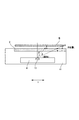
[Selection] Figure 3
Description
本発明は、原稿の画像を読み取る画像読取装置及びこれを備える画像形成装置に関する。 The present invention relates to an image reading apparatus that reads an image of a document and an image forming apparatus including the image reading apparatus.
一般に、デジタル複写機、ファクシミリ、イメージスキャナ等の画像形成装置においては、原稿を読み取る縮小光学系の画像読取装置が広く採用されている。画像読取装置は、光源から放射された原稿読み取り用の照明光を原稿に照射し、原稿からの反射光を集光して光電変換手段に結像させることにより画像の読み取りを行う。そのため、画像読取装置において原稿を正確に読み取るためには、原稿を載置台ガラスに密着させて照明光を正確に反射させる必要がある。 In general, in image forming apparatuses such as digital copying machines, facsimile machines, and image scanners, reduction optical system image reading apparatuses that read originals are widely used. The image reading apparatus reads an image by irradiating the original with illumination light for reading the original emitted from the light source, condensing the reflected light from the original and forming an image on the photoelectric conversion means. Therefore, in order for the image reading apparatus to accurately read the document, it is necessary to closely reflect the illumination light by bringing the document into close contact with the mounting table glass.
ここで、原稿を載置台ガラスに密着させるためには、原稿を載置する載置台ガラスに原稿を押圧する原稿圧板を密着させて原稿の浮き上がりを防止する必要がある。しかしながら、載置台ガラスに原稿圧板を密着させると、載置台ガラスに原稿圧板が張り付く場合があり、例えば、開閉自在の原稿圧板であれば支軸を中心に原稿圧板を開く際、原稿圧板を持ち上げるために形成された把持部等を破損させるおそれがある。 Here, in order to bring the document into close contact with the placing table glass, it is necessary to prevent the document from being lifted by bringing a document pressure plate that presses the document into close contact with the placing table glass on which the document is placed. However, when the original platen is brought into close contact with the platen glass, the original platen may stick to the platen glass. For example, if the original platen can be opened and closed, the original platen is lifted when the original platen is opened around the support shaft. Therefore, there is a risk of damaging the gripping portion and the like formed for this purpose.
これに対しては、原稿圧板と載置台ガラスとの密着性を解除する密着解除部材を原稿圧板と載置台ガラスとの間に設け、原稿圧板を持ち上げるときに原稿圧板と載置台ガラスの密着性を軽減させる画像読取装置が開示されている(例えば、特許文献1参照)。 For this, an adhesion release member for releasing the adhesion between the document pressure plate and the table glass is provided between the document pressure plate and the table glass, and the adhesion between the document pressure plate and the table glass is raised when the document pressure plate is lifted. Has been disclosed (see, for example, Patent Document 1).
しかしながら、特許文献1に開示の画像読取装置は、例えば、カールや、折り目、波打ち等のある原稿を原稿台ガラスに載置して原稿圧板で原稿を押圧すると、密着解除部材と原稿台ガラスとの高さの差分だけ原稿の浮き上がりが生じる。そのため、原稿の密着性が保持されず、読み取られた画像に乱れが生じるおそれがある。これは、画角が最も広い主走査方向端部ほど、画像の乱れが大きくなり易く、画像読取装置の小型化が進むにつれ、光路長も短くなり、画角の関係上、より端部が原稿浮きには不利な構成になる。
However, in the image reading device disclosed in
そこで、本発明は、載置台ガラスへの圧板部の貼り付きを抑制すると共に、原稿の浮き上がりを好適に抑制して画像品質の低下を低減させた画像読取装置及びこれを備える画像形成装置を提供することを目的とする。 Therefore, the present invention provides an image reading apparatus that suppresses sticking of the pressure plate portion to the mounting table glass and appropriately suppresses the lifting of the document to reduce deterioration in image quality, and an image forming apparatus including the image reading apparatus. The purpose is to do.
本発明は、原稿が載置される載置台ガラスと、前記載置台ガラスに載置した原稿を前記載置台ガラスに押圧するための、開閉自在な圧板部と、前記圧板部によって前記載置台ガラスに押圧された原稿の画像情報を、主走査方向と直交する副走査方向に移動しながら読み取る画像読取手段と、を備えた画像読取装置において、前記圧板部における原稿を前記載置台ガラスに押圧する押圧面には、前記圧板部を閉じた状態で、前記副走査方向における少なくとも一端に渡るように前記副走査方向に延びる空間部を形成する段差部が設けられている、ことを特徴とする画像読取装置に関する。 The present invention includes a placing table glass on which a document is placed, a pressure plate portion that is openable and closable for pressing the document placed on the placing table glass against the placing table glass, and the placing plate glass described above by the pressure plate portion. In an image reading apparatus comprising image reading means for reading image information of a document pressed by the document while moving in a sub-scanning direction perpendicular to the main scanning direction, the document on the pressure plate unit is pressed against the mounting table glass. The pressing surface is provided with a step portion that forms a space portion extending in the sub-scanning direction so as to extend to at least one end in the sub-scanning direction with the pressure plate portion closed. The present invention relates to a reading device.
本発明のように、副走査方向に延びる空間部を形成する段差部を圧板部に設けることにより、載置台ガラスへの圧板部の貼り付きを抑制すると共に、原稿の浮き上がりを好適に抑制して画像品質の低下を低減させることができる。 As in the present invention, by providing the pressure plate portion with a step portion that forms a space portion extending in the sub-scanning direction, it is possible to suppress sticking of the pressure plate portion to the mounting table glass and to suitably suppress the lifting of the document. A decrease in image quality can be reduced.
以下、本発明の実施形態に係る画像読取装置1について、図1から図3(b)を参照しながら説明する。図1は、本発明の実施形態に係る画像読取装置1を示す斜視図である。図2は、本実施形態に係る画像読取装置1の画像読取部4を示す断面図である。図3(a)は、本実施形態に係る画像読取装置1の圧板部3を開いた状態を示す図である。図3(b)は、図3(a)の圧板部3を閉じた状態を示す図である。
Hereinafter, an
図1に示すように、本発明の実施形態に係る画像読取装置1は、原稿Sを載置する載置台ガラス2と、載置された原稿Sを載置台ガラス2に押圧する圧板部3と、載置された原稿Sの原稿面の画像情報を読み取る画像読取手段としての画像読取部4と、を備える。また、画像読取装置1は、載置台ガラス2を支持し、画像読取部4を収容する読取装置本体15を備える。
As shown in FIG. 1, an
図2に示すように、画像読取部4は、載置台ガラス2の下方に配置されている。また、画像読取部4は、原稿Sを照射する発光部としての光源ランプ10と、原稿Sからの反射光を読み取る結像レンズ11と、反射光を結像レンズ11に導く複数のミラー12と、光電交換素子を一列に配置した受光部としてのラインCCD13と、を備える。光源ランプ10、結像レンズ11、複数のミラー12及びラインCCD13は、載置台ガラス2の下方に配置された光学箱9に一体的に収容されている。
As shown in FIG. 2, the
光源ランプ10は、主走査方向(図1に示すX方向をいい、以下、「主走査方向X」という)に沿った光を載置台ガラス2に載置された原稿Sに向かって照射する。原稿Sで反射された反射光は、複数のミラー12及び結像レンズ11によって構成される縮小光学部によって主走査方向Xにおいて縮小され、主走査方向Xの中央近傍に配置されたラインCCD13に入射される。ラインCCD13は、原稿Sの画像情報を反映した反射光を光電変換し、電子的な画像信号として出力する。このように、画像読取部4は、原稿からの反射を主走査方向Xにおいて縮小する縮小光学部と、縮小光学部で縮小された光を受け、原稿画像を読み取る読取センサであるラインCCD13とを備えている。
The
また、画像読取部4は、不図示のワイヤで不図示のモータと結合されており、モータの回転駆動により主走査方向Xと直交する副走査方向(図1に示すY方向をいい、以下、「副走査方向Y」という)に移動制御される。画像読取部4は、モータを正回転又は逆回転することにより、副走査方向Yへ移動し、載置台ガラス2上に載置された原稿Sの画像情報を読み取り、走査する。
Further, the
図3(a)及び図3(b)に示すように、圧板部3は、ヒンジ部5によって読取装置本体15に載置台ガラス2を開閉自在に支持されている。圧板部3は、圧板部本体3aと、原稿Sを載置台ガラス2に押圧する押圧面を構成する弾性部としての押圧部6と、圧板部本体3aと押圧部6との間に配置される弾性部としての弾性変形部7と、を備える。
As shown in FIGS. 3A and 3B, the
押圧部6は、弾性変形可能な合成樹脂材料(例えば、ABS樹脂等)により形成されており、主走査方向Xに傾斜した斜面が副走査方向Yに延びる段差部8を備える。段差部8は、光源ランプ10の照射による陰影が現れない角度の斜面状に形成されており、本実施形態においては、段差部8は、厚さ方向において0.4mmの段差Lが設けられるように形成されている。また、段差部8は、段差(L)に対して、原稿Sの画像情報を読み取る鉛直方向に対する角度(θ)が、
L・tanθ<20μm
となる位置に形成されている。
The
L ・ tanθ <20μm
It is formed in the position.
更に、段差部8は、押圧部6の副走査方向Yにおける両端に渡って形成されており、段差部8の主走査方向Xにおける両側(段差部8を境界とする主走査方向Xにおける両側)は、載置台ガラス2と密着するように載置台ガラス2と平行な平面状に形成されている。
Further, the
図3(b)に示すように、押圧部6は、ヒンジ部5によって開閉自在に支持された圧板部3を載置台ガラス2に対して閉操作されると、載置台ガラス2と接触することで段差部8が弾性変形し、載置台ガラス2との間に所定の空間部14を形成する。このとき、段差部8を境界とする主走査方向Xにおける両側は、平面状に形成されているため載置台ガラス2と密着する。
As shown in FIG. 3 (b), the
弾性変形部7は、弾性変形可能な合成樹脂材料(例えば、ウレタン樹脂等)により形成されており、段差部8が載置台ガラス2と接触して弾性変形することにより段差部8に押されて弾性変形する。つまり、弾性変形部7は、段差部8が空間部14を形成し易くなるように押圧部6の弾性変形を補助するクッションの役割を果たす。
The
次に、押圧部6の段差部8が空間部14を形成する弾性変形について、図3(a)及び図3(b)を参照しながら説明する。図3(a)に示すように、ヒンジ部5によって開閉自在に支持された圧板部3は、開状態においては、段差部8により押圧部6の押圧面には高低差(段差)がある状態のままである。一方、図3(b)に示すように、閉状態では、弾性変形部7のつぶれの反力及び載置台ガラス2からの押圧力によって押圧部6が変形し、押圧部6の段差部8を境界とする主走査方向Xにおける両側が原稿Sに密着する。このとき、段差部8は、弾性変形部7のつぶれの反力及び載置台ガラス2からの押圧力によって弾性変形するが原稿Sには密着せず、所定の空間部14を形成する。
Next, elastic deformation in which the stepped
ここで、図4を参照しながら原稿Sの画像情報を読み取る鉛直方向に対する角度(以下、「画角(θ)」という)と画像の乱れの関係について説明する。図4は、本実施形態に係る画像読取装置1の画角と画像の乱れとの関係を示す図である。
Here, the relationship between the angle with respect to the vertical direction for reading the image information of the document S (hereinafter referred to as “view angle (θ)”) and the image disturbance will be described with reference to FIG. FIG. 4 is a diagram illustrating the relationship between the angle of view and image distortion of the
図4に示す原稿Sは、Aの位置に副走査方向Yに向かう直線が描かれており、主走査方向Xにおける端部(A側の端部)が波打ちしている原稿とする。図4に示すように、載置台ガラス2から浮き上がっている原稿Sに書かれたAを読み取る時の画角はθである。これを原稿面上に変換すると、AはCの位置で認識される。一方、原稿Sが浮いていない場所においては、同じ画角θでは、AはBの位置で認識される。つまり、原稿Sが浮いている場所と浮いていない場所では、見た目上、B−Cのずれが生じ、読み取られた画像は、平面視でB−Cの幅を持った波線になってしまう。
The document S shown in FIG. 4 is a document in which a straight line in the sub-scanning direction Y is drawn at the position A and the end in the main scanning direction X (the end on the A side) is wavy. As shown in FIG. 4, the angle of view when reading A written on the document S floating from the placing
また、図4に示すように、画角がθ’の場所よりθの場所の方がB−Cの幅が大きい。つまり、同じ浮き量でもこのB−Cの値は主走査方向Xにおける端部側に行く程長くなり、直線が振幅の大きい波線に認識される。従って、原稿Sの主走査方向Xにおける端部付近で原稿Sが浮いてしまうと、画像の乱れはより大きくなる。 Also, as shown in FIG. 4, the width of BC is larger at the position of θ than the position of the angle of view θ ′. That is, even with the same floating amount, the value of BC becomes longer toward the end in the main scanning direction X, and the straight line is recognized as a wavy line with a large amplitude. Accordingly, when the document S floats near the edge of the document S in the main scanning direction X, the image is more disturbed.
この波線の幅は、例えば、20(μm)以下であれば、人の目には波線と認識されず、直線状に認識され得る。そのため、原稿Sの浮き量(=段差の高さ)をLとすると、
B−C=L・tanθ<20μm
となるようなθの位置であれば、原稿Sが所定量浮いていても画質上問題ない。従って、上記の位置に段差部8を設ければ、例えば、段差部8によって形成される空間部14にて原稿が浮いても、画角上画像の乱れはなく、画質は保たれる。
If the width of the wavy line is, for example, 20 (μm) or less, it is not recognized as a wavy line by human eyes but can be recognized as a straight line. Therefore, when the floating amount (= height of the step) of the document S is L,
B−C = L · tan θ <20 μm
If the position θ is such that the document S floats by a predetermined amount, there is no problem in image quality. Therefore, if the
以上のような構成を有する本実施形態に係る画像読取装置1によれば、以下のような効果を奏する。画像読取装置1は、弾性変形可能な弾性変形部7及び段差部8を有する押圧部6を備える。そのため、閉状態では、弾性変形部7のつぶれの反力によって押圧部6が変形し、原稿Sの主走査方向Xにおける両端部(主走査方向の両端側の領域)は、好適に載置台ガラス2に押圧される。また、画像読取装置1は、主走査方向Xにおける段差部8を境界とする両側を平面状にすることにより、原稿Sの主走査方向Xの端部(主走査方向Xの両端側の領域)を好適に押圧(密着させる)することができる。
The
また、段差部8を設けることにより、押圧部6と載置台ガラス2との間に空間部14を形成可能になる。閉状態で圧板部3に空間部14が形成されることにより、圧板部3を開状態にする際に段差部8の副走査方向Yの端部から、載置台ガラス2と押圧部6との間に空気が入りやすくなる。これにより、圧板部3を開放する際の、載置台ガラス2と押圧部6との密着による圧板部3の載置台ガラス2への貼り付きや破損が発生することを抑制することができる。
Further, by providing the
また、本実施形態においては、圧板部3を開放するに従い、押圧部6が元に戻ろうとして変形し、空間部14が大きくなるので、より空気が入りやすくなり密着による圧板部3の貼り付きや破損をより好適に防止することができる。
Further, in this embodiment, as the
以上、本発明の実施形態について説明したが、本発明は上述した実施形態に限定されるものではない。また、本発明の実施形態に記載された効果は、本発明から生じる最も好適な効果を列挙したに過ぎず、本発明による効果は、本発明の実施形態に記載されたものに限定されない。 As mentioned above, although embodiment of this invention was described, this invention is not limited to embodiment mentioned above. In addition, the effects described in the embodiments of the present invention only list the most preferable effects resulting from the present invention, and the effects of the present invention are not limited to those described in the embodiments of the present invention.
例えば、本実施形態においては、段差部8が、副走査方向Yと平行に延びたものを用いて説明したが本発明においてはこれに限定されない。段差部は、副走査方向Yに延びていればよく、副走査方向Yに平行でなく副走査方向Yに対して角度のある状態で延びていてもよい。また、段差部は、直線状に延びたものに限定されず、例えば、平面視で曲線状に形成されたものであってもよい。
For example, in the present embodiment, the stepped
また、本実施形態においては、副走査方向Yにおける両端に渡って形成された段差部8を1ヶ所設ける構成としたが本発明においてはこれに限定されない。例えば、図5(a)に示すように、副走査方向Yに延びる段差部8aを2ヶ所設ける構成であってよい。図5(a)で示した形態では、圧板部3を閉じた状態で、2つの段差部8aの間は載置台ガラス2と接することなく、載置台ガラス2との間で空間部14が形成される。副走査方向Yの端まで空間部14が通じているので圧板部3の開動作によって副走査方向Yの端部から空間部14に空気が入り込む。よって、圧板部3の載置台ガラス2への貼り付きを防止することができる。
In the present embodiment, one stepped
なお、圧板部3を閉じたときの弾性変形部7の反力による2つの段差部8aの間の部分の変形が生じないように構成してもよい。しかし、弾性変形部7の反力による2つの段差部8aの間の部分の変形が生じるように構成した方が好ましい。上述の実施形態と同様に圧板部3を開放するに従って、空間部14への空気の入り込みが促されるためである。
In addition, you may comprise so that the deformation | transformation of the part between the two level | step-
また、図5(b)に示すように、溝のような凹状の段差部8bを設ける構成であってもよい。更に、図6に示すように、副走査方向Yにおける両端に渡って形成されたものではなく、一端側のみに通じた段差8cを設ける構成であってもよい。
Moreover, as shown in FIG.5 (b), the structure which provides the concave level | step-
また、本実施形態においては、圧板部3は、原稿Sを押圧する機能のみの形態を述べたが本発明においてはこれに限定されない。圧板部は、例えば、ADF(自動原稿送り装置)と一体に形成されたものであってもよく、これを圧板部としてもよい。
Further, in the present embodiment, the
また、本実施形態においては、画像読取装置1を用いて説明したが、本発明においてはこれに限定されない。本発明は、画像読取装置と、画像読取装置で読み取られた画像をシートに形成する画像形成部とを備えた画像形成装置にも好適に使用することができる。
In the present embodiment, the
1 画像読取装置
2 載置台ガラス
3 圧板部
4 画像読取部(画像読取手段)
6 押圧部(弾性部)
7 弾性変形部(弾性部)
8 段差部
10 光源ランプ(発光部)
11 結像レンズ
12 ミラー
13 ラインCCD(受光部)
14 空間部
S 原稿
X 主走査方向
Y 副操作方向
DESCRIPTION OF
6 Pressing part (elastic part)
7 Elastic deformation part (elastic part)
8
11
14 Space S Document X Main scanning direction Y Sub-operation direction
Claims (5)
前記載置台ガラスに載置した原稿を前記載置台ガラスに押圧するための、開閉自在な圧板部と、
前記圧板部によって前記載置台ガラスに押圧された原稿の画像情報を、主走査方向と直交する副走査方向に移動しながら読み取る画像読取手段と、
を備えた画像読取装置において、
前記圧板部における原稿を前記載置台ガラスに押圧する押圧面には、前記圧板部を閉じた状態で、前記副走査方向における少なくとも一端に渡るように前記副走査方向に延びる空間部を形成する段差部が設けられている、
ことを特徴とする画像読取装置。 A table glass on which a document is placed;
An openable / closable pressure plate for pressing the document placed on the table glass against the table glass;
Image reading means for reading the image information of the document pressed against the table glass by the pressure plate unit while moving in the sub-scanning direction orthogonal to the main scanning direction;
In an image reading apparatus comprising:
A step for forming a space portion extending in the sub-scanning direction so as to extend over at least one end in the sub-scanning direction with the pressure plate portion closed, on the pressing surface that presses the original on the pressure plate portion against the table glass. Part is provided,
An image reading apparatus.
ことを特徴とする請求項1に記載の画像読取装置。 The pressure plate portion constitutes the pressing surface, is elastically deformed when the pressure plate portion is closed, and has the step portion that forms the space portion extending in the sub-scanning direction with the mounting glass. Comprising
The image reading apparatus according to claim 1.
ことを特徴とする請求項1又は2に記載の画像読取装置。 The step portion is formed across both ends of the pressure plate portion in the sub-scanning direction.
The image reading apparatus according to claim 1, wherein the image reading apparatus is an image reading apparatus.
前記段差部は、前記圧板部が前記載置台ガラスに載置された原稿を押圧したときの前記載置台ガラスに対する前記空間部の高さをL、原稿の画像を読み取る鉛直方向に対する角度をθとすると、
L・tanθ<20μm
となるθの位置に形成される、
ことを特徴とする請求項1乃至3のいずれか1項に記載の画像読取装置。 The image reading unit includes a light emitting unit and a light receiving unit,
The stepped portion has a height L of the space with respect to the table glass when the pressure plate unit presses the document placed on the table glass, and θ is an angle with respect to a vertical direction for reading an image of the document. Then
L ・ tanθ <20μm
Formed at the position of θ,
The image reading apparatus according to claim 1, wherein the image reading apparatus is an image reading apparatus.
前記画像読取装置で読み取られた画像をシートに形成する画像形成部と、を備えた、
ことを特徴とする画像形成装置。
An image reading apparatus according to any one of claims 1 to 4,
An image forming unit that forms an image read by the image reading device on a sheet,
An image forming apparatus.
Priority Applications (2)
| Application Number | Priority Date | Filing Date | Title |
|---|---|---|---|
| JP2010257145A JP5721402B2 (en) | 2010-11-17 | 2010-11-17 | Image reading apparatus and image forming apparatus |
| US13/286,626 US8675265B2 (en) | 2010-11-17 | 2011-11-01 | Image reading apparatus |
Applications Claiming Priority (1)
| Application Number | Priority Date | Filing Date | Title |
|---|---|---|---|
| JP2010257145A JP5721402B2 (en) | 2010-11-17 | 2010-11-17 | Image reading apparatus and image forming apparatus |
Publications (2)
| Publication Number | Publication Date |
|---|---|
| JP2012109806A true JP2012109806A (en) | 2012-06-07 |
| JP5721402B2 JP5721402B2 (en) | 2015-05-20 |
Family
ID=46047518
Family Applications (1)
| Application Number | Title | Priority Date | Filing Date |
|---|---|---|---|
| JP2010257145A Active JP5721402B2 (en) | 2010-11-17 | 2010-11-17 | Image reading apparatus and image forming apparatus |
Country Status (2)
| Country | Link |
|---|---|
| US (1) | US8675265B2 (en) |
| JP (1) | JP5721402B2 (en) |
Citations (7)
| Publication number | Priority date | Publication date | Assignee | Title |
|---|---|---|---|---|
| JPS60159428U (en) * | 1984-03-29 | 1985-10-23 | キヤノン株式会社 | Original crimping device |
| JPS6374636U (en) * | 1986-11-05 | 1988-05-18 | ||
| JPH01144040A (en) * | 1987-12-01 | 1989-06-06 | Canon Inc | Original platen device |
| JPH0213353U (en) * | 1988-07-08 | 1990-01-26 | ||
| JPH10221788A (en) * | 1996-12-06 | 1998-08-21 | Ricoh Co Ltd | Document size detector |
| JP2006067051A (en) * | 2004-08-25 | 2006-03-09 | Konica Minolta Business Technologies Inc | Original pressing device and image scanner |
| JP2009210682A (en) * | 2008-03-03 | 2009-09-17 | Seiko Epson Corp | Document reader |
Family Cites Families (4)
| Publication number | Priority date | Publication date | Assignee | Title |
|---|---|---|---|---|
| EP1260876B1 (en) * | 2001-05-25 | 2013-05-22 | Ricoh Company, Ltd. | A platen cover, image scanning device and image forming apparatus with the cover |
| JP4235608B2 (en) | 2004-12-24 | 2009-03-11 | キヤノン株式会社 | Image reading device |
| JP4182072B2 (en) | 2005-03-02 | 2008-11-19 | キヤノン株式会社 | Image reading apparatus and image expansion / contraction correction method |
| JP4073032B2 (en) | 2005-04-08 | 2008-04-09 | キヤノン株式会社 | Image reading apparatus and image forming apparatus |
-
2010
- 2010-11-17 JP JP2010257145A patent/JP5721402B2/en active Active
-
2011
- 2011-11-01 US US13/286,626 patent/US8675265B2/en active Active
Patent Citations (7)
| Publication number | Priority date | Publication date | Assignee | Title |
|---|---|---|---|---|
| JPS60159428U (en) * | 1984-03-29 | 1985-10-23 | キヤノン株式会社 | Original crimping device |
| JPS6374636U (en) * | 1986-11-05 | 1988-05-18 | ||
| JPH01144040A (en) * | 1987-12-01 | 1989-06-06 | Canon Inc | Original platen device |
| JPH0213353U (en) * | 1988-07-08 | 1990-01-26 | ||
| JPH10221788A (en) * | 1996-12-06 | 1998-08-21 | Ricoh Co Ltd | Document size detector |
| JP2006067051A (en) * | 2004-08-25 | 2006-03-09 | Konica Minolta Business Technologies Inc | Original pressing device and image scanner |
| JP2009210682A (en) * | 2008-03-03 | 2009-09-17 | Seiko Epson Corp | Document reader |
Also Published As
| Publication number | Publication date |
|---|---|
| JP5721402B2 (en) | 2015-05-20 |
| US8675265B2 (en) | 2014-03-18 |
| US20120120460A1 (en) | 2012-05-17 |
Similar Documents
| Publication | Publication Date | Title |
|---|---|---|
| US8830542B2 (en) | Illumination apparatus and image reading apparatus | |
| CN103782581B (en) | Original document reading apparatus | |
| WO2012176487A1 (en) | Image scanning unit | |
| CN100409656C (en) | Image sensor unit and image reading device | |
| US20160150109A1 (en) | Image reading device and image forming apparatus | |
| JP2013229316A (en) | Illumination apparatus, image sensor unit, image reading apparatus, and image forming apparatus | |
| EP1309169B1 (en) | Image reading apparatus | |
| US6867886B2 (en) | Apparatus for viewing originals | |
| JP2016225888A (en) | LIGHTING DEVICE, IMAGE READING DEVICE, AND IMAGE FORMING DEVICE | |
| JP6097460B2 (en) | Image reading unit | |
| JP2010258543A (en) | Image sensor unit and image reader | |
| JP5703695B2 (en) | Image reading device | |
| JP5721402B2 (en) | Image reading apparatus and image forming apparatus | |
| JPH11289430A (en) | Image reading device and image forming device | |
| JP5264215B2 (en) | Image reading device | |
| JP2002077539A (en) | Image reading device | |
| JP2006174038A (en) | Image sensor unit | |
| JP6784605B2 (en) | Image reader and image forming device | |
| JP5045583B2 (en) | Image reading device | |
| JP4928598B2 (en) | Line-shaped illumination device and image reading device | |
| JP4384639B2 (en) | Image reading device | |
| JP3912544B2 (en) | Image reading device | |
| JP2008160582A (en) | Image reading apparatus and facsimile apparatus | |
| JP4174269B2 (en) | Image reading device | |
| JP2014126594A (en) | Image reader and image forming apparatus |
Legal Events
| Date | Code | Title | Description |
|---|---|---|---|
| RD04 | Notification of resignation of power of attorney |
Free format text: JAPANESE INTERMEDIATE CODE: A7424 Effective date: 20130228 |
|
| A621 | Written request for application examination |
Free format text: JAPANESE INTERMEDIATE CODE: A621 Effective date: 20131118 |
|
| A977 | Report on retrieval |
Free format text: JAPANESE INTERMEDIATE CODE: A971007 Effective date: 20141117 |
|
| A131 | Notification of reasons for refusal |
Free format text: JAPANESE INTERMEDIATE CODE: A131 Effective date: 20141202 |
|
| A521 | Written amendment |
Free format text: JAPANESE INTERMEDIATE CODE: A523 Effective date: 20150202 |
|
| TRDD | Decision of grant or rejection written | ||
| A01 | Written decision to grant a patent or to grant a registration (utility model) |
Free format text: JAPANESE INTERMEDIATE CODE: A01 Effective date: 20150224 |
|
| A61 | First payment of annual fees (during grant procedure) |
Free format text: JAPANESE INTERMEDIATE CODE: A61 Effective date: 20150324 |
|
| R151 | Written notification of patent or utility model registration |
Ref document number: 5721402 Country of ref document: JP Free format text: JAPANESE INTERMEDIATE CODE: R151 |