JP2012111186A - Molding apparatus and molding method - Google Patents
Molding apparatus and molding method Download PDFInfo
- Publication number
- JP2012111186A JP2012111186A JP2010263776A JP2010263776A JP2012111186A JP 2012111186 A JP2012111186 A JP 2012111186A JP 2010263776 A JP2010263776 A JP 2010263776A JP 2010263776 A JP2010263776 A JP 2010263776A JP 2012111186 A JP2012111186 A JP 2012111186A
- Authority
- JP
- Japan
- Prior art keywords
- opening
- cavity
- gate
- gas
- closing
- Prior art date
- Legal status (The legal status is an assumption and is not a legal conclusion. Google has not performed a legal analysis and makes no representation as to the accuracy of the status listed.)
- Granted
Links
Images



Landscapes
- Moulds For Moulding Plastics Or The Like (AREA)
Abstract
【課題】成形品の品質低下、薄肉のキャビティ内への溶融素材の充填性の阻害及び金型や摺動部材の摺動動作の阻害をそれぞれ防止した成形装置と成形方法の提供。
【解決手段】薄肉成形品の形状に形成されたキャビティ5と、キャビティ5に溶融素材を送りこむ射出口7と、を金型2に設けた成形装置(と成形方法)において、キャビティ5に設けられた開口部(12〜14)から金型2の外部に連通する通気路(21〜23)と、自動開閉機構(15〜17)を介して前記開口部の閉塞位置から開放位置まで進退動作することにより、開口部(12〜14)を開閉する開閉部材(18〜20)と、を設け、開閉部材(18〜20)は、キャビティ5内の溶融素材が開口部(12〜14)に到達する前に前記開口部を閉塞するようにした。
【選択図】図2[PROBLEMS] To provide a molding apparatus and a molding method that prevent the deterioration of the quality of a molded product, the impediment to filling of a molten material into a thin-walled cavity, and the impediment to sliding movement of a mold or a sliding member.
In a molding apparatus (and molding method) in which a cavity 5 formed in the shape of a thin molded article and an injection port 7 for feeding a molten material into the cavity 5 are provided in a mold 2 (and a molding method), the cavity 5 is provided. Through the vents (21-23) communicating from the opening (12-14) to the outside of the mold 2 and the automatic opening / closing mechanism (15-17) to advance and retract from the closed position to the open position of the opening. Thus, an opening / closing member (18-20) for opening / closing the opening (12-14) is provided, and the opening / closing member (18-20) is such that the molten material in the cavity 5 reaches the opening (12-14). Before opening, the opening was closed.
[Selection] Figure 2
Description
本発明は、溶融素材から発生するガスを原因とした成形品の不具合を防止した成形装置と成形方法に関する発明である。 The present invention relates to a molding apparatus and a molding method that prevent problems of molded products caused by gas generated from a molten material.
特許文献1には、薄肉成形品である車両用灯具の前面カバーを成形する成形装置が示されている。特許文献1に記載された成形装置は、パーティングラインPLを間に挟んで上下2つの金型(100,200)を有し、前記金型間には、薄肉の樹脂製前面カバー形状に形成されたキャビティCが設けられる。キャビティCは、ゲート96、ランナ(94,95)、スプルー91a及び樹脂注入口93と連通し、これらを介して樹脂注入ノズル90から溶融樹脂の供給を受ける。樹脂製の前面カバーは、キャビティC内に充填された樹脂が冷却された後、金型(100,200)を開くことによって得られる。
近年においては、車両用灯具の軽量化を図る観点から、より薄肉の成形品を成形する要求が高まっている。ポリカーボネート等の溶融樹脂は、流動性が低いため、薄肉のキャビティへの充填性を向上させるためにより高温に加熱され、加熱された溶融樹脂は、キャビティ内にガスを発生させる。ガスに含まれる粒子は、キャビティ内に残留して内壁に付着して成形品の意匠面にくもりや変色を発生させたり、溶融樹脂の流動性を悪化させてキャビティへの充填性を阻害したり、金型の摺動部位や金型内の摺動部材に付着して動作を阻害する点で問題がある。 In recent years, from the viewpoint of reducing the weight of a vehicular lamp, there has been an increasing demand for molding a thinner molded product. Since a molten resin such as polycarbonate has low fluidity, it is heated to a higher temperature in order to improve the filling property into a thin cavity, and the heated molten resin generates gas in the cavity. Particles contained in the gas remain in the cavity and adhere to the inner wall to cause cloudiness and discoloration on the design surface of the molded product, or deteriorate the fluidity of the molten resin and impair the filling property to the cavity. There is a problem in that the adhesion to the sliding portion of the mold or the sliding member in the mold obstructs the operation.
そのような観点から、金型においては、溶融樹脂が流動していくキャビティの下流域のパーティングラインに沿って金型外部に連通する通気路を設け、流動する溶融樹脂の前方に発生するガスを確実に金型の外部に排出することが望ましいと考えられる。しかし、通気路を広く形成した場合には、ガス抜けが良くなる反面、溶融樹脂が通気路に流入して成形品にバリを発生させる点で問題があり、バリを減少させるために通気路を狭く形成した場合には、ガスが十分に排出されない点で問題がある。 From such a viewpoint, in the mold, a gas generated in front of the flowing molten resin is provided in the mold by providing a vent path communicating with the outside of the mold along the parting line in the downstream area of the cavity through which the molten resin flows. It is considered desirable to discharge the gas to the outside of the mold. However, when the air passage is formed wide, gas escape is improved, but there is a problem in that the molten resin flows into the air passage and generates burrs in the molded product. If it is formed narrow, there is a problem in that the gas is not sufficiently discharged.
本願発明は、上記課題に鑑みて、成形品に形成されるバリを抑制しつつキャビティ内のガスを確実に金型の外部に排出させることにより、成形品の品質を保ち、キャビティ内への溶融素材の充填性の阻害防止と、更に金型や摺動部材の摺動動作の阻害防止を図る成形装置と成形方法を提供するものである。 In view of the above problems, the invention of the present application maintains the quality of the molded product by melting the gas in the cavity to the outside of the mold while suppressing burrs formed in the molded product, and melting into the cavity. The present invention provides a molding apparatus and a molding method that prevent the filling of the material from being hindered and further prevent the sliding movement of the mold and the sliding member.
前記課題を解決するために請求項1の成形装置は、成形品形状に形成されたキャビティと、前記キャビティに溶融素材を送りこむ射出口と、を金型に設けた成形装置において、前記キャビティに設けられた開口部から前記金型の外部に連通する通気路と、自動開閉機構を介して前記開口部の閉塞位置から開放位置まで進退動作することにより、前記開口部を開閉する開閉部材と、を設け、前記開閉部材は、キャビティ内の溶融素材が前記開口部に到達する前に前記開口部を閉塞するように構成した、
(作用)キャビティ内に送り込まれた溶融素材から発せられたガスは、キャビティ内に残留せず、流動方向下流の開口部から通気路を通り、金型の外部に確実に排出されるため、キャビティ内の溶融素材の流動性が低下せず、金型や摺動部材の摺動性も確保される。一方、開口部は、溶融素材の到達前に開閉部材によって閉塞されるため、溶融素材が通気路に侵入出来ない。その結果、出来上がった成形品には、バリや意匠面のくもり等が発生しにくくなる。
In order to solve the above-mentioned problems, the molding apparatus according to
(Function) The gas emitted from the molten material fed into the cavity does not remain in the cavity, and is reliably discharged to the outside of the mold through the air passage from the opening downstream in the flow direction. The fluidity of the molten material is not lowered, and the slidability of the mold and the sliding member is ensured. On the other hand, since the opening is closed by the opening / closing member before the molten material reaches, the molten material cannot enter the ventilation path. As a result, burrs and clouding of the design surface are less likely to occur in the finished molded product.
請求項2は、請求項1に記載の成形装置であって、前記開口部の断面積を0.5mm2以上にした。 A second aspect of the present invention is the molding apparatus according to the first aspect, wherein the sectional area of the opening is 0.5 mm 2 or more.
(作用)開口部の断面積を0.5mm2以上にすることで、溶融素材から発せられるガスが、通気路から金型の外部に更に排出されやすくなる。 (Operation) By setting the sectional area of the opening to 0.5 mm 2 or more, the gas generated from the molten material is more easily discharged from the vent path to the outside of the mold.
また、請求項3は、請求項1または2に記載の成形装置であって、前記開口部が溶融素材の流動方向に沿ってキャビティに複数設けられ、前記開閉部材が前記開口部毎に複数設けられ、前記各開閉部材は、キャビティ内の溶融素材が前記各開口部に到達する直前に該到達する直前の開口部を順に閉塞するようにした。 A third aspect of the present invention is the molding apparatus according to the first or second aspect, wherein a plurality of the openings are provided in the cavity along the flow direction of the molten material, and a plurality of the opening / closing members are provided for the openings. The opening / closing members sequentially close the openings immediately before the molten material in the cavity reaches the openings.
(作用)キャビティ内のガスは、上流に開口する開口部から順に排出される。言い換えると、キャビティ内のガスは、上流の開口部で排出されなくても更に下流の開口部から排出されるため、更に確実に金型の外に排出される。また、溶融素材が接近した開口部が接近した順に閉塞されるため、成形品のバリも低減される。 (Operation) The gas in the cavity is sequentially discharged from the opening opening upstream. In other words, even if the gas in the cavity is not exhausted from the upstream opening, it is exhausted from the downstream opening, so that it is more reliably discharged out of the mold. Moreover, since the opening part which the molten material approached is obstruct | occluded in the order which approached, the burr | flash of a molded product is also reduced.
請求項4は、請求項1から3のうちいずれかに記載の成形装置であって、前記成形品が車両用灯具レンズであり、前記開口部が前記キャビティにおいて前記車両用灯具レンズの意匠面と接しない位置に設けられたことを特徴とする、請求項1から3のうちいずれかに記載の成形装置。
A fourth aspect of the present invention is the molding apparatus according to any one of the first to third aspects, wherein the molded product is a vehicle lamp lens, and the opening portion is a design surface of the vehicle lamp lens in the cavity. The molding apparatus according to
(作用)出来上がった成形品には、キャビティの開口部位置において、閉塞された開口部形状の跡が形成されることがあるが、かかる開口部形状の跡は、車両用灯具レンズの意匠面に形成された場合に品質面で特に問題になる。請求項4の成形装置においては、キャビティにおいて車両用灯具レンズの意匠面(車体に灯具を組み付けた状態において車体から露出する部分)が形成される以外の場所に通気路の開口部を設けているため、開口部形状の跡が形成されたとしても、意匠面に形成されることがない。 (Operation) In the finished molded product, a trace of the closed opening shape may be formed at the position of the opening of the cavity. The trace of the opening shape is formed on the design surface of the vehicle lamp lens. When formed, it becomes a problem particularly in terms of quality. According to a fourth aspect of the present invention, the vent passage opening is provided at a location other than where the design surface of the vehicle lamp lens (the portion exposed from the vehicle body when the lamp is assembled to the vehicle body) is formed in the cavity. Therefore, even if the trace of the opening shape is formed, it is not formed on the design surface.
請求項5の成形方法は、前記成形品形状に形成されたキャビティと、前記キャビティに溶融素材を送りこむ射出口と、前記キャビティに設けられた開口部から(金型の)外部に連通する通気路と、を金型に有し、更に自動開閉機構を介して前記開口部の閉塞位置から開放位置まで進退動作することにより、前記開口部を開閉する開閉部材を有する成形装置において、前記キャビティ内に溶融素材を送り込み、キャビティ内を流動する溶融素材が前記開口部に近づくと前記開口部を閉塞するようにした。
The molding method according to
(作用)キャビティ内に送り込まれた溶融素材から発せられるガスは、キャビティ内に残留して内壁や摺動部位などに粒子を付着させることがなく、流動方向下流の開口部から通気路を通り、金型の外部に確実に排出される。その結果、キャビティ内の溶融素材の流動性が阻害されず、金型や摺動部材の摺動性も確保される。一方、開口部は、溶融素材の到達前に開閉部材によって閉塞されるため、溶融素材が通気路に侵入出来ない。その結果、出来上がった成形品には、バリや意匠面のくもり等が発生しにくくなる。 (Operation) Gas emitted from the molten material sent into the cavity does not remain in the cavity and attach particles to the inner wall or sliding part, and passes through the ventilation path from the opening downstream in the flow direction. It is reliably discharged outside the mold. As a result, the fluidity of the molten material in the cavity is not hindered, and the slidability of the mold and the sliding member is ensured. On the other hand, since the opening is closed by the opening / closing member before the molten material reaches, the molten material cannot enter the ventilation path. As a result, burrs and clouding of the design surface are less likely to occur in the finished molded product.
請求項1の成形装置によれば、溶融素材から発生したガスの粒子がキャビティの内壁や金型の摺動部位等に付着しにくくなるため、成形品の品質が保たれ、薄肉のキャビティ内への溶融素材の充填性が阻害されず、更に金型の摺動部位や摺動部材の摺動動作の阻害も防止される。 According to the molding apparatus of the first aspect, gas particles generated from the molten material are less likely to adhere to the inner wall of the cavity, the sliding portion of the mold, and the like, so that the quality of the molded product is maintained, and into the thin-walled cavity. The filling property of the molten material is not hindered, and the sliding part of the mold and the sliding operation of the sliding member are also prevented.
請求項2の成形装置によれば、開口部の断面積を適切な大きさとすることによって金型外部へのガスの排出が更に確実になるため、出来上がった成形品の品質が更に保たれ、薄肉のキャビティ内への溶融素材の充填性が更に阻害されなくなる。
According to the molding apparatus of
請求項3の成形装置によれば、通気路に連通する開口部を上流から下流に向けてキャビティに複数設けることで金型外部へのガスの排出が更に確実になるため、出来上がった成形品の品質が更に保たれ、薄肉のキャビティ内への溶融素材の充填性が更に阻害されなくなる。
According to the molding apparatus of
請求項4の成形装置によれば、車両用灯具レンズの意匠面に開口部形状の跡が形成されないため、成形される車両用灯具レンズの意匠面の品質が低下しない。 According to the molding apparatus of the fourth aspect, since the trace of the opening shape is not formed on the design surface of the vehicle lamp lens, the quality of the design surface of the molded vehicle lamp lens does not deteriorate.
請求項5の成形方法によれば、溶融素材から発生したガスの粒子がキャビティの内壁に付着しにくくなって、成形品のバリやくもり等が発生しにくくなるため、高品質の成形品を成形出来る。また、薄肉のキャビティ内への溶融素材の充填性が更に阻害されなくなる。
According to the molding method of
まず、図1から図3により本発明における成形装置の実施例を説明する。 First, an embodiment of the molding apparatus according to the present invention will be described with reference to FIGS.
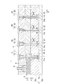
図1には、本実施例の成形装置が示されている。図1の成形装置1は、金型2、溶融樹脂の射出装置3,複数のガス抜き装置4によって構成される。
FIG. 1 shows the molding apparatus of this embodiment. The
本実施例の金型2は、パーティングラインPLを介して2分割される金型構成部材(2a,2b)からなり、金型(2a,2b)の下面及び上面の間には、薄肉成形品の形状に基づいて形成されたキャビティ5が設けられている。
The
射出装置3は、図示しない制御装置によって溶融樹脂(請求項の溶融素材)の射出を制御される成形機ノズル6,射出された溶融樹脂をキャビティ5に開口する射出ゲート7(請求項の射出口)に導く樹脂送通路8、射出ゲート7を開閉させる射出ゲート開閉装置9によって構成される。射出ゲート開閉装置9は、射出ゲート7の自動開閉機構であるエアシリンダ10と、図示しない制御機構に制御されたエアシリンダ10によって樹脂送通路8の内部を進退する先端部11aが射出ゲート7に当接し(閉塞)、または射出ゲート7から離間(開放)する射出バルブピン11によって構成される。尚、射出ゲート7の開閉装置においては、自動開閉機構としてモーター機構や油圧機構を採用しても良く、射出ゲート7は、図1に示すキャビティ5の上方のみならず、側方に開口させても良い。
The
また、本実施例の複数のガス抜き装置4は、3つのガス抜き装置(4A〜4C)によって構成される。またキャビティ5には、射出ゲート7の位置を流動する溶融樹脂の上流位置と考えた場合、そこから下流方向(図1,2のF方向)に複数のガス抜きゲート(請求項の開口部、符号12〜14)が設けられる。尚、ガス抜き装置(4A〜4C)とガス抜きゲート(12〜14)の数は、一つずつでも良く、複数の場合3つに限られない。
Moreover, the
尚、図3に薄肉成形品の一例として車両用灯具レンズ24を示す。符号25は、車両用灯具(図示せず)の車両への取り付け後に車両の外部に露出する意匠面を示し、符号26は、取り付け後に外部に露出することのない、車両用灯具へのレンズの取付部を示す。ガス抜きゲート(12〜14)は、キャビティ5において図3のようにレンズの取付部26に対応した位置に開口させる。出来上がった成形品には、ガス抜きゲート(12〜14)を後述する方法で閉塞することによって大きなバリが出来ないものの、閉塞されたガス抜きゲート(12〜14)の周辺で樹脂が固まることにより、ガス抜きゲート(12〜14)の跡が付く場合がある。ガス抜きゲート(12〜14)を意匠面25に対応する位置に設けなければ、出来上がった成形品の意匠面25にガス抜きゲートの跡が形成されることもないため、意匠面の品質低下が防止される。尚、キャビティ5においては、ガス抜きゲート(12〜14)を意匠面25のセンターマーク位置に開口させ、意匠面25に形成されるガス抜きゲート(12〜14)の跡を意匠面のセンターマークとして利用してもよい。
FIG. 3 shows a
ガス抜き装置(4A〜4C)は、エアシリンダ(請求項の自動開閉機構、符号15〜17)と、エアシリンダ(15〜17)によってガス抜きゲート(12〜14)と連通する通気路(21〜23)の内側を進退動作可能に構成されたガス抜きバルブピン(請求項の開閉部材、符号18〜20)によって構成される。通気路(21〜23)は、それぞれ互いに連通し、連通する通気路(21〜23)は、金型外部への開口部(図示せず)を有する。ガス抜きバルブピンの先端(18a〜20a)は、各ガス抜きバルブピン(18〜20)の進退動作に伴って進退動作し、対応する各ガス抜きゲート(12〜14)に当接することによって各ガス抜きゲート(12〜14)を閉塞すると共に各ガス抜きゲート(12〜14)から離間することで各ガス抜きゲート(12〜14)を開放する。エアシリンダ(15〜17)の動作は、図示しない制御機構によってそれぞれが独立して制御され、各ガス抜きバルブピン(18〜20)は、独立して進退動作することで、各ガス抜きゲート(12〜14)を開閉する。キャビティ5は、開放されたガス抜きゲート(12〜14)、通気路(21〜23)及び金型外部への開口部(図示せず)を介して金型外部(外気)に連通する。
The gas venting devices (4A to 4C) include an air cylinder (automatic opening / closing mechanism,
次に、図1〜4により、本発明の成形方法を説明する。射出ゲート開閉装置9によって射出バルブピン11の先端11aを図1のU方向に上昇させ、射出ゲート7を開放させた状態で成型機ノズル6に射出動作をさせると、溶融樹脂がキャビティ5内に射出される。
Next, the molding method of the present invention will be described with reference to FIGS. When the injection gate opening /
ガス抜きバルブピン(18〜20)は、エアシリンダ(15〜17)によって、成形機ノズル6による射出動作前、射出動作時、または射出動作後の所定時のいずれかにおいてU方向に上昇し、ガス抜きゲート(12〜14)から離間した位置(請求項の開放位置)に配置される。尚、溶融樹脂によるガスは、キャビティ5内への溶融樹脂の射出時に最も多くキャビティ5内に溜まる。従って、成型機ノズル6による射出動作は、ガス抜きゲート(12〜14)を予め開放した状態で行うことがキャビティ5内のガスを金型の外に迅速に排出する観点からより望ましい。
The gas vent valve pins (18 to 20) are raised in the U direction by the air cylinders (15 to 17) either before the injection operation by the molding machine nozzle 6, during the injection operation, or at a predetermined time after the injection operation. It arrange | positions in the position (open position of a claim) spaced apart from the extraction gate (12-14). It should be noted that most of the gas from the molten resin is accumulated in the
キャビティ内を流動する樹脂の前方(下流側)には、高温によるガスが発生する。溶融樹脂が下流F方向に向けて流動すると、発生したガスは、キャビティ5内の空気と共に溶融樹脂によって下流側(図1,2の点線矢印方向)に押される。ガスと空気の大半は、開放されたガス抜きゲート12から通気路21に入り、金型の外部に排出され、ガス抜きゲート12に入りきらなかった少量のガスと空気もまた、下流のガス抜きゲート(13,14)から通気路(22,23)を通って金型の外部に確実に排出される。
Gas due to high temperature is generated in front (downstream side) of the resin flowing in the cavity. When the molten resin flows in the downstream F direction, the generated gas is pushed downstream (in the direction of the dotted arrows in FIGS. 1 and 2) by the molten resin together with the air in the
溶融樹脂が図2のF方向に進み、溶融樹脂の先端FPが直近のガス抜きゲート12の直前に接近すると、溶融樹脂がガス抜きゲート12に到達する前にエアシリンダ15によってガス抜きバルブピン18が下降し、ガス抜きバルブピンの先端18aがガス抜きゲート12を閉塞する。溶融樹脂は、ガス抜きゲート12が閉塞されているため、通気路21に入り込むことなくキャビティ5内を下流に流動し、発生したガスは、ガス抜きゲート(13、14)から順番に金型外部に排出される。溶融樹脂の先端FPが次なるガス抜きゲート13の直前に接近すると、エアシリンダ16によってガス抜きバルブピン19が下降してガス抜きゲート13が閉塞される。
When the molten resin advances in the direction F in FIG. 2 and the front end FP of the molten resin approaches immediately before the nearest
溶融樹脂は、通気路22に入り込むことなくキャビティ5内を通過し、ガス抜きゲート14に接近すると、ガス抜きゲート14が閉塞されることによってキャビティ5の末端まで充填され、キャビティ内への充填が完了する。本実施例においては、開放したガス抜きゲート(12〜14)によって、キャビティ内を流動中の溶融樹脂から発生したガスと流動性を低下させるキャビティ内の空気をいち早く金型の外部に排出し、更に溶融樹脂が接近したガス抜きゲートをいち早く封鎖することにより、通気路(21〜23)に入り込んで成形品に形成されるはずのバリを防止している。また、本実施例においては、ガス抜きゲートを複数設けることにより、キャビティ内のガスの速やかな排出を可能にし、更に一部のガス抜きゲートを閉じても他のガス抜きゲートからのガスが排出されるようにすることで、より確実な排出を実現している。
When the molten resin passes through the
次に、図1から図4により、金型におけるガス抜きゲート開閉のタイミングについて詳細に説明する。図3の曲線A,A’,B,B’,C,C’は、キャビティ5内を流動する溶融樹脂のフローフロント(先端部)の位置を示す。曲線A,B,Cの位置は、溶融樹脂が当該曲線に到達した際にガス抜きバルブピン(18〜20)を閉塞位置に動作させれば、溶融樹脂が通気路(21〜23)に入ることなくガス抜きゲート(12〜14)を閉塞出来る限界の位置を示す。また、曲線A’,B’,C’の位置は、各ガス抜きゲート(12〜14)を通過した直後の溶融樹脂のフローフロント位置を示す。溶融樹脂は、図3の射出ゲート7から車両用灯具レンズ24の形状からなる薄肉のキャビティ5に流入し、キャビティ5内において図3の曲線A−A’−B−B’−C−C’の順に放射状に充填されていく。
Next, the timing of opening / closing the degassing gate in the mold will be described in detail with reference to FIGS. Curves A, A ′, B, B ′, C, and C ′ in FIG. 3 indicate the position of the flow front (tip portion) of the molten resin that flows in the
各ガス抜きゲート(12〜14)の開閉制御には、図示しない制御装置により、射出ゲート7が開放されて、溶融樹脂のキャビティ5への射出が開始されてから異なる所定時間経過後にガス抜きゲート(12〜14)を順に閉塞していくタイマー制御、圧力センサーをキャビティ5内の所定地に設置し、設置位置のガス圧が所定の内圧を超えたことを検知した場合に溶融樹脂が各ガス抜きゲート(12〜14)のいずれかに接近したものとして、接近したガス抜きゲートを閉塞させるガス圧制御、熱センサーを金型の各ガス抜きゲート(12〜14)周辺の所定位置に設置し、設置位置の温度が所定温度を超えたものと検知した場合に溶融樹脂が接近したものとして、該当するガス抜きゲートを閉塞させる金型温度制御等がある。本実施例においては、一例としてタイマー制御の具体例を示す。
For opening / closing control of each degassing gate (12-14), the degassing gate is opened after a predetermined time has elapsed since the
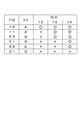
射出ゲート7の開放から溶融樹脂が各ガス抜きゲート(12〜14)に到達するまでの時間は、キャビティ内におけるガス抜きゲートの設置位置や、成形品の形状(キャビティの薄さや広さ)に応じて異なる。図4の表の符号T欄は、充填開始後からの経過時間を示し、符号FF欄は、図3の溶融樹脂のフローフロント位置を示し、O/C欄(OPEN/CLOSE欄)は、ガス抜きゲート(12〜14)の開閉状況を示す。O/C欄の○は、ガス抜きゲート(12〜14)に対応する各ガス抜きバルブピン(18〜20)が開放位置まで上昇してガス抜きゲートを開放していることを示し、×は、ガス抜きバルブピンがガス抜きゲートの閉塞位置まで下降してガス抜きゲートを閉塞していることを示す。
The time from the opening of the
射出ゲート開閉装置9に射出ゲート7の開放信号(射出バルブピン11を開放位置まで上昇させる信号)が送信されて射出バルブピン11が上昇仕始めた時を充填開始時とした場合、本実施例においては、溶融樹脂のフローフロントが、充填開始から1.0秒、2,0秒及び3.0秒経過後に通気路(21〜23)へ溶融樹脂を侵入させることなくガス抜きバルブピン(18〜20)を降下させてガス抜きゲート(12〜14)を閉塞出来る限界位置を示す曲線A、曲線B及び曲線Cの位置にそれぞれ到達するものとしている。
In this embodiment, when the injection gate opening /
従って、本実施例においては、タイマーを利用した制御装置(図示せず)を用い、充填開始から1.0秒後にガス抜きゲート12の閉塞信号をガス抜き装置4Aに送信して、ガス抜きバルブピン18を開放位置から閉塞位置に下降させ、更に充填開始から2,0秒及び3.0秒経過後にそれぞれガス抜きゲート(13,14)の閉塞信号をガス抜き装置(4B,4C)に送信して、ガス抜きバルブピン(19,20)を開放位置から閉塞位置に順に下降させる。その結果、本実施例の製造装置とその製造方法においては、溶融樹脂の到達前にガス抜きゲート(12〜14)が閉塞されるため、出来上がった成形品には、通気路(21〜23)に入り込んだ溶融樹脂によるバリが発生しない。また、通気路に溶融樹脂が入り込まないため、ガス抜きバルブピン(18〜20)を含むエアシリンダ(15〜17)の稼働部位に付着した樹脂が固化することにより、ガス抜きゲート(12〜14)の開閉動作が阻害される不具合も発生しない。更に、本実施例においては、ガス抜きゲートの痕が出来上がった成形品に形成されたとしても、車両用灯具の取付部26にしか形成されず、意匠面25に形成されないため、品質の高い意匠面が形成される。
Accordingly, in this embodiment, a control device (not shown) using a timer is used, and a closing signal for the
ここで、本実施例におけるガス抜きゲート(12〜14)の好適な断面積について図5によって説明する。出願に先立ち本願発明者は、ガス抜きゲート(12〜14)の断面積を変化させた場合において、溶融樹脂がキャビティ内に発生するガスによるガス圧がどのように変化するかを実験で確認した。キャビティ内のガスの排出性は、測定されたガス圧が低いほど良いと考えられる。本実施例におけるガス抜きゲート(12〜14)の好適な断面積は、ガス抜きゲートを形成しないキャビティ内で計測されたガス圧と所定の断面積のガス抜きゲートを有するキャビティ内で計測されたガス圧とを比較して得られたガス圧の低減効果に基づいて定められたものである。 Here, the suitable cross-sectional area of the degassing gate (12-14) in a present Example is demonstrated with FIG. Prior to the application, the present inventor confirmed by experiment how the gas pressure due to the gas generated in the cavity of the molten resin changes when the cross-sectional area of the gas vent gate (12-14) is changed. . It is considered that the lower the measured gas pressure, the better the gas exhaustability in the cavity. A suitable cross-sectional area of the degassing gate (12 to 14) in this example was measured in a cavity having a degassing gate having a predetermined cross-sectional area and a gas pressure measured in a cavity not forming the degassing gate. It is determined based on the gas pressure reduction effect obtained by comparing with the gas pressure.
図5(a)は、キャビティに開口させるガス抜きゲート(12〜14)の断面積を共に異なる五種類の大きさにして成形試験を行うことによって溶融樹脂から発生するガスによるキャビティ内の内圧を測定した表であり、図5(b)は、キャビティ内の内圧とガス抜きゲートの断面積との関係を表すグラフである。 FIG. 5 (a) shows the internal pressure in the cavity due to the gas generated from the molten resin by performing a molding test with the cross-sectional areas of the degassing gates (12 to 14) opened in the cavity having five different sizes. FIG. 5B is a graph showing the relationship between the internal pressure in the cavity and the cross-sectional area of the degassing gate.
図5(a)の表の符号E欄は、ガス抜きゲートを設けなかった比較の基準となるキャビティ例BA(BASE)と、異なる断面積のガス抜きゲートを設けたキャビティ例1〜5を示す。また、符号G欄は、ガス抜きゲートの断面積(単位:mm2)を示し、符号P欄は、キャビティ内のガスの内圧(単位MPa)を示し、符号D欄は、ガス圧の低減効果を示す。また、図5(b)のグラフは、横軸がガス抜きゲートの断面積G(単位:mm2)を示し、縦軸がキャビティ内のガスの内圧P(単位MPa)を示す。 The column E in the table of FIG. 5A shows a cavity example BA (BASE) which is a reference for comparison in which no gas vent gate is provided, and cavity examples 1 to 5 in which gas vent gates having different cross-sectional areas are provided. . The G column indicates the cross-sectional area (unit: mm 2 ) of the degassing gate, the P column indicates the internal pressure (unit MPa) of the gas in the cavity, and the D column indicates the effect of reducing the gas pressure. Indicates. In the graph of FIG. 5B, the horizontal axis indicates the cross-sectional area G (unit: mm 2 ) of the degassing gate, and the vertical axis indicates the internal pressure P (unit MPa) of the gas in the cavity.
ここで、図5(b)に示すとおり、ガス抜きゲートの断面積が0以上0.5mm2未満の場合、キャビティ内のガス圧は、直線的かつ急激に減少するため、ガス抜きゲートにおいては、断面積の製造誤差によってガス抜き効率のバラツキが発生する。一方でガス抜きゲートの断面積が0.5mm2以上の場合、ガス圧の低下が曲線的に緩やかになるため、ガス抜きゲートにおいては、断面積に製造誤差があってもガス抜き効率のバラツキが発生しにくくなる点で望ましい。一方、断面積が0.5mm2のガス抜きゲート(12〜14)を有するキャビティ例1内のガス圧は、図5(a)に示すとおり0.68Mpaであり、ガス抜きゲートを設けなかった(断面積0)キャビティ例BA内のガス圧2.14Mpaを100%として比較すると、約68%低減されていることが判る点で更に望ましい。従って、ガス抜きゲート(12〜14)の断面積は、0.5mm2以上とすることが望ましい。 Here, as shown in FIG. 5B, when the cross-sectional area of the degassing gate is 0 or more and less than 0.5 mm 2 , the gas pressure in the cavity decreases linearly and rapidly. In addition, variations in gas venting efficiency occur due to manufacturing errors in the cross-sectional area. On the other hand, when the cross-sectional area of the degassing gate is 0.5 mm 2 or more, the decrease in gas pressure becomes curvilinear, so the degassing gate has a variation in degassing efficiency even if there is a manufacturing error in the cross-sectional area. It is desirable in that it is difficult to generate. On the other hand, the gas pressure in the cavity example 1 having the gas vent gates (12 to 14) having a cross-sectional area of 0.5 mm 2 was 0.68 Mpa as shown in FIG. 5A, and no gas vent gate was provided. (Cross sectional area 0) It is further desirable in that it is found that the gas pressure in the cavity example BA is reduced by about 68% when the gas pressure in the BA is assumed to be 100%. Therefore, the cross-sectional area of the gas vent gate (12 to 14) is desirably 0.5 mm 2 or more.
一方、図5(a)に示すとおり、ガス抜きゲートの断面積がそれぞれ1.0mm2、3.27mm2、5.54mm2、14.06mm2であるキャビティ例2〜5におけるガス圧は、それぞれ0.31Mpa、0.23Mpa、0.23Mpa、0.21Mpaになる。これらの結果と、キャビティ例BAの内圧が2.14Mpaを比較した場合、キャビティ例2〜5のガス圧は、キャビティ例BAのガス圧から、それぞれ、約86%、約89%、約89%、約90%低減され、キャビティからのガスの排出性が大幅に向上していることが判る。 Meanwhile, as shown in FIG. 5 (a), 1.0mm 2 cross-sectional area of the degassing gate, respectively, 3.27mm 2, 5.54mm 2, gas pressure in the cavity Examples 2-5 is 14.06Mm 2 is These are 0.31 Mpa, 0.23 Mpa, 0.23 Mpa, and 0.21 Mpa, respectively. When these results are compared with the internal pressure of the cavity example BA of 2.14 Mpa, the gas pressures of the cavity examples 2 to 5 are about 86%, about 89%, and about 89% from the gas pressure of the cavity example BA, respectively. It can be seen that the gas discharge from the cavity is greatly improved by about 90%.
一方、前記結果と図5(b)の曲線が示すとおり、キャビティ内のガス圧の低下は、ガス抜きゲートの断面積が1.0mm2以上になると、ほぼ横ばいになる。つまり、断面積が1.0mm2の以上のガス抜きゲートを形成しておけば、キャビティ内のガス圧は、ガス抜きゲートを設けない場合に比べて、およそ90%前後削減されることが判る。ガス圧の低下がほぼ一定になることは、キャビティからのガス抜き効率が、断面積の製造誤差の影響を殆ど受けない点で望ましい。 On the other hand, as shown by the above result and the curve of FIG. 5B, the decrease in the gas pressure in the cavity becomes almost flat when the cross-sectional area of the degassing gate is 1.0 mm 2 or more. That is, it can be seen that if a gas vent gate having a cross-sectional area of 1.0 mm 2 or more is formed, the gas pressure in the cavity is reduced by approximately 90% compared to the case where no gas vent gate is provided. . It is desirable that the decrease in gas pressure be almost constant in that the gas venting efficiency from the cavity is hardly affected by the manufacturing error of the cross-sectional area.
以上の結果から、ガス抜きゲート(12〜14)の断面積は、0.5mm2以上とすることが望ましく、更には、ガスの排出性の大幅な向上と、排出性のバラツキが殆どない点から。1.0mm2以上とすることがより一層望ましい。 From the above results, it is desirable that the cross sectional area of the gas vent gate (12 to 14) is 0.5 mm 2 or more, and further, there is no significant variation in gas discharge and almost no variation in discharge. From. It is even more desirable that the thickness be 1.0 mm 2 or more.
尚、本実施例においては、ガス抜きゲート(12〜14)を全て開放した状態で射出ゲート7から溶融樹脂をキャビティ5内に射出すると共に、溶融樹脂が接近したガス抜きゲートから順に閉塞しているが、ガス抜きゲートにおいては、溶融樹脂の射出時において、下流のガス抜きゲート(13,14)を閉塞させておき、射出ゲート7に一番近いガス抜きゲート12のみを開放させておいてもよい。その場合においては、例えば、溶融樹脂が接近した上流のガス抜きゲート12を閉塞させる際に、下流に隣接するガス抜きゲート13を開放させるようにし、溶融樹脂が接近した上流のガス抜きゲートを閉塞させつつ隣接する下流のガス抜きゲートを開放させることを順に繰り返すようにする。
In this embodiment, the molten resin is injected into the
キャビティ5内のガスは、ガス抜きゲート12の下流域が密閉されるため、当該密閉領域に入りにくくなる。その結果、開放されたガス抜きゲート12においては、ガスの排出が促進されキャビティ5内のガスが確実に排出される。また、ガス抜きゲート12の下流域においては、ガスと接触しにくくなるため、ガスの粒子がキャビティ5の内壁に付着することによる溶融樹脂の流動性の低下と、キャビティと連通する位置に配置された摺動部位等の摺動性の低下が更に防止される。更に、また、溶融樹脂が接近したガス抜きゲート12が閉塞されても、隣接する下流のガス抜きゲート13が速やかに開放されるため、ガスの排出性が低下しない。
The gas in the
1 成形装置
2 金型
5 キャビティ
7 射出ゲート(請求項1の射出口)
12〜14 ガス抜きゲート(請求項1の開口部)
15〜17 エアシリンダ(自動開閉機構)
18〜20 ガス抜きバルブピン(開閉部材)
21〜23 通気路
24 車両用灯具レンズ
25 車両用灯具レンズの意匠面
DESCRIPTION OF
12-14 Degassing gate (opening of claim 1)
15-17 Air cylinder (automatic open / close mechanism)
18-20 Degassing valve pin (opening / closing member)
21-23
Claims (5)
前記キャビティに設けられた開口部から前記金型の外部に連通する通気路と、自動開閉機構を介して前記開口部の閉塞位置から開放位置まで進退動作することにより、前記開口部を開閉する開閉部材と、を設け、
前記開閉部材は、キャビティ内の溶融素材が前記開口部に到達する前に前記開口部を閉塞することを特徴とする成形装置。 In a molding apparatus in which a cavity formed in the shape of a molded product and an injection port for feeding a molten material into the cavity are provided in a mold,
Opening and closing that opens and closes the opening by opening and closing the opening from the closed position to the open position of the opening through an air passage that communicates with the outside of the mold from the opening provided in the cavity and an automatic opening and closing mechanism. And providing a member,
The opening / closing member closes the opening before the molten material in the cavity reaches the opening.
前記開閉部材が前記開口部毎に複数設けられ、
前記各開閉部材は、キャビティ内の溶融素材が前記各開口部に到達する直前に該到達する直前の開口部を順に閉塞することを特徴とする、請求項1または2に記載の成形装置。 A plurality of the openings are provided in the cavity along the flow direction of the molten material,
A plurality of the opening and closing members are provided for each opening,
3. The molding apparatus according to claim 1, wherein each of the opening / closing members sequentially closes the opening immediately before the molten material in the cavity reaches the opening.
前記開口部が前記キャビティにおいて前記車両用灯具レンズの意匠面と接しない位置に設けられたことを特徴とする、請求項1から3のうちいずれかに記載の成形装置。 The molded article is a vehicle lamp lens;
4. The molding apparatus according to claim 1, wherein the opening is provided at a position where the opening does not contact a design surface of the vehicular lamp lens. 5.
前記キャビティ内に溶融素材を送り込み、キャビティ内を流動する溶融素材が前記開口部に近づくと前記開口部を閉塞することを特徴とする成形方法。 The mold has a cavity formed in the shape of a molded product, an injection port for feeding a molten material into the cavity, and an air passage that communicates with the outside through an opening provided in the cavity, and further includes an automatic opening / closing mechanism. In the molding apparatus having an opening and closing member that opens and closes the opening by moving back and forth from the closed position to the open position of the opening through
A molding method for feeding a molten material into the cavity and closing the opening when the molten material flowing in the cavity approaches the opening.
Priority Applications (1)
| Application Number | Priority Date | Filing Date | Title |
|---|---|---|---|
| JP2010263776A JP5680384B2 (en) | 2010-11-26 | 2010-11-26 | Molding apparatus and molding method |
Applications Claiming Priority (1)
| Application Number | Priority Date | Filing Date | Title |
|---|---|---|---|
| JP2010263776A JP5680384B2 (en) | 2010-11-26 | 2010-11-26 | Molding apparatus and molding method |
Publications (2)
| Publication Number | Publication Date |
|---|---|
| JP2012111186A true JP2012111186A (en) | 2012-06-14 |
| JP5680384B2 JP5680384B2 (en) | 2015-03-04 |
Family
ID=46495917
Family Applications (1)
| Application Number | Title | Priority Date | Filing Date |
|---|---|---|---|
| JP2010263776A Active JP5680384B2 (en) | 2010-11-26 | 2010-11-26 | Molding apparatus and molding method |
Country Status (1)
| Country | Link |
|---|---|
| JP (1) | JP5680384B2 (en) |
Cited By (1)
| Publication number | Priority date | Publication date | Assignee | Title |
|---|---|---|---|---|
| JP2014087958A (en) * | 2012-10-30 | 2014-05-15 | Sumitomo Rubber Ind Ltd | Tire vulcanizer |
Citations (6)
| Publication number | Priority date | Publication date | Assignee | Title |
|---|---|---|---|---|
| JPS6230010A (en) * | 1985-07-31 | 1987-02-09 | Mazda Motor Corp | Reaction injection molding device |
| JPS6446207U (en) * | 1987-09-16 | 1989-03-22 | ||
| JPH07241854A (en) * | 1994-03-02 | 1995-09-19 | Mitsubishi Materials Corp | Mold device with gas vent |
| JPH07288004A (en) * | 1994-04-19 | 1995-10-31 | Koito Mfg Co Ltd | Vehicle lamp, manufacturing apparatus and manufacturing method thereof |
| JP2002192572A (en) * | 2000-12-26 | 2002-07-10 | Sekisui Koki Seisakusho:Kk | Mold |
| JP2004223888A (en) * | 2003-01-23 | 2004-08-12 | Asahi Kasei Chemicals Corp | Injection molding of thermoplastic resin |
-
2010
- 2010-11-26 JP JP2010263776A patent/JP5680384B2/en active Active
Patent Citations (6)
| Publication number | Priority date | Publication date | Assignee | Title |
|---|---|---|---|---|
| JPS6230010A (en) * | 1985-07-31 | 1987-02-09 | Mazda Motor Corp | Reaction injection molding device |
| JPS6446207U (en) * | 1987-09-16 | 1989-03-22 | ||
| JPH07241854A (en) * | 1994-03-02 | 1995-09-19 | Mitsubishi Materials Corp | Mold device with gas vent |
| JPH07288004A (en) * | 1994-04-19 | 1995-10-31 | Koito Mfg Co Ltd | Vehicle lamp, manufacturing apparatus and manufacturing method thereof |
| JP2002192572A (en) * | 2000-12-26 | 2002-07-10 | Sekisui Koki Seisakusho:Kk | Mold |
| JP2004223888A (en) * | 2003-01-23 | 2004-08-12 | Asahi Kasei Chemicals Corp | Injection molding of thermoplastic resin |
Cited By (1)
| Publication number | Priority date | Publication date | Assignee | Title |
|---|---|---|---|---|
| JP2014087958A (en) * | 2012-10-30 | 2014-05-15 | Sumitomo Rubber Ind Ltd | Tire vulcanizer |
Also Published As
| Publication number | Publication date |
|---|---|
| JP5680384B2 (en) | 2015-03-04 |
Similar Documents
| Publication | Publication Date | Title |
|---|---|---|
| KR101025716B1 (en) | Gas release structure in the mold and the mold having the structure | |
| CN101497117B (en) | Die and method of manufacturing cast product | |
| US7871261B2 (en) | Injection-molding apparatus for producing profiled elongated parts | |
| CN101456068B (en) | Die for die casting, method of manufacturing cast product, and cast product | |
| JP5101349B2 (en) | Vertical casting apparatus and vertical casting method | |
| JP4794611B2 (en) | Degassing unit, casting mold, and casting method | |
| JP5774891B2 (en) | Steering wheel, steering wheel manufacturing apparatus and manufacturing method thereof | |
| KR101306822B1 (en) | Method and apparatus for die casting of parts | |
| JP5680384B2 (en) | Molding apparatus and molding method | |
| JP6036518B2 (en) | Injection molding device and reinforcing rib extrusion device | |
| JP2010094937A (en) | Side valve gate type hot runner system | |
| TWI519363B (en) | Operating method of hot chamber diecasting machine | |
| JP2009061767A (en) | Injection press molding method | |
| CN102785331B (en) | There is mould and the method for the part of protuberance for casting | |
| JP6075694B2 (en) | Control method of injection filling process of injection molding machine | |
| KR102039017B1 (en) | Injection mold with improved gas auto drain structure | |
| JP3281319B2 (en) | Gas discharge device in mold | |
| JP2004322138A (en) | New low pressure casting method in die casting | |
| JP2009143051A (en) | Ejection mechanism of injection molding machine | |
| JP2002292694A (en) | Method for detecting the state of degassing of injection molds | |
| CN211194795U (en) | Vacuumizing auxiliary injection mold structure | |
| JP2010234541A (en) | Mold device having hot runner | |
| CN215903899U (en) | A plastic barrel forming mold | |
| US12409592B2 (en) | Injection molding machine and injection apparatus | |
| JPH11245011A (en) | Vacuum die-cast equipment |
Legal Events
| Date | Code | Title | Description |
|---|---|---|---|
| A621 | Written request for application examination |
Free format text: JAPANESE INTERMEDIATE CODE: A621 Effective date: 20131003 |
|
| A977 | Report on retrieval |
Free format text: JAPANESE INTERMEDIATE CODE: A971007 Effective date: 20140722 |
|
| A131 | Notification of reasons for refusal |
Free format text: JAPANESE INTERMEDIATE CODE: A131 Effective date: 20140725 |
|
| A521 | Written amendment |
Free format text: JAPANESE INTERMEDIATE CODE: A523 Effective date: 20140924 |
|
| A131 | Notification of reasons for refusal |
Free format text: JAPANESE INTERMEDIATE CODE: A131 Effective date: 20141014 |
|
| A521 | Written amendment |
Free format text: JAPANESE INTERMEDIATE CODE: A523 Effective date: 20141208 |
|
| TRDD | Decision of grant or rejection written | ||
| A01 | Written decision to grant a patent or to grant a registration (utility model) |
Free format text: JAPANESE INTERMEDIATE CODE: A01 Effective date: 20141225 |
|
| A61 | First payment of annual fees (during grant procedure) |
Free format text: JAPANESE INTERMEDIATE CODE: A61 Effective date: 20150107 |
|
| R150 | Certificate of patent or registration of utility model |
Ref document number: 5680384 Country of ref document: JP Free format text: JAPANESE INTERMEDIATE CODE: R150 |