JP2012111240A - 液体導出管取り付け構造及び液体噴射装置 - Google Patents
液体導出管取り付け構造及び液体噴射装置 Download PDFInfo
- Publication number
- JP2012111240A JP2012111240A JP2012062718A JP2012062718A JP2012111240A JP 2012111240 A JP2012111240 A JP 2012111240A JP 2012062718 A JP2012062718 A JP 2012062718A JP 2012062718 A JP2012062718 A JP 2012062718A JP 2012111240 A JP2012111240 A JP 2012111240A
- Authority
- JP
- Japan
- Prior art keywords
- liquid
- ink
- cartridge
- absorber
- mounting structure
- Prior art date
- Legal status (The legal status is an assumption and is not a legal conclusion. Google has not performed a legal analysis and makes no representation as to the accuracy of the status listed.)
- Granted
Links
- 239000007788 liquid Substances 0.000 title claims abstract description 174
- 238000003780 insertion Methods 0.000 claims abstract description 113
- 230000037431 insertion Effects 0.000 claims abstract description 113
- 239000006096 absorbing agent Substances 0.000 claims abstract description 97
- 230000002745 absorbent Effects 0.000 claims description 22
- 239000002250 absorbent Substances 0.000 claims description 22
- 238000000605 extraction Methods 0.000 description 21
- 238000011109 contamination Methods 0.000 description 10
- 230000004308 accommodation Effects 0.000 description 7
- 230000000149 penetrating effect Effects 0.000 description 4
- 239000011148 porous material Substances 0.000 description 4
- 239000003086 colorant Substances 0.000 description 3
- 208000034888 Needle issue Diseases 0.000 description 1
- 238000010276 construction Methods 0.000 description 1
- 230000000694 effects Effects 0.000 description 1
- 239000000284 extract Substances 0.000 description 1
- 238000009434 installation Methods 0.000 description 1
- 230000007774 longterm Effects 0.000 description 1
- 230000001105 regulatory effect Effects 0.000 description 1
- 239000011347 resin Substances 0.000 description 1
- 229920005989 resin Polymers 0.000 description 1
- XLYOFNOQVPJJNP-UHFFFAOYSA-N water Substances O XLYOFNOQVPJJNP-UHFFFAOYSA-N 0.000 description 1
- 238000003466 welding Methods 0.000 description 1
Images






Landscapes
- Ink Jet (AREA)
Abstract
【解決手段】スライダ40内に第1インク吸収体を収容し、その当接面51aがスライダ40から突出するように配設した。そして、カートリッジ18がスライダ40に装着される間、カートリッジ18の差込面19bに当接面51aを当接させて、カートリッジ18の差込口を第1インク吸収体で覆うようにした。
【選択図】図7
Description
この液体導出管取り付け構造によれば、前記第1吸収体は、前記液体収容体の差込口が形成される面に設けられるようになる。したがって、差込口に対する第1吸収体の位置ずれを回避して、差込口から漏れ出す液体をより確実に吸収して回収することができる。
この液体導出管取り付け構造によれば、第1吸収体が、液体導出管の外周を覆うようになる。したがって、差込口から漏れ出す液体に加えて、液体導出管から漏れ出す液体を吸収して回収することができ、液体収容体周辺の液体による汚染をより確実に回避することができる。
この液体導出管取り付け構造によれば、液体収容体が、その内部に圧送される大気の加圧によって収容する液体を導出するようになる。したがって、差込口から液体導出管を抜き出した後に、液体収容体に収容される液体が加圧によって差込口から漏れ出す場合であっても、漏れ出す液体を第1吸収体で吸収することができ、液体収容体周辺の液体による汚染を回避することができる。
以下、本発明を具体化した一実施形態を図1〜図10にしたがって説明する。
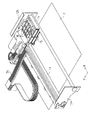
図1は液体噴射装置としてのインクジェット式プリンタ10(以下、単にプリンタ10という。)を示す斜視図、図2はプリンタ10内部を示す要部斜視図である。図1に示すように、プリンタ10には、本体ケース11が備えられている。
図3及び図4は、そのカートリッジ18の外観形状を示す斜視図であり、図5は、そのカートリッジ18の内部を示す断面図である。図3〜図5に示すように、カートリッジ18は、カートリッジケース19とインクパック20とを備えている。
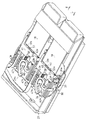
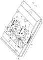
図6はカートリッジホルダ17の一部にカートリッジ18を装着した状態を示す平面図、図7および図8はそれぞれカートリッジ18を装着した状態およびカートリッジ18を装着していない状態のカートリッジホルダ17を示す斜視図である。また、図9はカートリッジホルダ17の内部を示す斜視図である。
次に、上記のように構成したカートリッジホルダ17の作用について説明する。まず、差込位置にあるスライダ40にカートリッジ18を装着する操作について説明する。
まず、加圧ポンプ26を停止してカートリッジ18内への大気の圧送を停止する。続いて、固定手段36によって使用位置に位置決めされるスライダ40を、再びコイルばねSPの弾性力に抗して差込方向L側に移動する。すると、前記突起36aと係止部21との係合が解除され、スライダ40が、コイルばねSPの弾性力にしたがって、カートリッジ18を装着した状態で抜出方向R側に復動し、差込位置まで移動させる。
(1)本実施形態によれば、スライダ40内の収容空間40aに第1インク吸収体50を収容し、その当接面51aが装着面40cから突出するように配設した。さらに、カートリッジ18がスライダ40に装着される間、その第1インク吸収体50の当接面51aが、差込面19bに当接して、差込口23を第1インク吸収体50で覆うようにした。しかも、差込位置にあるスライダ40が、その第1インク吸収体50(挿入孔51b)にてインク供給針32の導入孔32aを収容するようにした。
・上記実施形態では、第1インク吸収体50を収容空間40a内に収容したが、これに限らず、装着面40cに設けてもよく、さらにはカートリッジ18の差込面19bに設けてもよい。
Claims (8)
- 液体を収容する液体収容体の差込口に差し込まれて前記液体収容体の収容する液体を導出可能にする液体導出管を、前記液体収容体の差込口に対して抜き差し可能に取り付ける液体導出管取り付け構造において、
前記液体収容体が装着される装着面を有するとともに、前記装着される液体収容体の差込口に前記液体導出管を差し込む差込位置と、前記装着される液体収容体の液体が使用される使用位置との間を往復動するスライダを備え、
前記スライダの前記装着面には第1吸収体が設けられ、
前記第1吸収体は、前記スライダが前記差込位置に配置された状態で、前記差込口の形成された前記液体収容体の面に当接し、且つ、前記差込口の前記液体導出管側を覆うように、前記装着面から突出している
ことを特徴とする液体導出管取り付け構造。 - 請求項1に記載する液体導出管取り付け構造において、
前記第1吸収体は、
前記液体収容体の差込口が形成される面に設けられる
ことを特徴とする液体導出管取り付け構造。 - 請求項1または2に記載する液体導出管取り付け構造において、
前記液体収容体と前記液体導出管とを収容する収容部から離間する位置に、前記第1吸収体の吸収した液体の一部を吸収する第2吸収体を設けた
ことを特徴とする液体導出管取り付け構造。 - 請求項3に記載する液体導出管取り付け構造において、
前記第1吸収体は、前記第2吸収体と接触する接触片を有した多孔質部材であって、
前記第2吸収体は、前記接触片を介して前記第1吸収体の吸収した液体の一部を吸収する多孔質部材である
ことを特徴とする液体導出管取り付け構造。 - 請求項3または4に記載する液体導出管取り付け構造において、
前記第1吸収体は、その容積に相対する容量の液体を吸収する多孔質部材であって、
前記第2吸収体は、前記第1吸収体よりも大きい容量の液体を吸収する多孔質部材である
ことを特徴とする液体導出管取り付け構造。 - 請求項1〜5のいずれか1つに記載する液体導出管取り付け構造において、
前記第1吸収体は、前記液体導出管の外周を覆う
ことを特徴とする液体導出管取り付け構造。 - 請求項1〜6のいずれか1つに記載する液体導出管取り付け構造において、
前記液体収容体は、加圧手段の圧送する大気の加圧によって収容する液体を前記差込口から導出可能にする
ことを特徴とする液体導出管取り付け構造。 - ターゲットに対して液体を噴射する液体噴射ヘッドに液体導出管を通じて液体収容体の収容する液体を供給する液体噴射装置において、
前記液体導出管は、請求項1〜7のいずれか1つに記載する液体導出管取り付け構造を備えた
ことを特徴とする液体噴射装置。
Priority Applications (1)
| Application Number | Priority Date | Filing Date | Title |
|---|---|---|---|
| JP2012062718A JP5212560B2 (ja) | 2012-03-19 | 2012-03-19 | 液体導出管取り付け構造及び液体噴射装置 |
Applications Claiming Priority (1)
| Application Number | Priority Date | Filing Date | Title |
|---|---|---|---|
| JP2012062718A JP5212560B2 (ja) | 2012-03-19 | 2012-03-19 | 液体導出管取り付け構造及び液体噴射装置 |
Related Parent Applications (1)
| Application Number | Title | Priority Date | Filing Date |
|---|---|---|---|
| JP2010058489A Division JP5018916B2 (ja) | 2010-03-15 | 2010-03-15 | 液体導出管取り付け構造及び液体噴射装置 |
Related Child Applications (1)
| Application Number | Title | Priority Date | Filing Date |
|---|---|---|---|
| JP2012152200A Division JP5212565B2 (ja) | 2012-07-06 | 2012-07-06 | 液体導出管取り付け構造及び液体噴射装置 |
Publications (2)
| Publication Number | Publication Date |
|---|---|
| JP2012111240A true JP2012111240A (ja) | 2012-06-14 |
| JP5212560B2 JP5212560B2 (ja) | 2013-06-19 |
Family
ID=46495956
Family Applications (1)
| Application Number | Title | Priority Date | Filing Date |
|---|---|---|---|
| JP2012062718A Expired - Fee Related JP5212560B2 (ja) | 2012-03-19 | 2012-03-19 | 液体導出管取り付け構造及び液体噴射装置 |
Country Status (1)
| Country | Link |
|---|---|
| JP (1) | JP5212560B2 (ja) |
Cited By (1)
| Publication number | Priority date | Publication date | Assignee | Title |
|---|---|---|---|---|
| US11529811B2 (en) | 2019-12-05 | 2022-12-20 | Seiko Epson Corporation | Liquid ejecting apparatus |
Citations (9)
| Publication number | Priority date | Publication date | Assignee | Title |
|---|---|---|---|---|
| JPH03108557A (ja) * | 1989-09-22 | 1991-05-08 | Canon Inc | インクジェット記録装置 |
| JPH04141444A (ja) * | 1990-10-03 | 1992-05-14 | Canon Inc | インクジェット記録装置 |
| JPH054349A (ja) * | 1991-02-04 | 1993-01-14 | Canon Inc | インクカートリツジ及び該カートリツジを装填可能なインクジエツト記録装置 |
| JPH05162323A (ja) * | 1991-12-11 | 1993-06-29 | Canon Inc | インクジェット記録装置 |
| JPH06238908A (ja) * | 1993-02-19 | 1994-08-30 | Sharp Corp | インクカートリッジ及びインクジェット記録装置 |
| JPH0820114A (ja) * | 1994-07-06 | 1996-01-23 | Canon Inc | インクジェット記録装置 |
| JPH0924618A (ja) * | 1995-07-10 | 1997-01-28 | Canon Inc | インクジェット記録装置 |
| JPH1170663A (ja) * | 1997-08-28 | 1999-03-16 | Seiko Epson Corp | インクジェットプリンタのインクカートリッジ挿入機構 |
| JP2002001979A (ja) * | 2000-06-20 | 2002-01-08 | Seiko Epson Corp | 記録装置用インクカートリッジ |
-
2012
- 2012-03-19 JP JP2012062718A patent/JP5212560B2/ja not_active Expired - Fee Related
Patent Citations (9)
| Publication number | Priority date | Publication date | Assignee | Title |
|---|---|---|---|---|
| JPH03108557A (ja) * | 1989-09-22 | 1991-05-08 | Canon Inc | インクジェット記録装置 |
| JPH04141444A (ja) * | 1990-10-03 | 1992-05-14 | Canon Inc | インクジェット記録装置 |
| JPH054349A (ja) * | 1991-02-04 | 1993-01-14 | Canon Inc | インクカートリツジ及び該カートリツジを装填可能なインクジエツト記録装置 |
| JPH05162323A (ja) * | 1991-12-11 | 1993-06-29 | Canon Inc | インクジェット記録装置 |
| JPH06238908A (ja) * | 1993-02-19 | 1994-08-30 | Sharp Corp | インクカートリッジ及びインクジェット記録装置 |
| JPH0820114A (ja) * | 1994-07-06 | 1996-01-23 | Canon Inc | インクジェット記録装置 |
| JPH0924618A (ja) * | 1995-07-10 | 1997-01-28 | Canon Inc | インクジェット記録装置 |
| JPH1170663A (ja) * | 1997-08-28 | 1999-03-16 | Seiko Epson Corp | インクジェットプリンタのインクカートリッジ挿入機構 |
| JP2002001979A (ja) * | 2000-06-20 | 2002-01-08 | Seiko Epson Corp | 記録装置用インクカートリッジ |
Cited By (1)
| Publication number | Priority date | Publication date | Assignee | Title |
|---|---|---|---|---|
| US11529811B2 (en) | 2019-12-05 | 2022-12-20 | Seiko Epson Corporation | Liquid ejecting apparatus |
Also Published As
| Publication number | Publication date |
|---|---|
| JP5212560B2 (ja) | 2013-06-19 |
Similar Documents
| Publication | Publication Date | Title |
|---|---|---|
| KR102125817B1 (ko) | 액체 토출 장치 및 헤드 | |
| KR100936839B1 (ko) | 액체 수납 용기 및 액체 공급 장치 | |
| JP4561395B2 (ja) | アタッチメント及び液体供給装置 | |
| KR20170051319A (ko) | 액체 토출 장치 및 헤드 | |
| JPH11170559A (ja) | インクジェットカートリッジ | |
| EP1790478B1 (en) | Liquid ejecting apparatus | |
| JP5018941B2 (ja) | 液体導出管取り付け構造及び液体噴射装置 | |
| JP5018916B2 (ja) | 液体導出管取り付け構造及び液体噴射装置 | |
| JP4556540B2 (ja) | 液体導出管取り付け構造及び液体噴射装置 | |
| JP4973764B2 (ja) | 液体供給装置 | |
| JP5212560B2 (ja) | 液体導出管取り付け構造及び液体噴射装置 | |
| JP5212565B2 (ja) | 液体導出管取り付け構造及び液体噴射装置 | |
| JP2006082294A (ja) | 液体収容体の収納容器及び液体噴射装置 | |
| US8567902B2 (en) | Waste liquid recovery apparatus and liquid ejecting apparatus | |
| JP2006021451A (ja) | 液体吸収体、液体回収ユニットおよび液体噴射装置 | |
| JP2005297286A (ja) | 液体収容体収納容器及び液体噴射装置 | |
| JP4590996B2 (ja) | 液体収容体の収納容器及び液体噴射装置 | |
| JP2007160795A (ja) | 液体噴射付属装置 | |
| JP2006082293A (ja) | 液体噴射装置 | |
| JP2005343123A (ja) | 減圧弁、キャリッジおよび液体噴射装置 | |
| JP4251212B2 (ja) | 液体収容部及び液体噴射装置 | |
| JP5842605B2 (ja) | リフィルケース | |
| JP5532161B2 (ja) | 液体供給装置及び液体カートリッジ | |
| CN100542819C (zh) | 墨盒和喷墨打印机 | |
| JP2006082292A (ja) | 液体収容体の収納容器及び液体噴射装置 |
Legal Events
| Date | Code | Title | Description |
|---|---|---|---|
| RD04 | Notification of resignation of power of attorney |
Free format text: JAPANESE INTERMEDIATE CODE: A7424 Effective date: 20120417 |
|
| A521 | Written amendment |
Free format text: JAPANESE INTERMEDIATE CODE: A523 Effective date: 20120418 |
|
| A621 | Written request for application examination |
Free format text: JAPANESE INTERMEDIATE CODE: A621 Effective date: 20120418 |
|
| RD03 | Notification of appointment of power of attorney |
Free format text: JAPANESE INTERMEDIATE CODE: A7423 Effective date: 20120418 |
|
| A131 | Notification of reasons for refusal |
Free format text: JAPANESE INTERMEDIATE CODE: A131 Effective date: 20120522 |
|
| A521 | Written amendment |
Free format text: JAPANESE INTERMEDIATE CODE: A523 Effective date: 20120720 |
|
| A131 | Notification of reasons for refusal |
Free format text: JAPANESE INTERMEDIATE CODE: A131 Effective date: 20120820 |
|
| A521 | Written amendment |
Free format text: JAPANESE INTERMEDIATE CODE: A523 Effective date: 20121010 |
|
| A131 | Notification of reasons for refusal |
Free format text: JAPANESE INTERMEDIATE CODE: A131 Effective date: 20121106 |
|
| A521 | Written amendment |
Free format text: JAPANESE INTERMEDIATE CODE: A523 Effective date: 20121228 |
|
| TRDD | Decision of grant or rejection written | ||
| A01 | Written decision to grant a patent or to grant a registration (utility model) |
Free format text: JAPANESE INTERMEDIATE CODE: A01 Effective date: 20130129 |
|
| A61 | First payment of annual fees (during grant procedure) |
Free format text: JAPANESE INTERMEDIATE CODE: A61 Effective date: 20130211 |
|
| R150 | Certificate of patent or registration of utility model |
Ref document number: 5212560 Country of ref document: JP Free format text: JAPANESE INTERMEDIATE CODE: R150 Free format text: JAPANESE INTERMEDIATE CODE: R150 |
|
| FPAY | Renewal fee payment (event date is renewal date of database) |
Free format text: PAYMENT UNTIL: 20160308 Year of fee payment: 3 |
|
| S531 | Written request for registration of change of domicile |
Free format text: JAPANESE INTERMEDIATE CODE: R313531 |
|
| R350 | Written notification of registration of transfer |
Free format text: JAPANESE INTERMEDIATE CODE: R350 |
|
| LAPS | Cancellation because of no payment of annual fees |