JP2012111422A - Azimuth propeller and ship provided with the same - Google Patents
Azimuth propeller and ship provided with the same Download PDFInfo
- Publication number
- JP2012111422A JP2012111422A JP2010263842A JP2010263842A JP2012111422A JP 2012111422 A JP2012111422 A JP 2012111422A JP 2010263842 A JP2010263842 A JP 2010263842A JP 2010263842 A JP2010263842 A JP 2010263842A JP 2012111422 A JP2012111422 A JP 2012111422A
- Authority
- JP
- Japan
- Prior art keywords
- rudder plate
- rudder
- plate
- azimuth
- propeller
- Prior art date
- Legal status (The legal status is an assumption and is not a legal conclusion. Google has not performed a legal analysis and makes no representation as to the accuracy of the status listed.)
- Withdrawn
Links
- 238000011144 upstream manufacturing Methods 0.000 claims abstract description 26
- XLYOFNOQVPJJNP-UHFFFAOYSA-N water Substances O XLYOFNOQVPJJNP-UHFFFAOYSA-N 0.000 claims description 66
- 238000000034 method Methods 0.000 description 10
- 230000000694 effects Effects 0.000 description 5
- 238000010586 diagram Methods 0.000 description 4
- 238000005452 bending Methods 0.000 description 2
- 230000002452 interceptive effect Effects 0.000 description 2
- 101100491335 Caenorhabditis elegans mat-2 gene Proteins 0.000 description 1
- 230000001141 propulsive effect Effects 0.000 description 1
Images

Classifications
-
- B—PERFORMING OPERATIONS; TRANSPORTING
- B63—SHIPS OR OTHER WATERBORNE VESSELS; RELATED EQUIPMENT
- B63H—MARINE PROPULSION OR STEERING
- B63H25/00—Steering; Slowing-down otherwise than by use of propulsive elements; Dynamic anchoring, i.e. positioning vessels by means of main or auxiliary propulsive elements
- B63H25/42—Steering or dynamic anchoring by propulsive elements; Steering or dynamic anchoring by propellers used therefor only; Steering or dynamic anchoring by rudders carrying propellers
-
- B—PERFORMING OPERATIONS; TRANSPORTING
- B63—SHIPS OR OTHER WATERBORNE VESSELS; RELATED EQUIPMENT
- B63H—MARINE PROPULSION OR STEERING
- B63H25/00—Steering; Slowing-down otherwise than by use of propulsive elements; Dynamic anchoring, i.e. positioning vessels by means of main or auxiliary propulsive elements
- B63H25/44—Steering or slowing-down by extensible flaps or the like
-
- B—PERFORMING OPERATIONS; TRANSPORTING
- B63—SHIPS OR OTHER WATERBORNE VESSELS; RELATED EQUIPMENT
- B63H—MARINE PROPULSION OR STEERING
- B63H5/00—Arrangements on vessels of propulsion elements directly acting on water
- B63H5/07—Arrangements on vessels of propulsion elements directly acting on water of propellers
- B63H5/125—Arrangements on vessels of propulsion elements directly acting on water of propellers movably mounted with respect to hull, e.g. adjustable in direction, e.g. podded azimuthing thrusters
-
- B—PERFORMING OPERATIONS; TRANSPORTING
- B63—SHIPS OR OTHER WATERBORNE VESSELS; RELATED EQUIPMENT
- B63H—MARINE PROPULSION OR STEERING
- B63H5/00—Arrangements on vessels of propulsion elements directly acting on water
- B63H5/07—Arrangements on vessels of propulsion elements directly acting on water of propellers
- B63H5/125—Arrangements on vessels of propulsion elements directly acting on water of propellers movably mounted with respect to hull, e.g. adjustable in direction, e.g. podded azimuthing thrusters
- B63H2005/1254—Podded azimuthing thrusters, i.e. podded thruster units arranged inboard for rotation about vertical axis
Landscapes
- Chemical & Material Sciences (AREA)
- Engineering & Computer Science (AREA)
- Combustion & Propulsion (AREA)
- Mechanical Engineering (AREA)
- Ocean & Marine Engineering (AREA)
- Vibration Prevention Devices (AREA)
- Prevention Of Electric Corrosion (AREA)
- Toys (AREA)
Abstract
Description
本発明は、ポッドと一体化した舵板を有するアジマス推進器に関する。 The present invention relates to an azimuth thruster having a rudder plate integrated with a pod.
従来、船舶を任意の方向に移動させたり、現在位置を正確に維持することができるアジマス推進器としては、図6に示すように、ポッド2と、プロペラ3と、舵板4とが船舶Sの船尾等に取り付けられている。
Conventionally, as an azimuth propulsion device that can move a ship in an arbitrary direction or accurately maintain the current position, as shown in FIG. 6, a
この場合の舵板4は、水平断面を舵形状とし、船舶Sとの連結軸部を含む上部舵板4aと、ポッド2の下方へ延在して同様の舵断面形状を有する下部舵板4bとにより構成されている。舵板4及びプロペラ3を備えたポッド2は、船舶Sに対して一体に回動可能となっている。
また、船舶Sの船内には、原動機5が設置されており、原動機5の動力は、ポッド2内に設けられている2組の傘歯車ユニット6、7を介してプロペラ3に伝達される。
In this case, the
In addition, a
このようなアジマス推進器1は、舵板4を船体S内に設置された図示しない旋回装置によって旋回させることにより、船舶Sの航行方向を変える舵の役目も兼ねており、180°旋回させることにより、船舶Sを後進方向に航行させることができる。
Such an
短時間で船舶Sを旋回させるためにアジマス推進器1を大きな舵角で旋回させた場合には、図6の紙面右側から左側に向かう矢印に示すように流れる水流が舵板4の下流側(船尾側)に設けられているプロペラ3に作用する。
When the
このプロペラ3に作用する水流は、舵角と同じ大きな角度でプロペラ3に作用する。そのため、プロペラ3は、舵角と同じ大きな角度の斜流中を旋回することになりプロペラ3から発生する力の変動が大きくなる。プロペラ3が生じる大きな力の変動は、アジマス推進器1全体を振動させることとなり、この振動が船舶Sの船体や関連機器(図示せず)にまで伝播して故障の原因となる。
The water flow acting on the
このようにアジマス推進器に作用する力の変動を抑制するために、特許文献1にはプロペラの下流側の舵板に、舵板の長辺と略同等の長さを有するフラップを設けることが開示されている。また、特許文献2には、舵板の形状を予め非対称に形成することが開示されている。
Thus, in order to suppress the fluctuation | variation of the force which acts on an azimuth propelling device, in
特許文献3には、1つのポッドを2枚の舵板の間に挟むように設けて、船速に応じて舵角を切り替えることが開示されている。
しかし、近年では、更に一層アジマス推進器の舵角を小さくして、かつ、アジマス推進器に生じる振動を抑制することが望まれている。
また、特許文献3に開示されている発明は船速に応じて舵角を切換える方法であり、実際の航行時には、船速に関わらずアジマス推進器の舵角を小さくすることが望まれている。
However, in recent years, it has been desired to further reduce the rudder angle of the azimuth thruster and suppress the vibration generated in the azimuth thruster.
The invention disclosed in
本発明は、上記の事情に鑑みてなされたものであり、旋回時の舵角を小さくして、旋回による振動の発生を抑制することが可能なアジマス推進器およびこれを備えた船舶を提供することにある。 The present invention has been made in view of the above circumstances, and provides an azimuth propulsion device capable of reducing the rudder angle during turning and suppressing the occurrence of vibration due to turning, and a ship equipped with the same. There is.
本発明は、上記の課題を解決するため、下記の手段を採用した。
本発明に係るアジマス推進器によれば、ポッドと一体に設けられ、該ポッドの中心軸線に対して略直交する方向に長軸を有して延在する舵形状の舵板と、前記ポッドの端部に設けられ、前記舵板の上流側に設けられる推進器と、を備え、前記舵板の下流側長辺には、前記舵板の前記長軸方向に複数分割されて互いに独立に動作するフラップが設けられることを特徴とする。
In order to solve the above problems, the present invention employs the following means.
According to the azimuth propelling apparatus according to the present invention, a rudder-shaped rudder plate that is provided integrally with the pod and has a long axis extending in a direction substantially orthogonal to the central axis of the pod, A propulsion device provided at an end portion and provided upstream of the rudder plate, and on the long side on the downstream side of the rudder plate, the plural portions are divided in the major axis direction of the rudder plate and operate independently of each other A flap is provided.
推進器の下流側であり、ポッドと一体に設ける舵形状の舵板を有するアジマス推進器を回転させた際には、推進器によって生じる水流が推進器の後流からポッドおよび舵板の側面へと導かれる。 When rotating an azimuth propulsion unit that is downstream of the propulsion unit and has a rudder-shaped rudder plate that is provided integrally with the pod, the water flow generated by the propulsion unit moves from the wake of the propulsion unit to the side of the pod and the rudder plate. It is guided.
そこで、上流側の端部に推進器を有しているポッドと一体に設けられる舵形状の舵板の下流側長辺に、舵板の長軸方向に複数分割されたフラップを設けることとした。さらに、これら複数のフラップは、各々独立に動作可能とすることとした。これにより、推進器から舵板の側面を経て舵板の下流側長辺へと導かれる推進器の水流方向に応じて、各フラップを動かすことができる。そのため、推進器による水流を妨げることなく各フラップを動作させて、舵抵抗を低減してアジマス推進器を小舵角にて旋回させることができる。また、フラップを各々独立に動作することができるので、水流の流れを大きく変化させたい位置のフラップを大きく動作させることによって舵力を増加させることができる。したがって、アジマス推進器の旋回性能を高めると共に、アジマス推進器を旋回させる際の船体振動や関連機器の振動を抑制することができる。 Therefore, on the downstream long side of the rudder-shaped rudder plate provided integrally with the pod having the propulsion device at the upstream end, it is decided to provide a plurality of flaps divided in the major axis direction of the rudder plate. . Furthermore, the plurality of flaps can be operated independently. Thereby, each flap can be moved according to the water flow direction of the propulsion unit guided from the propulsion unit to the long downstream side of the rudder plate through the side surface of the rudder plate. Therefore, each flap can be operated without interfering with the water flow by the propelling device, and the rudder resistance can be reduced and the azimuth propelling device can be turned at a small rudder angle. Further, since the flaps can be operated independently, the rudder force can be increased by operating the flaps at positions where it is desired to greatly change the flow of the water flow. Therefore, the turning performance of the azimuth propelling device can be improved, and the hull vibration and the vibration of related equipment when turning the azimuth propelling device can be suppressed.
本発明に係るアジマス推進器によれば、前記舵板の上流側長辺には、フラップを設けることを特徴とする。 The azimuth propelling apparatus according to the present invention is characterized in that a flap is provided on the upstream long side of the rudder plate.
舵板の上流側に設けられる推進器を端部に有するポッドと一体に設けられる舵形状の舵板には、舵板の上流側長辺にフラップを設けることとした。これにより、推進器が回動する際に生じる水流およびアジマス推進器が旋回する際に生じる旋回流をフラップによって整流して、ポッドおよび舵板の側面へと導くことができる。そのため、舵抵抗を低減して、アジマス推進器を小舵角にて旋回させることができる。したがって、アジマス推進器の旋回性能を高めることができる。 In the rudder-shaped rudder plate provided integrally with the pod having the propeller provided at the upstream side of the rudder plate, a flap is provided on the upstream long side of the rudder plate. Thereby, the water flow generated when the propulsion device rotates and the swirl flow generated when the azimuth propelling device turns can be rectified by the flap and guided to the side surfaces of the pod and the steering plate. Therefore, rudder resistance can be reduced and the azimuth propelling device can be turned at a small rudder angle. Therefore, the turning performance of the azimuth propelling device can be improved.
本発明に係るアジマス推進器によれば、前記フラップは、前記舵板の前記長軸方向に複数分割されて互いに独立に動作することを特徴とする。 According to the azimuth propelling apparatus of the present invention, the flap is divided into a plurality of pieces in the major axis direction of the rudder plate and operates independently of each other.
舵板の上流側長辺には、舵板の長軸方向に複数分割されたフラップを設け、各フラップを各々独立に動作することとした。そのため、推進器が生じる水流方向に応じて合わせてフラップを動かして整流することができる。したがって、急激な水流の変化を少なくすることができ、舵板への負荷や振動の発生を抑制することができる。 The upstream long side of the rudder plate is provided with a plurality of divided flaps in the long axis direction of the rudder plate, and each flap is operated independently. Therefore, the flap can be moved and rectified according to the direction of water flow generated by the propulsion device. Therefore, a rapid change in water flow can be reduced, and the load on the steering plate and the occurrence of vibration can be suppressed.
本発明に係るアジマス推進器によれば、前記舵板の側面には、前記推進器が回転することによって生じる水流方向に沿って前記舵板の上流側長辺から下流側長辺に延在する少なくとも1の整流手段を備えることを特徴とする。 According to the azimuth thruster according to the present invention, the side surface of the rudder plate extends from the upstream long side to the downstream long side of the rudder plate along a water flow direction generated by the rotation of the propulsion unit. It comprises at least one rectifying means.
推進器が回転することによって生じる水流方向に沿って延在する整流手段を舵板の側面に設けることとした。これにより、舵板の側面に導かれた推進器からの水流を整流して舵板の上流側長辺から下流側長辺と導くことができる。そのため、舵板の下流側長辺へ導かれる水流に乱れが生じないため、舵板の下流側長辺に設けたフラップを効果的に動作させることができる。 The rectifying means extending along the direction of water flow generated by the rotation of the propelling device is provided on the side surface of the rudder plate. Thereby, the water flow from the propulsion device guided to the side surface of the rudder plate can be rectified and led from the upstream long side of the rudder plate to the downstream long side. Therefore, the water flow guided to the downstream long side of the rudder plate is not disturbed, and the flaps provided on the downstream long side of the rudder plate can be operated effectively.
本発明に係るアジマス推進器によれば、前記整流手段は、前記舵板の側面上に回動可能に設けられることを特徴とする。 The azimuth propelling apparatus according to the present invention is characterized in that the rectifying means is rotatably provided on a side surface of the rudder plate.
舵板の側面上に回動可能に整流手段を設けることとした。そのため、潮流の変化や推進器の回転数の変化によって舵板に導かれる水流の変化に合わせて整流手段の延在方向を変えることができる。したがって、複雑な水流に対応することができる。 The rectifying means is provided on the side surface of the rudder so as to be rotatable. Therefore, the extending direction of the rectifying means can be changed in accordance with the change of the water flow guided to the steering plate by the change of the tidal current and the change of the rotation speed of the propulsion device. Therefore, it can cope with a complicated water flow.
本発明に係る船舶によれば、上記のいずれかに記載のアジマス推進器を備えたことを特徴とする。 A ship according to the present invention includes the azimuth propelling apparatus according to any one of the above.
小舵角、かつ、大きな旋回力を得ることができるアジマス推進器を用いることとした。そのため、船舶の旋回能力を高めるとともに、水流の変化を起因とする振動を低減した船舶にすることができる。 We decided to use an azimuth propelling device capable of obtaining a small turning angle and a large turning force. Therefore, while improving the turning capability of a ship, it can be set as the ship which reduced the vibration resulting from the change of a water flow.
上述した本発明のアジマス推進器によれば、舵板の上流側の端部に推進器を有しているポッドと一体に設けられている舵形状の舵板の下流側長辺に、舵板の長軸方向に複数分割されたフラップを設けることとした。さらに、これら複数のフラップは、各々独立に動作可能とすることとした。これにより、推進器から舵板の側面を経て舵板の下流側長辺へと導かれる推進器の水流方向に応じて、各フラップを動かすことができる。そのため、推進器による水流を妨げることなく各フラップを動作させて、舵抵抗を低減してアジマス推進器を小舵角にて旋回させることができる。また、フラップを各々独立に動作することができるので、水流の流れを大きく変化させたい位置のフラップを大きく動作させることによって舵力を増加させることができる。したがって、アジマス推進器の旋回性能を高めると共に、アジマス推進器を旋回させる際の船体振動や関連機器の振動を抑制することができる。 According to the azimuth propelling device of the present invention described above, the rudder plate is disposed on the long downstream side of the rudder-shaped rudder plate provided integrally with the pod having the propulsion unit at the upstream end of the rudder plate. A plurality of divided flaps are provided in the major axis direction. Furthermore, the plurality of flaps can be operated independently. Thereby, each flap can be moved according to the water flow direction of the propulsion unit guided from the propulsion unit to the long downstream side of the rudder plate through the side surface of the rudder plate. Therefore, each flap can be operated without interfering with the water flow by the propelling device, and the rudder resistance can be reduced and the azimuth propelling device can be turned at a small rudder angle. Further, since the flaps can be operated independently, the rudder force can be increased by operating the flaps at positions where it is desired to greatly change the flow of the water flow. Therefore, the turning performance of the azimuth propelling device can be improved, and the hull vibration and the vibration of related equipment when turning the azimuth propelling device can be suppressed.
[第1実施形態]
以下、本発明に係る船舶に設けられているアジマス推進器について図1に基づいて説明する。
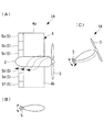
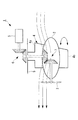
図1は、舶用推進装置の一例として、アジマス推進器の概略構成例を示している。図示のアジマス推進器1Aは、船舶(図示せず)の船尾等に取り付けて使用される舶用推進装置の一種である。このアジマス推進器1Aは、船舶の船内に設置した動力源(図示せず)の動力を機械的に伝達し、舵形状にした舵板4を介して船体に取り付けられたポッド2のプロペラ(推進器)3を駆動して推進力を得る装置である。さらに、このアジマス推進器1Aは、船舶に対して、舵として機能する舵板4と一体にポッド2が旋回することにより、船舶の推進(航行)方向を変化させることができる。
[First Embodiment]
Hereinafter, the azimuth propelling apparatus provided in the ship which concerns on this invention is demonstrated based on FIG.
FIG. 1 shows a schematic configuration example of an azimuth propelling device as an example of a marine propulsion device. The illustrated
舵板4は、ポッド2と一体に設けられてポッド2の中心軸線に対して略直交する方向に長軸を有して延在している。舵板4は、水平断面を舵形状とする領域を設けたことで舵を兼ねている。すなわち、舵板4は、舵形状の水平断面を有し、船舶との連結軸部を含む上部舵板4aと、ポッド2の下方へ延在して同様の舵断面形状を有する下部舵板4bとにより構成されている。舵板4及びプロペラ3を備えたポッド2は、図示しない旋回装置により、船舶に対して一体に旋回するようになっている。
The
舵板4の船尾側(下流側、図1において左側)の長辺(下流側長辺)には、舵板4の長軸方向に複数に分割されているフラップ5が設けられている。複数のフラップ5は、舵板4の船尾側の一辺に渡って設けられており、例えば6分割されている。各フラップ5a、5b、5c、5d、5e、5fは、例えば、ヒンジ(図示せず)などによって舵板4の船尾側の一辺に固定されている。複数のフラップ5a、5b、5c、5d、5e、5fは、各々が独立に動作可能とされている。
On the stern side (downstream side, left side in FIG. 1) of the
ポッド2は、略繭形状をしている。ポッド2は、上部舵板4aと下部舵板4bとの間にポッド2の長軸が舵板4の長軸と略直交するようにして設けられている。
プロペラ3は、ポッド2の船首側(図1において右側)の端部であり、舵板4の上流側に設けられている。
The
The
次に、アジマス推進器1Aを旋回させる際における制御方法について説明する。
船舶の船内に設置した旋回装置によって、プラペラ3が回転駆動しているアジマス推進器1Aを旋回する。その際に、アジマス推進器1Aを構成している舵板4の船尾側に設けられている複数のフラップ5a、5b、5c、5d、5e、5fを各々独立に折り曲げる(動作させる)。
Next, a control method when turning the
The
プロペラ3が回転駆動することによって生じる水流は、図1(A)および図1(C)の矢印で示すように、プロペラ3の後流からボッド2および舵板4の側面に沿って船尾側へと導かれる。
舵板4の船尾側に設けられているフラップ5a、5b、5c、5d、5e、5fを、例えば、紙面手前に折り曲げることにより、舵板4の船尾側に導かれた水流の流れ方向が2段階に変化する。
As shown by the arrows in FIGS. 1 (A) and 1 (C), the water flow generated when the
For example, when the
舵板4の船尾側に導かれた水流の流れ方向を変化させるフラップ5a、5b、5c、5d、5e、5fは、分割されて各々が独立に動作することができる。そのため、例えば、図1(A)に示すように、ポッド2近傍でありポッド2の下方に位置しているフラップ5dを折り曲げてフラップ5dの傾斜角度を大きくし、それ以外のフラップ5a、5b、5c、5e、5fを折り曲げる際にはそれらの傾斜角度をフラップ5dに比べて小さくしたり、または、折り曲げないなどとする。
The
このように、舵板4の船尾側の一辺に設けられている複数のフラップ5a、5b、5c、5d、5e、5fを各々独立に折り曲げることによって、プロペラ3の回転により生じた水流を妨げることなく水流の流れ方向を大きく変化させることができる。
In this way, the plurality of
そのため、アジマス推進器1Aを旋回させる際に、各フラップ5a、5b、5c、5d、5e、5fを互いに独立に折り曲げて、舵板4の船尾側に導かれる水流の流れ方向を変化させることによって、急激な水流の変化を生じることなくアジマス推進器1Aを旋回させることができる。したがって、舵板4に作用する負荷や、水流の急激な変化を起因として生じる振動を抑制することができる。
Therefore, when turning the
以上説明したように、本実施形態にかかるアジマス推進機1Aおよびこれを備えた船舶によれば、以下の作用効果を奏する。
舵板4の船首側(上流側)の端部にプロペラ(推進器)3を有しているポッド2と一体に設けられている舵形状の舵板4の船尾側の長辺(下流側長辺)に舵板4の長軸方向に6分割(複数分割)されたフラップ5a、5b、5c、5d、5e、5fを設けることとした。さらに、これらフラップ5a、5b、5c、5d、5e、5fは、各々独立に動作可能とすることとした。これにより、プロペラ3から舵板4の側面を経て舵板4の船尾側の長辺へと導かれるプロペラ3の水流方向に応じて、各フラップ5a、5b、5c、5d、5e、5fを動かすことができる。そのため、プロペラ3による水流を妨げることなく各フラップ5a、5b、5c、5d、5e、5fを折り曲げて(動作させて)、舵抵抗を低減してアジマス推進器1Aを小舵角にて旋回させることができる。また、フラップ5a、5b、5c、5d、5e、5fを各々独立に動作することができるので、水流の流れを大きく変化させたい位置のフラップ5dを大きく折り曲げることによって舵力を増加させることができる。したがって、アジマス推進器1Aの旋回性能を高めると共に、アジマス推進器1Aを旋回させる際の船体振動や関連機器の振動を抑制することができる。
As described above, according to the
The long side (downstream side length) on the stern side of the rudder-shaped
小舵角、かつ、大きな旋回力を得ることができるアジマス推進器1Aを用いることとした。そのため、船舶の旋回能力を高めるとともに、水流の変化を起因とする振動を低減した船舶にすることができる。
The
なお、各フラップ5a、5b、5c、5d、5e、5fを折り曲げる角度は、予め実験などから求められた基礎データに基づいて決定しても良く、また、船舶の航行中に取得しても良い。さらに、航行中に初期のデータを適宜補正しても良い。
Note that the angle at which the
[第2実施形態]
本実施形態のアジマス推進器およびこれを備えた船舶は、舵板の船首側にフラップを設ける点で、第1実施形態と相違しその他は同様である。したがって、同一の構成および制御方法については、同一の符号を付してその説明を省略する。
[Second Embodiment]
The azimuth propelling apparatus of this embodiment and a ship equipped with the same are different from the first embodiment in that a flap is provided on the bow side of the rudder plate, and the others are the same. Therefore, about the same structure and control method, the same code | symbol is attached | subjected and the description is abbreviate | omitted.
図2には、本実施形態のアジマス推進器1Bの概略構成例が示されている。
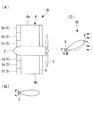
本実施形態のアジマス推進器1Bは、舵板4の船尾側に6分割されたフラップ5a、5b、5c、5d、5e、5fが設けられると共に、舵板4の船首側(上流側、図2において右側)であってプロペラ(推進器)3の後流近傍の長辺(上流側長辺)に1つのフラップ6が設けられている。
FIG. 2 shows a schematic configuration example of the
The
フラップ6は、舵板4の船首側の一辺に渡って設けられている。フラップ6は、例えば、ヒンジ(図示せず)などによって舵板4の船首側の一辺に固定されている。
The
次に、アジマス推進器1Bを旋回させる際における制御方法について説明する。
船舶の船内(図示せず)に設置した旋回装置(図示せず)によって、プラペラ3が回転駆動しているアジマス推進器1Bを旋回する。その際に、アジマス推進器1Bを構成している舵板4の船首側に設けられているフラップ6を折り曲げる(動作させる)。また、舵板4の船尾側に設けられている複数のフラップ5a、5b、5c、5d、5e、5fを各々独立に折り曲げる。
Next, a control method when turning the
The
プロペラ3が回転駆動することによって生じる水流、および、アジマス推進器1Bが旋回することにより生じる旋回流は、図2(A)および図2(C)の矢印で示すように、プロペラ3の後流からフラップ6に導かれる。舵板4の船首側に設けられているフラップ6を、図2(C)に示すように、例えば紙面手前に折り曲げることにより、舵板4の船首側に導かれたプロペラ3による水流、および、アジマス推進器1Bが旋回することにより生じる旋回流の流れ方向が変化する。
The water flow generated by the rotation of the
フラップ6によって流れ方向が変えられたプロペラ3による水流およびアジマス推進器1Bの旋回流は、ボッド2および舵板4の側面に沿って船尾側へと導かれる。舵板4の船尾側に導かれた水流および旋回流は、舵板4の船尾側に設けられているフラップ5a、5b、5c、5d、5e、5fを、例えば、紙面手前に折り曲げることにより、図2(C)の矢印で示すように、流れ方向が3段階に変化する。
The water flow by the
このように、舵板4の船首側の一辺にフラップ6の傾斜角度を調整することによって、プロペラ3が生じる水流およびアジマス推進器1Bを旋回させた際に生じる旋回流を整流することができる。そのため、アジマス推進器1Bの舵板4の揚力を向上させて旋回することができる。したがって、小舵角で船舶を旋回させることができる。
Thus, by adjusting the inclination angle of the
以上説明したように、本実施形態にかかるアジマス推進機1Bおよびこれを備えた船舶によれば、以下の作用効果を奏する。
舵板4の船首側(上流側)に設けられているプロペラ(推進器)3を端部に有しているポッド2と一体に設けられている舵形状の舵板4には、舵板4の船首側の長辺(上流側長辺)にフラップ6を設けることとした。これにより、プロペラ3が回動する際に生じる水流およびアジマス推進器1Bが旋回する際に生じる旋回流をフラップ6によって整流して、ポッド2および舵板4の側面へと導くことができる。そのため、舵抵抗を低減して、アジマス推進器1Bを小舵角にて旋回させることができる。したがって、アジマス推進器1Bの旋回性能を高めることができる。
As described above, according to the
The rudder-shaped
なお、本実施形態では、舵板4の船首側の長辺にフラップ6を設けるとして説明したが、本発明は、これに限定されるものではなく、フラップ6の代わりに整流板であっても良い。
In the present embodiment, the
また、フラップ6を折り曲げる角度は、予め実験などから求められた基礎データに基づいて決定しても良く、また、船舶の航行中に取得しても良い。さらに、航行中に初期のデータを適宜補正しても良い。
Moreover, the angle at which the
[第3実施形態]
本実施形態のアジマス推進器およびこれを備えた船舶は、舵板の船首側に複数のフラップを設ける点で、第2実施形態と相違しその他は同様である。したがって、同一の構成および制御方法については、同一の符号を付してその説明を省略する。
[Third Embodiment]
The azimuth propelling apparatus of this embodiment and a ship equipped with the same are different from those of the second embodiment in that a plurality of flaps are provided on the bow side of the rudder plate, and the others are the same. Therefore, about the same structure and control method, the same code | symbol is attached | subjected and the description is abbreviate | omitted.
図3には、本実施形態のアジマス推進器1Cの概略構成例が示されている。
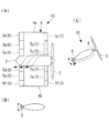
本実施形態のアジマス推進器1Cは、舵板4の船尾側に6分割されたフラップ5a、5b、5c、5d、5e、5fが設けられると共に、舵板4の船首側(上流側、図3において右側)であってプロペラ(推進器)3の後流近傍の長辺(上流側長辺)に舵板4の長軸方向に複数に分割(例えば、6分割)されているフラップ7が設けられている。
FIG. 3 shows a schematic configuration example of the
The
複数のフラップ7は、舵板4の船首側の一辺に渡って設けられており、舵板4の長軸方向に6分割されている。各フラップ7a、7b、7c、7d、7e、7fは、例えば、ヒンジ(図示せず)などによって舵板4の船首側の一辺に固定されている。複数のフラップ7a、7b、7c、7d、7e、7fは、各々が独立に動作可能とされている。
The plurality of
次に、アジマス推進器1Cを旋回させる際における制御方法について説明する。
船舶の船内(図示せず)に設置した旋回装置(図示せず)によって、プラペラ3が回転駆動しているアジマス推進器1Cを旋回する。その際に、アジマス推進器1Cを構成している舵板4の船首側に設けられているフラップ7a、7b、7c、7d、7e、7fを各々独立に折り曲げる(動作させる)。また、舵板4の船尾側に設けられている複数のフラップ5a、5b、5c、5d、5e、5fを各々独立に折り曲げる。
Next, a control method when turning the
The
プロペラ3が回転駆動することによって生じる水流、および、アジマス推進器1Cが旋回することにより生じる旋回流は、図3(A)および図3(C)の矢印で示すように、プロペラ3の後流からフラップ7に導かれる。ここで、フラップ7a、7b、7c、7d、7e、7fは、分割されて各々が独立に動作することができる。そのため、舵板4の船首側に設けられている複数のフラップ7のうちポッド2近傍でありポッド2の下方に位置しているフラップ7dを折り曲げてフラップ7dの傾斜角度を大きくし、それ以外のフラップ7a、7b、7c、7e、7fを折り曲げる際にはそれらの傾斜角度をフラップ7dに比べて小さくしたり、または、折り曲げないなどとする。
The water flow generated by rotating the
このように、舵板4の船首側の一辺に設けた複数のフラップ7a、7b、7c、7d、7e、7fを各々独立に動作させることによって、プロペラ3の回転により生じた水流を妨げることなく水流の流れ方向を大きく変化させることができる。
In this way, by independently operating the plurality of
そのため、アジマス推進器1Cを旋回させる際に、各フラップ7a、7b、7c、7d、7e、7fを独立に折り曲げて、舵板4の船首側から舵板4の側面に導かれる水流の流れを変化させることによって、急激な水流の変化を生じることなくアジマス推進器1Cを旋回させることができる。したがって、舵板4に作用する負荷や、水流の急激な変化を起因として生じる振動を抑制することができる。
Therefore, when turning the
以上説明したように、本実施形態にかかるアジマス推進機1Cおよびこれを備えた船舶によれば、以下の作用効果を奏する。
舵板4の船首側の長辺(上流側長辺)には、舵板4の長軸方向に6分割(複数分割)されたフラップ7a、7b、7c、7d、7e、7fを設け、各フラップ7a、7b、7c、7d、7e、7fを各々独立に折り曲げる(動作する)こととした。そのため、プロペラ(推進器)3が生じる水流方向に応じて合わせてフラップ7a、7b、7c、7d、7e、7fを動かして整流することができる。したがって、急激な水流の変化を少なくすることができ、舵板4への負荷や振動の発生を抑制することができる。
As described above, according to the
On the long side (upstream long side) on the bow side of the
なお、各フラップ7a、7b、7c、7d、7e、7fを折り曲げる角度は、予め実験などから求められた基礎データに基づいて決定しても良く、また、船舶の航行中に取得しても良い。さらに、航行中に初期のデータを適宜補正しても良い。
Note that the angle at which the
[第4実施形態]
本実施形態のアジマス推進器およびこれを備えた船舶は、舵板の側面に溝を設ける点で、第3実施形態と相違しその他は同様である。したがって、同一の構成および制御方法については、同一の符号を付してその説明を省略する。
[Fourth Embodiment]
The azimuth propelling apparatus of this embodiment and a ship equipped with the same are different from the third embodiment in that a groove is provided on the side surface of the rudder plate, and the others are the same. Therefore, about the same structure and control method, the same code | symbol is attached | subjected and the description is abbreviate | omitted.
図4には、本実施形態のアジマス推進器1Dの概略構成例が示されている。
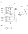
本実施形態のアジマス推進器1Dは、舵板4の側面にプロペラ(推進器)3が回転することによって生じる水流方向に沿って舵板4の船首側の長辺(上流側長辺)から船尾側の長辺(下流側長辺)に延在している、例えば、4つ(少なくとも1)の整流板(整流手段)8を備えている。
FIG. 4 shows a schematic configuration example of the
The
本実施形態の場合には、プロペラの回転方向が船首側(図4の右側)から見た際に時計周りであるとして説明する。
整流板8は、略長方形状であり、本実施形態の場合には、舵板4の船首側から船尾側へと向かって下方に傾斜して4つ設けられている。
In the case of this embodiment, it demonstrates as the rotation direction of a propeller is clockwise when it sees from the bow side (right side of FIG. 4).
The
次に、アジマス推進器1Dを旋回させる際における制御方法について説明する。
船舶の船内(図示せず)に設置した旋回装置(図示せず)によって、プラペラ3が回転駆動しているアジマス推進器1Dを旋回する。その際に、アジマス推進器1Dを構成している舵板4の船首側に設けられているフラップ7a、7b、7c、7d、7e、7fを各々独立に折り曲げる(動作させる)。また、舵板4の船尾側に設けられている複数のフラップ5a、5b、5c、5d、5e、5fを各々独立に折り曲げる。
Next, a control method when turning the
The
プロペラ3が回転駆動することによって生じた水流は、および、アジマス推進器1Dが旋回することにより生じる旋回流は、図4(A)および図4(C)の矢印で示すように、プロペラ3の後流からフラップ7に導かれる。ここで、フラップ7a、7b、7c、7d、7e、7fは、分割されて各々が独立に動作することができる。そのため、舵板4の船首側に設けられている複数のフラップ7のうちポッド2近傍でありポッド2の下方に位置しているフラップ7dを折り曲げて(動作させて)フラップ7dの傾斜角度を大きくし、それ以外のフラップ7a、7b、7c、7e、7fを折り曲げる際にはそれらの傾斜角度をフラップ7dに比べて小さくしたり、または、折り曲げないなどとする。
The water flow generated by the rotation of the
舵板4の船首側に設けた複数のフラップ7a、7b、7c、7d、7e、7fによって流れを方向が変化した水流は、舵板4の側面へと導かれる。舵板4の側面に導かれた水流は、舵板4に設けられている整流板8に沿って流れ方向が整えられて船尾側へと導かれる。
The water flow whose direction has been changed by the plurality of
このように、整流板8によって流れ方向が整えられた水流が舵板4の船尾側に設けられている各フラップ5a、5b、5c、5d、5e、5fに導かれるので、各5a、5b、5c、5d、5e、5fを効果的に折り曲げることができる。
Thus, since the water flow whose flow direction is adjusted by the rectifying
以上説明したように、本実施形態にかかるアジマス推進機1Dおよびこれを備えた船舶によれば、以下の作用効果を奏する。
プロペラ(推進器)3が回転することによって生じる水流方向に沿って延在している整流板(整流手段)8を舵板4の側面に設けることとした。これにより、舵板4の側面に導かれたプロペラからの水流を整流して舵板4の船首側の長辺(上流側長辺)から船尾側の長辺(下流側長辺)と導くことができる。そのため、舵板4の船尾側の長辺へ導かれる水流に乱れが生じないため、舵板4の船尾側の長辺に設けられているフラップ5a、5b、5c、5d、5e、5fを効果的に折り曲げる(動作させる)ことができる。
As described above, the
A rectifying plate (rectifying means) 8 extending along the direction of water flow generated by the rotation of the propeller (propulsion unit) 3 is provided on the side surface of the
なお、本実施形態では、整流手段を整流板8として説明したが、本発明はこれに限定されるものではなく、溝であっても良い。
In the present embodiment, the rectifying means is described as the rectifying
また、本実施形態では、整流板8の傾斜方向を舵板4の船首側から船尾側へ向かって下方に傾斜しているとして説明したが、本発明はこれに限定されるものではなく、プロペラ3の回転によって生じる流れ方向が上下方向に傾斜するように設ければ良い。
Moreover, although this embodiment demonstrated that the inclination direction of the
[第5実施形態]
本実施形態のアジマス推進器およびこれを備えた船舶は、舵板の側面に設けられた整流板が舵板の側面に対して平行に回動する点で、第4実施形態と相違しその他は同様である。したがって、同一の構成および制御方法については、同一の符号を付してその説明を省略する。
[Fifth Embodiment]
The azimuth propelling apparatus of this embodiment and a ship equipped with the same are different from the fourth embodiment in that the rectifying plate provided on the side surface of the steering plate rotates in parallel with the side surface of the steering plate. It is the same. Therefore, about the same structure and control method, the same code | symbol is attached | subjected and the description is abbreviate | omitted.
図5には、本実施形態のアジマス推進器1Eの概略構成例が示されている。
本実施形態のアジマス推進器1Eの舵板4の側面には、舵板4の側面上に回動可能とされている整流板9が設けられている。
FIG. 5 shows a schematic configuration example of the
On the side surface of the
整流板9は、略長方形状であり、本実施形態の場合には、舵板4の船首側(上流側)から船尾側(下流側)へと向かって下方に傾斜して8つ設けられている。これら8つの整流板9は、舵板4の船首側から船尾側へと向かって2列に設けられており、各列には、整流板9が平行に4つ設けられている。
The rectifying
各整流板9は、その長手方向の略中心を回転軸9aが貫通している。回転軸9aは、整流板9を紙面の手前から舵板4の側面に向かって貫通している。これにより、整流板9は、舵板4の側面に対して平行に回転軸9a周りに回動可能となっており、整流板9の延在方向の傾斜角度が可変となっている。このように舵板4の側面に設けられている各整流板9は、各々が互いに独立に回動可能とされている。
Each rectifying
次に、アジマス推進器1Eを旋回させる際における制御方法について説明する。
船舶の船内(図示せず)に設置した旋回装置(図示せず)によって、プラペラ(推進器)3が回転駆動しているアジマス推進器1Eを旋回する。その際に、アジマス推進器1Eを構成している舵板4の船首側の長辺(上流側長辺)に設けられているフラップ7a、7b、7c、7d、7e、7fを各々独立に折り曲げる(動作させる)。また、舵板4の船尾側の長辺(下流側長辺)に設けられている複数のフラップ5a、5b、5c、5d、5e、5fを各々独立に折り曲げる。
Next, a control method when turning the
The
プロペラ3の後流に導かれる水流は、プロペラ3の回転数や潮流によって異なり、プロペラ3の回転数や潮流によって複雑に変化する。
The water flow guided to the wake of the
このように複雑に変化する水流は、図5(A)および図5(C)に矢印で示すように、プロペラ3の後流から各フラップ7a、7b、7c、7d、7e、7fに導かれて流れ方向が変えられる。フラップ7a、7b、7c、7d、7e、7fによって流れ方向が変化した水流は、舵板4の側面へと導かれる。舵板4の側面に導かれた水流は、舵板4に設けられている整流板9に沿って流れ方向が整えられて船尾側へと導かれる。
Such complicatedly changing water flow is led from the wake of the
ここで、舵板4に設けられている整流板9は、その延在方向の角度を互いに独立に変化させることができるものとされている。そのため、各フラップ7a、7b、7c、7d、7e、7fから舵板4に導かれた水流の流れ方向に応じて各整流板9の角度を変化させて舵板4の船尾側へと導くことができる。
Here, the
以上説明したように、本実施形態にかかるアジマス推進機1Eおよびこれを備えた船舶によれば、以下の作用効果を奏する。
舵板4の側面上に回動可能に整流板(整流手段)9を設けることとした。そのため、潮流の変化やプロペラ(推進器)3の回転数の変化により舵板4に導かれる水流の変化に合わせて、整流板9の延在方向を変えることができる。したがって、複雑な水流に対応することができる。
As described above, according to the
A rectifying plate (rectifying means) 9 is provided on the side surface of the
なお、舵板4の側面に設けられる各整流板9の傾斜角度は、予め実験などから求められた基礎データに基づいて決定しても良く、また、船舶の航行中に取得しても良い。さらに、航行中に初期のデータを適宜補正しても良い。
Note that the inclination angle of each rectifying
なお、本発明は上述した実施形態に限定されることはなく、その要旨を逸脱しない範囲内において適宜変更することができる。 In addition, this invention is not limited to embodiment mentioned above, In the range which does not deviate from the summary, it can change suitably.
1A〜1E アジマス推進器
2 ポッド
3 プロペラ(推進器)
4 舵板
5 フラップ
1A ~
4
Claims (6)
前記ポッドの端部に設けられ、前記舵板の上流側に設けられる推進器と、を備え、
前記舵板の下流側長辺には、前記舵板の前記長軸方向に複数分割されて互いに独立に動作するフラップが設けられることを特徴とするアジマス推進器。 A rudder-shaped rudder plate provided integrally with the pod and extending with a long axis in a direction substantially orthogonal to the central axis of the pod;
Provided at the end of the pod, and provided on the upstream side of the rudder plate, and
The azimuth propelling apparatus according to claim 1, wherein a flap that is divided into a plurality of pieces in the long axis direction of the rudder plate and operates independently from each other is provided on the long side on the downstream side of the rudder plate.
Priority Applications (5)
| Application Number | Priority Date | Filing Date | Title |
|---|---|---|---|
| JP2010263842A JP2012111422A (en) | 2010-11-26 | 2010-11-26 | Azimuth propeller and ship provided with the same |
| KR1020127032754A KR20130028757A (en) | 2010-11-26 | 2011-10-21 | Azimuth thrusters and vessels equipped with them |
| PCT/JP2011/074361 WO2012070343A1 (en) | 2010-11-26 | 2011-10-21 | Azimuth propeller and ship provided with same |
| CN2011800290653A CN102958801A (en) | 2010-11-26 | 2011-10-21 | Azimuth propeller and ship provided with same |
| TW100139947A TW201233589A (en) | 2010-11-26 | 2011-11-02 | Azimuth propeller and ship provided with same |
Applications Claiming Priority (1)
| Application Number | Priority Date | Filing Date | Title |
|---|---|---|---|
| JP2010263842A JP2012111422A (en) | 2010-11-26 | 2010-11-26 | Azimuth propeller and ship provided with the same |
Publications (1)
| Publication Number | Publication Date |
|---|---|
| JP2012111422A true JP2012111422A (en) | 2012-06-14 |
Family
ID=46145700
Family Applications (1)
| Application Number | Title | Priority Date | Filing Date |
|---|---|---|---|
| JP2010263842A Withdrawn JP2012111422A (en) | 2010-11-26 | 2010-11-26 | Azimuth propeller and ship provided with the same |
Country Status (5)
| Country | Link |
|---|---|
| JP (1) | JP2012111422A (en) |
| KR (1) | KR20130028757A (en) |
| CN (1) | CN102958801A (en) |
| TW (1) | TW201233589A (en) |
| WO (1) | WO2012070343A1 (en) |
Families Citing this family (1)
| Publication number | Priority date | Publication date | Assignee | Title |
|---|---|---|---|---|
| WO2016153095A1 (en) * | 2015-03-26 | 2016-09-29 | 삼우중공업 주식회사 | Duct-type propulsion device for vessel |
Family Cites Families (7)
| Publication number | Priority date | Publication date | Assignee | Title |
|---|---|---|---|---|
| JPH11105794A (en) * | 1997-10-03 | 1999-04-20 | Sanoyasu Hishino Meisho:Kk | Deformation reaction rudder |
| ES2232070T3 (en) * | 1998-12-21 | 2005-05-16 | Mitsubishi Heavy Industries, Ltd. | APPARATUS OF HELICE ACIMUTAL AND BOAT EQUIPPED WITH SAID DEVICE |
| JP2000302099A (en) * | 1999-04-23 | 2000-10-31 | Yamaha Motor Co Ltd | Rudder plate structure for small boats |
| JP2003011893A (en) * | 2001-06-29 | 2003-01-15 | Mitsubishi Heavy Ind Ltd | Azimuth propeller |
| JP2005239083A (en) * | 2004-02-27 | 2005-09-08 | Mitsubishi Heavy Ind Ltd | Pod type propulsion unit and vessel provided with this |
| DE202006017370U1 (en) * | 2006-11-13 | 2008-03-20 | Becker Marine Systems Gmbh & Co. Kg | Oars for ships |
| DE102007013289B4 (en) * | 2007-03-16 | 2010-02-04 | Eurocopter Deutschland Gmbh | Profile deformation using the example of a rotor blade |
-
2010
- 2010-11-26 JP JP2010263842A patent/JP2012111422A/en not_active Withdrawn
-
2011
- 2011-10-21 KR KR1020127032754A patent/KR20130028757A/en not_active Ceased
- 2011-10-21 CN CN2011800290653A patent/CN102958801A/en active Pending
- 2011-10-21 WO PCT/JP2011/074361 patent/WO2012070343A1/en not_active Ceased
- 2011-11-02 TW TW100139947A patent/TW201233589A/en unknown
Also Published As
| Publication number | Publication date |
|---|---|
| TW201233589A (en) | 2012-08-16 |
| CN102958801A (en) | 2013-03-06 |
| WO2012070343A1 (en) | 2012-05-31 |
| KR20130028757A (en) | 2013-03-19 |
Similar Documents
| Publication | Publication Date | Title |
|---|---|---|
| EP2782822B1 (en) | Stabilizing fin and construction comprising said fin | |
| US20080053356A1 (en) | Steering and propulsion arrangement for ship | |
| JP5025710B2 (en) | Sailing device and sailing ship | |
| EP2873605B1 (en) | Ship of contra-rotating propeller propulsion-type | |
| KR101334329B1 (en) | A ship | |
| EP1013544A2 (en) | Azimuth propeller apparatus and ship equipped with the apparatus | |
| JP6026161B2 (en) | Ship | |
| JP5404403B2 (en) | Ship side rudder | |
| JP4936798B2 (en) | Mariner type high-lift two-wheel rudder device | |
| WO2012070343A1 (en) | Azimuth propeller and ship provided with same | |
| JP6475436B2 (en) | 3-wing rudder and ship with 3-wing rudder | |
| JP2011157019A (en) | Propulsion performance improving device of multi-hull ship | |
| JP2012131475A (en) | Rudder for ship | |
| JP6265565B2 (en) | Rudder structure and ship manufacturing method | |
| KR102677950B1 (en) | Pod-type propulsion apparatus having mutiple strut | |
| KR20160149877A (en) | A propulsion apparatus for ship | |
| KR101431497B1 (en) | Ship | |
| JP2024053807A (en) | Vessel propulsion device | |
| KR101335257B1 (en) | Rudder for ship and the driving method and ship having the same | |
| EP2692628A1 (en) | Ship with a propeller and a rudder mounted in a recess, whereby the rudder is oriented towards the bow | |
| JP2025047188A (en) | Vessel | |
| KR20170049123A (en) | A rudder and a ship having the rudder | |
| JP2007230509A (en) | Pod propulsion device and ship equipped with the same | |
| KR20150089334A (en) | Azimuth thruster of floating marine structure | |
| KR20160149868A (en) | A propulsion apparatus for ship |
Legal Events
| Date | Code | Title | Description |
|---|---|---|---|
| A621 | Written request for application examination |
Free format text: JAPANESE INTERMEDIATE CODE: A621 Effective date: 20130110 |
|
| A761 | Written withdrawal of application |
Free format text: JAPANESE INTERMEDIATE CODE: A761 Effective date: 20130719 |