JP2012113889A - 遮断器の操作機構 - Google Patents
遮断器の操作機構 Download PDFInfo
- Publication number
- JP2012113889A JP2012113889A JP2010260536A JP2010260536A JP2012113889A JP 2012113889 A JP2012113889 A JP 2012113889A JP 2010260536 A JP2010260536 A JP 2010260536A JP 2010260536 A JP2010260536 A JP 2010260536A JP 2012113889 A JP2012113889 A JP 2012113889A
- Authority
- JP
- Japan
- Prior art keywords
- trip
- hole
- paddle
- circuit breaker
- bolt
- Prior art date
- Legal status (The legal status is an assumption and is not a legal conclusion. Google has not performed a legal analysis and makes no representation as to the accuracy of the status listed.)
- Granted
Links
Images



Landscapes
- High-Tension Arc-Extinguishing Switches Without Spraying Means (AREA)
Abstract
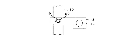
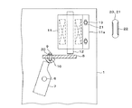
【解決手段】一方端に真空バルブが連結される回動自在のトリップキャッチ7と、トリップキャッチ7の他方端に係止される回動自在のトリップシャフト10と、トリップシャフト10に一方端が第1のボルト9で固定される回動自在のパドル8と、パドル8の他方端に可動軸12が当接するトリップコイル11と、トリップコイル11の固定部11aが第2のボルト13で固定される機構フレーム1とを備え、パドル8、固定部11aの少なくとも一方に、パドル8では第1のボルト9が貫通するレーストラック状の第1の貫通孔20を設け、固定部11aでは第2のボルト13が貫通するレーストラック状の第2の貫通孔21を設けたことを特徴とする。
【選択図】 図1
Description
最低動作電圧で開路動作をさせるため、パドル8やトリップコイル11の取付位置の微調整を行っている。これは、トリップコイル11では動作のバラツキ、各部品では寸法公差、組立では組立誤差などがあり、個々の操作機構で調整の必要が生じるためである。このため、閉路動作に影響を与えるパドル8やトリップコイル11などの部品の位置合せを容易に調整できるものが望まれていた。
2 主軸
3 主レバー
4、16 ローラ
5、17、18 可動ピン
6 固定ピン
7 トリップキャッチ
8 パドル
9、13 ボルト
10 トリップシャフト
11 トリップコイル
11a 固定部
12 可動軸
14 ワイプバネ
15 真空バルブ
19 開路バネ
20、21 貫通孔
22 弾性部材
Claims (4)
- 一方端に真空バルブが連結される回動自在のトリップキャッチと、
前記トリップキャッチの他方端に係止される回動自在のトリップシャフトと、
前記トリップシャフトに一方端が第1のボルトで固定される回動自在のパドルと、
前記パドルの他方端に可動軸が当接するトリップコイルと、
前記トリップコイルの固定部が第2のボルトで固定される機構フレームとを備え、
前記パドル、前記固定部の少なくとも一方に、
前記パドルでは前記第1のボルトが貫通するレーストラック状の第1の貫通孔を設け、
前記固定部では前記第2のボルトが貫通するレーストラック状の第2の貫通孔を設けたことを特徴とする遮断器の操作機構。 - 前記第1の貫通孔の長円を前記トリップコイルの軸方向と直交する方向に設け、
前記第2の貫通孔の長円を前記トリップコイルの軸方向と平行する方向に設けたことを特徴とする請求項1に記載の遮断器の操作機構。 - 前記第1の貫通孔、前記第2の貫通孔の長円の中央を、標準部品を用いて標準組立をしたときの最低動作電圧で動作する位置としたことを特徴とする請求項1または請求項2に記載の遮断器の操作機構。
- 前記第1の貫通孔、前記第2の貫通孔の長円の直線部に弾性部材を設けたことを特徴とする請求項1乃至請求項3のいずれか1項に記載の遮断器の操作機構。
Priority Applications (1)
| Application Number | Priority Date | Filing Date | Title |
|---|---|---|---|
| JP2010260536A JP5613027B2 (ja) | 2010-11-22 | 2010-11-22 | 遮断器の操作機構 |
Applications Claiming Priority (1)
| Application Number | Priority Date | Filing Date | Title |
|---|---|---|---|
| JP2010260536A JP5613027B2 (ja) | 2010-11-22 | 2010-11-22 | 遮断器の操作機構 |
Publications (2)
| Publication Number | Publication Date |
|---|---|
| JP2012113889A true JP2012113889A (ja) | 2012-06-14 |
| JP5613027B2 JP5613027B2 (ja) | 2014-10-22 |
Family
ID=46497887
Family Applications (1)
| Application Number | Title | Priority Date | Filing Date |
|---|---|---|---|
| JP2010260536A Expired - Fee Related JP5613027B2 (ja) | 2010-11-22 | 2010-11-22 | 遮断器の操作機構 |
Country Status (1)
| Country | Link |
|---|---|
| JP (1) | JP5613027B2 (ja) |
Cited By (1)
| Publication number | Priority date | Publication date | Assignee | Title |
|---|---|---|---|---|
| CN110718416A (zh) * | 2018-07-13 | 2020-01-21 | 上海电器股份有限公司人民电器厂 | 可调节分合闸线圈行程的装置以及采用该装置的断路器 |
Citations (6)
| Publication number | Priority date | Publication date | Assignee | Title |
|---|---|---|---|---|
| JPH02103705U (ja) * | 1989-01-26 | 1990-08-17 | ||
| JPH0628964U (ja) * | 1992-09-21 | 1994-04-15 | 日本高圧電気株式会社 | 開閉器の遠隔開閉操作装置 |
| US5504289A (en) * | 1994-03-30 | 1996-04-02 | Abb Power T&D Company Inc. | Circuit switching mechanism and charging system therefor |
| JPH09180593A (ja) * | 1995-12-26 | 1997-07-11 | Toshiba Corp | 遮断器用電動ばね操作機構 |
| JP2003123565A (ja) * | 2001-10-12 | 2003-04-25 | Kokusai Dengyo Co Ltd | 3ポジションスイッチ |
| US20120018287A1 (en) * | 2009-02-05 | 2012-01-26 | Siemens Aktiengesellschaft | Tripping Apparatus, Particularly For Circuit Breakers |
-
2010
- 2010-11-22 JP JP2010260536A patent/JP5613027B2/ja not_active Expired - Fee Related
Patent Citations (6)
| Publication number | Priority date | Publication date | Assignee | Title |
|---|---|---|---|---|
| JPH02103705U (ja) * | 1989-01-26 | 1990-08-17 | ||
| JPH0628964U (ja) * | 1992-09-21 | 1994-04-15 | 日本高圧電気株式会社 | 開閉器の遠隔開閉操作装置 |
| US5504289A (en) * | 1994-03-30 | 1996-04-02 | Abb Power T&D Company Inc. | Circuit switching mechanism and charging system therefor |
| JPH09180593A (ja) * | 1995-12-26 | 1997-07-11 | Toshiba Corp | 遮断器用電動ばね操作機構 |
| JP2003123565A (ja) * | 2001-10-12 | 2003-04-25 | Kokusai Dengyo Co Ltd | 3ポジションスイッチ |
| US20120018287A1 (en) * | 2009-02-05 | 2012-01-26 | Siemens Aktiengesellschaft | Tripping Apparatus, Particularly For Circuit Breakers |
Cited By (2)
| Publication number | Priority date | Publication date | Assignee | Title |
|---|---|---|---|---|
| CN110718416A (zh) * | 2018-07-13 | 2020-01-21 | 上海电器股份有限公司人民电器厂 | 可调节分合闸线圈行程的装置以及采用该装置的断路器 |
| CN110718416B (zh) * | 2018-07-13 | 2025-10-17 | 上海电器股份有限公司人民电器厂 | 可调节分合闸线圈行程的装置以及采用该装置的断路器 |
Also Published As
| Publication number | Publication date |
|---|---|
| JP5613027B2 (ja) | 2014-10-22 |
Similar Documents
| Publication | Publication Date | Title |
|---|---|---|
| EP1983542B1 (en) | Electrical switching apparatus, and latch assembly and latch engagement control mechanism therefor | |
| US9406470B2 (en) | Tri-stable flexure mechanism | |
| US6924720B2 (en) | Circuit breaker | |
| CA2629502A1 (en) | Electrical switching apparatus, and latch assembly and latch engagement control mechanism therefor | |
| US9208962B2 (en) | Circuit breaker including an anti-rebound system, anti-rebound system for a circuit breaker and method | |
| CA2852496C (en) | Electrical switching apparatus and trip latch assembly therefor | |
| EP4254462B1 (en) | Operating system of miniature circuit breaker and miniature circuit breaker having same | |
| JP5613027B2 (ja) | 遮断器の操作機構 | |
| KR102392161B1 (ko) | 회로 차단기용 개폐기구 | |
| JP4960072B2 (ja) | 回路遮断器 | |
| JP5475540B2 (ja) | 真空遮断器の操作機構 | |
| JP2014107184A (ja) | 遮断器の操作機構 | |
| JP6647303B2 (ja) | 電気スイッチング装置およびそのための極軸キャッチアセンブリ | |
| JP5714181B2 (ja) | 回路遮断器 | |
| JP4842045B2 (ja) | 引出形回路遮断器 | |
| JP5763957B2 (ja) | 真空遮断器 | |
| CN105810521B (zh) | 一种断路器故障脱扣执行单元 | |
| JP6508432B2 (ja) | 過電流検出装置及びこれを用いた遮断器 | |
| KR20160130917A (ko) | 회로차단기의 트립버튼 구조 | |
| CN108648936B (zh) | 一种低压开关动触头与操作机构的联接结构 | |
| JP4604584B2 (ja) | 開閉装置の操作機構及びそれを用いた開閉装置 | |
| CN106409622B (zh) | 断路器 | |
| US20050062564A1 (en) | Alarm output device for circuit breaker | |
| CN104364985B (zh) | 用于抽出式开关设备的抗震认证的永磁体moc锁件 | |
| JP2011238466A (ja) | 熱動形過負荷継電器 |
Legal Events
| Date | Code | Title | Description |
|---|---|---|---|
| A621 | Written request for application examination |
Free format text: JAPANESE INTERMEDIATE CODE: A621 Effective date: 20131025 |
|
| A977 | Report on retrieval |
Free format text: JAPANESE INTERMEDIATE CODE: A971007 Effective date: 20140515 |
|
| A131 | Notification of reasons for refusal |
Free format text: JAPANESE INTERMEDIATE CODE: A131 Effective date: 20140523 |
|
| A521 | Written amendment |
Free format text: JAPANESE INTERMEDIATE CODE: A523 Effective date: 20140722 |
|
| TRDD | Decision of grant or rejection written | ||
| A01 | Written decision to grant a patent or to grant a registration (utility model) |
Free format text: JAPANESE INTERMEDIATE CODE: A01 Effective date: 20140808 |
|
| A61 | First payment of annual fees (during grant procedure) |
Free format text: JAPANESE INTERMEDIATE CODE: A61 Effective date: 20140905 |
|
| LAPS | Cancellation because of no payment of annual fees |